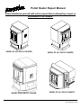
1
Pellet Heater Repair Manual
Please familiarize yourself with entire manual before attempting a repair or
adjustment of the heaters.
MODEL EF 3800 PELLET HEATER
MODEL EF3801PELLET HEATER
MODEL EF 5001 PELLET HEATER
MODEL EF 4001 PELLET INSERT
Sierra Products Inc., 5061 Brooks St., Montclair, CA 91763
P/N 140154 R1 01/10
Table of Contents
1. Introduction & Service Philosophy....................p. 3
2. Tools & Service Kit...........................................p. 4
3. Warranty & Return Parts Policy........................p. 5
4. Sample Claim Form..........................................p. 6
5. Service Calls.....................................................p. 7
6. Trouble Shooting Flow Charts..........................p. 8
7. Electric Schematic...................................p. 19 - 20
8. Component Replacement...............................p. 21
9. Illustrations.................................................p. 24 - 25
2
1. INTRODUCTION & SERVICE PHILOSOPHY
Following is a com prehensive service m anual which will assist both dealer or service personnel in m aintaining and servicing
the Easyfire Pellet Stoves.
Before getting into the specifics of service we would like to give an overview of our service philosophy and what we expect of
dealers when they take on the Easyfire line.
To becom e a pellet stove dealer m eans, by definition, that you will be m aking a com m itm ent to service. This is an appliance,
not another wood stove. If you are not prepared to enter into the appliance repair and service business then you should not
even consider becom ing a pellet stove dealer. Pellet stoves for the m ost part are wonderful heaters that will, with proper
m aintenance, provide years of clean, trouble free burning and quality heat. The sim ple fact is they have m any m oving parts,
unlike a wood stove, and these parts require lubrication and m aintenance. Because the pellet technology is new the user
m ust be educated and trained as to the proper use and m aintenance from season to season to avoid perform ance problem s.
For these reasons we require our dealers to set up a service departm ent that is dedicated to keeping the custom er happy with
a care free unit. The user m ust be m ade aware of his or her responsibilities and what is required to keep the unit working at
peak perform ance. The service departm ent and personnel should adhere to the following guidelines:
1. Service personnel should possess a high degree of m echanical aptitude, good com m on sense coupled with an
analytical m ind. The ability to read and use electrical schem atics, listen to custom er com plaints politely and determ ine what
m ight be causing the difficulty. The custom er needs to feel confident that the service person will be able to detect system
m alfunctions accurately, analyze problem s and solve them .
2. W hen entering the custom er's hom e the service person should be neat and clean in appearance, have the necessary
tools and parts required to attend to the problem and share with the custom er an explanation of charges and the custom er's
responsibilities in regards to future m aintenance. This m ust be done in such a m anner that there is no m isunderstanding or ill
feeling.
3. Rem em ber, it is the service person who represents your business when in the custom er's hom e. A good im pression by
the service person creates a good im pression of your business. The work is expected to be neat and professionally done.
4. W hen a custom er calls for service they should be greeted with a friendly calm ing voice, assuring them that the problem
will be given prom pt attention. It is im portant to get and give accurate, relevant inform ation. The following is an inform ation
guideline:
a. Custom er nam e, address and phone num ber.
b. Serial num ber of the stove.
c. W hat the custom er thinks is wrong.
d. W hen did the problem start.
e. W hen was the unit last serviced?
f. W hen and where was the stove purchased?
g. W ho installed the unit and when?
Note: At this point the problem can usually be dealt with by phone (90% of pellet stove problem s are lack of cleaning).
5. If you need to schedule a service call rem em ber the following:
Prioritize calls so that "no heat" calls are taken care of first. Do m inor calls next but don't put them off or you will only have an
angry, upset custom er who will cause a lot of grief for you and your business. Stick to your schedule. If you tell a custom er
you will be there tom orrow at 2:00 p.m . Be there at 2:00 p.m . or call well in advance to let them know, their tim e is valuable
too. If a part is needed and you don't have it, tell them , and order one as soon as you get back to the store. Give honest
responses, not creative excuses.
6. Once on the job the service person m ust use a system atic approach and think in term s of cause and effect. After som e
experience with the stove you should be able to look at the fire, flam e pattern, sounds and sm ells and detect problem s
im m ediately. To obtain this degree of expertise you m ust acquaint yourself with every com ponent and stove function. Never
guess!
3
TOOLS & SERVICE KIT
The tools and equipm ent needed for servicing the Easyfire Pellet Stove are as follows:
a.
b.
c.
d.
e.
f.
g.
h.
i.
j.
Good shop vacuum with blower capabilities.
Set of socket drivers which m ust include 11/32, 1/2 & 7/16 sockets or nut drivers.
Phillips and plastic coated slot screw drivers
Flashlight
Extension cord with ground
Allen wrench set (long handle)
W ire stripper and cutter
Electrical continuity tester with light or LED
Fully charged 12V Gel Cell Battery at least 30am p
Assorted crim p connectors with crim p tool
The Easyfire Service Kit which includes:
a.
b.
c.
d.
e.
Fan Motor, Feed Motor
Main Circuit Board
Switch Board (control board and knob)
One each T-1 and T-2 Sensor
Three (3) each fuses, (1A, SB) for rear panel AC Line
and 5m m fuse (6.3A, SB) for m ain board 12V line.
f. Digital read out volt m ulti m eter
h. One each bridge rectifier
4
EasyFire™ Pellet Heater
Warranty Replacement Program
EASYFIRE LIM ITED LIFE TIM E, THREE, ONE YEAR W ARRANTY
Sierra Products, Inc.(SPI) warrants to the original consumer that this stove will be free of defective materials and workmanship
for a period as listed below from the date of purchase. This warranty does not extend to any parts damaged through abuse,
accident, or neglect or warpage due to overfiring; nor does it apply if the stove has been repaired or modified without SPI’s written
authorization. If the stove proves to be defective in material or workmanship within the warranty period, SPI will, at no charge,
repair or replace (at its option) any defective parts, if the purchaser ships the parts or the stove, freight prepaid, to SPI or the
nearest authorized service center. SPI may require the consumer to supply reasonable proof of the stoves purchase date.
WARRANTY SCHEDULE:
OUTER BODY - LIMITED LIFETIME, FIREBOX COMPONENTS - THREE YEARS,
ELECTRIC COMPONENTS - ONE YEAR.
This warranty is in lieu of any other express warranty. Any implied warranties, including but not limited to any
implied warranty of merchantability or fitness for a particular purpose shall not extend beyond one year from the date
of purchase.
The purchaser's sale and exclusive remedy shall be for the repair or replacement of defective parts, as provided for in this
warranty. No other remedy (including but not limited to incidental or consequential damages for lost profits, lost sales, injury to
person or property, or other incidental or consequential loss) shall be available to the purchaser.
Some states do not allow limitations on how long an implied warranty lasts and some states do not allow the exclusion or limitation
of incidental or consequential damages, so the above limitations or exclusions may not apply to you.
SPI’s warranty obligation and the purchaser's rights under it can be altered only by a subsequent written agreement between SPI
and the purchaser.
The remedies provided in this warranty are void unless the attached warranty registration card is received by SPI within 30 days
from the date of purchase.
If you have a warranty claim or questions about the performance of your stove, you are requested to contact your dealer. This
warranty gives you specific legal rights, and you may also have other rights which vary from state to state.
W ARRANTY W ORK:
All warranty work m ust be authorized by the factory in advance of the repair and an authorization num ber assigned. A
warranty claim form m ust be com pleted and signed by both the repair person and the custom er. All claim s m ust be subm itted
to your distributor, if you are buying products through a distributor. In the event a unit has to be replaced, the warranty claim
form m ust be affixed to the unit with a description of the defect. Only the factory can authorize a heater return!
Any replacem ent parts required m ay be obtained from Sierra Products and will require a Purchase Order. Parts will be
invoiced to the dealer account and credit will be issue upon return to Sierra. All returned parts m ust be accom panied by a
warranty claim form . If you have a warranty claim for installing the part, use the sam e claim form and authorization num ber.
Please note... No credit will be issued until a warranty form with an authorization number is received along with the
defective part.
AUTHORIZED W ARRANTY PAYMENT:
Sierra Products will credit the distributor/dealer account the sum of sixty five dollars ($65.00) per occurrence and forty cents
($.40) per m ile, m axim um one hundred m iles round trip.
5
EasyFire™ Pellet Heater
Warranty Claim Form
Customer Information:
Unit Information:
Name:_________________________________
Address:_______________________________
City/State/Zip:___________________________
Phone:________________________________
Dealer Information:
RMA Number ____________
Model Number ___________
Serial Number _____________
Date of Purchase _________
Name:_______________________________
Date:__________________
Address:_____________________________
Mileage:________________
City/State/Zip:________________
Serviceman_________________
Describe Defect:
_____________________________________________________
_____________________________________________________
_____________________________________________________
_____________________________________________________
Describe Repair: _____________________________________________________
_____________________________________________________
_____________________________________________________
_____________________________________________________
Customer Verification:
I verify that the above repairs were made to my EasyFire Heater and that I am the original owner of the
above model.
Customer Signature:________________________________________
Service Person Verification:
I verify that the above repairs were made to the above EasyFire Heater.
Service Person Signature:_______________________________________
Distributor Authorization:_______________________________________
P/N 140154 10/07
Sierra Products Inc. 5061 Brooks St. Montclair, CA 91763
6
SERVICE CALLS
The objective when m aking a service call is to get the custom er up and running as quickly as possible. For this reason the
best m ethod of attack is to find the problem quickly and isolate the faulty com ponent and swap it out with the good com ponent
in your dealer service kit. The defective m odule or part can then be repaired to returned to the factory away from the
custom er's hom e.
W ith this objective in m ind the EasyFire troubleshooting can be divided into six (6) general categories:
1.
2.
3.
4.
5.
6.
The
The
The
The
The
The
fan and feed m otors.
m ain circuit board.
switch (control knob) circuit board.
tem perature sensors T-1 and T-2.
AC power line com ponents, i.e.,
wiring harness and connectors thereto.
These six (6) areas represent the areas where problem s m ight occur. They are listed in the order of highest probability,
based on their history and level of com plexity. The design of the electronics has been done with reliability as the highest
priority, and the com ponents which are under the m ost electrical or therm al stress are very conservatively rated.
The m ain board has been listed second due to the large num ber of parts, which increases its chances of failure on a
statistical basis. In practice, however, it should be the m ost reliable due to the rigorous test procedure each board goes
through before being installed on the stoves. Because of this m echanical item s such as the m otors should be suspect first.
Rem em ber, ninety per cent (90%) of pellet stove failures are due to im proper m aintenance by the end user! Check the stove
for cleanliness and routine m aintenance before doing any m echanical service work.
Following is a list of com plaints and/or service problem s which represent at least ninety five (95% per cent of possible service
calls:
1.
2.
3.
4.
5.
Stove not running at all.
Feed m otor runs, but no fan.
Fan m otor runs, but no feed.
Stove runs, but shuts down about 10 m inutes after start up.
Stove runs, but keeps shutting down with over-tem p (red)
LED com ing on.
6. Stove runs, but heat output rem ains at the LOW level, even
when switch is on HIGH.
7. Stove does not run on battery or battery does not charge.
8. Stove runs on FAN position but when switched to LOW , MEDIUM
or HIGH shuts off im m ediately.
9. Stove seem s to be running very HIGH or CLEAN m ode at all
tim es.
10. Fan speed seem s norm al for each position, but feed rate
seem s excessive even on LOW .
Following is a trouble shooting Flow Chart for each of the problem s outlined above. If you follow the flow chart carefully each
of the problem s can be solved quickly and easily.
7
Trouble Shooting Flow Chart #1 - Stove not running at all.
8
Trouble Shooting Flow Chart #2 - Feed motor runs, but no fan.
Trouble Shooting Flow Chart #3 - Fan motor runs, but no feed.
9
Trouble Shooting Flow Chart #4 - Stove runs, but shuts down in 10 minutes (Make sure stove is hot
enough - 140°F).
Trouble Shooting Flow Chart #5 - Stove runs, but shuts
down random ly with over-tem p LED On.
Steady Red = High Tem p
Blinking Red = Blocked Flue
10
Trouble Shooting Flow Chart #6 - Stove runs, heat output stays Low, even on High setting.
Trouble Shooting Flow Chart #7 - Stove will not run on battery or charge battery.
11
Trouble Shooting Flow Chart #8 - Stove runs in fan only m ode, but when turned to Low , Med, or High, it shuts off
immediately.
Trouble Shooting Flow C hart #9 - Fan always very high, all
modes except off.
Trouble Shooting Flow Chart #10 - Feed always very high, all
modes except off.
12
Check the feed “trim ” button and adjust to higher
(clockwise) setting. If the feed is too low, the stove
will cool down and when it reaches a lower
tem perature will shut down autom atically. This can
be corrected by adjusting the feed setting to a
higher setting.
Trouble Shooting Flow C hart #11 - Stove runs fine and then
shuts off for no apparent reason.
Trouble Shooting Flow Chart #12 - Fan speed erratic
(Surges)
Feed System exploded view
13
Pre 2005 control sw itch assembly
2005 and new er control sw itch assembly
14
EasyFire B Model Pellet Heater Quick Troubleshoot and Technical Guide
SPI’s EasyFire pellet heaters are designed to operate as a seasonal zone heater burning 1/4" wood pellet fuel. Utilizing a
12VDC control and drive system allows for extended battery operation when AC power fails. The following outlines the
general operating param eters and trouble shooting encountered during installation and seasonal operation. Basic
operation is controlled com bustion of wood pellets m etered by the feed drive system into a burn pot and a
com bustion/convection fan m otor providing separate air for com bustion and heat exchange. This process is controlled by a
digital m ain controller which m onitors all function through two sensors and incom ing outgoing operating voltages.
Additionally, starting functions are provided by an industrial style cartridge heater located in the burn pot and both internal
and optional therm ostat.
Standard operation: W ith both 120VAC and 12VDC battery power attached and a functional pellet flue system the heater
is designed to operate continuously during the heating season. On a daily bases the heater requires fuel to be added to the
storage hopper and depending on the fuel quality, burn pot area cleaned. Starting and operating sequences are controlled
by an operating software program contained on a EPROM m em ory chip. Fuel rate is controlled by m ode setting and trim
position (standard trim knob setting is 9:00 and is located on control panel next to operation buttons). Norm al start up and
operation sum m ary follows:
Condition - Heater is cold, power connected, button to “OFF” position. Hopper door closed (safety switch closed). External
therm ostat jum ped (factory standard) or optional therm ostat closed to call for heat.
1)
Select a run button (Low, Medium , High) and press. The LED light will shift from OFF to run button.
A)
Feed m otor starts initial fuel shot (approx. 40 seconds) and ignitor ON. Ignitor will begin to start heating
and pass 300 degrees in 30 seconds.
B)
Fan m otor starts in 60 seconds @ 3 volts providing com bustion and convection air. Feed will cycle OFF
com pleting the start up fuel shot. Sm oke will be visible norm ally visible through the door glass with in 2
m inutes.
C)
Feed will cycle ON for short periods during the start cycle add sm all am ounts of fuel. Heater continue in
START UP m ode until tem perature rise is confirm ed by sensors or for a total of 10 m inutes.
If tem perature does not increase by 15C during this STARTUP phase the heater will begin the SHUTDOW N (for
further inform ation read SHUTDOW N in several paragraphs).
2)
RUN m ode begins when tem perature rise is achieved (norm ally within 5-7 m inutes).
A)
Fan increases based on run button selected. Feed pulses increase based on tem perature and TRIM
setting. Feed trim adjustm ent allows for a lower or higher average fuel delivery.
Initial flam e is high based on a cool heater and fuel shots provided for start up. As operating tem perature is
reached the feed pulse will decrease and flam e will drop.
B)
Feed rate will vary up and down as the heater adjusts for operating tem perature. Tem perature m easured
at T-2 sensor m ounted on fan housing m anifold.
C)
Heater will continue to operate as long as fuel, therm ostat setting, and operating button rem ains.
Condition - Shutting down operating heater. Selecting the OFF button or external therm ostat no longer calls for heat.
A)
B)
Feed m otor im m ediately stops. No fuel is added to the burn pot and the coals rem aining began the burn
out.
Fan is reduced to shut off voltage of 5 volts and m aintained until sensor T-2 records a 20C reduction of
tem perature or 20 m inutes tim e elapses.
Other related operating parameters
Three basic functions are constantly m onitored during operation including flue drafting, operating tem peratures, and AC
power input. Blocked flue will cause an unsafe condition and will cause the unit to shut down with a steady RED fault
indication noted on the control panel. Continued high tem perature m ay cause a unsafe condition. The heater will stop the
feed during high tem peratures to allow the heater to cool. A flashing RED will indicate high operating tem perature. AC
power outage will stop external therm ostat function if the optional battery is connected allowing the heater to run
continuously while AC is out.
Com mon operating problems:
(Refer to installation m anual and repair m anual for additional inform ation regarding specific com ponent replacem ent and
testing).
15
Basic tools required for troubleshooting - Multi Volt/Ohm Meter, standard and phillips screw drivers, standard jewelers
screw driver (fan speed adjustm ents on m ain control board).
No power - Power is provided by both AC and DC supplies. There are two replaceable fuses located near the power
connections. They are identified as Main (1 am p) and Ignitor (5 am p). If AC power is present to the m ain control system a
LED will be lit on the OFF button. If DC power is present a GREEN LED will be lit on the control panel.
Quick Testing 1)
Check AC power with volt m eter at wall socket - 115VAC.
2)
Check DC power at battery - 12VDC.
3)
Rem ove fuses and check continuity with OHM m eter. Blown fuses can be cause by voltage spikes (lightning,
power com pany). If fuse is found blown, replace only once and retest. If the fuse blows again further
troubleshooting is required before further fuse replacem ent.
Start up:
No fuel - Fuel located in the hopper is feed by a auger from the hopper bottom up to the shoot which directs the pellets into
the burn pot. The feed m otor is controlled by the m ain control system and on m odels EF3801B, 5001B, and 5001U-B a
hopper safety switch (EF4001-B auger can not be accessed from the hopper door). The switch will disable the feed system
if the hopper lid is open. The switch is located on the upper right hopper vertical panel and is accessed through a sm all
panel. Fuels is only feed in Low to High operating m odes and requires “prim ing” auger. If hopper is out of fuel, cycle from
OFF to LOW several tim es to allow pellets to feed into burn pot.
Quick Testing 1) Confirm hopper lid is sitting on the switch arm and the arm is closing. W ith hopper lid open, push the switch arm down
and listen for click noting switch closure. W ith heater cold, and lid open, push switch arm down, push Low and the feed
m otor should start to turn.
2) Confirm feed m otor is not jam m ed by em ptying hopper and verifying a foreign object has not be caught. Rem ove top
cover from feed tube from inside hopper if there is any question. If the feed m otor is m echanically jam m ed, the control
system has a built in circuit breaker. The breaker will require a reset by cycling from OFF to LOW . Do not recycle m ore
than three tim es so the circuit does not becom e dam aged by overheating.
3) Pellets Jam m ed in feed shoot (above burn pot). Rem ove all jam m ed pellets and clean shoot with scraper.
Ignitor does not heat up - The ignitor has a separate 120VAC circuit which includes a fuse, relay, and ignitor. This circuit is
activated by the m ain control board via a 12VDC wire harness lead. W hen the m ain control call for start the 12VDC circuit
is closed sending 12VDC to the relay. As the relay closes, the 120VAC circuit is com pleted and the ignitor begins to heat.
As noted in prior section, if 120VAC power is not available the heater will still start the fan and feed if 12VDC is connected
allowing a m anual start with starter and m atch light.
Quick Testing 1)
2)
3)
Inoperative ignitor m ost likely have a blown fuse. Rem ove the 5 am p ignitor fuse and test with OHM m eter.
Replace if blown. As noted before if fuse blows again then further testing is required.
Testing ignitor requires access to the relay located near the m ain board assem bly. Access is through the lower
right pedestal for the 3801/5001, junction box on the 4001 insert, and lower right cabinet for the 5001U. Rem ove
the power to the unit. Unplug the ignitor lead from the relay and the neutral circuit. Using the OHM m eter check for
continuity between the two leads. If the circuit is open the ignitor has failed. If the circuit is com plete check one
lead and then ground the other lead to the ignitor base. If circuit is com plete ignitor has failed. A grounded circuit
will cause the fuse to blow.
If ignitor check out, rem ove the harness leads to the relay and using the volt m eter set to 20VDC, confirm 12VDC
when the power is reapplied a run button is pushed. If 12VDC is found then the relay has failed.
Heater starts then burns out - The start up is controlled by the control system and best results are from a cold start. If a
warm heater is im m ediately restarted it m ay not be able to confirm the required tem perature increase as the heater
tem perature is already warm and the tem perature is actually falling during the initial start up. Allow the heater to cool and
shut down before restarting.
Trim settings - W ill not change the first portion of the start up however will effect the initial run m ode. If the trim is fully
counter clockwise (Lowest) the heater m ay run low on fuel, m ost likely if the operating conditions are warm . High or Max
16
trim settings m ay cause the opposite problem as the heater feeds to m uch fuel and allows the HIGH TEMP control stop
the feed to cool the stove. Best starting trim setting is the m id point or 9:00 o-clock.
High tem p starts will also occur if the burn pot has additional fuel prior to start up. This additional fuel which is then added
too as the start cycle begins pushes the tem peratures up as the heater starts. This is considered an tem perature
overshoot as the tem perature clim bs quickly.
Heater will not start when run button is pushed - Check external therm ostat jum per or rem ote therm ostat as the unit will
not attem pt a start unless this circuit is closed.
Run mode Troubleshooting:
Once the heater reaches the run m ode it will continue operation by using the coals in the burn pot to light the pellets
continuing to fall. If the coal bed burns down at som e point the pellets m ay not light and then the heater will shut down.
This is norm ally confirm ed by finding the burn pot with unburned fuel and shut off. This can also happen if the hopper runs
low on fuel or the fuel bridges (hangs on the hopper sides).
Run m ode problem generally are either operational or lim its exceeded - Blocked Flue (loss of flue draft) or High
Tem perature is exceeded. Blocked flue indication is a solid RED LED on the control panel and requires a recycle of the
heater to clear. This is for the operators protection as a blocked flue could cause a dangerous condition. Block flue m ost
likely is not fully blocked and will occur if the flue pipe is subject to high wind conditions or is blocked by ash. If this
happens during initial installation a corrective action to the flue system will be required. Check the installation m anual for
flue recom m endations.
Operational problem s are generally related to ash build up in the burn pot or the heat exchange system and can be correct
by cleaning.
Over Feeding - Over feeding is a com m on problem and is related to a lack of com bustion air rather than to m uch fuel. If
the heater is clean and seem s to feed m ore fuel adjust the trim down to slow the feed rate. If the heater has been operated
for som etim e since the last cleaning then shutting it down and cleaning will solve the over feed. Check the door for proper
adjustm ent as a partially closed door will cause reduced com bustion air. Operating the heater for an extended tim e with an
open door will cause a shut down with RED LED and require a restart.
Im m ediate RED LED when a run m ode is selected indicates a failed sensor (generally a T-1). Replacem ent of sensors are
accom plished by rem oving the rear access panel and norm ally requires rem oving the flue pipe. Review repair m anual for
additional inform ation.
Shutdown:
Shut down is the sim plest m ode as the feed is stopped and the fan continues to operate until the heater is cool. If the fan
continues to run after it is fully cold then the T-2 sensor and the m ain control did not register the required tem perature
reduction. Unplug the heater to reset and run again. If problem persists then the T-2 sensor or the control system will
require com ponent replacem ent.
Battery Operation Troubleshooting Battery operation requires a fully charge 12VDC battery capable of sustained 2 am p/hr. loads while m aintaining a m inim um
of 11.2 VDC. This voltage is required for proper system operation. Most battery operation problem s can be traced to a
battery in pour condition.
Quick Testing
Rem ove battery from heater and charge overnight with autom otive type battery charger. Test battery with autom otive load
tester. Replace if required. Testing connections from term inals on rear of heater back to the harness. If all connects are
secure a m ain control board will be required.
Additional detailed inform ation is contained in the installation and repair m anuals. Please refer to these for in depth
troubleshooting guides and harness replacem ent.
17
Component Adjustm ents and Replacem ent:
Main Control Board - Main control board is located in the lower right pedestal (3801/5001) or lower right rear - 4001 insert
and right switch plate for the 5001U. The control board is held in place with several phillips screws.
Fan speed adjustm ents are accom plished by turning the LOW and HIGH fan pots on the lower right corner. These
adjustm ents are m ade in the corresponding run m ode. Factory settings are based on fan voltage as read across the m otor
term inals 6.8VDC LOW , and 9.0VDC HIGH.
A GREEN LED light flashes on the control board to confirm AC or DC power is present.
Switch Board - Switch board is attached to access panel with several phillips screws. Harness plugs into bottom of switch.
Sensors - Access for sensors is through the rear panels. Both the T-1 and T-2 sensors are the sam e sensor type m ounted
differently. T-1 is m ounted on the exhaust side of the com bustion fan housing. It is held in place with a tie wrap. T-1 sensor
allows for cabinet air to drawn through the high tem p plastic holder. W hen door is open or flue blocks the flow reverses. T2 sensor is attach to a alum inum block and attached to the m anifold. W ire harness connections should be secure and not
pulled tight.
Additional inform ation is available on line@ www.sierraproductsinc.net/pages/custom er_service
Technical Custom er Service - 909-399-3355x29
Red Light Fault Indications:
W hen the Hi-Tem p/Flue indicator light com es on (red lite beneath control knob) it m eans a fault has been detected in
either the flue system , over tem perature, or fan/feed m otor.
Slow Flash Red Light - Indicates a blocked flue. Check flue and clean out for built up ash deposits.
Solid Red Light - Indicates an over tem perature. Check the air intake at rear of unit. Turn the feed trim down 25% to
reduce fuel rate.
Fast Flash Red Light - Requires unit to be unplugged to reset. Indicates a feed m otor jam or fan m otor fault. Fan m otor
test would require running unit on “fan and clean” only to determ ine if red light indication is repeated. If not, feed system is
jam m ed and requires the hopper access cover to be rem oved and jam m ed m aterial to be rem oved
18
19
20
EF AutoLite Igniter
Replacement Instruction
Please read this entire instruction before attempting repair.
WARNING - ELECTRIC SHOCK POTENTIAL.
All repairs must be accomplished with the
115VAC and 12 DC power disconnected from
heater.
Basic start up operation is as follows (with therm ostat
jum ped):
1)
2)
3)
4)
From “Off” press operating button (Low). DC controller
energizes the 115VAC relay com pleting the igniter high
voltage connection. Igniter tem perature im m ediately
rises from room tem perature.
Com bustion fan starts at 1 m inute along with feed m otor
for 1 ½ m inutes providing start up fuel.
Pellets start to ignite approx. 3 to 4 m inutes. Feed m otor
starts at 4 m inutes to provide additional start up fuel.
At 7 m inutes unit should have flam e in burn pot. If no
tem perature rise is noted by T-1 (sensor) at 20 m inutes
heater starts shut down process.
TROUBLESHOOTING IGNITER SYSTEM
Figure 1 Insert Connection Panel
The igniter system incorporates a cartridge style high
wattage 115VAC igniter located at the bottom of the pellet
burn pot. This system is continuously cooled by incom ing
com bustion air and provides years of general service.
However, for the igniter to work properly the burner pot m ust
be cleaned as required to allow the pellets to fall onto the
igniter. Generally, this is accom plished during norm al
cleaning which would include rem oving the burn pot and
brushing the ash from the pot and igniter. Rem oving the
screen from below the ignitor and brushing all ash from the
burn pot holder will also aid in the starting process.
Check the igniter rod surface for disintegration or obvious
dam age. If any white ceram ic m aterial is showing through
the SS protective cover the igniter should be replaced.
Figure 2 Stove Connection Panel
Once the burn pot is cleaned and the igniter inspected the
rem aining system checks are electrical. A sim ple check of
the system m ay be accom plished on a cold heater by
placing a gloved hand on the igniter rod and pressing one of
the operating button (Low). The igniter will start to get hot
im m ediately (2 minute tem perature 500°F). If not
tem perature rise is noted then continue with electrical
trouble shooting.
GENERAL INFORMATION
Your EASYFIRE Pellet Heater is equipped with the Autolite
Autom atic ignition and operating system .
The AutoLite system is integrated into the heater to allow for
autom atic start up using a heating elem ent located in the
burn pot. This elem ent starts the initial fire required to burn
the wood pellets. The system operates on 115VAC power
supplied through a separate fuse for seven m inutes during
the initial heater start up. After the seven m inute period the
AutoLite system is deactivated and the heater operates
based on the EasyFire digital control system requirem ents.
If the house AC power should quit, the AutoLite system will
not be available. however, with the optional battery attached
the heater can be m anually lit.
Autolite W iring Diagram
21
ELECTRICAL TROUBLE SHOOTING
W ARNING: Only a trained technician should attem pt to
repair a pellet heater electrical system .
Note: All tests should be accomplished with the unit
thermostat by-passed.
Rem ove both AC and DC power from unit. The igniter
system is protected with a 5 am p fuse located on the back or
side of the heater (Figure 1). The igniter is switched “Off”
and “On” by the control system via a relay located in the
lower right pedestal in front of the control board
(EF3801/5001) or in lower left rear of the unit accessed from
the back (EF4001). W iring on all igniter system s are the
sam e. The following test steps will require a m ulti-m eter with
AC/DC volt and ohm functions:
a. Unplug heater from wall outlet and 12VDC power!
b. Rem ove 5 am p fuse holder cap and fuse by pressing
in and turning counter clockwise. Test fuse with ohm
m eter to confirm is not “open”. If fuse is open go to
Testing Igniter “d”. If fuse is good continue.
c. Check 115VAC power wire connection to relay and
neutral wire connection to igniter term inal. This can be
accom plished with the ohm m eter. If wire is
disconnected or open replace.
d. Disconnect igniter leads from relay and neutral. Test
continuity with ohm m eter between leads. If open
igniter is defective. If continuity exists then check for
internal grounding by checking each lead to the
shielded conduit of the igniter leads. If continuity exists
to ground then igniter is defective. If m eter reads open
on both leads to ground then igniter should produce
heat when properly connected to 115VAC.
e. W ith igniter disconnected from relay, attach volt m eter
(set m eter to 200VAC) leads to relay 115VAC out
term inal and igniter neutral. Reapply 115VAC power.
Press operating button low. Relay should im m ediately
engage applying 115VAC to m eter. If m eter has
115VAC then replace igniter as it should be activated.
If no AC power outputted from relay. Continue to next
test.
f.
Disconnect DC control wires from harness to relay.
Attach volt m eter (set m eter to 20VDC) leads to
harness term inals. Reapply 115VAC power. Press
operating button low. Control system should
im m ediately engage applying 12VDC to m eter. If
m eter has 12VDC then replace relay as it should be
activated. If relay does not engage, exchange control
board and/or m ain switch board.
REPLACEMENT PARTS:
ITEM
NO.
PART
NO.
DESCRIPTION
1
120120
12VDC RELAY
2
120117
CARTRIDGE HEATER
3
120118
AUTOLITE CONTROL SW ITCH
4a
202163
BURN POT SCREEN 5001
4b
202164
BURN POT SCREEN 3801/4001
5a
300501
BURN POT 5001-AUTOLITE
5b
300500
BURN POT 3801/4001-AUTOLITE
6
110510
5 AMP FUSE MDL5 (NOT SHOW N)
Customer Service & Replacem ent Parts
Replacement parts are available from your local dealer or
on-line @ www.sierraproductsinc.net . or call or write:
Customer Service
Sierra Products, Inc.
5061 Brooks St. Ste. B,
Montclair, CA 91763
Phone 1-909-399-3355
Fax 1-909-399-3357
www.sierraproductsinc.net
Sierra Products, Inc. 5061 Brooks St. Ste. B, Montclair, CA 91763
22
P/N 140804 10/07
Sierra Products, Inc. 5061 Brooks St. Ste. B, Montclair, CA 91763
23
P/N 140804 10/07
Pre 2004 Pellet Stove Wiring Detail
Sierra Products, Inc. 5061 Brooks St. Ste. B, Montclair, CA 91763
24
P/N 140804 10/07
2005 HARNESS WIRING DETAIL
Sierra Products, Inc. 5061 Brooks St. Ste. B, Montclair, CA 91763
25
P/N 140804 10/07
EF3801/4001 V1 Feed System
Service or Repair Instruction
Figure 1
OVERVIEW
The EasyFire feed system consists of four m ain com ponents, feed
m otor and m ounting plate, feed auger shaft, feed disk, and feed disk
bushing (Figure 1). These com ponents are designed to provide
thousands of hours of service and rarely require service or
replacem ent. Operation of feed system is controlled by the m ain
control board based on the stoves tem perature and heat setting. Unlike
other pellet stoves, the system operates by increasing and decreasing
the speed of the auger and disk. Pellets are pushed forward toward the
disk and as the disk rotates clockwise (from front of stove) allows the
pellets to be feed into the shoot. Three feed disk sizes are available
with the standard = 1, m edium = 2, and large = 3. #3 feed disks are for
large or long pellets only. If overfeeding or under-feeding is a problem
and adjusting the feed trim will not com pensate, changing the feed disk
is advised.
Rem oving and Replacing the Feed Assem bly: The feed assem bly
and gear m otor is accessed by rem oving the rear inspection panel for
both the heater and insert. Rem ove the four or six #8 screws
attaching the inspection cover and rem ove cover. Rem ove all pellets
from hopper and feed disk area inside unit. Locate feed m otor and
unplug wire harness connections (note location of red banded wire on
m otor to assure proper rotation of m otor). Rem ove wing nuts (or #10
nuts on som e units) attaching feed m otor bracket to rear of feed shoot.
Gently rem ove feed assem bly by pulling toward the rear of unit. The
feed shaft m aybe rem oved by loosening the allen screws holding the
shaft coupler. Rem ove the two #8 phillips screws holding the feed
m otor bracket to the gear m otor. Reverse process to install feed
m otor assem bly.
Bushing replacem ent: Disk bushing m ay be replaced by rem oving 2#8 retaining screws and carefully prying with a large flat blade screw
driver from inside hopper (Figure 2). To re-install bushing clean area
with thinner or alcohol and apply a sm all am ount of red lock-tight to bushing. Align with plate and carefully pry back with
screw driver. Straighten bushing and install retaining screws.
Shaft or Disk Replacem ent: The feed disk and shaft depth are set
at the factory to allow the feed disk to ride fully in the feed disk
bushing. W hen replacing either com ponent, m ake sure the installed
disk ride toward the rear of the disk (Figure 3) and does not extend
to far forward. If the disk is set to far forward it m ay jam b causing
the shaft to bend or break. Assem ble the new com ponents onto the
m otor drive loosely then install into stove. Carefully position disk and
m ark or tighten disk onto shaft. Rem ove disk and m otor assem bly
from stove and tighten with 1/8" allen wrench.
NOTE: W HEN ASSEMBLING THE SHAFT AND COUPLER,
ALW AYS USE A SMALL AMOUNT OF LOCK TIGHT (RED) ON
ALLEN SET SCREW S. AFTER THE ASSEMBLY HAS BEEN
INSTALLED THE FEED DISK MUST RIDE IN THE CENTER OF
THE FEED BUSHING.
Figure 3
5061 Brooks St. Montclair, CA 91763
800-527-4790 Fax 1-909-399-3357
www.sierraproductsinc.com
P/N EF3801 4001 Sensor replacment 4/04
26
EF3801/4001 T-1/T-2 Sensor
Replacement Instruction
OVERVIEW
First production 2005 stoves Serial #3384 to #3420 require precautionary replacem ent of both T-1 and T-2 sensors. The
sensors located in the stove body sense the operating tem peratures and overall param eters of the stove. The T-1 sensor
provides blocked flue and operating sensing while the T-2 sensor provides start up, shut down, and over tem p. sensing.
The first 26 units have a sensor assem bly attached in such a way that m ay cause the stove to act erratically. As a
precaution we are requiring replacem ent of the sensors and offering a repair credit. Please contact custom er service @
800-527-4790x29 for further inform ation.
T-1 and T-2 Sensor Replacem ent:
Removal from 3801 and 4001 Insert: The T-1 and T-2 sensors m aybe accessed by rem oving the inspection covers on
back of the unit. The T-1 sensor is installed into to the right side of the com bustion housing just above the exhaust tube.
Unplug the harness connector to the sensor. Using a wrench, unscrew the brass fitting and sensor holder from the
exhaust pipe. The T-2 sensor is located right of the com bustion housing attached on the lower portion of the m anifold.
Unplug the harness connector the sensor. Rem ove the #10 nut attaching the sensor holder and rem ove the sensor.
Reverse process to install new sensor fitting and holder. Reinstall the rear panel and confirm standard operation.
5061 Brooks St. Montclair, CA 91763
909-399-3355 Fax 1-909-399-3357
www.sierraproductsinc.com
27
REMOVAL AND REPLACEMENT OF COMPONENTS
W ARNING: RISK OF ELECTRIC SHOCK! REM OVE ALL POW ER CORDS FROM UNIT BEFORE ATTEM PTING ANY
SERVICE.
1.
Circuit Board: The circuit board is located on the lower right hand side of the heater or insert (facing
from the front fig.1 - pg. 21).
Rem oval from Heater: Rem ove the two #8 phillips screws securing the panel to the pedestal side. Open the panel
by lifting up and out. Lay panel flat and rem ove two #8 phillips screws securing the control board stand-offs to the panel.
Gently rem ove board from 44 pin connector by firm ly holding panel and pulling board toward you. Rem ove #8 nuts
attaching stands to the board and rem ove stands (these nuts are located on the lower right and left corners of the board).
Reverse the process to install new control board.
Rem oval from Insert: Rem ove the two #8 phillips screws securing the control cover from the hopper side.
Rem ove the two #8 phillips screws attaching the control board the stand-offs (these screws are located at the lower right
and left corners of the board). Gently rem ove board from 44 pin connector by pulling down on the board. Reverse the
process to install a new control board.
2. Fan M otor: The fan m otor is located directly under the com bustion fan housing. Access is provided through
the rear inspection covers on both the heater and insert. Rem ove the #8 screws attaching the covers. Rem ove the wire
harness leads to the m otor noting there position both red and black. Next rem ove the plastic convection fan blade by
carefully pushing against the fan hub. Rem ove the four #10 nuts holding the fan m otor base plate to the housing. Carefully
pry the base plate breaking the factory silicon seal. Rem ove m otor from unit. Using a long allen wrench loosen the allen
set screws holding the com bustion fan blades on the m otor shaft. Rem ove the two #10 nuts holding the m otor m ount tho
the fan plate. Rem ove the two #8 phillips screws holding the m otor m ount to the m otor. Reverse the process to replace fan
m otor assem bly.
NOTE: WHEN INSTALLING THE COM BUSTION FAN BLADES ON THE M OTOR SHAFT, USE LOCK TIGHT (RED)
ON THE ALLEN SET SCREW S. THE PROPER POSITION OF THE BLADES IS THE OUTER BLADE POSITIONED AT
THE END OF THE SHAFT AND THE SECOND BLADE TIGHT TO THE BACK OF THE FIRST. W HEN ASSEM BLING
THE FAN M OTOR PLATE BACK INTO THE UNIT, USE HIGH TEM PERATURE SILICONE SEAL ON CLEANED
M ATING SURFACES.
Fan m otor brushes m aybe replaced by carefully rem oving the plastic screw caps on each side of the m otor and replacing
with factory replacem ents.
3. Control Sw itch: The control switch is located on the right side of both the heater and insert. In both units
rem ove the two #8 phillips screws holding the cover. Using a sm all blade standard screw driver carefully loosen the set
screw on the control knob. Next rem ove the 9/16 nut attached to the switch shaft. Rem ove the switch and unplug the
harness connector. Reverse procedure to install new
switch.
4. Transformer and Rectifier: The transform er and rectifier are located inside the cabinet on both the heater and
insert. Rem ove the inspection cover on the rear and locate the transform er. Rem ove the two #6 phillips screws and nuts.
Rem ove the wires noting the positions. Rem ove the transform er. The rectifier m aybe rem oved by unplugging the wires
from the harness and transform er (note the position of the red and black harness wires). Rem ove the #6 phillips screw
and nut. Rem ove the rectifier. Reverse the procedure to install new parts.
5061 Brooks St. Montclair, CA 91763
909-399-3355 Fax 1-909-399-3357
www.sierraproductsinc.com
28
5061 Brooks St. Montclair, CA 91763
909-399-3355 Fax 1-909-399-3357
www.sierraproductsinc.com
29
5061 Brooks St. Montclair, CA 91763
909-399-3355 Fax 1-909-399-3357
www.sierraproductsinc.com
30
B Model General
Service Instruction
OVERVIEW
W ith one season of field service experience three service item s have
been noteworthy and should be com pleted during the next unit service.
Feed System Gasket and Attachment Nuts: Feed system
attachm ent in past EF units had been accom plished with wing nuts.
W e have noted that the nuts tightened by hand m ay not be sufficient to
properly secure the feed drive. If the drive becom e loose the feed
gasket m ay fail and allow saw dust to fall into the cabinet. To correct
this we have available 10-24 washer locking nuts to replace the wing
nuts. Replacem ent of the feed gasket should include gluing the gasket
to the bottom of the feed hopper using silicone sealant.
1)
Rem ove the units rear panels to gain access to the feed drive.
Em pty the hopper of fuel. Loosen and rem ove the wing nuts.
Lower the feed drive from the hopper (Figure 1). Rem ove old
gasket.
2)
Apply autom otive type silicone gasket m aterial around feed drive
hole (Figure 2).
3)
Press silcone applied gasket side to bottom of hopper (Figure 3).
Figure 1
4)
Carefully install feed drive so as to not dam age gasket. Install new
lock nuts and tighten with 3/8 wrench (Figure 4).
Note: silicone gasket material should squeeze out from edges both
inside hopper and out. Remove excess silicone.
*** Prior to re-installing back panels complete the following services ***
Figure 2
Figure 3
Sensor and Sw itch Harness Connections: These digital
com ponents connect to the m ain circuit board through the m ain wiring
harness. The
connections
utilize industry
standard pin and
sockets.
Operating at low
DC voltage these
connections are
subject to
vibration, dust,
and m oisture. To
m inim ize the loss
of contact these
three connections
should be coated
with a sm all
am ount of
Figure 4
5061 Brooks St. Ste B Montclair, CA 91763
800-527-4790 Fax 1-909-399-3357
www.sierraproductsinc.net
P/N B Model General Service 09 01/09
31
“Silicone Di-Electric Com pound”. This non-hardening
silicone will keep m oisture and dust from effecting the
connection along with m inim izing vibration. Available at
auto parts and electronic stores a sm all tube will service
m any units.
1)
Carefully pull the harness connection end connector
from each of the two sensors and switch board
(Figure 5).
2)
Apply a sm all am ount of di-electric lube to the
bottom of the connector allowing the lube to push
into each pin opening.
3)
Apply a sm all am ount to pin area on receiver and
plug harness back into original connection.
Checking Harness for Proper Slack: During unit
assem bly the harness is routed through the cabinet and
bundled to keep wiring away from hot surfaces. The
bundles m ay cause the harness connections to be pulled
during servicing and allow for a poor connection. Check
the harness and confirm there is at least ½" play when
m oving the bundle or harness up (Figure 6).
Figure 5
1)
Check all harness connections to m ake certain there
is adequate slack. If additional slack is needed
carefully pull additional wire from bundles.
Cleaning Cabinet and Re-assem bly: Vacuum or sweep
saw dust from cabinet prior to assem bly of the rear
access panels. Dust in the heat exchange area can
cause sm ells during operation.
NOTE: CHECK FAN BLADE AFTER ASSEMBLING
REAR PANEL TO CONFIRM NO INTERFERENCE
FROM FAN SHROUD.
Upon com pletion carefully reinstall upper rear panel and
confirm the fan blade is not hitting the fan shroud prior to
powering up unit (Figure 8).
Figure 6
After com pleting the installation of the rear panel and tightening all the
phillips screws. Plug the heater back into AC power and test run by
running fan m otor on “Fan” setting for 2 m inutes and then running on
“Clean” for 30 seconds. Run unit through a beginning start up by
pressing “Low” and allowing fan and ignitor to start up. If all appears to
activate reinstall unit.
Additional information is available on line@
www.sierraproductsinc.net/pages/custom er_service
Technical Custom er Service - 909-399-3355x14
Figure 7
5061 Brooks St. Ste B Montclair, CA 91763
800-527-4790 Fax 1-909-399-3357
www.sierraproductsinc.net
P/N B Model General Service 09 01/09
32
B Model Fan Motor Brush
Service Instruction
OVERVIEW
The EasyFire heater is equipped with a long life DC fan m otor (Figure
1). This m otor utilizes a special brush m aterial that m ay require
additional break in tim e to properly wear in or seat the brushes. W hen
the m otor is new the brush has a contoured end that allows for
m inim um contact initially to facilitate the break in. As this wears the full
width of the brush begins to contact the arm ature allowing for proper
operation.
Brush holder with access
Figure 1
W e have found that a sm all quantity of m otors have not im m ediately
seated the brushes causing a m otor fault light (Red Flashing LED) on
the control panel. The m otor fault condition requires the unit to be
powered down (unplugged) to clear. This condition m ay also be the
result of a feed jam b. The control system is designed to address both
inoperative fan and feed m otor in the sam e m anner to protect the user
and m inim ize further dam age to the unit. The fan m otor condition is
easily corrected by dressing the brushes and reinstalling them .
Testing for a fan motor brush problem is accom plished by two
m ethods. After recycling the heater by unplugging and reestablishing
power. Press the “Fan” switch only. If the fan runs push the Clean
button and allow the m otor speed to increase to full speed. If the “Red
Safety Light” does not light then the fan m otor is generally considered
in proper operation. If pressing the Off button then pressing a run
button such as Low provides a short period then a flashing “Red Safety
Light” the feed m ay be jam m ed. This can be cleared by rem oving
pellets from hopper and rem oving access cover. If the safety light
operates on “fan or clean” then accom plish the following service.
Figure 2
Figure 3
Tools Required: #2 Phillips screw driver, m edium flat blade, sm all flat
blade, #200 or fine sand paper strip (Figure 2).
Accessing the
motor for brush
service: The fan
m otor is accessed
from the rear of the
heater by rem oving
the phillips screws
on the upper and
lower rear access
panels. Once the
panels are free tilt
the upper panel to
the rear allowing the
fan shroud to clear
the convection fan
blade (Figure 3)
Figure 4
Rem oving the w ire harness connections : Using care not to bend the fan blade, carefully use a flat blade screw driver
to help pry off the red and black m otor wire term inals (Figure 4). Note the brush holders have a corresponding red and
black base to confirm wire connections.
5061 Brooks St. Ste B Montclair, CA 91763
800-527-4790 Fax 1-909-399-3357
www.sierraproductsinc.net
P/N Fan Motor Brush Service 08 10/08
33
Removing the brush caps: Using a sm all flat blade screw driver
rem ove one brush cap at a tim e. Care should be taken as the brush
holder has a spring that forces to the brush onto the arm ature. This
spring m ay cause
the cap to pop out
unless held firm ly
(Figure 5).
Removing and
dressing the
brush: Rem ove the
brush from the
Figure 5
holder by lifting up
and sliding the brush and spring clear (Figure 5). Once the brush is
clear hold the brush base and carefully take a couple of swipes across
the brush face with fine sand paper (Figure 6).
Figure 6
NOTE: W HEN SANDING THE FACE OF THE BRUSH DO NOT
REMOVE ANY MATERIAL. W E ARE ONLY SCUFFING THE
SURFACE TO ALLOW FOR BETTER BRUSH CONTACT.
Reinstalling the brush: Insert the brush back into the holder. Hold the
term inal tab into the holder. Carefully insert the cap and turn with a
sm all flat bladed screw driver. Use care not to cross thread the cap.
Once the cap is threaded lightly tighten against term inal tab (Figure 7).
Repeat service on lower brush.
Figure 7
Assem bly:
Reconnect m otor
wires to red and
black term inals.
Check fan blade for
bent blades by
spinning by hand. If
blades are not
aligned carefully
bend back into
place.
Carefully reinstall upper rear panel (Figure 8).
Figure 8
After com pleting the installation of the rear panel and tightening all the
phillips screws. Plug the heater back into AC power and test run by
running fan m otor on “Fan” setting for 2 m inutes and then running on “Clean” for 30 seconds. Open hopper lid and run unit
through a beginning start up by pressing “Low” and allowing fan to ignitor and fan to start up. If all appears to activate
reinstall unit.
Additional inform ation is available on line@ www.sierraproductsinc.net/pages/custom er_service
Technical Custom er Service - 909-399-3355x14
5061 Brooks St. Ste B Montclair, CA 91763
800-527-4790 Fax 1-909-399-3357
www.sierraproductsinc.net
P/N Fan Motor Brush Service 08 10/08
34
EF WIRING DIAGRAMS-AL
5061 Brooks Street, Montclair, CA 91763
Phone 1-909-399-3355 Fax 1-909-399-3357
www.sierraproductsinc.net
35
P/N 140149 W iring Diagram s 4/06
EF Annual Service Checklist
PLEASE READ THE ENTIRE INSTRUCTION BEFORE ATTEM PTING SERVICE OR REPAIR.
W ARNING - ELECTRIC SHOCK POTENTIAL. All repairs must be accomplished w ith the 115VAC and 12 DC pow er
disconnected from heater.
GENERAL INFORMATION
Feed & Hopper System
Annual heater service is required to m aintain EasyFire
Pellet Heaters safe and efficient operation. This check list is
a guide and should be used as a tool in inspection in
conjunction with the m anuals and local fire safety and
building codes. Som e check item s refer to older or newer
m odels and m ay not apply. For further reference review
EasyFire installation m anual, repair m anuals, and service
update inform ation.
Hopper should be clean out and dust rem oved. Check
silicone caulking in bottom seam s. Re-caulk if nessary.
Check hopper lid for proper operation and closure. Check
hopper safety switch adjustm ent (if equipped) to confirm
open hopper does not feed. Hopper begins feed at approx
3/8" lid to close. Note gasket around hopper lid should be
replace if dam aged or torn.
Pellet Vent System
Outside: Confirm proper vent system configuration. Note
sm oke around outlet to indicate proper com bustion.
Rem ove cap for cleaning. Rem ove clean out tee cover and
brush vent system with 3" or 4" brush.
Inside: Rem ove heater from vent system to inspect outlet
and horizontal vent com ponents for ash build up and
leakage around connections. Brush and vacuum all vent
areas paying special attention to long horizontal runs.
*** If vent system has heavy black build up confirm proper
com bustion fan, door and gasket adjustm ent, and ash
dum p.
Continue unit service prior to reconnecting to vent system .
Unit Service-Door, Ash Dump, Igniter
Door service is critical for proper operation. Oil door handle
and hinge points so it m oves easily. Confirm the collars and
set screws are tight. Confirm the door swings properly and
is square to the firebox front. Loosen hinge from inside left
with 7/16" wrench and adjust hinge to straighten. Move
stricker pawl in to latch door against gasket. Check gasket
contact with “dollar” bill. W hen door is closed bill should not
pull out easily.
Ash dum ps can have pellets lodge under the plate allowing
a gap between the plate and firebox. Pulling down on the
plate and m oving side to side m ay dislodge. If not you can
rem ove plate by pulling 1/8" cotter keys, springs, and flat
washers. Rem ove plate by sliding down and tipping forward
to clear studs. Later m odels with ash clean out under burn
tray should rem ove tray and vacuum before attem pting to
rem ove ash dum p plate. Re-assem ble plate and confirm it
closes tight to the bottom of firebox.
*** Loose or im properly adjusted doors and ash dum ps
account for large air com bustion air leaks. This is a prim ary
cause of build up in the burn tray.
Clean burn tray and check igniter for excessive warping or
pitting. Replace if required.
*** Mandatory Update *** B Model Feed System s Require a
Service Update - New gasket, sealer, and lock nuts. These
parts are available in factory kit.
Rem ove back to heater and inspect feed m otor, m ounting,
and gasket. If saw dust is leaking from m otor or hopper
repair and re-caulk prior to further operation. Reference
feed system repair section of m anual if further action is
required.
Combustion Fan & Exchange System
Check fan m otor brushes for wear after the first season.
Then depending use annually. Run m otor and confirm
bearings are not loose or worn. Replace brushes or m otor
as required. Not housing gasket and check for leaks (note
black m ark). Seal with high tem perature silicone if required.
Check horizontal outlet for ash build up. Brush and vacuum
as required. Rem ove heat exchange covers inside front of
unit to confirm they are being cleaned. Vacuum ash out of
firebox.
Check T-1 and T-2 sensors for dam age and proper
m ounting. Clean dust and use die electric com pound for
harness connects per service instruction.
Vacuum dust in back of heater and on fan blade. Confirm
operation fan and sensor operation prior to re-assem bly of
rear cover. Connect unit to vent system and seal connection
with silicone.
Test Fire and Fan Adjustment
Check and clean battery connections. Plug battery in and
confirm control light. Plug in AC cord. Attach therm ostat if
installed and confirm proper m anual operation.
Add fuel and prim e feed system . Check switch and or push
button for operation. Start unit and confirm com plete start.
Verify fan speed adjustm ents per m anual. Confirm 20
m inute run with sharp active flam e. Refer to m anual for
further adjustm ents if required. Customer Service &
Replacement Parts are available on-line @
www.sierraproductsinc.net or call:
Custom er Service, Sierra Products, Inc.
5061 Brooks St. Ste. B, Montclair, CA 91763
Phone 1-909-399-3355 Fax 1-909-399-3357
36
www.sierraproductsinc.net
P/N 140594 09/09
37