1
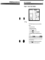
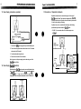
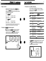
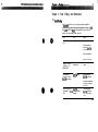
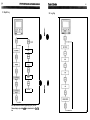
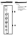
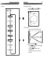
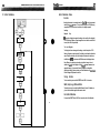
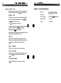
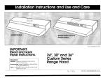
Distributed by
Any reference to Raytheon or
RTN in this manual should be
interpreted as Raymarine.
The names Raytheon and RTN
are owned by the
Raytheon Company.
MULTI
Operation and
Installation
Autohelm and SeaTalk are registered Trade Marks of Nautech Limited
Autohelms policy of continuous improvement and updating may change product specifications
without prior notice
Copyright Nautech 1993
Package Contents
The following items are included in the ST50 Plus Multi package:
1 . ST50 Plus Multi control head
2. Fixing studs (2 oftI
3. Thumb nuts (2 offl
4. Control head cover
5. Power cable
6. NMEA cable
7. Securii sticker
8. Fiing template
9. Operation and installation handbook
10. Worldwide Service Centre handbook
11. Warranty document
a
Contents
introduction .......................................................................
1
Chapter 1: Control Head Installation ......................................
3
1.1 Sing ........................................................................... 3
1.2 Mounting Procedure ...................................................... .4
1.3 Power Supply (stand-alone operation) ................................ 6
1.4 Power Supply (SeaTalk operation) ..................................... 6
1.5 Connection of Separated Instruments ................................ 7
1.6 Ring Connection ............................................................. 8
1.7 Connection to SeaTalk Compatible Autopilots ..................... .8
1.8 Connection to other Marine Equipment ............................... 9
Chapter 2: Fault Finding and Maintenance ............................
11
2.1 Fault Finding ................................................................ 11
2.2 Maintenance ................................................................ 1 2
Chapter 3: Operation ........................................................
13
3.1 Depth Key ................................................................... 1 4
3.2 Log Key.. .................................................................... 1 5
3.3 HDG Key ..................................................................... 1 6
3.4 Wind Key .................................................................... 1 8
3.5 Dead Reckoned Functions ............................................. 19
3.6 Display Contrast .......................................................... 19
Chapter 4: CODE Lock Security ..........................................
21
Chapter 5: Calibration .......................................................
25
5.1 Initial Calibration ........................................................... 26
5.2 Intermediate Calibration ............................................... .28
5.3 Extended Calibration .................................................... .29
Chapter 6: General Specification..
.......................................
31
Introduction
The ST50 Plus Multi is a powerful multifunction repeater that allows you to
display many parameters transmitted onto the SeaTalk bus by other
instruments. As well as repeating ‘live’ information, the Multi is able to
provide computed functions derived from data supplied by other SeaTalk
instruments.
The following computed functions are available with a full SeaTalk system:
(b
VMG, True Wind Direction, True Wrnd Speed, Tack Course, Distance Made
Good and Course Made Good.
The ST50 Plus Multi also incorporates a security feature to protect
instruments mounted in vulnerable areas such as the cockpit, helm
or mast.
Thank you for purchasing an Autohelm product. May we take this
opportunity to wish you years of trouble free operation.
2
Chapter 1: Control Head Installation
1lOmm (4.33in)
38.75mm (1.5in)
t------l
1.1 Sing
The ST50 Plus Multi is designed for above or below deck installation
where it is:
l
Easily read by the helmsman
l
Protected against physical damage
l
At least 230mm (gin) from a compass
l
At least 500mm (20in) from radio receiving equipment
l
Accessible from behind for ease of installation and cable running
Cation:
To prevent moisture forming on the display window, the ST!50 Plus
Multi ‘breathes’ through a small vent in the cable boss. Therefore,
the control head must be sited where the rear case is protected
from contact with water.
The rear case is ftied with a foam gasket to form a water-tight seal
between the instrument and the selected installation face.
Bracket Mounting
The ST50 Plus Multi can, as an alternative, be bracket mounted using the
Autohelm Mounting Kii (Cat. No. D130).
L
1 Cable boss 2 F&g studs 3 Thmb nuts 4 Gasket
2
1.2 Mounting Procedure
.
1. Make sure that the selected location is clean, smooth and flat.
2. Apply the self-adhesive template (supplied) to the selected location
Flush Mounting
and mark the centres for the futing studs (2) and the cable boss (1).
A flush mounting kit is available for installations where a flush mount is
required or more desirable. Full installation instructions are provided with
the kit (Cat. No. D187).
3. Drill two 4mm (5/32in) clearance holes for the fixing studs (2) through
the bulkhead. Remove the template.
4. Cut the clearance hole for the cable boss (1) using a 50mm (2in)
diameter cutter.
5. Screw the two fixing studs (2) into the control head.
6. Pass the SeaTalk cable and transducer tails through the cableboss
(1) clearance hole.
7. Assemble the control head to the bulkhead and secure from behind
using the thumb nuts (31.
Note: Because the instrument breathes through the vent in the rear case,
this bracket is for interior use only.
0
1.3 Power Supply (stand-alone operation)
1.5 Connection of Separated Instruments
Separated instruments can be connected using one of the range of
SeaTalk Extension Cables. These cables are supplied with a SeaTalk
connector fitted to each end. A junction box can be used to join the cable if
it is cut for easier routing or shortening.
If preferred, any 2 core, screened cable conforming to the following
specification may be used instead of the SeaTalk cable.
l
O
22 AWG, 2 core screened cable with a minimum copper area
of 0.5mm2.
1
1. Connect the 2m 16ft.l power supply directly to the distribution panel.
2. Cut the cable to length and connect the red wire to the + 12V terminal
and screen to the OV terminal.
3. Cut back and insulate the yellow wire.
rYellowl
4. Protect the circuit with a 5A circuit breaker.
Note: Longer runs to the power supply can be made using one of the
SeaTalk Extension Cables.
1.4 Power Supply (SeaTalk operation)
All instruments in a SeaTalk system receive power and information from
the SeaTalk bus. Each instrument has two SeaTalk connectors (3 pin) on
150mm (6in) tails. To supply power and information to the instrument
simply plug the tails from adjacent instruments into the ST50 Multi tails.
To transducer
SeaTalk tails
SeaTalk tails
il
ScreenJ
0
L Red A bcreen
ST50 Plus Multi Operatian and fmtalfatian Handbank
ChaDterl:ConWHeedhtaUaiion
1.8 Connection to other Marine Equipment
1.6 Ring Connection
The ST50 Plus Multi has an NMEA 0183 data output connector (1).
Providing it is available on the SeaTalk bus, the following information will
be transmitted every 1 to 2 seconds:
Installations with a large number of instruments on a SeaTalk bus may
require a second ringmain connection to the power supply breaker to
prevent excessive voltage drops. Whether a second ring main is required
can be determined from the following:
Cable run upto 1Om (33ft)
Single
connection:
Second connection:
13 instruments maximum
connection:
Second connection:
Content
Instrument required on
SeaTalk Bus
VWR
Apparent Wind Speed
(knots) and Direction
Wind
DBT
Depth of water below
transducer (feet)
Depth or Tridata
HDM
Magnetic Compass
Heading
Steering Compass or SeaTalk
Autopilot
HSC
Locked Magnetic Compass SeaTalk Autopilot (operating in
Auto mode)
Heading
VHW
Water Speed (knots)
Magnetic and True
Compass Heading
Speed or Tridata
Compass or SeaTalk Autopilot
GLL
Longitude and Latitude
GPS or Navdata
VTG
Course Over Ground
Speed Over Ground
GPS or Navdata
BWC
Bearing and Distance to
Wavpoint
GPS, Navdata or Navcenter
MTW
Water Temperature (deg.C)
Speed or Tridata
26 instruments maximum
Cable run upto 2Cbn (66ft)
Single
Sentence
7 instruments maximum
13 instruments maximum
The second ring-main should be connected to the spare lead on the last
instrument in the chain and directed back to the circuit breaker.
1.7 Connection to SeaTalk Compatible Autopilots
lf the installation includes a SeaTalk compatible Autopilot the ST50 Plus
instruments may be connected to the SeaTalk bus at any point. No
independent connection to the 12V power supply is necessary as the
instruments receive power from the Autopilot course computer.
To autopilot
SeaTalk BUS
Connection
I
To any further
ST50 Instruments
or Autopilot
Control Units
DLI34l
0
A lm (3ft) NMEA Interface cable (2) is supplied with the Multi. The red wire
should be connected to the signal input and the blue wire to the signal
ground (OVI of the other marine equipment. Up to two NMEA 0183
receivers may be connected to each Multi.
RED (Signal) 2
I
BLUE (Ground)
I
Chaoter 2: Fault Finding and Maintenance
Chapter 2: Fault Finding and Maintenance
2.1 FautFmding
All Autohelm products are, prior to packing and shipping, subjected to
comprehensive test and quality assurance programmes. However, if a fault
arises with the ST50 Plus Mulli, the following table will help to identify the
probable cause and provide the most likely cure.
Fault
Cause
Action
Instrument display
blank.
No supply.
Check supply.
Check cabling and
security of SeaTalk
connectors.
Check fuse/breaker.
Return unit for repair.
Instrument displays
‘CODELOCK set’,
ENTER CODE
The ‘Code Lock’ feature Enter correct code
has been set.
number.
No exchange of
information between
SeaTalk instruments.
SeaTalk cabling
problem.
Check security of
SeaTalk connectors.
Disconnect instruments
one by one to isolate
faulty unit.
Failure of a group of
instruments in SeaTalk
chain.
SeaTalk
cabling/connector
problem.
Check security of
SeaTalk connectors
and non-functioning
units.
CTM
M&i -r
thaad _..-Indslls4ku
is__. Phc
_-- __.-.-.---. _ -.-..- --__ Usndhk
..- .----. _
Chapter 3: Operation
2.2 Maintenance
Instrument
Certaii atmospheric conditions may cause condensation to form on the
conirol head window. This will not harm the instrument and can be cleared by
increasing the illumination setting to Level 3.
Chemical and abrasive materials must not be used to clean the ST50 Plus
Muiti instrument; if it is dirty, clean with a soft, damp cloth.
Cabling
Examine all cables for chafing or damage to the outer shiefd and, where
necessary, replace and resecure.
Acme
For advice, or further information regarding the installation of this product,
please contact the Autohelm product Support Deparlment or your own
National Distributor.
The ST50 Plus Multi can be connected to other ST50 instruments to
provide a fully integrated system that can be linked to any of the SeaTalk
compatible autopilots. The Multi also provides NMEA 0183 data for
navigation receivers. chart olotters or other navigational eouioment.
I
.
.
.
Note: The operational flow charts on the following pages show the
information available with a full SeaTalk system.
Units of measure follow those of the main instrument,
chaepter3: operation
3.1 Depth Key
3.2 Log Key
:I
I
1)
LIGHTS
LEVEL 3
LIGHTS
LEVEL 2
LIGHTS
LEVEL 1
LIGHTS OFF
Note: Depth alarms can be silenced by pressing any key. Also, the
Fathoms display is only availble when feet is transmitted on the SeaTalk
bus
0 \ e
I
15
16
S75OPhsMuHiOparaiimandlnstallationHandbodt
3.3 HDG Key
t’hm.tav
11. fX.ad.....
-.--. -.
-“-.“I-..
HDG Key Notes
True Heading
True headings are displayed only if variation is present on the SeaTalk bus
or set in calibration on the Multi instrument.
Distance Made Good and Course Made Good
The Distance Made Good and Course Made Good displays can be reset
by pressing and holding HDG for 4 seconds.
TRUE
HEADING
MAGNETIC
HEADING
DISTANCE MADE
GOOD DMG)
COURSE MADE
GOOD (True)
sT!5olJhlaMulb'oparauonarKlhsta~onHandbook
18
Chaptar 3: Oparatbfl
3.5 Dead Reckoned Functions
3.4 Wind Key
Distance Made Good (DMG) and Course Made Good (CMG) are dead
reckoned functions with no correction for tidal set or drii.
I
North
I
APPARENT WIND SPEED
I
BEAUFORTSCALE
I
3.6 Display Contrast
The contrast can be adjusted to achieve optimum legibility at any angle.
APPARENT WIND DIRECTION
TRUE WlND DlRECTlON Clruel
I
TRUE WIND DIRECTION (Magnetic)
1.
Momentarily press DEPTH and LOG together.
2. Press HDG or MD to increase or decrease the contrast setting (the
range being between 1 and 15).
3. Press DEPTH and LOG together momentarily to store the
contrast setting.
Note: A high setting will suit installations where the control head will be
viewed from above.
Chapter 4: CODE Lack Secwity
Chapter 4: CODE Lock Security
The ST50 Plus range incorporates an anti-theft feature called ‘CODE
Lock’. Designed to protect individual instruments or complete systems in
vulnerable areas, ‘CODE Lock is a four digit number that you programme
into the permanent memory of a selected ‘master’ instrument.
0
Note: A ‘master’ instrument is a digital unit on which the code number can
be entered, and then, if part of an integrated system, transmitted to other
ST50 Plus instruments.
e
This facility means that, should a CODE Locked instrument be removed
from the vessel without your permission, it cannot be operated without the
four digit security number.
‘CODE Lock can be used in one of three modes:
Model:Off
*
As it leaves the factory ‘CODE Lock’ is set to off. In this mode the instru
ment will operate normally when it is switched on, however, the unit will not
be protected by the anti-theft feature.
Mode 2: ‘CODE Lock’ Once-Only Entry (page 23)
This mode is designed for systems with a digital ST50 Pius instrument in a
safe, belowdecks location. This instrument can then be used as a
‘master’ to enter the four digit code number and, when the power is
switched on, automatically transmit the code to all the instruments in the
system. The advantage of this mode is that, with the master safely below
deck, code entry via the keypad is a onceonly operation on installation.
Master Unit
t Power
Once ‘CODE Lock’ is set the system operates normally as soon as the
power is switched on. In other words, the ‘CODE Lock security is invisible.
ST50 plus Multi Operadon and fnstalation Handbaak
Once Only Entry
Mode 3: ‘CODE Lock’ input at Power-On (page 24)
In the ‘Power-On mode’, the ST50 Plus is configured so that you have to
enter the four digit number on a ‘master’ digital instrument every time the
system is switched on. Until this number is entered the instrument(s)
will not operate.
This mode is particularly useful when you are unable to position a ‘master’
instrument below decks and, therefore, all the vessels valuable instrumen
tation is left in a vulnerable area.
Action
Display Shows
1
Press and DEPTH and LOG together for
4 seconds
CAL after 2 seconds and
ZO98VXX after 4 sec.
2
Press DEPTH once
CODELOCK Cal. Off
3
4 seconds after ‘CODELOCK Cal. Off
4
Press LOG
ENTER CODE
I 8
- - - -
5
Press HDG or WIND to select
first number
1 - - -
6
Press LOG to accent number
1 ‘11
7
Press HDG or WIND to select second
12--
number
8
Press LOG to accept number
1 2’-‘-
9
Press HDG or WIND to select third
number
Press LOG to accept third number
123-
11
Press HDG or WIND to select fourth
number
1234
10
IY-
Power
1 2 3’-’
12
Press LOG to accept code
‘1 2 3 4’
Should a CODE Locked instrument be removed from the system, it will not
operate until the correct four digit security number is entered or received.
13
Press LOG
PWR ON?
14
Leave PWR ON? flashing for 10 seconds
CODELOCK Cal. set
lf your selected master instrument fails for any reason, the security code
number can be entered via another ST50 Plus instrument in the system.
However, until another instrument is set as a master or the existing master
is replaced, the securii code will have to be entered every time the
system is switched on.
15
To exit CODELOCK, press DEPTH and
LOG together for 2 seconds
Normal operation
Note; A warning sticker is provided with each instrument. lf you have set 0
‘CODE Lock, position this warning sticker in a prominent location to deter
potential thieves.
l
lf you do not exit ‘CODELOCK Cal. set’ within 10 seconds the display will
change to CANCEL CODE. You now have the option of cancelling the
code, by pressing LOG to return to the __ _ _ display, or exit as de
scribed in action 15 above.
Your Code Number
Setting Up the Security Code
When the ST50 Plus Multi is switchedon for the first time the security
feature is set to off. To turn the ‘CODE Lock’ feature on, proceed
as follows:
For future reference, enter your chosen code number into the box below.
I
I
For obvious reasons, please store this handbook in a safe place.
Operation
Once only ‘CODE Lock’ entry is invisible once it has been set.
On Power-Up
Chapter 5: Calibration
Action
Display Shows
1
Press DEPTH and LOG together for 4
seconds
CAL after 2 seconds and
ZO98VX after 4 sec.
2
Press DEPTH once
CODELOCK Cal. Off
ENTER CODE
I I
- _--
3
4 seconds after ‘CODELOCK Cal. Off
4
Press LOG
5
Press HDG or WIND to select first
number
6
Press LOG to accept number
I I
1- - -
7
Press HDG or WIND to select second
number
12--
8
Press LOG to accept number
1 2’-‘-
9
Press HDG or WIND to select third
number
123s
10
Press LOG to accept third number
1 2 3’-’
11
Press HDG or WtND to select fourth
number
1234
12
Press LOG to accept code
‘1234
1- - -
13 Press LOG
PWR ON?
14
Press LOG within 10 seconds
CODELOCK Cal. set
15
To exit CODELOCK, press DEPTH and
LOG together for 2 seconds
Normal operation
ff you do not exit ‘CODELOCK Cal. set’ within 10 seconds the display will
change to CANCEL CODE. You now have the option of cancelling the
code, by pressing LOG to return to the __ __ display, or exit as de
scribed in action 15 above.
Your Code Number
For future reference, enter your chosen code number into the box below.
For obvious reasons, please store this handbook in a safe place.
Operation
When the unit is powered on you are prompted to enter the code number.
To enter the number, carry out actions 4 to 12 above and press LOG.
The ST50 Plus Multi can be adjusted to suit your particular requirements
using the initial, intermediate and extended calibration menus described in
this section.
Chapter 5: Calibration
26
27
Initial Calibration Notes
5.1 Initial Calibration
Variation
Heading information is transmitted onto the SeaTalk bus by the instrument
reading the fluxgate compass. This can be the Autopilot or ST50 Steering
compass which, in either case, should be set to display magnetic
headings.
Magnetic
t
lf you want to display just magnetic headings on the multi, set the Autopilot
or ST50 Steering Compass to read magnetic and set variation on the Multi
to zero (this is the factory default).
I)
CAL
Only
True and Magnetic
VAR!ATlON
.
Note; When set to display true headings, significant changes in local
variation will after the true display as the fluxgate compass measures the
magnetic heading. If you want the Steering Compass or Autopilot to
display true heading, please contact your local distributor or the Autohelm
Product Support Department for advice.
MULTI
I
To display both true and magnetic headings, set the Autopilot or ST50
Steering Compass to read magnetic. If available in the Autopilot calibration
menu, Variation should be set on the Autopilot. Otherwise set variation on
the Multi using WIND to increase and HDG decrease the displayed value.
t
Storing Variation
DEPTH
To store variation, press and hold DEPTH and LOG for 2 seconds.
Multi, Depth, Log, HDG and Wind
LOG
B
0
These functions are for use with the Multi Remote Control. Full details are
given in the handbook supplied with remote control.
Exii Initial Calibration
Press and hold DEPTH and LOG for 2 seconds to exit initial calibration.
HDG
28
cha.ptar5: calfe
5.2 Intermediate Calibration
5.3 Extended Calibration
29
BUS TRUE
OR MAGNATIC
Intermediate Calibration Notes
Refer to Chapter 4 for full details on the securkity feature.
To exit intermediate calibration, press and hold DEPTH and LOG together
for 2 seconds.
Exit Intermediate Calibration
Press and hold DEPTH and LOG for 2 seconds to exit intermediate
calibration.
REMOTE
TRANSMISSION
ST50 plus Multi Of)eration and lrstalfatjon Handbook
Extended
Calibration
Notes
With the exception of the damping menus, which are adjusted using HDG
and/or WIND, the following options are modified using the WIND key.
Calibration
On/Off
Calibration allows you to protect your selected settings. When calibration
is enabled the initial and intermediate calibration cannot be modiiied.
CAL 0 = Calibration locked, i.e. no access
CAL 1 = Calibration unlocked, i.e. normal access
Once locked calibration can be unlocked by entering extended calibration
and selecting 1, calibration unlocked (the factory default is 1).
Damping (Speed, VMG and True Wind)
Damping adjusts the averaging applied to the displayed dated. The default
setting is 4, however, the range is between 1 and 15.
Boat Show
Boat Show mode is a dealer demonstration program only. Under no
circumstances must this program be engaged when this unit is installed
on-board your vessel. The display must, therefore, be left set to
‘BSHOW 0’.
Remote
Transmission
The ‘MULTI’ option is for future use only and should be set to 1.
Bus (True or Magnetic)
This option is set to true or magnetic, depending on whether the information on the SeaTalk bus is true or magnetic (the factory default is
magnetic).
Exit Extended Calibration
Press and hold DEPTH and LOG for 2 seconds to exit extended
calibration.
Chapter 6: General SpecScation
Chapter 6: General Specification
Dimensions:
110xllOmm(4.33x4.33in)
Power supply:
10 to 16V
Power consumption:
30ma (normal) lOOma (illumination on)
Temperature range:
0 to 70 deg.C
Illumination:
3 levels plus off