1
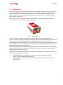
DVTEL INC. 65 Challenger Road Ridgefield Park, NJ 07660 IOI-XTRK-10D Installation Manual The contents of this guide may not be reproduced or reprinted in whole or in part without the express written permission of DVTEL, INC. April 2013 IOI-XTRK-10D Installation Manual Table of Contents 1 Document Information.................................................................................................... iv 2 Introduction ................................................................................................................... 1 2.1 Items Included in the Package .................................................................................... 2 2.2 Hardware Overview .................................................................................................... 3 2.3 Relay Outputs ............................................................................................................. 4 2.4 RS485 Control Connection .......................................................................................... 4 3 Workflows ...................................................................................................................... 6 3.1 Pre-Installation Workflow ........................................................................................... 6 3.2 Installation Workflow ................................................................................................. 7 3.3 Post-Installation ......................................................................................................... 7 4 Installation ..................................................................................................................... 8 4.1 Indoor and Outdoor Installation Considerations ......................................................... 8 4.1.1 Indoor Installation .................................................................................................. 8 4.1.2 Outdoor Installation ............................................................................................... 8 4.2 5 Cabling ....................................................................................................................... 9 4.2.1 Video Cable ............................................................................................................ 9 4.2.2 Electrical/Power Supply Cables ............................................................................. 10 4.2.3 Electrical Power Input .......................................................................................... 11 Connections and Configuration ......................................................................................13 5.1 Connecting the Encoder ........................................................................................... 13 5.1.1 Connecting the Camera to the Encoder ................................................................ 14 5.1.2 Connecting the Unit to Control an External Device (Using Relay Outputs) ............. 15 5.1.3 Connecting the Encoder’s Video Output to an Analog Device ............................... 17 5.1.4 Connecting a Microphone to the Unit ................................................................... 17 5.1.5 Connecting a Loudspeaker to the Unit .................................................................. 18 5.1.6 Grounding the Unit .............................................................................................. 18 5.1.7 Connecting the Unit to the Power Supply ............................................................. 19 5.1.8 Connecting the Encoder to the Network ............................................................... 19 5.2 5.3 5.4 Configuring the Encoder’s Network IP Settings ......................................................... 19 Configuring Camera Settings via the Encoder ............................................................ 20 Resetting the Encoder .............................................................................................. 20 5.4.1 Reset Using the RESET Button .............................................................................. 20 5.4.2 Reset by Removing the Power Supply ................................................................... 21 5.5 Solo Setup ................................................................................................................ 21 i IOI-XTRK-10D Installation Manual Appendix .............................................................................................................................22 A.1. Technical Specifications ............................................................................................ 23 A.2. Connecting Leads to a Spring Clamp Terminal Block ................................................. 25 A.3. Solo Setup Window .................................................................................................. 26 A.4. Troubleshooting ....................................................................................................... 29 Contacting DVTEL .................................................................................................................32 ii Document Information List of Figures Figure 1 - IOI-XTRK-10D Unit ................................................................................................................... 1 Figure 2 - System Schematic .................................................................................................................... 2 Figure 3 - IOI-XTRK-10D Front Panel ....................................................................................................... 3 Figure 4 - Power Input Terminal ................................................................................................................ 4 Figure 5 - Terminal Block Electrical Polarity ............................................................................................ 12 Figure 6 - System Cable .......................................................................................................................... 14 Figure 7 - Encoder-to-Camera Two-Wire Cable ...................................................................................... 15 Figure 8 - Relay Contact Schematic ........................................................................................................ 16 Figure 9 - Microphone Connection to the Unit ......................................................................................... 17 Figure 10 - Loudspeaker Connection to the Unit ..................................................................................... 18 Figure 11 - Type & Model Setup Window ................................................................................................ 20 Figure 12 - Installed Terminal Block Connector ...................................................................................... 25 Figure 13 - Connecting a Wire to a Terminal Block ................................................................................. 25 Figure 14 - Solo Setup Window ............................................................................................................... 26 iii IOI-XTRK-10D Installation Manual 1 Document Information Document Scope and Purpose The purpose of this document is to provide instructions and installation procedures for physically connecting the IOI-XTRK-10D encoder. After completing the physical installation, additional setup and configurations are required before video analysis and detection can commence. For information on the unit setup and configuration, refer to the HTML Edition Units User’s Guide. Note: This document is intended for use by technical users who have a basic understanding of CCTV camera/video equipment and LAN/WAN network connections. Warning: Installation must follow safety, standards, and electrical codes as well as the laws that apply where the units are being installed. Proprietary Rights and Non-Disclosure This manual is delivered subject to the following restrictions and conditions: This document contains proprietary information belonging to DVTEL, Inc. This information is supplied solely for the purpose of assisting explicitly the licensee of the DVTEL units. No part of this document contents may be used for any other purpose, disclosed to any third party or reproduced by any means, electronic or mechanical, without the express prior written permission of DVTEL, Inc. Trademarks and Copyrights DVTEL, the DVTEL logo, ioimage, the ioimage logo, ioimage analytics, ioibox, ioicam, ioiware, ioiware command center, ioiware setup, CP-2202-361P/N, IOI-XTRK-10D, IOI-XTRK-100D, trk1, trk10d, trk100, trk100d, trk-101, trk200, trk4000d, trk8000, mmp100dn, sc1dn-A, XPVA-10D, and XPVA100D are trademarks of DVTEL, Inc. Products and trademarks mentioned herein are for identification purposes only and may be registered trademarks of their respective companies. DVTEL, Inc. makes no representations whatsoever about any other products or trademarks mentioned in the manual. This manual and its contents herein are owned by DVTEL, Inc. © 2013 DVTEL, Inc. All rights reserved. iv Document Information Disclaimer Users of DVTEL products accept full responsibility for ensuring the suitability and considering the role of the product detection capabilities and their limitation as they apply to their unique site requirements. DVTEL, Inc. and its agents make no guarantees or warranties to the suitability for the users’ intended use. DVTEL, Inc. accepts no responsibility for improper use or incomplete security and safety measures. Failure in part or in whole of the installer, owner, or user in any way to follow the prescribed procedures or to heed WARNINGS and CAUTIONS shall absolve DVTEL, Inc. and its agents from any resulting liability. Specifications and information in this guide are subject to change without notice. Document Conventions WARNING and CAUTION notes are distributed throughout this document, whenever applicable, to alert you of potentially hazardous situations. These may be hazards associated with a task or a procedure you are carrying out or are about to carry out. The following document conventions are used throughout this manual: A Warning is a precautionary message that indicates a procedure or condition where there are potential hazards of personal injury or death. A Caution is a precautionary message that indicates a procedure or condition where there are potential hazards of permanent damage to the equipment and or loss of data. A Note is useful information to prevent problems, help with successful installation, or to provide additional understanding of the products and installation. A Tip is information and best practices that are useful or provide some benefit for installation and use of ioimage products. General Cautions and Warnings This section contains information that indicates a procedure or condition where there are potential hazards. These may be hazards associated with a task or procedure a user is carrying out or about to carry out. WARNINGS and CAUTIONS are distributed throughout this document, whenever applicable, to alert the user of potentially hazardous situations. SAVE ALL SAFETY AND OPERATING INSTRUCTIONS FOR FUTURE USE. Although the unit is designed and manufactured in compliance with all applicable safety standards, certain hazards are present during the installation of this equipment. v IOI-XTRK-10D Installation Manual To help ensure safety and to help reduce risk of injury or damage, observe the following: Warning: 1. Only qualified trained personnel should service and repair this equipment. 2. Observe local codes and laws and ensure that installation and operation are in accordance with fire, security and safety standards. Electrical Safety Notice and Warnings Warning: 1. Read the installation instructions before you connect the unit to a power source. 2. Electrical safety should always be observed. All electrical connections must be performed by a certified electrician. 3. If you use an extension cord with this system, make sure that the total ampere rating on the products plugged into the extension cord does not exceed the extension cord ampere rating. 4. To avoid possible shock hazards or damaging the unit, ensure that the positive and negative of the power leads are properly connected to the terminal block connector before plugging it into the unit or turning on the power source. 5. In the following situations, the electric power should be turned off immediately and appropriate repairs, replacements or remedies should be taken if: The power line is damaged, frayed or shows heavy wear. The unit has been physically crushed or deformed. The unit has been exposed to water. The unit has been exposed to, or shows signs of damage from, fire, intense heat, heavy smoke, fumes, or vapors. Electrical connections of the unit become abnormally hot or generate smoke. The unit has been dropped, damaged or shows signs of loose internal parts. The unit does not operate properly. Caution: To avoid damage from overheating or unit failure, ensure that there is sufficient temperature regulation to support the unit’s requirements (cooling/heating). Operating temperature should be kept in the range 0° to 50°C (32° to 122°F), with no more than 95% non-condensing humidity. vi Document Information Minimizing EMI and RFI When wires run for a significant distance in an electromagnetic field, electromagnetic interference (EMI) can occur. Strong EMI (e.g. lightning or radio transmitters) can destroy the units and can pose an electrical hazard by conducting power through lines and into the system. Poor quality or worn wiring can result in radio frequency interference (RFI). To minimize the effects of EMI and RFI, consult your reseller. Site Preparation There are several requirements that should be properly addressed prior to installation at the site. The following specifications are requirements for proper installation and operation of the unit: Ambient Environment Conditions: Avoid positioning the unit near heaters or heating system outputs. Avoid exposure to direct sunlight. Use proper maintenance to ensure that the unit is free from dust, dirt, smoke, particles, chemicals, smoke, water or water condensation, and exposure to EMI. Accessibility: The location used should allow easy access to unit connections and cables. Safety: Cables and electrical cords should be routed in a manner that prevents safety hazards, such as from tripping, wire fraying, overheating, etc. Ensure that nothing rests on the unit’s cables or power cords. Ample Air Circulation: Leave enough space around the unit to allow free air circulation. Cabling Considerations: Units should be placed in locations that are optimal for the type of video cabling used between the unit and the cameras and external devices. Using a cable longer than the manufacturer’s specifications for optimal video signal may result in degradation of color and video parameters. Physical Security: The unit provides threat detection for physical security systems. In order to ensure that the unit cannot be disabled or tampered with, the system should be installed with security measures regarding physical access by trusted and un-trusted parties. Network Security: The unit transmits over IP to security personnel for video surveillance. Proper network security measures should be in place to ensure networks remain operating and free from malicious interference. The unit is intended for installation on the backbone of a trusted network. Electrostatic Safeguards: The unit as well as other equipment connected to it (relay outputs, alarm inputs, racks, carpeting, etc) shall be properly grounded to prevent electrostatic discharge. The physical installation of the unit is the first phase of making the unit operational in a security plan. The goal is to physically place the unit, connect it to other devices in the system, and to establish network connectivity. When finished with the physical installation, refer to the HTML Edition Units User’s Guide to complete the second phase of installation, which is the setup and configuration of the unit. vii Introduction 2 Introduction The IOI-XTRK-10D is a self-contained video analytic IP encoder that monitors the video input from a camera, providing real-time detection and autonomous tracking capabilities. Operators can define rules, perimeter lines, sterile zones and other criteria for intrusion detection. In addition to its analytic capabilities, the IOI-XTRK-10D also transforms the input video to a standards-compliant, compressed IP video stream. The encoder converts an ordinary analog PTZ camera into an intelligent camera that identifies threats, tracks intruders, and takes action automatically. Figure 1 - IOI-XTRK-10D Unit The unit analyzes the captured video signal, generates alarms, and notifies operators of the presence of people, vehicles or objects. It can stop and detect events in multiple preset zones. Users can define the events and location in the video of the image that can be detected with usercustomizable rules and positioning criteria. The camera simultaneously provides video output in two formats: analog video and compressed digital video over IP. On-screen overlays indicate where the detection has occurred on the video output. The IOI-XTRK-10D contains an embedded digital signal processor (DSP) chip that includes intelligentvideo analysis and tracking software for running algorithms, real-time audio, and MPEG 4 SP and MJPEG video encoding and streaming. The DSP may be configured through the IP connection of the IOI-XTRK-10D in order activate the unit and set the following analytic functions: Intrusion Detection - for detecting intruder scenarios including detection within a region, tripwire and fence breach detection PTZ Tracking - for transforming the pan/tilt/zoom camera into a self-directed intruder tracking system 1 IOI-XTRK-10D Installation Manual As part of the ioimage intelligent video cameras series, the IOI-XTRK-10D‘s analog and IP streaming video outputs enable connectivity to both legacy analog DVR and IP-based network video management systems. The camera can be configured and setup via Internet Explorer 8 or 9 within a few minutes. Figure 2 - System Schematic 2.1 Items Included in the Package The IOI-XTRK-10D package contains the following: QTY Description 1 IOI-XTRK-10D encoder 1 Terminal block spring clamp connectors for relay output, ground, and RS485 wire termination 1 Terminal block connector for power connection 1 Audio splitter cable (stereo 3.5mm jack plug into two mono lines) 1 PoE injector 1 Documentation and utilities CD Related Documentation: 2 XPVA-10D/100D Installation Guide CP-2202-361P/N User and Installation Guide HTML Edition Units User’s Guide Introduction 2.2 Hardware Overview This section provides a short description of the IOI-XTRK-10D front panel connections and features. Figure 3 - IOI-XTRK-10D Front Panel # Feature Description 1 Terminal block port 1 The terminal block includes: Inputs for connecting the RS485 control wires between the camera and the encoder (T+ and T-). Additional ground connection. 2 ETHERNET 802.3af PoE port Port for connecting a PoE injector or an Ethernet cable to a 10/100 Mbps Ethernet Local Area Network. 3 AUDIO IN/OUT (Plug) 3.5 mm stereo audio interface to/from the unit. The plug requires a splitter cable (supplied by DVTEL) to separate the audio input and output signals. 4 VIDEO IN Video input for receiving analog video signal from the CP-2202-361P/N camera. 5 RESET Small opening that allows access to the RESET button. Resets the unit’s internal firmware to the previous settings. 6 24V/12-24 The power outlet for plugging in (terminal block connection) the power from a properly rated power source. Enables remote listening to the sounds captured by a microphone connected to the unit through this interface. Audio Input: Enables remote listening to the sounds captured by a microphone connected to this plug on the IOI-XTRK-10D unit. See Connecting a Microphone to the Unit (page 17). Audio Output: Enables talking to people near the camera being monitored via an amplified loudspeaker that is connected to this plug on the IOI-XTRK-10D unit. See Connecting a Loudspeaker to the Unit (page 18). 3 IOI-XTRK-10D Installation Manual Figure 4 - Power Input Terminal 7 Terminal block port 2 The terminal block includes a relay output, which supports output of optoisolated signal for a single external device, such as an electrical door lock relay. - NO: Terminal for NORMALLY OPEN configurations - COM: Terminal for COMMON wire configurations for either NC or NO - NC: Terminal for NORMALLY CLOSED configurations For more information, see Connecting the Unit to Control an External Device (Using Relay Outputs) (page 15). 8 VIDEO OUT Video output for transmitting analog video signal to an analog video display or analog video recording device. You can connect an analog monitor to view real-time video of the camera. 9 GND (Ground) External terminal on rear panel. See Grounding the Unit (page 18). 2.3 Relay Outputs An external device, such as an electric door lock, can be connected to the RELAY terminal block of the unit. In response to events such as poor visibility, signals can be sent to operate the external device. Caution : 1. To avoid damage to the system and system interference, a certified electrician must ensure that the ground voltage is comparable (ground loops) among all connected system components. 2. Consideration and care needs to be given regarding how the security officers will reset, command, and override incident responses. For example, if the system detects someone walking in a detection zone and automatically executes a lockdown, security officers may need a bypass for the lockdown. 2.4 RS485 Control Connection The encoder supports one RS485 connection, which is used to control the camera. The RS485 connection to the unit is made through the TX+ and TX- lead wires on the camera’s System Cable. Once connected, the PTZ camera can be remotely controlled from within the HTML Live View and HTML setup application using its built-in PTZ Remote Control Panel. For more information, see Connecting the Camera’s PTZ Control Line to the Encoder (page 15). 4 Introduction Warning: The RS485 standard specifies an input voltage range between -7V to +12V. Exceeding this voltage can cause permanent damage to the unit. 5 IOI-XTRK-10D Installation Manual 3 Workflows The following are general workflows for installation as well as pre- and post-installation steps. The workflows are only guidelines. Individual installation may require variations based on the needs of the site. This section contains the following sections: Pre-Installation Workflow Installation Workflow Post-Installation 3.1 Pre-Installation Workflow Install electrical infrastructure (conduit, electrical wiring, boxes, breakers, grounded outlets, switches, UPS, surge protector, grounds, etc.). Establish or install LAN/WAN network access for unit location (network wiring, ports, wireless, Wireless Access Points, etc.). Install wiring between interfaces to external devices (relay outputs) and the unit location. Install wiring for audio input and output devices (microphone/audio system) and the unit location. Install video monitors and the wiring to connect to the unit location. Install wiring between PTZ controller leads and the unit location. Connect the workstation computer to the network. Tip: 1. The unit is delivered from manufacture with a pre-configured IP address. Change the pre-configured IP address to match your network IP mapping before connecting the unit to the network. 2. It is possible to access the HTML setup menu in the unit by connecting from a laptop/PC directly to the unit using a network cable and typing the IP address in a web browser (32-bit version of Internet Explorer 8 or 9 only). 6 Workflows 3.2 Installation Workflow Write down the unit’s IP address. Assemble the video cameras, associate equipment, and unit in the camera casing. Connect necessary internal wiring among the associated devices. Mount the video unit (includes mounting brackets, casing, camera, and encoder.) Note: Ensure necessary cooling, shelter and ventilation to maintain proper ambient environment. Connect the infrastructure wiring to the devices inside the camera casing, including the unit to network, audio, video, relay output, power, RS485, etc. Note which cameras and external devices connections (relay outputs) are connected with descriptions. Note the camera model, as well as which cameras are PTZ and which are stationary. Turn on the cameras, matrix switcher, monitors as well as any external devices (connected to the IOI-XTRK-10D unit through relay outputs). Access the unit using the 32-bit version of Internet Explorer 8 or 9. If you need to make changes to the unit’s network settings, access the unit IP and make changes in the setup area of the HTML Edition Setup (IP, Submask and Gateway). Note: In order for the IOI-XTRK-10D to detect and track, the channel must be armed with an active rule defined in the setup. For more information, refer to the HTML Edition Units User’s Guide. 3.3 Post-Installation The following general workflow outlines the tasks that will need to be done after installing the unit. These post-installation procedures are mentioned in this document but are covered in greater detail in the HTML Edition Units User’s Guide. Please refer to that guide for more detail. Configure the IOI-XTRK-10D via its built-in HTML setup application. Configure the unit and camera including relay outputs, etc. For more information, refer to the HTML Edition Units User’s Guide. Connect monitoring computers with a supported web browser or supported RTSP device. If using analog only connect to the analog monitors. 7 IOI-XTRK-10D Installation Manual 4 Installation 4.1 Indoor and Outdoor Installation Considerations The following sections provide insight and key information that should be considered when installing the cabling for the IOI-XTRK-10D: Indoor Installation Outdoor Installation Caution: To avoid damage from overheating or unit failure, ensure that there is sufficient temperature regulation to support the unit’s requirements (cooling/heating). Operating temperature should be kept in the range 0° to 50°C (32° to 122°F), with no more than 95% non-condensing humidity. 4.1.1 Indoor Installation Following are additional consideration for an indoor installation. There must be a fuse or circuit breaker at the starting point of the electrical wiring infrastructure. For indoor installations, such as industrial installations, the unit must be protected from elements such as damaging fumes, metallic dust, extreme temperatures, soot, moisture, overspray, etc. The unit should not be placed near or on radiators and heat sources. 4.1.2 Outdoor Installation Following are additional consideration for an outdoor installation. 8 For any outside wiring installation, always use weatherproof equipment, such as boxes, receptacles, connectors, etc. For electrical wiring, use properly rated sheathed cables for conditions which the cable will be exposed to (e.g. moisture, heat, UV, physical requirements, etc.). The unit must be protected from weather conditions. Units should be installed within secure weatherproof casings, such as camera shrouds, housings, etc. Plan ahead to determine where to install weatherproof outlet boxes and unit storage. Whenever possible, ground weatherproof boxes to an outdoor ground. Outdoor boxes should provide some form of a security locking mechanism. Look for an enclosure/casing suited for protecting the unit as needed for your installation environment. We recommended that a rating of IP65/NEMA 4 or greater be used. The following table provides National Electrical Manufacturers Association (NEMA) and Institute of Petroleum ratings. These are US and European ratings that indicate an enclosure’s ability to withstand certain environmental conditions: Installation Rating Description IP54/NEMA 2 Protected against splashing water and the ingress of most dust. IP65/NEMA 4 Completely protected against the ingress of dust and against low pressure water jets from all directions, (limited ingress permitted), and to be undamaged by the formation of ice on the enclosure. IP66/NEMA 4X Completely protected against the ingress of dust and against high pressure jets from all directions, (limited ingress permitted), to be undamaged by the formation of ice on the enclosure with the added benefit of being corrosion proof. IP67/NEMA 6 Temporary immersion in water (15-100 cm/6-39 inches) and completely protected against the ingress of dust, and to be undamaged by the formation of ice on the enclosure. 4.2 Cabling Cabling should be routed for the shortest path and minimizing impedance. Cabling routes should be planned for the fewest bends. Avoid unnecessary connections and use only approved connectors in locations that provide accessibility. This section discusses different considerations for the different cabling types: Video Cable Electrical/Power Supply Cables Electrical Power Input 4.2.1 Video Cable Use the appropriate connectors for indoor outdoor cabling. Cables should be maintained at scheduled intervals, connections should be secured. Worn or damaged cables should be replaced to ensure optimally low impedance. Recommended Cable Specifications: 75Ω coaxial cable impedance Note: Using a cable longer than the manufacturer’s specifications for optimal video signal may result in degradation of color and video parameters. Caution: To avoid damage to the system and system interference, a certified electrician must ensure that the ground voltage (ground loops and foreign stray voltage) is comparable among all connected system components. Shielding of video cables and equipment racks, as well as a ground isolation transformer, may be required to solve ground loop problems. This relates to all grounded devices. 9 IOI-XTRK-10D Installation Manual 4.2.2 Electrical/Power Supply Cables Warning: 1. To prevent bodily injury or possible death, shut off the electrical current at the main switch before tying-in wiring. 2. Make sure that the product is properly grounded when in use. The following should be considered for electrical wiring and cables: 10 Electrical cabling must contain a grounding conductor. All electrical components and devices must be grounded for complete safety, especially for outdoor installations. To help prevent electric shock, a power supply used should be connected to a properly grounded electrical outlet. Electrical cords with threeprong plugs help to ensure grounding. Do not use adapter plugs or remove the grounding prong from a cable. Many local codes now require outdoor electrical circuits to be protected with GFIs (Ground Fault Interrupters). Check your local code. GFIs are required in most areas for outdoor circuits. Follow the manufacturer's instructions for the installation of the type of GFI you decide to use. Ensure that power cables are rated for the unit’s voltage and current requirements. The voltage and current rating of the cable should be greater than the unit’s ratings defined in this guide and marked on the product. To help protect the unit and connected system components from sudden, transient increases and decreases in electrical power, use a surge suppressor, line conditioner, or uninterruptible power supply (UPS). For underground wiring, always bury an underground cable at least 18" (457 mm) deep. Twenty-four inches (610 mm) is preferable, since cables buried at this depth are less likely to be disturbed or dug up. Always use at least type UF sheathed cables for installations requiring underground electrical wiring. There must be a fuse or breaker at the starting point of the electrical wiring installation. Installation 4.2.3 Electrical Power Input The unit must have the external protective earth terminal permanently connected to protective earth according to local regulations and codes. For more information, see Grounding the Unit (page 18). The protective grounding conductor should be aluminum. The lug of the protective grounding conductor should be aluminum; washers and screws should be Hi Cr stainless steel, 12% Cr stainless steel, Chromium on steel, Nickel on steel, tin, or steel. External protective earth stud must be permanently connected to the protective earth. This device must be installed according to the latest version of the country’s electric codes. For North America, equipment must be installed in accordance to the applicable requirements in the US National Electrical Code and the Canadian Electrical Code. Select a power supply cord that is UL Listed and CSA Certified: o Three-conductor o 18 AWG o Terminated in a molded-on plug cap o Rated 125V,15A o Minimum length of 1.5 m (4.9 feet) but no longer than 4.5 m (14.8 feet) A limited power source (LPS) must be used. There are two options for powering the unit: o Power over Ethernet (PoE) injector (supplied by DVTEL) o Connection to the power leads (available as an accessory) 4.2.3.1 Power over Ethernet (PoE) The IEEE 802.3af Power over Ethernet (PoE) standard requires that the network wiring is injected with power. DVTEL supplies with the package a limited power source PoE injector that conforms to standard. The IOI-XTRK-10D accepts DC power over the unshielded twisted-pair 10/100 Ethernet wiring. It works with existing cables, including Category 3, 5, 5e, or 6. Pin-out of the spare twisted pairs is as follows: Terminal Pins Positive 4 and 5 Negative 7 and 8 11 IOI-XTRK-10D Installation Manual 4.2.3.1.1 Power Sourcing Equipment The power sourcing equipment (PSE) ensures that no damage can occur to any equipment on the network. The PSE first looks for devices that comply with the IEEE 802.3af specification. This is achieved by applying a small current-limited voltage to the cable. The PSE then checks for the presence of a 25k ohm resistor in the remote device. If this load or resistor is detected, 48V is applied to the cable, but it is still current-limited to prevent damage to cables and equipment under fault conditions. The PSE will continue to supply power until the encoder (the powered device) is removed or it stops drawing its minimum current. 4.2.3.1.2 The Encoder as a Powered Device The encoder must be able to operate within the confines of the Power over Ethernet specification. It receives a nominal 48V from the cable, and must be able to accept power from the spare twisted pair or from data cables. Because the supplied 48 volts is too high to power the electronics, an isolated DC-DC converter is used to transform the 48V to a lower voltage. This also enables 1,500V isolation to be provided for safety reasons. 4.2.3.2 Power on Terminal Block Connector Following is an illustration of the power connection on the unit’s front panel. Figure 5 - Terminal Block Electrical Polarity The power supply specification for the IOI-XTRK-10D is 12-24 VDC or 24 VAC. Caution: Always use a properly rated external power supply. Make certain the power supply used meets the unit’s specifications. Note: The DSP chip embedded in the unit uses flash memory, which stores configuration settings even when the unit is not powered. 12 Connections and Configuration 5 Connections and Configuration Installation of the encoder requires several steps described in the following sections: Connecting the Encoder (page 13) Configuring the Encoder’s Network IP Settings (page 19) Configuring Camera Settings via the Encoder (page 20) Resetting the Encoder (page 20) Solo Setup (page 21) 5.1 Connecting the Encoder This section contains the following topics: Connecting the Camera to the Encoder (page 14) Connecting the Unit to Control an External Device (Using Relay Outputs) (page 15) Connecting the Encoder’s Video Output to an Analog Device (page 17) Connecting a Microphone to the Unit (page 17) Connecting a Loudspeaker to the Unit (page 18) Grounding the Unit (page 18) Connecting the Unit to the Power Supply (page 19) Connecting the Encoder to the Network (page 19) 13 IOI-XTRK-10D Installation Manual 5.1.1 Connecting the Camera to the Encoder The System Cable supplied with the CP-2202-361P/N PTZ camera connects the IOI-XTRK-10D encoder to the camera’s video output and RS485 control line. The following illustration shows the System Cable: Figure 6 - System Cable 5.1.1.1 Connecting the Video Output of the Camera to the Encoder To connect the video output of the PTZ camera to the encoder Attach one end of a 75Ω coaxial cable with female BNC connectors (not supplied by DVTEL) to the VIDEO IN connector on the IOI-XTRK-10D. Note: The cable length may not exceed 30 meters (98 feet) in length. For more information on video cable specifications, see Video Cable (page 9). Attach the other end to the male BNC connector on the System Cable. Note: You must connect the RS485 control lines of the PTZ camera in order to use the camera’s pan, tilt, and zoom functions. 14 Connections and Configuration 5.1.1.2 Connecting the Camera’s PTZ Control Line to the Encoder Use a two-wire 24 AWG cable (not supplied by DVTEL) to enable the RS485 control connection between the encoder and the camera. The cable attaches the terminal block connector on the encoder’s RS232/485 port to the terminal block connector on the System Cable’s RS485 PTZ control wires, according to the following illustration: Figure 7 - Encoder-to-Camera Two-Wire Cable Note: The two-wire cable is not supplied by DVTEL and should be supplied by the installer. To connect the RS485 PTZ control line between the camera and encoder 1. Connect one end of the two-wire cable to the “D+” and “D-“ terminals (pins 1 and 2) on the male 5-pin terminal block connector supplied with the encoder. 2. Insert the male 5-pin terminal block connector into the female terminal block connector on the encoder, so that the “T+” and “T-“ terminals on the encoder align with the “D+” and “D-“ wires on the two-wire cable’s terminal block. See Figure 3 - IOI-XTRK-10D Front Panel. 3. Connect the other end of the two-wire cable to the “D+” and “D-” terminals (pins 1 and 5) on the male 5-pin terminal block connector supplied with the System Cable. 4. Insert the male 5-pin terminal block connector into the female 5-pin terminal block connector attached to the System Cable. 5.1.2 Connecting the Unit to Control an External Device (Using Relay Outputs) External devices can be connected to the NORMALLY OPEN or NORMALLY CLOSED relay outputs of the unit in order to enable a specific incident response or to automatically control a device via the encoder in case of events such as intruder detection, poor signal, low visibility, etc. For example, if an intruder is detected in a courtyard, as an automatic incident response exit doors are locked and security shutters are closed. For more information on incident responses and relay outputs, refer to the HTML Edition Units User’s Guide. 15 IOI-XTRK-10D Installation Manual Relay Output Specifications Maximum current 1A @ 24VDC Maximum current 0.5A @ 125VAC 5.1.2.1 Relay Contact Schematic Figure 8 - Relay Contact Schematic NC: Terminal for connecting one of a pair of wires that leads to an external device on a circuit configured for NORMALLY CLOSED C: Terminal for connecting the second of a pair of wires for the COMMON lead of an external device regardless of whether the device is operated in a NORMALLY OPEN or NORMALLY CLOSED configuration NO: Terminal for connecting one of a pair of wires that leads to an external device on a circuit configured for NORMALLY OPEN A relay output terminal has two options for connecting a device: Option 1: NORMALLY CLOSED configuration Option 2: NORMALLY OPEN configuration The relay output supports an opto-isolated signal for a single external device, such as an electrical door lock relay. Signals can be sent as continuous (ON/OFF) or single pulse of predefined duration. To connect a device controller to the unit’s relay output 1. Connect the leads from the external device controller to the respective terminal points on the spring clamp terminal block according to your requirements (NORMALLY OPEN or NORMALLY CLOSED configuration). See Connecting Leads to a Spring Clamp Terminal Block (page 25) in the Appendix. 2. Insert the terminal block into the RELAY port on the front panel of the unit. See Figure 3 - IOI-XTRK-10D Front Panel (page 3). 3. Connect the other end of the cable to the external device, which receives the signal from the unit and controls/powers the external device. Caution: 1. To prevent damage to the unit, do not exceed the voltage and current ratings for relay terminals. 2. To avoid damage to the system and system interference, a certified electrician must ensure that the ground voltage (ground loops) is comparable among all connected system components. 16 Connections and Configuration 5.1.3 Connecting the Encoder’s Video Output to an Analog Device The encoder’s analog video output can be monitored or recorded on analog devices. The output analog video contains the video from the camera combined with On-Screen Display (OSD) overlays such as tracking boxes and trails, time stamp, alarm, camera status, etc. These OSD overlays can be enabled and customized using the HTML setup application. For more information, refer to the HTML Edition Units User’s Guide. To connect an analog device to the encoder’s analog video output Using a 75Ω coax cable, connect the VIDEO OUT of the IOI-XTRK-10D to the analog device’s video input (e.g. the VIDEO IN of a monitor). 5.1.4 Connecting a Microphone to the Unit You can connect an audio input device, such as a microphone, to the unit in order to listen remotely to sounds near the camera. You also can connect a separate audio input device for each camera channel. Figure 9 - Microphone Connection to the Unit The audio input to the unit is connected to a LINE IN interface and must meet the following specifications: Input impedance: 10k Ω Input capacitance: 30 pF Maximum input level: 2 Vrms Minimum detectable input level: 20 mVrms To connect a microphone to the unit 1. Connect the supplied audio splitter cable to the AUDIO IN/OUT port located on the front panel of the unit. See Figure 3 - IOI-XTRK-10D Front Panel (page 3). 2. Connect the audio device (microphone/amplifier) at the other end of the audio splitter cable to the AUDIO INPUT RCA connector. 3. Connect the microphone to the amplifier. 17 IOI-XTRK-10D Installation Manual 5.1.5 Connecting a Loudspeaker to the Unit Use the supplied audio splitter cable to connect a loudspeaker to the unit and make announcements near the camera from a microphone connected to the Video Management System PC. The audio output from the unit provides Line Out levels. An amplifier must be used to drive the loudspeakers. Figure 10 - Loudspeaker Connection to the Unit Note: AUDIO OUT cannot be enabled from the unit’s web interface. Enabling AUDIO OUT from the unit can be performed only by using a third-party Video Management System (not Latitude) or using the ioimage API. To connect a loudspeaker to the unit 1. Connect the supplied audio splitter cable to the AUDIO IN/OUT port located on the front panel of the unit. See Figure 3 - IOI-XTRK-10D Front Panel (page 3). 2. Connect the Audio Output RCA connector at the other end of the audio splitter cable to the input of the audio device (amplifier). 3. Connect loudspeaker to the amplifier. 5.1.6 Grounding the Unit The encoder must have the external protective earth terminal permanently connected to a protective earth, according to local regulations and codes. To connect the external protective earth terminal 1. On the back of the encoder, loosen the screw of the protective earth terminal. 2. Attach a properly rated ground cable according to local code requirements. Tighten the screw. 3. Ensure that the other end of the ground cable is connected to protective earth according to local regulations and codes. 18 Connections and Configuration 5.1.7 Connecting the Unit to the Power Supply Connecting the electrical power to the unit is recommended as the last physical connection to be made before connecting the encoder to the network. Before connecting to the power, please review Indoor and Outdoor Installation Considerations (page 8) and Electrical/Power Supply Cables (page 10). Electrical safety should always be observed. The IOI-XTRK-10D can obtain power from any of the following sources, which are available as accessories from DVTEL: 12VDC power supply (DVT-PWR-40W or equivalent) PoE injector (supplied with the unit) To connect the power supply Insert a male two-pin connector from a properly rated power supply to the power input terminal labeled “24V/12-24” on the encoder. See Figure 4 Power Input Terminal (page 4). Warning: To prevent bodily injury or damage to the unit, only use properly rate and approved power supplies. 5.1.8 Connecting the Encoder to the Network To connect the encoder to the network 1. Connect one end of a Category 5 or higher Ethernet cable to the ETHERNET 802.3af PoE port on the encoder. 2. Connect the other end to the network switch or router. The encoder and camera are now connected to the network. 5.2 Configuring the Encoder’s Network IP Settings By default, the IOI-XTRK-10D is shipped with a factory-set IP and MAC addresses labeled on the package. The automatic network IP configuration mode for DHCP connectivity is disabled. The encoder’s network IP settings are configured by using the DVTEL Configurator application. For instructions, refer to the XPVA-10D/100D Installation Guide. 19 IOI-XTRK-10D Installation Manual 5.3 Configuring Camera Settings via the Encoder The encoder’s web interface is used to configure the CP-2202-361P/N camera. To configure the camera 1. From the Setup window, select Camera > Type & Model. Figure 11 - Type & Model Setup Window 2. Check Enable Re-arm. If the camera was previously armed, this function returns the camera to Armed status after the user releases manual control of the camera. 3. From the Re-arm Duration drop-down list, select the duration of the re-arm period (default 30 seconds). The Re-arm duration is the amount of time until the camera returns to Armed status after the user releases the camera from manual control. 4. Check Enable Digital Zoom. This function enables increasing the CP-2202-361P/N camera’s 36x optical zoom by up to four times (up to 144x). 5. Click Start PTZ Setup and follow instructions in the XPVA-10D/100D Installation Guide. 6. On the control keypad, click Menu. The camera’s On-Screen Display opens. 7. Start configuring camera settings by following instructions in the CP-2202-361P/N User and Installation Guide. 5.4 Resetting the Encoder There are two ways to reset the IOI-XTRK-10D: Reset Using the RESET Button Reset by Removing the Power Supply 5.4.1 Reset Using the RESET Button The IOI-XTRK-10D reset button is used to reset the unit. See Figure 3 - IOI-XTRK-10D Front Panel (page 3). 20 Connections and Configuration To reset a board using the RESET button 1. Insert a small pointed object into the hole labeled RESET on the front panel of the unit. 2. Press in and release. The unit resets to the previous settings. 5.4.2 Reset by Removing the Power Supply The unit can be reset by turning off the power and then turning it on again. To reset a unit by removing the power supply 1. Turn off or disconnect the power to the unit. 2. Turn on or reconnect the power to the unit. The unit restarts with the previous settings. 5.5 Solo Setup The Solo Setup function enables you to install and setup a camera at the remote site without requiring another person’s assistance. With this function, you can: Use the camera to record a set of snapshots of the scene while the user is moving around the camera field of view Move around within the camera’s field of view Use the recording of his movement to setup the depth by marking his height on the camera’s field of view. For instructions on how to use the Solo Setup function, see page 26 in the Appendix. 21 IOI-XTRK-10D Installation Manual Appendix The appendix contains the following sections: 22 Technical Specifications (page 23) Connecting Leads to a Spring Clamp Terminal Block (page 25) Solo Setup Window (page 26) Troubleshooting (page 29 ) Appendix A.1. Technical Specifications Video Input Channels Number of Intelligent Video Analysis Channels 1 Analog Video Inputs TV Standard Composite 1Vp-p (NTSC or PAL) Physical Connector 1 x BNC 75Ω Analog Video Outputs TV Standard Composite 1V p-p (NTSC or PAL) Physical Connector 1 x BNC 75Ω Digital Video Output IP Video Streaming MPEG 4 SP and MJPEG Maximum Resolution per Channel Channel 1: 4CIF Frame Rate (MPEG 4 SP) Up to full frame rate Bit Rate CBR (128Kbps – 4Mbps), VBR Streaming Settings Two separate, independent and configurable video streams Channel 2: CIF Audio Input/Output Physical Connector 1 x 3.5mm plug Network Ethernet (IEEE 802.3/802.3u) 1 x RJ-45 interface Services and Protocols TCP/IP, UDP/IP, HTTP, SMTP, DHCP, DNS, SNTP Video Streaming RTP/RTSP Commands TCP/IP, HTTP I/O Interface Serial (may use one interface per input channel for PTZ camera control) 1 x RS485 In – Alarm Input 1 x dry contact Out – Relay Output 1 x relay output (rated load 0.3A @ 125VAC, 1A @ 30VDC) Power Source Voltage 12VDC; 24VAC, 50/60Hz PoE Injector Output Voltage 48VDC, 0.4A Power Consumption 7W 23 IOI-XTRK-10D Installation Manual Physical Dimensions Dimensions (mm) 75 x 55 x 118 mm (W x H x D) Dimensions (inches) 2-15/16” x 2-5/32” x 4-5/8” (W x H x D) Mounting Camera housing/Shelf-mount Environmental Specifications Operating Temperature 0° to 50°C (32° to 122°F) Operating Humidity 5% to 95% (non-condensing) Certifications Safety UL, CE Electromagnetic Interference (EMC) FCC 47 CFR part 14 subpart B, Class A, CE, Class A Environmental RoHS 24 Appendix A.2. Connecting Leads to a Spring Clamp Terminal Block The encoder comes with two terminal block connectors. Each connector is for terminating wires and then plugging the connector into the relay output of the encoder. Figure 12 - Installed Terminal Block Connector To connect a wire to the spring clamp terminal block 1. Strip the insulation form the end of each wire that is to be connected to the terminal block. Approximately 1 cm (2.54”) of wire should be exposed. 2. With a small screwdriver, press in and hold the orange spring clamp button next to the female outlet where the wire will be inserted. 3. Insert the stripped end of the wire into the female outlet. 4. Release the orange spring clamp button. Figure 13 - Connecting a Wire to a Terminal Block 25 IOI-XTRK-10D Installation Manual A.3. Solo Setup Window The Solo Setup function enables you to install and setup a camera without requiring another person’s assistance. To perform a Solo Setup 1. Open the Setup > Analytics > Depth window. The following screen is displayed: Figure 14 - Solo Setup Window 26 Appendix 2. Open the Solo Setup tab. The following control icons are available on the Solo Setup keypad: Icon Function Notes Start Recording Starts recording and browses to destination folder where the clip will be saved Stop Recording Stops recording Browse Browses to the destination folder where clip is stored and loads the clip Play/Pause Speed X1/X0 Fast Forward Speed X2, X4, X8, X16. Click to increase or decrease speed. Rewind Speed -X2, -X4, -X8, -X16. Click to increase or decrease speed. 3. On the Solo Setup control keypad, click Start Recording to record a view in the camera’s field of view. 4. Select a folder where to store the clip. Recording starts when the folder is selected. 5. Walk through various locations across the vertical axis of the camera’s field of view in order to place ground and height markers and guidelines in the clip. 6. Press Stop Recording . 7. Proceed to the tab for Step 1: Ground & Height. Note: For detailed instructions how to set markers and guidelines, follow instructions in the HTML Edition Units User’s Guide. 8. Click Browse to load the clip from the folder where it is saved. 9. Use the Play , Pause , Fast Forward , and Rewind buttons on the Solo Setup keypad to explore the clip. The status of the view is displayed on the bottom left side of the screen. 27 IOI-XTRK-10D Installation Manual 10. Exit Clip mode and return to Live mode by pressing the round Play button on the control panel located to the left of the monitor. The caption under the monitor changes from Clip to Live. 11. Repeat steps 3-9 above for each preset. 12. Proceed to the tabs for Steps 2-4 of the Depth Setup to complete the setup and apply settings. 28 Appendix A.4. Troubleshooting This section provides useful information and remedies for common situations where problems may be encountered. Problem Try No Ethernet 10/100 status LED when Ethernet is connected (other LEDs are OK). Hardware issues: Check that the network is working and the unit is powered on. Check that the network (Ethernet) cable is properly attached to the unit. Confirm that the LED on the Ethernet (RJ-45) connector on the power connection panel of the unit is on. Confirm that the network cables are not damaged and replace if necessary. IP Address issues: Change the default IP address/addresses of the unit. From the PC running the web browser, ping the unit IP address and confirm that it can be reached. Confirm that the network settings/firewalls are set according to the requirements. How to find out what IP is being used. Run the Configurator. It will listen on the network to discover all active units. See Configuring the Encoder’s Network IP Settings (page 19). The IP responds to a ping on the network from the workstation but is not showing in the Configurator. Disconnect the encoder Ethernet 10/100 port or turn off the encoder’s power and then ping the IP again. If the IP responds there is another device using the IP. Consult with the network administrator to resolve the conflict. The encoder IP is already in use by another computer (collision). Use the encoder HTML setup or Configurator application to change the encoder IP after connecting to it directly (not through the system network). See Configuring the Encoder’s Network IP Settings (page 19). 29 IOI-XTRK-10D Installation Manual Problem Try IP shows on the LAN/WAN but communication between units and DVTEL applications is blocked. The DHCP has changed the encoder IP and given the initial IP to a different device. Because DHCP is a dynamic agent that provides IPs to requestors there is a possibility that an IP can be mistakenly given away. Consult your network administrator about preventing this situation. Commonly there is the ability in the DHCP mechanism to link IP numbers to MAC addresses. By doing so, this will instruct the DHCP not to give the IP to another device. No analog output video signal. Bad output video quality. 30 Ping the unit from the monitor workstation. If the ping responds with a “Reply” (not a “Timeout”), disconnect the encoder from the network or turn off the encoder power and then ping it again. If there is a “Reply” response, there is a collision in the network and the IP is being used by another encoder or device. Contact the network administrator, of change the encoder IP. Check that the subnet mask allows communication from the workstation’s IP. If not, modify the subnet mask to allow the workstation. Check with the network administrator if the workstation supports communication of this type between it and the encoder. A firewall should be configured for the required communication and ports. If operating on a WAN, check that the encoder configuration has the correct gateway address. Check that the video cables are securely connected between the encoder VIDEO OUT jack and the analog video device. Check that the connection is made to the correct VIDEO IN jack of the analog video device. Verify that the encoder has power. Check the cables for damage and replace as needed. Check that the cables are connected securely. This includes junction boxes and amplifier that may be used. Check that the camera settings are correct on the camera and in the encoder HTML setup. Check that the camera lens is clean and unobstructed. Check that the analog video signal is not being degraded due impedance caused by lengthy worn cable, numerous connectors, ground loops interference, etc. Check the source video signal quality by connecting an analog monitor to the video source. If video quality is acceptable, connect the video source to the unit. Check that the cable length is within specification. Appendix Problem Try Streaming video image is hanging (stopped). The PTZ camera control doesn’t work. Relay Output is not working. Refresh browser screen (F5). Confirm the unit’s video streaming settings. Refer to the HTML Edition Units User’s Guide for details. Check that the network is operating correctly. Check that the HTML setup configuration is correct for the available CPU and network traffic. Check that bandwidth and bit rate settings of the network are set properly. Check that other processes and applications are not causing undue latency. Check that firewall analysis or blocking is not interfering with the stream and supports the required ports and communication protocols. Check for computer viruses that may affect HTML browser performance. Check that the correct camera type is selected in the HTML setup. Check that the PTZ control leads are securely connected to the terminal block connector. Check that the PTZ control leads are connected to the correct pins of the RS485 wires. Also verify that no more than two wires are used from the camera system cable connected to a single port on the encoder. Verify that the output to the encoder RS485 input is correct. Check that the relay output action is properly configured in the HTML setup. Check that the relay output wires are connected securely. Check that the relay outputs are paired in the terminal block according to requirements and that one wire is connected to the common. Check that the NO or NC match the system NORMALLY OPEN or NORMALLY CLOSED configuration. Check that the block connector is plugged in firmly to the relay output and not to the alarm input. 31 IOI-XTRK-10D Installation Manual Contacting DVTEL To contact us, write us at [email protected] or contact your local office. CORPORATE HEADQUARTERS DVTEL, Inc. 65 Challenger Road Ridgefield Park, NJ 07660 USA Tel: 201.368.9700 Fax: 201.368.2615 Order Fax: 201.712.0343 ASIA PACIFIC REGION DVTEL 111 North Bridge Road, #27-01/02 Peninsula Plaza Singapore 079098 Tel: +65 6389 1815 Fax: +65 6491 5660 ANZ AND THE PACIFIC ISLANDS DVTEL 37 Victoria Street Henley Beach SA 5022 Australia Tel: +61 8 8235 9211 Fax: +61 8 8235 9255 Mobile: +61 419 850 166 EMEA DVTEL UK Ltd. 7 Lancaster Court Coronation Road High Wycombe HP12 3TD England Tel: +44 (0) 1494 430240 Fax: +44 (0) 1494 446928 INDIA AND SAARC DVTEL Gesco Corporate Centre The Great Eastern Centre 70, Nehru Place New Delhi 110019 India Cel: +91 129 431-5031 Fax: +91 11 26209302 CALA DVTEL Mexico S.A.P.I. de C.V. Av. Paseo de la Reforma No. 505 Piso 31 Col. Cuauhtémoc México, Distrito Federal C.P. 06500 México Tel: +52 443 279 3746 Fax: +52 55 8503 4299 CHINA DVTEL China Room 607. Block 3 Zhubang 2000 Office Tower No.98 Balizhuang Xili Chaoyang District Beijing 100025 China Tel: +86-10-8586-8836 Mobile: +86-13501266857 Fax: +86-10-85868815 DVTEL 中国 北京市朝阳区八里庄西里98号住邦2000商务 中心3号楼607室 100025 座机: +86-10-85868836 手机: +86-13501266857 传真: +86-10-85868815 邮件: [email protected] To request the latest versions of firmware and software or to download other product-related documents, visit http://www.dvtel.com/support. If you have obtained a login, go to our support gateway. For assistance, email us at [email protected] or phone 1-888-DVTEL77. 32