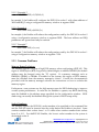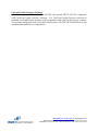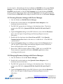
1
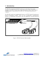
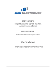
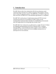
DSP-100
Dual Channel RS-232 PCMCIA
Asynchronous Adapter
for PCMCIA Card Standard compatible machines
User's Manual
INTERFACE CARDS FOR IBM PC/AT AND PS/2
QUATECH, INC.
5675 Hudson Industrial Parkway
Hudson, Ohio 44236
TEL: (330) 655-9000
FAX: (330) 655-9010
www.quatech.com
Warranty Information
Quatech Inc. warrants the
DSP-100
to be free of defects for one (5) year from the date of purchase.
Quatech Inc. will repair or replace any adapter that fails to perform under normal operating conditions
and in accordance with the procedures outlined in this document during the warranty period. Any
damage that results from improper installation, operation, or general misuse voids all warranty rights.
The authors have taken due care in the preparation of this document and any associated software
program(s). In no event will Quatech Inc. be liable for damages of any kind, incidental or consequential,
in regard to or arising out of the performance or form of the materials presented herein and in the
program(s) accompanying this document. No representation is made regarding the suitability of this
product for any particular purpose.
Quatech Inc. reserves the right to edit or append to this document or the product(s) to which it refers at
any time and without notice.
Please complete the following information and retain for your records. Have this information available
when requesting warranty service.
Date of purchase:
Model Number:
DSP-100
Product Description:
Dual Channel Asynchronous RS-232
Communications PCMCIA Adapter
Serial Number:
www.bb-elec.com [email protected] [email protected]
i
International Office: 707 Dayton Road PO Box 1040 Ottawa, IL 61350 USA 815-433-5100 Fax 433-5104
European Office: Westlink Commercial Park Oranmore Co. Galway Ireland +353 91 792444 Fax +353 91 792445
Quatech, Inc.
Declaration of Conformity
Manufacturer's Name:
Quatech, Inc.
Manufacturer's Address:
5675 Hudson Industrial Pkwy.
Hudson, OH 44236 (USA)
Application of Council Directive:
89/336/EEC
Standards to which
Conformity is Declared:
* EN50081-1
(EN55022)
* EN50082-1
(IEC 801-2, IEC 801-3, & IEC 801-4)
Type of Equipment:
Information Technology Equipment
Equipment Class:
Commercial, Residential, & Light
Industrial
Product Name:
PCMCIA Card
Model Number :
DSP-100
www.bb-elec.com [email protected] [email protected]
International Office: 707 Dayton Road PO Box 1040 Ottawa, IL 61350 USA 815-433-5100 Fax 433-5104
DSP-100 (Rev. G and later) User's Manual
ii
European Office: Westlink Commercial Park Oranmore Co. Galway Ireland +353 91 792444 Fax +353 91 792445
Table of Contents
Introduction . . . . . . . . . . . . . . . . . . . . . . . . . . . . . . . . . . . . . . . . . . . . . . . . . . . . . . . . . . 1-1
DOS/Windows 3.x . . . . . . . . . . . . . . . . . . . . . . . . . . . . . . . . . . . . . . . . . . . . . . . . . . . . 2-2
DSP-100 Client Driver for DOS . . . . . . . . . . . . . . . . . . . . . . . . . . . . . . . . . . . . . . . . . 2-3
Client Driver Installation . . . . . . . . . . . . . . . . . . . . . . . . . . . . . . . . . . . . . . . . . . . 2-3
Command Line Options . . . . . . . . . . . . . . . . . . . . . . . . . . . . . . . . . . . . . . . . . . . . 2-4
Common Problems . . . . . . . . . . . . . . . . . . . . . . . . . . . . . . . . . . . . . . . . . . . . . . . . 2-6
DSP-100 Enabler for DOS . . . . . . . . . . . . . . . . . . . . . . . . . . . . . . . . . . . . . . . . . . . . . . 2-7
Command Line Options . . . . . . . . . . . . . . . . . . . . . . . . . . . . . . . . . . . . . . . . . . . . 2-8
Common Problems . . . . . . . . . . . . . . . . . . . . . . . . . . . . . . . . . . . . . . . . . . . . . . . 2-10
Windows 95/98/Millennium (ME) . . . . . . . . . . . . . . . . . . . . . . . . . . . . . . . . . . . . . 3-1
Installing a DSP-100 Under Windows 95/98/ME . . . . . . . . . . . . . . . . . . . . . . . . . . 3-1
DSP-100 Resource Settings in Windows 95/98/ME . . . . . . . . . . . . . . . . . . . . . . . . 3-1
Viewing Resource Settings with Device Manager . . . . . . . . . . . . . . . . . . . . . . . 3-2
Changing Resource Settings with Device Manager . . . . . . . . . . . . . . . . . . . . . . 3-2
Frequently Asked Questions . . . . . . . . . . . . . . . . . . . . . . . . . . . . . . . . . . . . . . . . . . . 3-3
Windows 2000/XP . . . . . . . . . . . . . . . . . . . . . . . . . . . . . . . . . . . . . . . . . . . . . . . . . . . . 4-1
Installing a DSP-100 Under Windows 2000/XP . . . . . . . . . . . . . . . . . . . . . . . . . . . . 4-1
DSP-100 Resource Settings in Windows 2000/XP . . . . . . . . . . . . . . . . . . . . . . . . . . 4-4
Viewing Resource Settings with Device Manager . . . . . . . . . . . . . . . . . . . . . . . 4-6
Changing Resource Settings with Device Manager . . . . . . . . . . . . . . . . . . . . . . 4-7
Windows NT . . . . . . . . . . . . . . . . . . . . . . . . . . . . . . . . . . . . . . . . . . . . . . . . . . . . . . . . . 5-2
Installing DSP-100 . . . . . . . . . . . . . . . . . . . . . . . . . . . . . . . . . . . . . . . . . . . . . . . . . . . . 5-2
External Connections . . . . . . . . . . . . . . . . . . . . . . . . . . . . . . . . . . . . . . . . . . . . . . . . . 6-1
Specifications . . . . . . . . . . . . . . . . . . . . . . . . . . . . . . . . . . . . . . . . . . . . . . . . . . . . . . . . 7-2
www.bb-elec.com [email protected] [email protected]
iii
International Office: 707 Dayton Road PO Box 1040 Ottawa, IL 61350 USA 815-433-5100 Fax 433-5104
European Office: Westlink Commercial Park Oranmore Co. Galway Ireland +353 91 792444 Fax +353 91 792445
Quatech, Inc.
1. Introduction
The DSP-100 is a dual channel RS-232 asynchronous serial adapter for systems
equipped with PCMCIA Type II and/or Type III expansion sockets. The DSP-100 is a
PCMCIA Type II (5 mm) card and is PCMCIA PC Card Standard Specification 2.1
compliant.
The DSP-100's serial port is implemented using two 16C750 Universal Asynchronous
Receiver/Transmitters (UARTs), which are the recommended communications
interface for multitasking environments and with applications involving high data
transfer rates.
PCMCIA Card
Cable Assembly
Standard D-9 Male (2)
Figure 1. DSP-100 Card and Cable Assembly
www.bb-elec.com [email protected] [email protected]
Introduction
International Office: 707 Dayton Road PO Box 1040 Ottawa, IL 61350 USA 815-433-5100 Fax 433-5104
European Office: Westlink Commercial Park Oranmore Co. Galway Ireland +353 91 792444 Fax +353 91 792445
1-1
This page intentionally left blank.
2-1
www.bb-elec.com [email protected] [email protected]
DSP-100
User’s Manual
International Office: 707 Dayton Road PO(Rev.
Box 1040G
Ottawa,
61350 USA 815-433-5100 Fax 433-5104
andIL later)
European Office: Westlink Commercial Park Oranmore Co. Galway Ireland +353 91 792444 Fax +353 91 792445
2. DOS/Windows 3.x
Note: Quatech PCMCIA DOS support is dependent upon type of machine
and card and socket services software support. DOS support is not
guaranteed.
Two configuration software programs are provided with the DSP-100: a Client Driver,
and a card Enabler. Both of these programs are executed from DOS (before entering
Windows) and allow operation of the DSP-100 in both the DOS and Windows 3.x
environments. For optimal operation, however, the Client Driver is the preferred
method of installation and configuration. The table below highlights the differences
between these programs.
Client Driver (recommended)
File type: DOS device driver
Interfaces to PCMCIA Card
and Socket Services software
(PCMCIA host adapter
independent)
Enabler
File type: DOS executable
Interfaces directly to Intel
82365SL and other PCIC
compatible PCMCIA host
adapters
Allows automatic configuration Does not support automatic
of DSP-100 adapters upon
configuration of adapters upon
insertion (Hot Swapping)
insertion (Hot Swapping)
Requires PCMCIA Card and
Socket Services software
Does not require PCMCIA
Card and Socket Services
software
Figure 2. Client Driver versus Enabler for DOS/Windows 3.x.
Card and Socket Services software is commercially available from several vendors for
most desktop and laptop PCs. If you are unsure whether Card and Socket Services
software is currently installed on your system, install the DSP-100 Client Driver as
discussed in following section. When loaded, the Client Driver will display an error
message if Card and Socket Services software is not detected.
www.bb-elec.com [email protected] [email protected]
DOS/Windows 3.x
International Office: 707 Dayton Road PO Box 1040 Ottawa, IL 61350 USA 815-433-5100 Fax 433-5104
European Office: Westlink Commercial Park Oranmore Co. Galway Ireland +353 91 792444 Fax +353 91 792445
2-2
2.1 DSP-100 Client Driver for DOS
In order to use the DSP-100 Client Driver, the system must be configured with Card
and Socket Services software. Card and Socket Services software is not provided with
the DSP-100 but is available from Quatech.
IMPORTANT:
Some versions of Card and Socket Services dated before
1993 do not support general purpose I/O cards. If after
careful installation of the Client Driver the adapter does
not configure or operate properly, an updated version of
Card and Socket Services may be required.
2.1.1 Client Driver Installation
The following procedure is used to install the DSP-100 Client Driver:
1. Copy the Client Driver from the DSP-100 distribution diskette onto the
system's hard drive.
2. Using an ASCII text editor, open the system's CONFIG.SYS file located in the
root directory of the boot drive.
3. Locate the line(s) in the CONFIG.SYS file where the Card and Socket Services
software is installed.
4. AFTER the line(s) installing the Card and Socket Services software, add the
following line to the CONFIG.SYS file:
DEVICE
=
drive:\path\
DSP130CL.SYS options
where options are the DSP-100 Client Driver
command line options discussed on the following pages.
5. Save the CONFIG.SYS file and exit the text editor.
6. Insert the DSP-100 into one of the system's PCMCIA slots.
NOTE: Since the DSP-100 Client Driver supports "Hot Swapping", it is not
necessary to have the DSP-100 installed when booting the system. By inserting
the card before booting, however, the Client Driver will report the adapter
configuration during the boot process thereby verifying the changes made to the
CONFIG.SYS.
7. Reboot the system and note the message displayed when the DSP-100 Client
Driver is loaded. If the Client Driver reports an "invalid command line
option", correct the entry in the CONFIG.SYS file and reboot the system
again. If the Client Driver reports "Card and Socket Services not found", a
version of Card and Socket Services must be installed on the system or the
www.bb-elec.com [email protected] [email protected]
2-3
International Office: 707 Dayton Road PO Box 1040 Ottawa, IL 61350 USA 815-433-5100 Fax 433-5104
(Rev.
G and
later)
European Office: Westlink Commercial Park Oranmore
Co. Galway
Ireland
+353 91 792444 Fax +353 91 792445
DSP-100
User’s Manual
DSP-100 Enabler program must be used to configure the adapter. If the
Client Driver reports the desired adapter configuration, the installation
process is complete and the DSP-100 may be removed and/ or inserted from
the system as desired. On each insertion into the PCMCIA socket, the
DSP-100 will be automatically reconfigured according to the command line
options.
2.1.2 Command Line Options
The DSP-100 Client Driver accepts up to eight command line arguments from the user
to determine the configuration of theDSP-100. If any arguments are provided, the
Client Driver will attempt to configure any DSP-100s with the options specified in the
order they are entered on the command line. Each argument must be enclosed in
parenthesis and must be separated from other arguments by a space on the command
line. Within each argument, any or all of the following parameters may be specified
using a comma (no spaces) to separate each parameter:
Baddress
specifies a the base I/O address of the DSP-100 in hexadecimal. This
address must reside on an even 8-byte boundary. If this option is omitted, a
base address will be assigned by Card and Socket Services.
Iirq
specifies the interrupt level (IRQ) of the DSP-100 in decimal. irq must be one
of the following values: 3, 4, 5, 7, 9, 10, 11, 12, 14, 15, or 0 if no IRQ is
desired. If this option is omitted, an interrupt level will be assigned by Card
and Socket Services.
Ssocket
specifies which PCMCIA socket the DSP-100 must be inserted into for this
configuration argument to be used. socket must be in the range 0 - 15. If this
option is omitted, the configuration argument will apply to DSP-100s
inserted into any socket.
Cclock
specifies the multiple of the standard frequency for the UART clock. Valid
values for clock are 1 or 8. A value of 1 yields a clock frequency of 1.8432
MHz; a value of 8 yields 14.7456 MHz. If this option is omitted, the
standard clock frequency will be used.
2.1.2.1Example 1
DEVICE = C:\DSP-100\ DSP130CL.SYS
In example 1, no command line arguments are specified. The Client Driver will
configure a DSP-100 inserted into any socket with a base address and IRQ assigned by
Card and Socket Services.
www.bb-elec.com [email protected] [email protected]
DOS/Windows 3.x
International Office: 707 Dayton Road PO Box 1040 Ottawa, IL 61350 USA 815-433-5100 Fax 433-5104
European Office: Westlink Commercial Park Oranmore Co. Galway Ireland +353 91 792444 Fax +353 91 792445
2-4
2.1.2.2 Example 2
DEVICE = C:\DSP-100\DSP130CL.SYS (b290,i11)
In example 2, a single command line argument is provided. The Client Driver will
attempt to configure a DSP-100 inserted into any socket with a base address of 290H
and IRQ 11. If address 290H or IRQ 11 is unavailable, the DSP-100 will not be
configured.
2.1.2.3 Example 3
DEVICE = C:\DSP-100\DSP130CL.SYS(s0,b300,i5,o2)
In example 3, a single command line argument is provided. The Client Driver will
attempt to configure a DSP-100 inserted into socket 0 with a base address of 300H and
IRQ 5. If address 300H or IRQ 5 is unavailable, the DSP-100 will not be configured. In
addition, if aDSP-100 is inserted into any other socket, it will not be configured.
2.1.2.4 Example 4
DEVICE = C:\DSP-100\DSP130CL.SYS(i5,h,b300)
In example 4, a single command line argument is provided. Because the parameter
order is not significant, the Client Driver will attempt to configure a DSP-100 inserted
into any socket with a base address of 300H and IRQ 5. If address 300H or IRQ 5 is
unavailable, the DSP-100 will not be configured.
2.1.2.5 Example 5
DEVICE = C:\DSP-100\DSP130CL.SYS (b300,i5) (i10) ( )
In example 5, three command line arguments are provided. The Client Driver will first
attempt to configure a DSP-100 inserted into any socket with a base address of 300H
and IRQ 5. If address 300H or IRQ 5 is unavailable, the Client Driver will proceed to
the second command line argument and attempt to configure the card with a base
address assigned by Card and Socket Services and IRQ 10. If IRQ 10 is also
unavailable, the Client Driver will proceed to the third command line argument and
attempt to configure the DSP-100 with a base address and an IRQ assigned by Card and
Socket Services.
www.bb-elec.com [email protected] [email protected]
2-5
International Office: 707 Dayton Road PO Box 1040 Ottawa, IL 61350 USA 815-433-5100 Fax 433-5104
(Rev.
G and
later)
European Office: Westlink Commercial Park Oranmore
Co. Galway
Ireland
+353 91 792444 Fax +353 91 792445
DSP-100
User’s Manual
2.1.2.6 Example 6
DEVICE = C:\DSP-100\DSP130CL.SYS (b300,i5) ( ) (i10)
In example 6, the three command line arguments of example 5 have been rearranged.
The Client Driver will first attempt to configure a DSP-100 inserted into any socket with
a base address of 300H and IRQ 5. If address 300H or IRQ 5 is unavailable, the Client
Driver will proceed to the second command line argument and attempt to configure the
card with a base address and IRQ assigned by Card and Socket Services. Since the
second command line argument includes all available address and IRQ resources, the
third command line argument will never be reached by the Client Driver. It is the
user's responsibility to place the command line arguments in a logical order.
2.1.2.7 Example 7
DEVICE = C:\DSP-100\DSP130CL.SYS (s0,b300,i5) (s1,b340,i10)
The type of configuration shown in example 7 may be desirable in systems where more
than one DSP-100 is to be installed. In this example, the Client Driver will attempt to
configure a DSP-100 inserted into socket 0 with a base address of 300H and IRQ 5. If
the DSP-100 is inserted into socket 1, the Client Driver will attempt to configure it with
base address 340H and IRQ 10. This allows the user to force the DSP-100's address and
IRQ settings to be socket specific which may simplify cable connections and software
development. As in the previous examples, however, if the requested address or
interrupt resources are not available, the DSP-100 will not be configured.
2.1.3 Common Problems
Generic Client Drivers:
Many Card and Socket Services packages include a generic client driver (or
SuperClient) which configures standard I/O devices. If one of these generic client
drivers is installed, it may configure the DSP-100 causing the DSP-100 client driver to
fail installation. In these cases, the user should do one of the following:
1. Modify the operation of the generic client driver to disable the configuration
of modem/serial port cards. Consult the Card and Socket Services
documentation for availability and details of this feature.
2. Place the DSP-100 client driver before the generic client driver in the
CONFIG.SYS.
www.bb-elec.com [email protected] [email protected]
DOS/Windows 3.x
International Office: 707 Dayton Road PO Box 1040 Ottawa, IL 61350 USA 815-433-5100 Fax 433-5104
European Office: Westlink Commercial Park Oranmore Co. Galway Ireland +353 91 792444 Fax +353 91 792445
2-6
Available Resources:
One function of the Card and Socket Services software is to track which system
resources (memory addresses, I/O addresses, IRQs, etc.) are available for assignment to
inserted PCMCIA cards. Sometimes, however, the Card Services software assumes or
incorrectly determines that a particular resource is used when it is actually available.
Most Card and Socket Services generate a resource table in a file (typically in the form
of an .INI file) which the user can modify to adjust the available system resources.
Consult the Card and Socket Services documentation for availability and details of this
feature.
Multiple Configuration Attempts:
Some Card and Socket Services have a setting which aborts the configuration process
after a single configuration failure (such as a request for an unavailable resource). The
user should change this setting to allow for multiple configuration attempts. Consult
the Card and Socket Services documentation for availability and details of this feature.
Older Versions of Card and Socket Services:
Some versions of Card and Socket Services dated before 1993 do not support general
purpose I/O cards. If after careful installation of the Client Driver the DSP-100 does
not configure or operate properly, an updated version of Card and Socket Services may
be required. Card and Socket Services software is available from Quatech.
2.2 DSP-100 Enabler for DOS
For systems that are not operating PCMCIA Card and Socket Services software, the
DSP-100 DOS Enabler may be used to enable and configure the adapter. This Enabler,
SSP200EN.EXE, will operate on any DOS system using an Intel 82365SL or PCIC
compatible PCMCIA host adapter including the Cirrus Logic CL-PD6710 /6720, the
VLSI VL82C146, and the Vadem VG-365 among others.
IMPORTANT:
In order to use the DSP-100 Enabler for DOS, the system
MUST NOT be configured with Card and Socket Services
software. If a Card and Socket Services software is installed,
the DSP-100 Enabler may interfere with its operation and
with the device(s) it controls.
www.bb-elec.com [email protected] [email protected]
2-7
International Office: 707 Dayton Road PO Box 1040 Ottawa, IL 61350 USA 815-433-5100 Fax 433-5104
(Rev.
G and
later)
European Office: Westlink Commercial Park Oranmore
Co. Galway
Ireland
+353 91 792444 Fax +353 91 792445
DSP-100
User’s Manual
The DSP-100 Enabler does not support automatic configuration of adapters upon
insertion, more commonly referred to as "Hot Swapping". This means the adapter must
be installed in one of the system's PCMCIA sockets before executing DSP130EN.EXE. If
more than one adapter is installed in a system, the Enabler must be executed separately
for each adapter. Furthermore, DSP130EN.EXE should be executed to release the
resources used by the adapter before it is removed from the PCMCIA socket. Since
PCMCIA adapters do not retain their configuration after removal, any adapter that is
removed from the system must be reconfigured with the Enabler after re-inserting it
into a PCMCIA socket.
IMPORTANT:
The Enabler requires a region of high DOS memory when
configuring a DSP-100. This region is 1000H bytes (4KB) long
and by default begins at address D0000H (the default address
may be changed using the "W" option). If a memory manager
such as EMM386, QEMM, or 386Max is installed on the system,
this region of DOS memory must be excluded from the memory
manager's control. Consult the documentation provided with
the memory manager software for instructions on how to
exclude this memory region.
2.2.1 Command Line Options
To configure a DSP-100 in the system, the Enabler requires one command line
argument from the user to determine the configuration of the card. This argument
must be enclosed in parenthesis and within the argument, any or all of the following
parameters may be specified using a comma (no spaces) to separate each parameter:
Ssocket
specifies which PCMCIA socket the DSP-100 must be inserted into for this
configuration argument to be used. socket must be in the range 0 - 15. This
option is required if the 'R' option is not used.
Baddress
specifies the base I/O address of the DSP-100 in hexadecimal. This address
must reside on an even 8-byte boundary. This option is required if the 'R'
option is not used.
Iirq
specifies the interrupt level (IRQ) of the DSP-100 in decimal. irq must be one
of the following values: 3, 4, 5, 7, 9, 10, 11, 12, 14, 15, or 0 if no IRQ is
desired. This option is required if the 'R' option is not used.
www.bb-elec.com [email protected] [email protected]
DOS/Windows 3.x
International Office: 707 Dayton Road PO Box 1040 Ottawa, IL 61350 USA 815-433-5100 Fax 433-5104
European Office: Westlink Commercial Park Oranmore Co. Galway Ireland +353 91 792444 Fax +353 91 792445
2-8
Waddress specifies the base address of the memory window required to configure the
DSP-100. Set address = D0 for a memory window at segment D000, address =
D8 for a memory window at segment D800, etc. Valid settings for address
are C8, CC, D0, D4, D8, and DC. If this option is omitted, a memory
window at segment D000 will be used.
Cclock
specifies the multiple of the standard frequency for the UART clock. Valid
values for clock are 1 or 8. A value of 1 yields a clock frequency of 1.8432
MHz; a value of 8 yields 14.7456 MHz. If this option is omitted, the
standard clock frequency will be used.
Before removing a DSP-100 from its PCMCIA socket, the Enabler should be executed to
free the system resources allocated when the card was installed. For this operation the
Enabler provides on additional command line option:
R
instructs the enabler to release the resources previously allocated to the
DSP-100. When the 'R' option is used, any settings specified by the 'B' and 'I'
options are ignored.
2.2.1.1 Example 1
DSP130EN.EXE
In example 1, no command line argument is specified. The Enabler will report an error
and display the proper usage of the command.
2.2.1.2 Example 2
DSP130EN.EXE (s0,b300,i5)
In example 2, the Enabler will configure the DSP-100 in socket 0 with a base address of
300H and IRQ 5 using a configuration memory window at segment D000.
2.2.1.3 Example 3
DSP130EN.EXE (i10,h,b340,s1)
In example 3, the Enabler will configure the DSP-100 in socket 1 with a base address of
340H and IRQ 10 using a configuration memory window at segment D000.
2.2.1.4 Example 4
DSP130EN.EXE (s0,b300,i3,wd8)
In example 4, the Enabler will configure the DSP-100 in socket 0 with a base address of
300H and IRQ 3 using a configuration memory window at segment D800.
www.bb-elec.com [email protected] [email protected]
2-9
International Office: 707 Dayton Road PO Box 1040 Ottawa, IL 61350 USA 815-433-5100 Fax 433-5104
(Rev.
G and
later)
European Office: Westlink Commercial Park Oranmore
Co. Galway
Ireland
+353 91 792444 Fax +353 91 792445
DSP-100
User’s Manual
2.2.1.5 Example 5
DSP130EN.EXE (o1,i5,b340,s1)
In example 2, the Enabler will configure the DSP-100 in socket 1 with a base address of
340H and IRQ 5 using a configuration memory window at segment D000.
2.2.1.6 Example 6
DSP130EN.EXE (s0,b300,i5,r)
In example 6, the Enabler will release the configuration used by the DSP-100 in socket 0
using a configuration memory window at segment D000. The base address and IRQ
parameters are ignored and may be omitted.
2.2.1.7 Example 7
DSP130EN.EXE (s1,r,wcc)
In example 7, the Enabler will release the configuration used by the DSP-100 in socket 1
using a configuration memory window at segment CC00.
2.2.2 Common Problems
Memory Range Exclusion:
The Enabler requires a region of high DOS memory when configuring a DSP-100. This
region is 1000H bytes (4KB) long and by default begins at address D0000H (the default
address may be changed using the "W" option). If a memory manager such as
EMM386, QEMM, or 386Max is installed on the system, this region of DOS memory
must be excluded from the memory manager's control. Consult the documentation
provided with the memory manager software for instructions on how to exclude this
memory region.
Furthermore, some systems use the high memory area for BIOS shadowing to improve
overall system performance. In order for the Enabler to operate, any BIOS shadowing
must be disabled in the address range specified for the configuration window. BIOS
shadowing can usually be disabled through the system's CMOS setup utility.
Socket Numbers:
The Enabler requires the DSP-100's socket number to be specified on the command line
and the DSP-100 must be inserted into the socket before the Enabler is invoked. Some
vendors number their sockets from 1 to N while other vendors number their sockets
from 0 to N-1. For theDSP-100 Enabler, the lowest socket number in the system is
designated socket 0.
www.bb-elec.com [email protected] [email protected]
DOS/Windows 3.x
International Office: 707 Dayton Road PO Box 1040 Ottawa, IL 61350 USA 815-433-5100 Fax 433-5104
European Office: Westlink Commercial Park Oranmore Co. Galway Ireland +353 91 792444 Fax +353 91 792445
2-10
Card and Socket Services Software:
In order to use the DSP-100 Enabler for DOS, the system MUST NOT be configured
with Card and Socket Services software. If a Card and Socket Services software is
installed, the Enabler may interfere with its operation and with the device(s) it controls.
For systems configured with Card and Socket Services, the DSP-100 Client Driver is the
recommended method of configuration.
www.bb-elec.com [email protected] [email protected]
2-11
International Office: 707 Dayton Road PO Box 1040 Ottawa, IL 61350 USA 815-433-5100 Fax 433-5104
(Rev.
G and
later)
European Office: Westlink Commercial Park Oranmore
Co. Galway
Ireland
+353 91 792444 Fax +353 91 792445
DSP-100
User’s Manual
3. Windows 95/98/Millennium (ME)
To allow easy configuration of
the DSP-100, a Windows 95/98/ME "INF"
configuration file has been written for the hardware.
3.1 Installing a DSP-100 Under Windows 95/98/ME
1. Insert the DSP-100 into any available PC Card socket.
2. The first time a new PC Card type is installed the New Hardware Found
window opens. After this first installation Windows 95/98/ME will
automatically detect and configure the card. If the New Hardware Found
window does not open, then skip to the next section, “DSP-100 Resource
Settings".
3. The New Hardware Found window provides several options to configure
the DSP-100 card. Click the "Search for the best driver for your device"
option button. Click "NEXT" to continue.
4. An "Install from Disk" dialog box should appear. Insert the Quatech COM
CD file, select the correct drive letter and path, and click "OK". Windows
95/98/ME will browse the path for the aforementioned files.
5. During the installation process, it may be required to supply the computer
with the Windows 95/98/ME CD or installation CDs. Insert the CD and
click "OK".
The DSP-100 PC Card should now be configured. With the default configuration,
the DSP-100's interrupt status register will be enable and the 16C750 UART’s
scratchpad register will be disabled. In the future, Windows 95/98/ME will
automatically recognize and configure the DSP-100 in this default configuration.
3.2 DSP-100 Resource Settings in Windows 95/98/ME
Windows 95/98/ME maintains a registry of all known hardware installed within the
computer. Inside this hardware registry Windows 95/98/ME keeps track of all the
computer's resources, such as base I/O addresses, IRQ levels, and DMA channels. In
the case of a PC Card (PCMCIA) type board, Windows 95/98/ME configures the new
hardware using free resources it finds within the hardware registry, and updates the
registry automatically.
www.bb-elec.com [email protected] [email protected]
International Office: 707 Dayton Road PO Box 1040 Ottawa, IL 61350 USA 815-433-5100 Fax 433-5104
Windows 95/98/Millennium (ME)
3-1
European Office: Westlink Commercial Park Oranmore Co. Galway Ireland +353 91 792444 Fax +353 91 792445
To view and/or edit hardware devices in Windows 95/98/ME use the system Device
Manager. To access Device Manager double click the System icon in the Windows
95/98/ME control panel, or click the My Computer icon on the Windows 95/98/ME
desktop with the right mouse button and select Properties from the pull down menu.
Consult Windows 95/98/ME on-line help for details on the use of the Device Manager.
3.2.1Viewing Resource Settings with Device Manager
1. Start the Windows 95/98/ME Device Manager.
2. Double click on the hardware class Quatech Comm Adapters to list
hardware devices in the class.
3. The DSP-100 “parent device” belongs to this hardware class. The device
name for the DSP-100 is Quatech DSP-100: Dual RS-232 Serial Port PC
Card.
4. Open the Properties dialog for the DSP-100 device, then click the Resources
tab to view the Input/Output Range and Interrupt Request resource
allocations.
5. Double click the hardware class Ports (Com and LPT). Each Quatech
Communications Port listed in this class is a “child device” of the DSP-100
“parent device.”
6. Open the Properties dialog for a COM port, then click the Resources tab to
view the Input/Output Range and Interrupt Request resource allocations.
These will match those of the “parent device.”
7. Record the COM Port device names (COM1, COM2, etc.) for the DSP-100.
These names are required by Windows 95/98/ME applications when
accessing particular ports.
3.2.2Changing Resource Settings with Device Manager
1. Start the Windows 95/98/ME Device Manager.
2. Double click on the hardware class Quatech Comm Adapters to list
hardware devices in the class.
3. The DSP-100 “parent device” belongs to this hardware class. The device
name for the DSP-100 is Quatech DSP-100: Dual RS-232 Serial Port PC
Card.
4. Open the Properties dialog for the DSP-100 device, then click the Resources
tab to view the Input/Output Range and Interrupt Request resource
allocations.
www.bb-elec.com [email protected] [email protected]
3-2
International Office: 707 Dayton Road PO Box 1040 Ottawa, IL 61350 USA 815-433-5100 Fax 433-5104
(Rev.
G and
later)
European Office: Westlink Commercial Park Oranmore
Co. Galway
Ireland
+353 91 792444 Fax +353 91 792445
DSP-100
User’s Manual
5. Several predefined Basic Configurations have been included for the DSP-100
(see Figure 5. DSP-100 Basic Configuration Table). The Basic Configurations
provide many combinations of the operating modes and options listed below.
See the Hardware Information section of this manual for complete
descriptions.
When the Use Automatic Settings check box is enabled Windows 95/98/ME
will attempt to configure the DSP-100 in the order listed in the Basic
Configurations table.
Basic
Configuration
0000
0001
0002
0003
I/O Range***
Any
Any
Any
Any
Clock
Speed
Normal
8x
Normal
8x
Scratch
Pad/ ISR
ISR
ISR
Scratch Pad
Scratch Pad
*** Any indicates variable value; this value may or may not be user selectable depending on
platform.
6. Select a Basic Configurations that displays "No conflicts" in the bottom
display region titled Conflicting Device List from the drop down list.
7. To modify the Interrupt Request setting click the resource name and click
the Change Setting button. An Edit Resource window will open up. Inside
this window click on the up/down arrows to the right of the Interrupt
Request value. This scrolls you through all of the allowable resources for
your hardware. Pay attention to the conflict information at the bottom of the
window. Do not select a value that causes a conflict with any other installed
hardware.
8. If any changes have been made to the DSP-100’s configuration the card will
automatically be reconfigured to the new resources specified. Any time a
PCMCIA card of this type is inserted Windows 95/98/ME will attempt to
configure the card at these resource settings. Click the Use Automatic
Settings box to reset this card type for automatic configuration.
3.3 Frequently Asked Questions
Basic Configuration List Not Available:
A problem noted on some systems is after a basic configuration has been manually
selected the basic configurations list for the DSP-100 is no longer available. The
solution to this problem is to check the “Use Automatic Settings” box and allow
Windows 95/98/ME to reconfigure the DSP-100 card. The basic configurations list
should once again be visible.
www.bb-elec.com [email protected] [email protected]
International Office: 707 Dayton Road PO Box 1040 Ottawa, IL 61350 USA 815-433-5100 Fax 433-5104
Windows 95/98/Millennium (ME)
3-3
European Office: Westlink Commercial Park Oranmore Co. Galway Ireland +353 91 792444 Fax +353 91 792445
Base I/O Address Resource Modification Not Allowed:
The DSP-100 is configured to allow only a fixed number of base I/O addresses. To
change the I/O address resources for the DSP-100 select another “Basic Configuration”.
Refer to the Basic Configurations table for a list of the availabe I/O address resources
for the DSP-100.
www.bb-elec.com [email protected] [email protected]
3-4
International Office: 707 Dayton Road PO Box 1040 Ottawa, IL 61350 USA 815-433-5100 Fax 433-5104
(Rev.
G and
later)
European Office: Westlink Commercial Park Oranmore
Co. Galway
Ireland
+353 91 792444 Fax +353 91 792445
DSP-100
User’s Manual
4 Windows 2000/XP
To allow easy configuration of the DSP-100, a Windows 2000/XP "INF" configuration
file has been written for the hardware.
4.1 Installing a DSP-100 Under Windows 2000/XP.
1. Insert the Quatech COM CD into an available CD-ROM.
2. Insert the DSP-100 into any available PC Card socket.
3. You will be prompted to search for the correct driver. Choose the drive
where the Quatech COM CD is located and select “Browse” from the ‘Files
Needed’window.
www.bb-elec.com [email protected] [email protected]
Windows 2000/XP
International Office: 707 Dayton Road PO Box 1040 Ottawa, IL 61350 USA 815-433-5100 Fax 433-5104
European Office: Westlink Commercial Park Oranmore Co. Galway Ireland +353 91 792444 Fax +353 91 792445
4-1
4. Double click ‘Serial Port Adapters’
5. Double click ‘Drivers’
www.bb-elec.com [email protected] [email protected]
4-2
International Office: 707 Dayton Road PO Box 1040 Ottawa, IL 61350 USA 815-433-5100 Fax 433-5104
(Rev.
G and
later)
European Office: Westlink Commercial Park Oranmore
Co. Galway
Ireland
+353 91 792444 Fax +353 91 792445
DSP-100
User’s Manual
6. Double click on ‘Windows 2000, XP, for PCI, PCMCIA, ISA’
7. Click on ‘qserbrd’and select open
www.bb-elec.com [email protected] [email protected]
Windows 2000/XP
International Office: 707 Dayton Road PO Box 1040 Ottawa, IL 61350 USA 815-433-5100 Fax 433-5104
European Office: Westlink Commercial Park Oranmore Co. Galway Ireland +353 91 792444 Fax +353 91 792445
4-3
8. Select ‘OK’at the ‘Files Needed’window\
9. The same process as above in steps 1-9 will apply for the next file ‘qserpt.inf’.
In step 7 be sure to choose ‘qserpt.inf’and select ‘Open’.
4.2 DSP-100 Resource Settings in Windows 2000/XP
Windows 2000/XP maintains a registry of all known hardware installed within the
computer. Inside this hardware registry Windows 2000/XP keeps track of all the
computer's resources, such as base I/O addresses, IRQ levels, and DMA channels. In
the case of a PC Card (PCMCIA) type board, Windows 2000/XP configures the new
hardware using free resources it finds within the hardware registry, and updates the
registry automatically.
To view and/or edit hardware devices in Windows 2000/XP use the system Device
Manager.
To access Device Manager double click the System icon in the Windows 2000/XP control panel, or
click the My Computer icon on the Windows 2000/XP desktop with the right mouse button and select
Properties from the pull down menu. Click on the Hardware tab then click on the Device Manager.
Consult Windows 2000/XP on-line help for details on the use of the Device Manager
www.bb-elec.com [email protected] [email protected]
4-4
International Office: 707 Dayton Road PO Box 1040 Ottawa, IL 61350 USA 815-433-5100 Fax 433-5104
(Rev.
G and
later)
European Office: Westlink Commercial Park Oranmore
Co. Galway
Ireland
+353 91 792444 Fax +353 91 792445
DSP-100
User’s Manual
Windows 2000/XP handles the DSP-100 as a "parent/child device".
v The DSP-100 is the "parent device" and is listed under the hardware class
Quatech Multiport Serial Devices in the device manager.
v Each serial port is a "child device" of the "parent device" DSP-100 (Quatech
PCMCIA Serial Port). There are 2 child COM ports for the DSP-100 (Quatech
PCMCIA Serial Port) which are listed under the hardware class Ports (Com &
LPT).
www.bb-elec.com [email protected] [email protected]
Windows 2000/XP
International Office: 707 Dayton Road PO Box 1040 Ottawa, IL 61350 USA 815-433-5100 Fax 433-5104
European Office: Westlink Commercial Park Oranmore Co. Galway Ireland +353 91 792444 Fax +353 91 792445
4-5
4.2.1 Viewing Resource Settings with Device Manager
1. Start the Windows 2000/XP Device Manager.
2. Double click on the hardware class Quatech Multiport Serial Devices to list
hardware devices in the class.
3. The DSP-100 “parent device” belongs to this hardware class. The device
name for the DSP-100 is Quatech DSP-100 PCMCIA Two-Port RS-232 Serial
Adapter.
4. Open the Properties dialog for the DSP-100 device, then click the Resources
tab to view the Input/Output Range and Interrupt Request resource
allocations. Examine and remember the Input/Output Range, then close the
properties window.
5. Double click the hardware class Ports (Com and LPT). The Quatech
PCMCIA Serial Port listed in this class is the “child device” of the DSP-100
“parent device.”
www.bb-elec.com [email protected] [email protected]
4-6
International Office: 707 Dayton Road PO Box 1040 Ottawa, IL 61350 USA 815-433-5100 Fax 433-5104
(Rev.
G and
later)
European Office: Westlink Commercial Park Oranmore
Co. Galway
Ireland
+353 91 792444 Fax +353 91 792445
DSP-100
User’s Manual
6. Use the COM Port device names (COM5, COM6, etc.) to access any of the
particular serial ports on the DSP-100. This name is required by a Windows
2000 application when accessing a particular port.
4.2.2 Changing Resource Settings with Device Manager
1. Start the Windows 2000/XP Device Manager.
2. Double click on the hardware class Quatech Multiport Serial Devices to list
hardware devices in the class.
3. The DSP-100 “parent device” belongs to this hardware class. The device
name for the DSP-100 is Quatech DSP-100 PCMCIA Two-Port RS-232 Serial
Adapter.
4. Open the Properties dialog for the DSP-100 device,then click the Advanced
tab to view the clock rate settings.
www.bb-elec.com [email protected] [email protected]
Windows 2000/XP
International Office: 707 Dayton Road PO Box 1040 Ottawa, IL 61350 USA 815-433-5100 Fax 433-5104
European Office: Westlink Commercial Park Oranmore Co. Galway Ireland +353 91 792444 Fax +353 91 792445
4-7
www.bb-elec.com [email protected] [email protected]
4-8
International Office: 707 Dayton Road PO Box 1040 Ottawa, IL 61350 USA 815-433-5100 Fax 433-5104
(Rev.
G and
later)
European Office: Westlink Commercial Park Oranmore
Co. Galway
Ireland
+353 91 792444 Fax +353 91 792445
DSP-100
User’s Manual
Clock Mode
Auto
X1
X2
X4
X8
Data Rate Multiplier
Max bps
Description
Auto clock mode enables applications to request
any baud rate up to 921,600. The hardware
921,600
drivers will select the correct clock multiplier
based on the baud rate requested
The X1 clock mode mimics a standard COM port.
The hardware drivers lock the clock to the
115,200
standard rate. The port will run at the baud rate
requested by the application.
The X2 clock mode locks the ports hardware
clock at double the standard rate. The baud rate
the port runs at will always be double the rate
230,400
requested by the applications. This mode is
useful for legacy applicattions which cannot
request baud rates over 115,200
The X4 clock mode locks the ports hardware clock
at four times the standard rate. The baud rate the
port runs at will always be four times the rate
460,800
requested by the application. This mode is useful
for legacy applications which cannot request
baud rates over 115.200.
The X8 clock mode locks the ports hardware clock
at eight times the standard rate. The baud rate
the port runs at will always be eight times the
921,600
rate requested by the application. This mode is
useful for legacy applications which cannot
request baud rates over 115.200.
5. Open the Properties dialog for the DSP-100 device, then click the Resources
tab to view the Input/Output Range and Interrupt Request resource
allocations. If options that are not available on the preceding pages are
required, a different basic configuration will have to be selected. To do this,
de-select the Use Automatic Settings box and choose the basic configuration
that corresponds to the set of options required.
www.bb-elec.com [email protected] [email protected]
Windows 2000/XP
International Office: 707 Dayton Road PO Box 1040 Ottawa, IL 61350 USA 815-433-5100 Fax 433-5104
European Office: Westlink Commercial Park Oranmore Co. Galway Ireland +353 91 792444 Fax +353 91 792445
4-9
Basic
Configuration
I/O Range
IRQ
0000
0001
0002
0003
0004
Variable
2E0-2EF
3E0-3EF
2F0-2FF
3F0-3FF
Variable
Variable
Variable
Variable
Variable
Basic
Configuratio
n
0000
0001
0002
0003
0004
6. Select a Basic Configurations that displays "No conflicts" in the bottom
display region titled Conflicting Device List from the drop down list.
www.bb-elec.com [email protected] [email protected]
4-10
International Office: 707 Dayton Road PO Box 1040 Ottawa, IL 61350 USA 815-433-5100 Fax 433-5104
(Rev.
G and
later)
European Office: Westlink Commercial Park Oranmore
Co. Galway
Ireland
+353 91 792444 Fax +353 91 792445
DSP-100
User’s Manual
7. Windows 2000/XP should have chosen an available Interrupt Request
setting automatically when the I/O address range was configured by a Basic
Configuration selection. This default Interrupt Request setting should not
need changed as long as "No conflicts" is displayed in the bottom display
region titled Conflicting Device List. If you are satisfied with Windows
2000/XP selection then skip the next step
8. To modify the Interrupt Request setting click the resource name and click
the Change Setting button. An Edit Resource window will open up. Inside
this window click on the up/down arrows to the right of the Interrupt
Request value. This scrolls you through all of the allowable resources for
your hardware. Pay attention to the conflict information at the bottom of the
window. Do not select a value that causes a conflict with any other installed
hardware.
9. If any changes have been made to the DSP-100’s configuration the card will
automatically be reconfigured to the new resources specified. Any time a
PCMCIA card of this type is inserted Windows 2000/XP will attempt to
configure the card at these resource settings. Click the Use Automatic
Settings box to reset this card type for automatic configuration.
www.bb-elec.com [email protected] [email protected]
Windows 2000/XP
International Office: 707 Dayton Road PO Box 1040 Ottawa, IL 61350 USA 815-433-5100 Fax 433-5104
European Office: Westlink Commercial Park Oranmore Co. Galway Ireland +353 91 792444 Fax +353 91 792445
4-11
This page intentionally left blank.
www.bb-elec.com [email protected] [email protected]
5-1
International Office: 707 Dayton Road PO Box 1040 Ottawa, IL 61350 USA 815-433-5100 Fax 433-5104
(Rev.
G and
later)
European Office: Westlink Commercial Park Oranmore
Co. Galway
Ireland
+353 91 792444 Fax +353 91 792445
DSP-100
User’s Manual
5 Windows NT
5.1 Installing DSP-100
To allow easy configuration of the DSP-100 the Quatech Device Manager for Windows
NT has been written for the hardware. This configuration utility supports the DSP-100
only in block addressing mode.
To begin the installation, open Windows Explorer and search for the ‘Setup.exe’
command to install the Quatech Device Manager. <See following Windows Explorer
figure.> (D:\Serial Port Adapters\Drivers\Windows NT 4.0 for PCI, PCMCIA,ISA).
Once the installation is complete an icon will be placed on the desktop.
Windows NT Explorer
www.bb-elec.com [email protected] [email protected]
Windows NT
International Office: 707 Dayton Road PO Box 1040 Ottawa, IL 61350 USA 815-433-5100 Fax 433-5104
European Office: Westlink Commercial Park Oranmore Co. Galway Ireland +353 91 792444 Fax +353 91 792445
5-2
1. Locate and double click the Quatech Device Manager icon on the desktop
Device Manager Icon on Desktop
www.bb-elec.com [email protected] [email protected]
5-3
International Office: 707 Dayton Road PO Box 1040 Ottawa, IL 61350 USA 815-433-5100 Fax 433-5104
(Rev.
G and
later)
European Office: Westlink Commercial Park Oranmore
Co. Galway
Ireland
+353 91 792444 Fax +353 91 792445
DSP-100
User’s Manual
2. Click the ‘Add’button at the bottom of the Quatech Device Manager Window
3. Follow the steps for the ‘Add Quatech Hardware Wizard’.
www.bb-elec.com [email protected] [email protected]
Windows NT
International Office: 707 Dayton Road PO Box 1040 Ottawa, IL 61350 USA 815-433-5100 Fax 433-5104
European Office: Westlink Commercial Park Oranmore Co. Galway Ireland +353 91 792444 Fax +353 91 792445
5-4
4. Complete the final steps of the installation, shut down Windows NT insert
the PCMCIA Card and re-boot the computer.
Additional help is available online
The DSP-100 PC Card should now be configured. In the future, Windows NT will
automatically recognize and configure the DSP-100.
Note: Windows NT does not support ‘Plug and Play’for PCMCIA cards. The
PCMCIA Card must be inserted prior to starting Windows NT and can not be removed
and reinserted while Windows NT is running.
www.bb-elec.com [email protected] [email protected]
5-5
International Office: 707 Dayton Road PO Box 1040 Ottawa, IL 61350 USA 815-433-5100 Fax 433-5104
(Rev.
G and
later)
European Office: Westlink Commercial Park Oranmore
Co. Galway
Ireland
+353 91 792444 Fax +353 91 792445
DSP-100
User’s Manual
6. External Connections
An adapter cable is included with the DSP-100 to convert the 9-pin PCMCIA output
connector into a standard D-9 male connector, data terminal equipment (DTE), as
shown in the figures below.
Standard D-9
(Male)
Figure 14. DSP-100 Adapter Cable.
GND
5
DTR
4
TxD
3
RxD
2
DCD
1
9
RI
8
CTS
7
RTS
6
DSR
D-9 Male Connector
Figure 15. RS-232 Signal Assignment.
www.bb-elec.com [email protected] [email protected]
External Connections
International Office: 707 Dayton Road PO Box 1040 Ottawa, IL 61350 USA 815-433-5100 Fax 433-5104
European Office: Westlink Commercial Park Oranmore Co. Galway Ireland +353 91 792444 Fax +353 91 792445
6-1
This page intentionally left blank.
www.bb-elec.com [email protected] [email protected]
7-1
International Office: 707 Dayton Road PO Box 1040 Ottawa, IL 61350 USA 815-433-5100 Fax 433-5104
(Rev.
G and
later)
European Office: Westlink Commercial Park Oranmore
Co. Galway
Ireland
+353 91 792444 Fax +353 91 792445
DSP-100
User’s Manual
7. Specifications
Bus Interface
PCMCIA
PC Card Standard 2.1 compliant
Physical Dimensions
Type II PCMCIA card (5mm)
Maximum Baud Rate
921.6K
Power Requirements
+5 volts
Connector
Adapter to two standard male
D-9
30 mA (typical)
45 mA (maximum)
www.bb-elec.com [email protected] [email protected]
Specifications
International Office: 707 Dayton Road PO Box 1040 Ottawa, IL 61350 USA 815-433-5100 Fax 433-5104
European Office: Westlink Commercial Park Oranmore Co. Galway Ireland +353 91 792444 Fax +353 91 792445
7-2
DSP-100
User's Manual
Revision 3.20
February 2005
P/N 940-0088-320
www.bb-elec.com [email protected] [email protected]
Quatech, Inc.
International Office: 707 Dayton Road PO Box 1040 Ottawa, IL 61350 USA 815-433-5100 Fax 433-5104
European Office: Westlink Commercial Park Oranmore Co. Galway Ireland +353 91 792444 Fax +353 91 792445