1
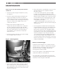
This manual must be kept with the appliance
August 2012
Part No. E281
MAXXflo
Installation guide, operation
and maintenance manual
High Efficiency Condensing
Stainless Steel Storage
Water Heaters for
Natural Gas and Propane
Natural Gas Models
CWH30/200, CWH30/300
CWH60/200, CWH60/300
CWH90/200, CWH90/300
CWH120/200, CWH120/300
Propane Models
LCWH30/200, LCWH30/300
LCWH60/200, LCWH60/300
LCWH90/200, LCWH90/300
LCWH120/200, LCWH120/300
Working towards
a cleaner future
2
SECTION XX • XXXXXXXXX
Reproduction of any information in this publication by any method is not permitted
unless prior written approval has been obtained from Andrews Water Heaters.
Andrews Storage Water Heaters have been designed and manufactured to comply
with current international standards of safety. In the interests of the health and safety
of personnel and the continued safe, reliable operation of the equipment, safe working
practices must be employed at all times. The attention of UK users is drawn to their
responsibilities under the Health and Safety Regulations 1993.
All installation and service on Andrews Water Heaters must be carried out by properly
qualified personnel and, therefore, no liability can be accepted for any damage or
malfunction caused as a result of intervention by unauthorised personnel.
Andrews Water Heaters’ policy is one of continuous product improvement and,
therefore, the information in this manual, whilst completely up to date at the time of
publication, may be subject to revision without prior notice.
Further information and assistance can be obtained from:
Andrews Water Heaters
Wood Lane, Erdington,
Birmingham B24 9QP
Tel: 0845 070 1055
Fax: 0845 070 1059
Email: [email protected]
Website: www.andrewswaterheaters.com
THE ANDREWS WATER HEATERS COVERED IN THIS MANUAL
ARE FOR USE WITH NATURAL GAS OR LPG (PROPANE) GAS ONLY
Copyright Andrews Water Heaters 2010
XXXXXXXXX • SECTION
XX
CONTENTS
3
PAGE
SECTION 1
SECTION 2
SECTION 3
SECTION 4
SECTION 5
SECTION 6
SECTION 7
SECTION 8
GENERAL AND SAFETY INFORMATION
General Information
British Standards and Codes of Practice
Health and Safety Regulations 1993
Legionellae in Water Heaters
4
4
4
5
TECHNICAL DETAILS
Technical Details – CWH30/60/90/120
Heater Dimensions – 200 litre model
Heater Dimensions – 300 litre model
6
7
8
INSTALLATION
Description
Location
Water Quality and Treatment
Water Connections
Condense Drain
Typical Installations – CWH30/60 & CWH90/120
Gas Supply – Natural Gas
Gas Supply – Propane
Typical Bulk Storage Vessel Installation
Typical Cylinder Installation
Electrical Supply
Electrical Connection
Wiring Diagram
Temporary Water Heater Temperature Change
Circulation Pump and Storage Tanks
HWST Tank Dimensions and Wiring Diagram
Flue Systems
Flue Systems – CWH 30 & 60
Alternative Flue Systems – CWH 30 & 60
Standard Flue System Dimensions – CWH 30 & 60
Flue Systems – CWH 90 & 120
Alternative Flue Systems – CWH 90 & 120
Standard Flue System Dimensions – CWH 90 & 120
Flue System Positions and Distances
Flue System – Horizontal and Vertical Terminations
Air Supply and Ventilation – Concentric Flue Systems
Air Supply and Ventilation – Concentric and Conventional Flue Systems
Air Supply and Ventilation – Conventional Flue Systems
Heat Exchanger Configuration
Control Panel
9
9
10
10
11
12
13
13
14
14
15
15
16
17
17
18
19
20
21
22
23
24
25
26
27
28
29
30
31
31
WATER TEMPERATURE SETTINGS
Temperature Setting
Adjusting Temporary Temperature Change
32
32
INSTRUCTIONS FOR COMMISSIONING
Filling the Water Heater
Commissioning – Natural Gas and Propane
CO2 Adjustment
Control and Adjustment at Full Load
Control and Adjustment at Low Load
Decommissioning
Draining the Water Heater
33
33
33
34
34
34
34
FAULT CODES
Fault Codes
Blocking Faults
Lockout Faults
35
35
35
MAINTENANCE
Annual Maintenance Checks
36
PARTS LIST
Spares List for CWH Range
Unvented System Kits
37
39
4
XX• •GENERAL
XXXXXXXXX
SECTION 1
AND SAFETY INFORMATION
GENERAL AND SAFETY INFORMATION
The Andrews Water Heater has been designed for use
with NATURAL GAS OR LPG and is manufactured to give
an efficient, reliable and long service life.
To ensure the continued, trouble-free operation of your
heater at maximum efficiency, it is essential that correct
installation, commissioning, operation and service
procedures are carried out strictly in accordance with the
instructions given in this manual. By law, installation and
commissioning of the heater must be carried out by
properly qualified personnel.
The heater(s) must be installed in accordance with the
following requirements:
The current GAS SAFETY (INSTALLATION AND USE)
REGULATIONS
I/M2
Purging procedures for non-domestic gas
installations.
I/M5
Soundness testing procedures for
industrial and commercial gas
installations.
I/M11
Flues for commercial and industrial gas
fired boilers and air heaters.
I/M16
Notes on installation of gas pipework
(excluding 25mm and below).
LPGA Code of practice 7:
Storage of full and empty LPG cylinders
and cartridges. Highly Flammable Liquids
and Liquid Petroleum Gases Regulations
1972.
The current BUILDING REGULATIONS
The WATER SUPPLY (WATER FITTINGS)
REGULATIONS 1999
Additionally, installation should be performed in
accordance with all relevant requirements of the Gas
Supplier, Local Authority and recommendations of the
British Standards and Codes of Practice detailed below.
BRITISH STANDARDS AND CODES
OF PRACTICE
BS 6700: 1997 Specification for design, installation,
testing and maintenance of services supplying water for
domestic use within buildings and their curtilages. This
standard supersedes the following British Standards and
Codes of Practice: CP99, CP310, CP324, 202, CP342
Part 2, Centralised Hot Water Supply.
BS 5440:1990 Installation of flues and ventilation for gas
appliances of rated output not exceeding
60kW.
Part 1
Specification for installation of flues.
Part 2
Specification for installation of ventilation
for gas appliances.
BS 5546:1990 Installation of gas hot water supplies for
domestic purposes.
BS 6891
Installation of low pressure gas pipework
of up to 28mm in domestic premises.
BS 6644
Installation of gas fired water boilers of
rated inputs between 60kW and 2mW
BS 7206:1990 Specification for unvented hot water
storage units and packages.
IGE/UP/10 Part 1 Edition 2:
Installation of Gas Appliances in Industrial
and Commercial Premises.
Terms:
a. Andrews Water Heaters accepts no liability for any
damage resulting from failing to accurately follow the
instructions.
b. When replacing parts during maintenance, only original
parts from Andrews Water Heaters should be used;
these can be recognised by the name of the
manufacturer printed on them.
HEALTH AND SAFETY REGULATIONS
1993
It is the duty of manufacturers and suppliers of products
for use at work to ensure, so far as is practicable, that
such products are safe and without risk to health when
properly used, and to make available to users adequate
information about their safe and proper operation.
Andrews Water Heaters should only be used in the
manner and purpose for which they are intended and in
accordance with the instructions in this manual. Although
the heaters have been manufactured with paramount
consideration to safety, certain basic safety precautions
highlighted in this manual must be observed by the user.
It is imperative that all users of the heaters must be
provided with all the information and instruction necessary
to ensure correct and safe operation.
XXXXXXXXX • •SECTION
XX
GENERAL AND SAFETY INFORMATION
SECTION
1
EFFECTIVENESS IN COMBATING
LEGIONELLA
Water systems in buildings have been associated with
outbreaks of Legionnaires’ Disease, particularly in health
care facilities where occupants are significantly more
susceptible to infection.
In recognition of the risks in hospitals, a Code of Practice
for the Control of Legionella in Health Care premises has
been issued by the Department of Health (1991). Codes
of Practice applicable to other premises have been
published by other organisations, principally the Health
and Safety Executive (HS)(G70) and the Chartered
Institute of Building Services Engineers (CIBSE, TM13).
All Codes of Practice draw attention to the design and
operation of water systems with reference to avoidance of
factors that favour colonisation by Legionella bacteria.
These factors include stagnation, lukewarm conditions
(20°C to 45°C) and the accumulation of debris, scale and
corrosion in the base of tanks and calorifiers.
The MAXXflo range has a Legionella flushing programme
– see page 15 – BTI – BT2
5
6
SECTION 2
XX • • TECHNICAL
XXXXXXXXXDETAILS
Model Reference CWH
Input gross Hs min/max
Input nett Hi min/max
Output (tank set point = 60°C) min/max
30/200
30/300
6.7–31.1 kW
6.0–28.0 kW
6.5–30.5 kW
60/200
60/300
13.4–62.2 kW
12.0–56.0 kW
13.0–61.0 kW
90/200
90/300
20.1–93.3 kW
18.0-84.0 kW
19.5-91.6 kW
120/200
120/300
26.8-124.4 kW
24.0-112.0 kW
26.0-122.1 kW
2.96 m3/h
18 mbar
5.93 m3/h
18 mbar
8.89 m3/h
18 mbar
11.85 m3/h
18 mbar
2.18 Kg/h
37 mbar
98%
109%
4.35 Kg/h
37 mbar
98%
109%
780 Mj per month
25ppm
44mg/kWh
51dBA
6.0µA
4.0µA
1.0 – 1.4 kΩ
960 l/h
856 l/h
6.53 Kg/h
37 mbar
98%
109%
8.71 Kg/h
37 mbar
98%
109%
25ppm
44mg/kWh
51dBA
6.0µA
4.0µA
1.0 – 1.4 kΩ
1440 l/h
1284 l/h
25ppm
44mg/kWh
51dBA
6.0µA
4.0µA
1.0 – 1.4 kΩ
1920 l/h
1712 l/h
13 mins
19 mins
80/125
80
12
20
140 Pa
1½” BSP
1” BSP
3.5 bar
6.0 bar
1.0 bar
3
⁄4”
All models: 230/50V/Hz
340 W
170 kg
180 kg
370 kg
480 kg
193 kg
203 kg
1040 mm
880 mm
1653 mm
2077 mm
9 mins
13 mins
130/200
130
14
50
140 Pa
1½” BSP
1” BSP
3.5 bar
6.0 bar
1.0 bar
3
⁄4”
7 mins
10 mins
130/200
130
14
40
140 Pa
1½” BSP
1” BSP
3.5 bar
6.0 bar
1.0 bar
3
⁄4”
510 W
185 kg
195 kg
385 kg
495 kg
208 kg
218 kg
1040 mm
880 mm
1653 mm
2077 mm
680 W
200 kg
210 kg
400 kg
513 kg
213 kg
233 kg
1040 mm
880 mm
1653 mm
2077 mm
Natural Gas, G20
Gas Consumption
Minimum Dynamic Gas Supply Pressure
Propane, G31
Gas Consumption
Minimum Dynamic Gas Supply Pressure
Efficiency (gross)
Efficiency (nett)
Standby Heat Loss
NOx level @ 0% O2
NOx level @ 0% O2
Noise level ✽
Ionisation current – max
Ionisation current – min
HSI resistance
Max recovery thru 50°C
Max recovery thru 56°C
Time to recover tank thru 50°C rise
200 litre capacity
300 litre capacity
Flue size (concentric) Internal/External
Flue Size (conventional)
Max flue run – concentric ✽✽
Max flue run – conventional ✽✽✽
Max flue static pressure
Inlet/Outlet connections
Return connection
Nominal operating water pressure
Maximum water pressure
Minimum water pressure
Gas connection (gas cock supplied)
Electrical supply
Power consumption
Weight – empty (200 litre)
Weight – empty (300 litre)
Weight – full (200 litre)
Weight – full (300 litre)
Shipping weight (200 litre)
Shipping weight (300 litre)
Shipping depth
Shipping width
Shipping height (200 litre)
Shipping height (300 litre)
25ppm
44mg/kWh
51dBA
6.0µA
4.0µA
1.0 – 1.4 kΩ
480 l/h
429 l/h
25 mins
38 mins
80/125
80
14
50
140 Pa
1½” BSP
1” BSP
3.5 bar
6.0 bar
1.0 bar
3
⁄4”
170 W
155 kg
165 kg
355 kg
465 kg
178 kg
188 kg
1040 mm
880 mm
1653 mm
2077 mm
Noise level measured at 2m from flue terminal
Reduce flue length by 1.2m for 90° bend, 0.7m for 45° bend and 1.5m for condensate trap
✽✽✽ Reduce flue length by 4m for 90° bend, 2m for 45° bend and 4m for condensate trap
✽
✽✽
The MAXXflo range features stainless steel tanks with external heat exchanger(s) and fully automatic electronic control with
BEMS interface as standard. The heaters must be installed with a minimum water pressure of 1 bar. The heaters are factory
fitted with temperature and pressure relief valve(s). A gas cock, water draw-off cock and comprehensive instruction manual
are also included. The water heaters can be fitted with concentric flue for room sealed applications; horizontal or vertical flue
kits must be ordered separately – see pages 20 and 23.
Conventional flue, suitable for condensing applications can be used if the plantroom is ventilated.
TECHNICAL
DETAILS • • SECTION
SECTIONXX
2
XXXXXXXXX
INSPECTION HATCH
INSPECTION HATCH
7
8
XX • • TECHNICAL
XXXXXXXXXDETAILS
SECTION 2
INSPECTION HATCH
INSPECTION HATCH
XXXXXXXXX
TECHNICAL
DETAILS • • SECTION
SECTIONXX
2
9
INSTALLATION
DESCRIPTION
The MAXXflo series is a direct fired condensing storage
water heater which has a stainless steel tank that is
heated by up to four burner modules placed outside the
tank. A burner module consists of a stainless steel heat
exchanger in which the burner is placed.
The water heater works according to the loading
principle: The water in the bottom of the tanks is led
directly through the heat exchanger, heated up and
carried back to the top of the tank. The temperature of
the water at the bottom of the tank (return temperature) is
representative of the input heat; the burner modulates on
the basis of this return temperature. The temperature at
which the water is supplied to the tank from the heat
exchanger (supply temperature) is kept at the set water
heater temperature using pump modulation.
An important advantage of bringing the heat transfer from
outside the tank is that the output is not influenced by the
temperatures that prevail in the tank. As long as draw off
occurs, the water from the bottom of the tank to the heat
exchanger is almost the same as the supply cold water
temperature. This means the maximum output is
maintained during the heating up period. On the final
heating period, when the tank is almost completely
heated up, the return temperature will increase and the
burner modulates. Because the water is pumped round
from the lowest point in the tank, the whole tank is heated
up and there are no cool zones.
The water heater is equipped with a maximum of four
burner modules dependent on the model. Each burner
module produces a maximum of 30.5 kW output for a set
water heater temperature of 60°C.
Important Note:
• Minimum water pressure = 1 bar
• Mains feed only
THE LAW REQUIRES THAT THE INSTALLATION
IS CARRIED OUT BY A PROPERLY QUALIFIED
PERSON
Installations must be carried out in accordance with Gas
Safety (Installation and Use) Regulations 1998, Building
Regulations, The Water Supply (Water Fittings)
Regulations 1999 and any requirements of the local Gas
Authority, Local Authority, Water and Fire Authorities and
the current British Standards and Codes of Practice listed
in Section 1.
The location selected for installation of the heater must
allow the provision of a satisfactory flue, adequate air
supply, drain facilities and must be well illuminated.
A purpose built water heater room or compartment is
strongly recommended.
A manual valve for isolation of the water heater room
should be installed in the gas supply. It should be clearly
identified and readily accessible for use at all times.
If a purpose built water heater room is not available,
measures should be taken to protect the heater from
damage and prevent any extraneous matter from being
stored on or around the heater. See BS6644 Clauses 4, 5
and 6 for details.
The heater must not be installed in any location which
contains a bed, bath or shower. There must be easy
access to the water heater room and heater at all times.
The water heater must be located in an area where
leakage from the tank, water connections or the
combination temperature and safety valve will not result in
damage to the area adjacent to the water heater. When
such locations cannot be avoided, a suitable drain tray
must be installed under the water heater. The drain tray
must be no deeper than 38mm and must be 100mm
wider and longer than the heater. The drain tray must be
piped to an adequate drain using 20mm (0.75in) diameter
pipe, angled for proper drainage.
Access must be provided to the front of the water heater
and adequate clearance for its servicing and operation.
The floor on which the heater is installed must be flat,
level and of sufficient strength to withstand the weight of
the heater when filled with water, and should satisfy the
requirements of the Local Authority & Building
Regulations.
Any combustible material adjacent to the heater must be
so placed and shielded as to ensure that its temperature
does not exceed 66°C (150°F).
Place the water heater on a flat floor in a frost-proof area.
See pages 5, 6 and 7 for recommended service
clearances.
10
XX • • INSTALLATION
XXXXXXXXX
SECTION 3
WATER QUALITY AND TREATMENT
When installing Andrews Water Heaters in hard water
areas we would recommend that a water treatment
specialist is consulted.
In hard water areas, scale formation can occur in all hot
water systems and water heaters and the higher the
temperature and volume of water used, the more
problematic the scale build-up can be. Water treatment
is normally recommended when the hardness reaches
100 – 150ppm (7 – 10 degrees Clark) and above. This
problem can be minimised by reducing the water
temperature in the heater and by fitting suitable water
pre-treatment equipment. It is for this reason we strongly
recommend water pre-treatment is fitted. A baseexchange type of softener is strongly recommended
for a reliable solution to hard water.
WATER CONNECTIONS
An unvented system must be fitted by an
approved installer.
The pressure reducing valve C1 will regulate the mains
water pressure at 3.5 bar (provided there is sufficient
mains water pressure available). The maximum test
pressure should be 8 bar. The expansion vessel C3
supplied is suitable for the stored volume of the heater
Fig 1
Expansion Vessel
and a comparative pipe work system. The temperature
and pressure relief valve(s) are factory fitted. FOR
SYSTEMS WITH LARGER PIPE VOLUMES OR
ADDITIONAL STORAGE, EXPANSION VESSELS
WITH MORE CAPACITY ARE AVAILABLE.
We do not recommend the use of galvanised pipework
due to issues such as galvanic attack (British Standard
BS6644). The MAXXflo has a number of copper and
brass components.
The cold water connection and the hot water connection
can be found on the top of the appliance, see Fig 1A and
1B. An extra connection is available for the benefit of a
circulation line. Please note that a stop valve should be
fitted in the circulation line.
The MAXXflo range of storage water heaters are designed
to work from a mains fed unvented system. An unvented
kit to regulate the cold feed is supplied with each heater
and should be installed as Fig. 1, 1a and 1b plus
drawings on pages 5, 6 and 7.
The temperature and pressure relief valves are supplied
factory fitted for external connection to a tundish
(supplied) and suitable drain. The MAXXflo can also
operate on vented systems providing the minimum water
pressure is one bar.
XXXXXXXXX • • SECTION
INSTALLATION
SECTIONXX
3
11
SECONDARY RETURN
CIRCULATION PUMP
CONDENSE DRAIN
Condensation is formed in the heater and this must be
continuously discharged into a drain. A trap is supplied
which should be connected into a drain via a tundish or
air break. (See Fig 1a and 1b). The condense flow must
not be allowed to block otherwise the heater will fail to
work correctly. NOTE: AN AIR BREAK IS REQUIRED
DOWNSTREAM OF THE TRAP TO PROTECT THE
WATER HEATER FROM BLOCKAGES AND
SUBSEQUENT DAMAGE. Each 30kW module could
produce up to 3 litres of condense per hour while at
full load.
An additional connection for a secondary circulation is
available in the top of the heater that is located between
the hot flow and cold feed ports. We would recommend
that a non-return valve is fitted in the return line.
If a secondary return circuit is fitted with a secondary
pump, please ensure that the flow-rate does not exceed
the heater maximum flow-rate. An excessive flow in the
secondary circuit could result in a temperature mixing
effect in the heater storage vessel resulting in a stored
water temperature less than the set temperature (see
table below).
Model Type CWH30
Maximum
0.9
flow rate m3/h
CWH60
1.8
CWH90 CWH120
2.7
3.6
Fig 2
Circulation Pump
Secondary
Return Line
Cold Water
12
SECTION 3
XX • • INSTALLATION
XXXXXXXXX
Fig 3A – Typical installation
Fig 3B – Typical installation
INSTALLATION
SECTIONXX
3
XXXXXXXXX • • SECTION
13
GAS SUPPLY – NATURAL GAS
GAS SUPPLY – PROPANE
The installation of the gas supply must conform,
depending on its size, to the requirements of British
Standards and Codes of Practice listed in Section 1 of
this manual.
Contact your provider or supplier who will provide the
appropriate type and size of LPG supply vessel and
ensure its safe location and installation.
A gas meter will be connected to the service pipe by
British Gas plc or its authorised contractor.
The installation of the gas supply must confirm to LGPA
Code of Practice, 22 LPG Piping Systems: Design and
Installation plus the requirements of British Standards and
Codes of Practice listed in Section 1 of this manual.
The meter and service pipe should be checked by British
Gas or its authorised contractor to ensure that they are
adequate to deal with the gas supply to the water
heater(s) in addition to any existing or additional
requirements.
Andrews Water Heaters are unregulated and a second
stage regulator must be installed to give an inlet pressure
to the appliance as follows: (see fig 2)
PROPANE
Fit the service gas cock (supplied) to the gas connection
on top of the water heater using a suitable jointing
compound and connect to the gas supply.
Where the water heater(s) is(are) installed in a water
heater house or purpose built compartments, a manually
operated valve for the water heater house must be fitted
in accordance with the Gas Safety (Installation and Use)
Regulations 1998. The valve must be easily identified and
readily accessible.
After installation, the system should be pressure tested for
soundness and purged in accordance with BS6891 or
IM/2 and IM/5 as appropriate.
Please note that the minimum dynamic gas pressure for
Natural Gas must not fall below 18 mbar.
37 mbar (14.86 in wg)
When using propane cylinders, connect a minimum of
47kg cylinders as listed below, together with a manifold
before connecting to the union.
Use a minimum pipe size of ¾" bore.
Two 47kg Cylinders
Three 47kg Cylinders
Four 47kg Cylinders
LCWH30 and LCWH60
LCWH90
LCWH120
WARNING!
PROPANE CYLINDERS MUST BE USED AND
STORED IN ACCORDANCE WITH ‘THE HIGHLY
FLAMMABLE LIQUIDS AND LIQUIFIED
PETROLEUM GASES REGULATIONS 1972’ AND
SHOULD COMPLY WITH LPGA CODE OF PRACTICE
7: ‘STORAGE OF FULL AND EMPTY LPG
CYLINDERS AND CARTRIDGES’.
Also please note that for Propane the minimum dynamic
gas pressure to the unit must not fall below 37 mbar.
14
XX • • INSTALLATION
XXXXXXXXX
SECTION 3
Fig 4: Typical Bulk Storage Vessel Installation
Fig 5: Typical Cylinder Installation
Important
These drawings show a schematic representation only and should not be used for installation purposes.
Contact your gas supplier for authorised installation drawings.
XXXXXXXXX • • SECTION
INSTALLATION
SECTIONXX
3
15
ELECTRICAL SUPPLY
ELECTRICAL CONNECTION
External wiring to the water heater(s) must be installed in
accordance with current I.E.E. Regulations for the wiring
of buildings and to any Local Regulations that may apply.
A terminal block can be found above the control panel
(Fig 4, below). This becomes accessible by first removing
the front cover.
The MAXXflo range is designed to operate from a
permanent 230v/50Hz single phases sup The fuse rating
is 5 amps.
The following connections can be made on the terminal
block (see Fig. 5 – Wiring diagram, on next page)
Terminals
AL1 – AL2
Maximum Electrical Loading
Model Type
30 kW
60 kW
90 kW
120 kW
Watts
170
340
510
680
EN1 – EN2
Amps
0.74
1.48
2.22
2.96
BT1 – BT2
LS1 – LS2
TH1 – TH2
Pump L – Pump N
The method of connection to the mains electricity supply
should facilitate complete electrical isolation of the
appliance, preferably by use of a fused double pole
switch or fused spur box serving only the heater. The
disconnection of the supply shall have a contact
separation of 3mm on all poles.
*To activate, place a contact across the terminals
The point of connection to the mains electricity supply
should be readily accessible and adjacent to the
appliance.
Fig 6 – Terminal block connections
gy
AL1
br
wh
gn
AL2
gy
r
bl
bk
TH1
br
wh
br
or
TH2
gy
r
y
BT1
br
wh
bl
bl
r
BT2
gy
r
br
br
y
LS1
br
wh
bk
LS2
gy
r
bl
bl
r
TS1
br
br
bk
TS2
r/bl
TS3
br
br
bl
bl
bk
TS4
bl
bl
br
br
gy
EN1
bk
EN2
SECONDARY PUMP
Terminal Function
Alarm volt-free contacts (24 volt 1
amp max.)
Enable or disable contacts volt-free
(link fitted to enable)*
Secondary set point temp. enable
(40 – 75°C)*
Secondary return temp. sensor for
pasteurisation function
Secondary pump control enable*
Secondary pump power supply
(0.7 amp max)
bl
M5910 G
br
M5879D
bk
r
gy
r/bl
y
br
br bl
br
br bl g/y
L N E
230V/50Hz
master
bl
br
gy
r
wh
r
wh
r
gr
br
gr
br
gr
bk
wh
br
bk
r
gr
bk
gy
r/bl
r
bk
y
r
or
y
bk
gn
gy
bl
pump
}
TH1
gr
or
EN1
EN2
TS4
TS3
TS2
LS2
TS1
LS1
BT2
BT1
TH2
r
tank sensor, high position
tank sensor, low position
y
gy
flow sensor 1
or
flow sensor 2
return sensor
br bl
AL1
(Max 24 V 1.0 Amp)
AL2
pump N
secondary
pump
comm. 1
comm. 2
comm. 3
comm. 4
mains 1
mains 2
mains 3
mains 4
pump L
wh
br
br
bl
br
bl
br
bl
br
bl
br
bl
br
bl
br
bl
br
bl
br
bl
br
pi
TS3-TS4 = Tank sensor, high position
EN1-EN2 = enable / disable
or = orange
pi = pink
g/y = green & yellow
bk = black
wh = white
r = red
TS1-TS2 = Tank sensor, low position
gy = grey
BT1-BT2 = Activate Second Setpoint
LS1-LS2 = Secondary Sensor
gn = green
y = yellow
r
AL1-AL2 = Alarm
r
bl
TH1-TH2 = Activate Secondary Pump
bl
br
y
bl
br
bl = blue
bk
slave 1
or
br = brown
wh
bl
gn
y
gy
br
bk
wh
bl
glow plug
primary
pump
gasvalve
ionisation rod
fan
16
XX • • INSTALLATION
XXXXXXXXX
SECTION 3
Fig. 7 – Wiring Diagram
Make sure that the phase (L) and the neutral (N) are connected to the correct terminals on the connector.
The appliance is phase sensitive therefore swapping the phase and neutral will lead to a fault in the appliance.
XXXXXXXXX • • SECTION
INSTALLATION
SECTIONXX
3
TEMPORARY WATER HEATER
TEMPERATURE CHANGE
It is possible to change the water heater temperature
remotely via a timer programme. First of all, the new
desired water heater temperature is set at a value higher
or lower than the water heater temperature during normal
operation. This makes it possible, for example, to carry
out Legionella flushing. (See page 32).
The water heater temperature changes when the
contacts connected to terminals BT1 – BT2 are closed.
The water heater temperature goes back to normal
operation when these contacts are opened again.
If the temperature change is used for Legionella flushing,
it is possible to return the water heater temperature to
normal operation before the timer programme finishes.
This happens on the basis of a temperature
measurement, for example at the end of a circulation line
(secondary return). For this purpose, a 10K NTC
temperature sensor (part number E674) must be
connected to the terminals LS1 – LS2. The water heater
temperature now goes back to normal operation if the
temperature is higher at the measuring point than the
secondary pre-set water heater temperature minus 5°C
FIG 8 – SCHEMATIC SYSTEM DESIGN
17
for 20 minutes. If, for example, the secondary pre-set
water heater temperature is set at 70°C, the water heater
temperature returns back to normal operation as soon as
the temperature at the secondary measuring point has
been above 65°C for more than 20 minutes.
CIRCULATION PUMP AND STORAGE
TANKS
A circulation pump (maximum 0.7 A) can be connected at
the terminal pump L – pump N. The circulation pump can
then be controlled by a thermostat connected to
terminals TH1-TH2. Connecting the contacts of the
thermostat then activates the circulation pump.
The application can be used when the water heater is
combined with a separate storage tank.
As soon as the temperature in the tank gets too low, the
thermostat will activate the pump so the tank is heated up
again. Matching MAXXflo storage tanks are available in
200 and 300 litre sizes, models HWST200 and
HWST300. These tanks are fitted with a thermostat for
use as above. See below for schematic system design
and pages 16 & 18 for tank dimensions and wiring
diagram.
18
SECTION 3
XX • • INSTALLATION
XXXXXXXXX
Fig 9 – HWST Tank Dimensions
HWST 200 HWST 300 STORAGE TANKS
47
T&P outlets
153
Drain access
28 mm valve
153
602
602
PLAN VIEW
1 1/2" Hot
water
supply
Tank inspection hatch
1" Return
28 mm T&P outlets
1 1/2" Feed from
water heater
1 or 2 Tundishes supplied
Fig 10 – Wiring Diagram
1952 (300 litre t ank)
1528 (200 litre t ank)
Thermostat
INSTALLATION
SECTIONXX
3
XXXXXXXXX • • SECTION
19
FLUE SYSTEMS
The versatile flueing options will provide a solution to most
flushing requirements. The heater, when fitted with
a concentric flue system, provides a room sealed
application. The concentric flue, supplied by Andrews,
is available for either horizontal or vertical installation and
the table below shows the basic kit supplied plus optional
extras. Alternatively, the heater can be fitted with a
conventional flue system, which can be obtained from
a specialist flue stockist. A flue system suitable for a
condensing pressurised system must be specified.
The table and the concentric flue component below show
the maximum allowable length of flue for both systems.
The following pages show standard kits and additional
items for concentric flue supplied by Andrews. Horizontal
and vertical flue kits must be ordered separately. Flue kits
are not included in the heater price.
GENERAL
Flue terminals must be installed in accordance with the
Clean Air Act to ensure the products of combustion are
properly dispersed. The drawing shows some minimum
Model
Flue size (concentric)
Max. flue run – concentric (a)
Max. flue run – conventional (b)
Max. flue static pressure
Max. flue gas volume
Max. flue gas temperature
mm
m
m
Pa
m3/h
°C
CWH30
80/125
14
50
140
41
52
clearances for the flue terminal; in addition, the flue
terminal should be positioned where it will not cause a
nuisance from noise or from the combustion products
accumulating. Please contact Andrews technical
department if advice is needed for a particular installation.
See drawings on page 26.
We recommend that a condensate trap be fitted when
the secondary flue length is over 1.5m.
If installed in a roof valley, the terminal should be at least
1m above the highest part of the roof structure and 2.5m
from any adjacent structure. The terminal must be fitted
with a guard if less than 2m above ground level or in a
position where it may cause injury to persons resulting
from touching a hot surface. Guards can be ordered with
flue components. See table on pages 20 and 23.
WARNING!
The flue system must be properly installed.
Ensure the inner flue is securely sealed at all the
joints otherwise incomplete combustion may result.
Do not exceed maximum flue lengths including
elbows.
CWH60
80/125
12
20
140
82
52
CWH90
130/200
14
50
140
123
52
CWH120
130/200
14
40
140
164
52
(a) For a concentric flue/room sealed, reduce flue length by 1.2m for 90° bend, 0.7m for 45° bend and 1.5m
for condense trap.
(b) For a conventional flue, reduce flue length by 4m for 90° bend, 2m for 45° bend and 4 m for condense trap.
The different ventilation requirements for room sealed or conventional flue systems are given on pages 28 – 30.
20
XX • • INSTALLATION
XXXXXXXXX
SECTION 3
CWH30 & CWH60 Flue Systems
The CWH30 & CWH60 uses a concentric flue system, 125mm outside diameter with an inner flue of 80mm diameter.
Flue components fit together with silicon sealing rings and the flues are retained with sealing clamps. Each heater can be
ordered with either a horizontal or vertical flue kit. Flue assembly instructions are also included.
B260 – Horizontal flue kits include the following:
B261 – Vertical flue kits include the following:
A1 – 90° bend with sealing clamp (Part No. E071)
A1 – Roof outlet terminal with sealing clamp. (Part No. E067)
Roof flashing plates and additional Flue components
are available.
A2 – Wall outlet terminal with sealing clamp
complete with inner and outer wall plates
fixing screws and plugs. (Part No. E073)
A1
A2
Can be cut
to suit roof
Standard Length Cut
to suit wall thickness
Wall Pl at es
Sealing Clamps
258
A1
Sealing Clamp
Wall
300
Wall
M inimum
Service Clearance
Hori zont al Ki t
A l t ernati ve Fl ue Syst ems
300
A2
Wall Plates
Standard Length Cut
t o suit wall thickness
V ert i cal Ki t
Optional flue components available
Seal i ng Clamps
A1
With this application
pipes must clear
Horizontal Flue
Wall
100
M inimum
Service
Clearance
Hori zont al Ki t
M inimum
Service Clearance
Add standard or
Add standard
cutable
flue to
or cutable
flue to improve
improve
access
to tank
toaccess
tank top
for
top for inspection
inspection
(See
(see page 35)
page 36
Part No
E071
E308
E064
E070
E069
E065
E066
E068
E105
E310
B260
B261
E211
E075
Description
90° elbow c/w clamp
45° elbow c/w clamp
1m length of flue c/w clamp
1m length cutable flue c/w clamp
0.5m flue c/w clamp
Flat roof plate (125mm)
Angled roof plate (125mm)
Wall clamp (125mm)
Guard for horizontal flue terminal
Flue condense trap
Horizontal flue terminal
Vertical flue terminal
Condensate trap bottle
Flue clamp 125mm
XXXXXXXXX • • SECTION
INSTALLATION
SECTIONXX
3
21
CWH30 & CWH60 Alternative Flue Systems
1.5M
CWH30 max 50M Conventional
CWH60 max 20M Conventional
CWH30 max 14M Concentric
CWH60 max 12M Concentric
Over 1.5M use flue
Condense trap.
258
135
Minimum between
Vertical terminals
Condense Tap
To
drain
300mm
Minimum between balanced
flued horizontal terminals
Paint:
RAL 7012
820
For concentric flue runs
reduce overall length by:
1.2M when using 90º bend
0.7M when using 45º bend
and 1.5M when using
condensetrap
530
Flat roof Flashing
E065
Angled roof
flashing
E066
Can be cut
to suit roof
structure
CWH30 max
50M Conventional
CWH60 max
20M Conventional
805
CWH30 max
14M Concentric
545
CWH60 max
12M Concentric
Can be cut to suit
roof structure
22
XX • • INSTALLATION
XXXXXXXXX
SECTION 3
CWH30 & CWH60 Standard Flue System Dimensions
ALL 80/125mm Ø CONCENTRIC FLUE
570
185
20
290
Ø125
Ø80
Ø 123/124
12
5
CONDENSATE TRAP
Ø
1350
PART No E310
100
150
125
Ø125
0
10
Ø80
45º ELBOW C/W CLAMP
200
20
PART No E308
Ø80
VERTICAL FLUE TERMI NAL
C/W CLAMP (CONDENSING)
PART No E067
200
90º ELBOW C/W CLAMP
PART No E071
220
610
220
Ø80
170
20
200 Min
ADJUSTABLE PLATE
Maintain dimension if
flue is cut
HORIZONTAL TERMINAL C/W WALL PLATES
PART No E073
XXXXXXXXX • • SECTION
INSTALLATION
SECTIONXX
3
23
CWH90 & CWH120 Flue Systems
The CWH90 & CWH120 uses a concentric flue system, 200mm outside diameter with an inner flue of 130mm diameter.
Flue components fit together with silicon sealing rings and the flues are retained with sealing clamps.
Each heater can be ordered with either a horizontal or vertical flue kit. Flue assembly instructions are also included.
B262 – Horizontal flue kits include the following:
B263 – Vertical flue kits include the following:
A1 – 90° bend with sealing clamp (Part No. E215)
A1 – Roof outlet terminal with sealing clamp. (Part No. E670)
Roof flashing plates and additional Flue components
are available.
A2 – Wall outlet terminal with sealing clamp
complete with inner and outer wall plates
fixing screws and plugs. (Part No. E240)
A1
A2
Can be cut
to suit roof
Standard Length Cut
to suit wall thickness
Wall Pl at es
Sealing Clamps
258
A1
Sealing Clamp
Wall
300
Wall
M inimum
Service Clearance
Hori zont al Ki t
A l ternati ve Fl ue Syst ems
300
A2
Wall Plates
Standard Length Cut
t o suit wall thickness
V ert i cal Ki t
M inimum
Service Clearance
Seal i ng Clamps
Optional flue components available
A1
With this application
pipes must clear
Horizontal Flue
Wall
100
M inimum
Service
Clearance
Hori zont al Ki t
Add standard or
Add standard
cutable
flue to
or cutable
flue to improve
improve
access
access
to tank
to
tank top
for
top for inspection
inspection
(See
(see page 35)
page 36
Part No
E215
E216
E212
E213
E214
E217
E218
E219
E630
E220
B263
B262
E211
E385
Description
90° elbow c/w clamp
45° elbow c/w clamp
1m length of flue c/w clamp
1m length cutable flue c/w clamp
0.5m flue c/w clamp
Flat roof plate (200mm)
Angled roof plate (200mm)
Wall clamp (200mm)
Guard for horizontal flue terminal
Flue condense trap
Vertical flue terminal
Horizontal flue terminall
Condensate trap bottle
Flue clamp 200mm
24
SECTION 3
XX • • INSTALLATION
XXXXXXXXX
CWH30 & CWH60 Alternative Flue Systems
258
Over 1.5M use flue
condensetrap.
1.5M
CWH90 max 50M Conventional
CWH120 max 40M Conventional
CWH90 and CWH120 max 14M Concentric
Minimum clearence
between vertical
balanced flue terminals
Condense Tap
To
drain
For concentric flue runs
reduce overall length by:
1.2M when using 90º bend
0.7M when using 45º bend
1.5M when using condense trap
600mm
Minimum clearence
between balanced
flue horizontal terminals
Flat roof Flashing
E217
CWH90 max
50M Conventional
CWH120 max
40M Conventional
530
Angled roof
flashing
E218
Can be cut
to suit roof
structure
CWH90 max
14M Concentric
CWH120 max
14M Concentric
Can be cut to suit
roof structure
INSTALLATION
SECTIONXX
3
XXXXXXXXX • • SECTION
25
CWH90 & CWH120 Standard Flue System Dimensions
ALL 130/200MM fl CONCENTRIC FLUE
0
13
130
185
20
Painted RAL 7012
fl200
fl130
20
fl130
1780
fl 198/199
fl 198/199
CONDENSATE TRAP
45… ELBOW C/W CLAMP
1300
PART No E220
fl 200
785
PART No E216
220
VERTICAL FLUE TERMINAL
C/W CLAMP PART No E670
220
20
268
fl 40
fl32
20
fl130
fl 198/199
CONDENSATE TRAP
PART NO. E211
90… ELBOW C/W CLAMP
PART No E215
300
300
fl 200
670
fl 130
970
20
200mm Min
Maintain dimension
if flue is cut
ADJUSTABLE PLATE
HORIZONTAL TERMINAL C/W WALL PLATES
PART No E240
26
SECTION 3
XX • • INSTALLATION
XXXXXXXXX
FLUE SYSTEMS
Fig 11
Terminal Positions with Minimum Distance
mm
A
Directly below an opening, air brick, opening window etc.
300
B
Above an opening, air brick, opening window etc
300
C
Horizontal to an opening, air brick, opening window etc.
300
D
Below a gutter or sanitary pipework
E
Below the eaves
200
F
Below a balcony or carport roof
200
G
Above ground, roof or balcony level
300
H
From vertical drain/soil pipework
150
J
From an internal or external corner
300
K
From a surface or boundary facing the terminal
L
Vertically from a terminal on the same wall
M
Horizontally from a terminal on the same wall
75
600
1500
(30 & 60kW)
300
(90 & 120kW)
600
N
From a terminal facing the terminal
1200
P
From an opening in a carport (e.g. door, windows) into the building
1200
Q
Above roof
500
R
From a vertical structure on a roof
500
S
Above flat roof
1000
INSTALLATION
XXXXXXXXX • • SECTION
SECTIONXX
3
Flue Systems
Fig 12
27
28
XX • • INSTALLATION
XXXXXXXXX
SECTION 3
AIR SUPPLY AND VENTILATION
CONCENTRIC FLUE SYSTEMS
The following notes are intended to give guidance:
Where the heater is to be installed in a room, NO VENTS
ARE REQUIRED.
Where the heater is to be installed in a COMPARTMENT,
permanent air vents are required in the COMPARTMENT
at high and low level. These air vents must either
communicate with a room or internal space or be direct
to outside air.
The minimum effective areas of the permanent air vents
required in the compartment are as follows:
Air vents should have negligible resistance and must not
be sited in any apposition where they are likely to be
easily blocked or flooded or in any position adjacent to an
extraction system which is carrying flammable vapour.
Consideration must be given to the position of the high
level ventilation opening. A high level vent must not be
sited within 300mm (1ft), measured vertically, of the flue
terminal.
Grilles and louvres should be so designed that high
velocity air streams do not occur within the space
housing the heater(s).
Air Vents Areas
Position of Air Vents
High Level
Low Level
In a Room or Internal Space
Air from Room or Internal Space
10cm2 per kW Net input
10cm2 per kW Net input
No Requirement for Ventilation
Air Direct from Outside
5cm2 per kW Net input
5cm2 per kW Net input
Note: Both air vents must communicate with the same room or internal space or both must be on the same
wall to outside air.
XXXXXXXXX • • SECTION
INSTALLATION
SECTIONXX
3
29
AIR SUPPLY AND VENTILATION
CONCENTRIC FLUE SYSTEMS
AIR SUPPLY AND VENTILATION
CONVENTIONAL FLUE SYSTEMS
IMPORTANT
For all installations, please refer to the table below for
calculating requirements. Detailed recommendations for
the air supply are given in BS5440, Part 2, and BS6644,
Clause 19.3 and in IGE/UP/10, Pt 1.
1. The effective area requirements specified in the table
are related to the maximum heat input of the heater(s)
and are equivalent to those specified in BS6644.
2. The free area of the grilles should not be less than the
size of the recommended ventilation opening.
3. The supply of air to a space housing the heater(s) by
mechanical means should be:
(a)
Mechanical inlet with natural extraction.
(b)
Mechanical inlet with mechanical extraction.
NB!! NATURAL INLET WITH MECHANICAL
EXTRACTION MUST NOT BE USED
Where a mechanical inlet and mechanical extraction
system is used, the design extraction rate must not
exceed one third of the design inlet rate.
All mechanical ventilation systems must be fitted with
automatic gas shut off safety systems which cut off the
supply of gas to the heater(s) in the event of failure of
either the inlet or extract fans.
The requirements for air supply by mechanical ventilation
are given in BS6644, Clause 19.3 and in IGE/UP/10 Pt 1.
The permanent air vents shall be sited away from the
extract fans. It may be necessary to increase the
ventilation area to compensate for the extractor fan.
The following notes are provided for general
guidance only.
Ventilation shall prevent the heater environment from
exceeding 32°C (90°).
The purpose provided space in which the heater(s) are
installed must have permanent air vents communicating
directly with the outside air, at high and low level. Where
communication with the outside air is possible only by
means of high level air vents, ducting down to floor level
for the lower vents must be used.
For an exposed building, air vents must be fitted on at
least two sides, preferably on all four sides.
Air vents should have negligible resistance and must not
be sited in any position where they are likely to be easily
blocked or flooded, or in any position adjacent to an
extraction system which is carrying flammable vapour.
Grilles or louvres should be so designed that high velocity
air streams do not occur within the space housing the
heater(s).
The grilles should have a total minimum free area for the
water heater(s), in addition to any other requirements, as
follows:
Where the heater is to be installed in a room, the
following permanent ventilation is required:
5cm2 per kW in excess of 7kW for installations up to
54kW net.
For installations exceeding 60kW, the following
permanent ventilation is required:
Low Level (inlet)
540cm2 plus 5cm2 per kilowatt in
excess of 54kW total net input
High Level (outlet) 270cm2 plus 2.5cm2 per kilowatt in
excess of 54kW total net input
Where the heater is to be installed in a
compartment, permanent air vents are required in
the compartment at high and low level. These air
vents must either communicate with a room or
internal space or be direct to outside air.
30
XX • • INSTALLATION
XXXXXXXXX
SECTION 3
AIR SUPPLY AND VENTILATION
CONVENTIONAL FLUE SYSTEMS
The minimum effective areas of the permanent air vents
require in the compartment are as follows:
Air Vents Areas
Position of Air Vents
High Level
Low Level
Air from Room or Internal Space
10cm2 per kW Net input
20cm2 per kW Net input
Air Direct from Outside
5cm2 per kW Net input
10cm2 per kW Net input
Note: Both air vents must communicate with the same room or internal space or must both be on the same wall
to outside air.
IMPORTANT!
1. The effective area requirements specified in the table
are related to the maximum heat input of the heater(s)
and are equivalent to those specified in BS6644 and
IGE/UP/10, Pt 1.
2. The free area of the grilles should not be less than the
size of the recommended ventilation opening.
3. The supply of air to a space housing the heater(s) by
mechanical means should be:
(a) Mechanical inlet with natural extraction
(b) Mechanical inlet with mechanical extraction
NOTE! Natural inlet with mechanical extraction
must not be used.
Where a mechanical inlet and mechanical extraction
system is used, the design extraction rate must not
exceed one third of the design inlet rate.
All mechanical ventilation systems must be fitted with
automatic gas shut off safety systems which cut off the
supply of gas to the heater(s) in the event of failure of
either the inlet or extract fans.
The requirements for air supply by mechanical ventilation
are given in BS6644, Clause 19.3 & IGE/UP/10 Pt 1.
The permanent air vents shall be sited away from any
extract fans. Where an extract fan is fitted, check for
spillage at the draught diverter as detailed in BS5440,
Pt 1, Appendix B.
It may be necessary to increase the ventilation are to
compensate for the extract fan.
The vapours emitted by halogen based compounds can,
if drawn into the combustion air, cause corrosion of the
gas burner, thermocouple and storage vessel. Therefore,
if heaters are to be installed in locations where halogens
are likely to be present, they should be isolated from such
compounds and ventilated from and to outside
uncontaminated atmosphere.
Some of the vulnerable areas are:
(a) Hairdressing salons and adjoining rooms and
basements
(b) Establishments where dry cleaning solutions are used
or stored
(c) Degreasing plants using hydrocarbon solvents
(d) Premises where refrigerant gases are used or stored
XXXXXXXXX • • SECTION
INSTALLATION
SECTIONXX
3
31
CWH HEAT EXCHANGER CONFIGURATION
The water heater is equipped with 1, 2,
3 or 4 burner modules depending on
the model. Each burner module has its
own automatic burner.
CONTROL PANEL
The operational status of the water heater can be seen and
the desired temperature can be set on the control panel
(Fig 13, right)
A green and a red LED can be found on the control panel for
each burner module. These indicate the status of the
corresponding burner module.
The green LED:
– off
no automatic burner detected
– flashing
automatic burner detected, burner module
not in use
– on
burner module in use
The red LED:
– off
no fault
– flashing
blocking fault
– on
locking fault
The display on the control panel consists of 3 segments.
The following codes can appear:
No heat demand
Flashing, water not enabled
Heat demand
Programme changed, water temperature activated
Permanent, circulation pump connected to terminals pump L – pump N activated
Flashing, circulation pump stand by
Actual water heater temperature
Fig 13
32
SECTION 4
TEMPERATURE SETTING
XX • • WATER
XXXXXXXXX
Water Temperature Setting
TEMPERATURE SETTING
The water heater temperature can be set between 40°C
and 70°C using the + and – buttons on the control panel.
The maximum temperature for the Legionella flushing
programme is 75°C.
The lower the temperature, the lower the chance of lime
deposits (less maintenance). The risk of scalding is also
less (think of children, those with special needs and the
elderly). To avoid the formation of Legionella bacteria, the
water heater temperature must be set to at least 60°C.
Thermostatic mixing valves must be fitted at point of use
in some applications. Health Guidance TM3 scheme
refers.
ADJUSTING TEMPORARY TEMPERATURE CHANGE
If use is made of the programme for temporary
temperature change (see page 16), the new temperature
is set as follows:
Press the reset button down for longer than 5 seconds;
L appears in the left segment of the display. The water
heater temperature is shown in the 2 right segments; the
new temperature can be entered using the + and –
buttons. The new temperature is set by pressing the reset
button once again; C 00 appears in the display. Pressing
the reset button again switches the display back to the
normal menu. If the new temperature is not set within 1
minute, the display switches back to the normal menu
without recording the new value.
INSTRUCTIONS FOR COMMISSIONING
SECTIONXX
5
XXXXXXXXX • • SECTION
33
FILLING THE WATER HEATER
CO2 ADJUSTMENT
1. Check that the tank drain tap is closed
2. Check that the return valve in the 28mm pipe (close to
the drain tap) is open
3. Open the main water tap, and then all warm water
drainage points so that air present in the installation
and water heater can escape
4. Fill the water heater by turning on the cold water
supply tap. The water heater is full once water is
flowing out of all the warm water drainage points
The correct proportion of gas and air can be controlled
based on the CO2 percentage in the flue gasses. This
control needs to be done at full load and low load. Every
burner module has CO2 measuring point for the
measurement, see Fig 9. Table 1 shows the value of the
CO2 percentage at full load and low load.
Fig 14 – Measuring Point
COMMISSIONING
WARNING: IMPORTANT LPG NOTICE
To commission on Propane, turn the high setting
screw completely clockwise on each burner before
starting the heater. Then, start up each heater and
turn the high setting screw anti-clockwise until the
burner ignites. Then, proceed as per the following
instructions.
1. Before the water heater can be used, it must be
checked that:
•
•
•
•
The water heater is completely full of water
The gas pipes have been purged
The electricity supply to the appliance is switched on
The phase and neutral are correctly connected to the
appliance
2. Open the appliance’s gas tap
3. Switch the electricity on with the power switch on the
control panel.
The water heater now searches for what burner modules
are present. When these are detected, the green LED for
the corresponding burner module begins to flash. When
all burner modules have been detected, they are started
up one by one. When the burner module is operational,
the green LED is lit permanently.
Table 1: CO2 Percentage
Gas Type
Natural Gas
Propane
Full Load
8.8%
9.8%
Low Load
8.3%
9.2%
34
XX • • INSTRUCTIONS
XXXXXXXXX FOR COMMISSIONING
SECTION 5
CONTROL AND ADJUSTMENT
AT FULL LOAD
CONTROL AND ADJUSTMENT
AT LOW LOAD
1. Switch the water heater off and flush system until the
tank is completely cooled down
1. Select low load with the – button. When the actual
burner capacity is above 25%, the CO2 percentage
can be measured and set.
2. Put the water heater in operation
3. Press the reset button down for longer than 5
seconds; L appears in the display. Pressing the
reset button again, C 00 appears in the display.
Press the + button to select the burner module to be
run at full load
Burner module 1
Burner module 2
2. Measure the CO2 percentage and check it against
table 1 (page 33). The CO2 percentage can be
adjusted using the “Low Load” Setscrew (b) (2mm
Alan Key) on the gas regulation unit (see Fig 15).
The CO2 percentage can be increased by turning the
setscrew to the right.
3. Check the CO2 percentage at full load again. If there is
another adjustment at full load, check it at low load
again.
Burner module 3
Burner module 4
All burner modules simultaneously
Burner module 2 not present
Press the reset button to choose the desired burner
module. The burner can now function at full load or low
load using the + and – buttons respectively. The actual
burner capacity appears in the display alternately with:
4. Press the reset button. A new burner module can now
be selected using the + and – buttons. The heater is
brought into operation again by repeatedly pressing on
the – button until C 00 appears in the display. Press
the reset button again and the display switches back
to normal.
NB: IF THE UNIT IS LEFT IN THE COMMISSIONING
MODE BY MISTAKE, AFTER 10 MINUTES, THE
SOFTWARE WILL AUTOMATICALLY SWITCH THE
APPLIANCE BACK TO NORMAL OPERATION.
Burner module 1 full load
Burner module 1 low load
Select full load with the + button, when the actual burner
capacity is above 90%, the CO2 percentage can be
measured and set.
Fig 15 – Setscrews
4. Measure the CO2 percentage and compare it with
table 1 (page 33). The CO2 percentage can be
adjusted using the “Full Load” Setscrew (A) on the gas
regulation unit (see Fig 15). The CO2 percentage can
be increased by turning the setscrew to the left.
5. Now check the CO2 percentage at low load.
DECOMMISSIONING
Turn the electricity supply off. Then, turn off the gas tap in
the supply pipe. The water heater must be empty when
there is a risk of freezing. Please note: if the electricity
supply remains switched off for a long period, the self test
of the control no longer works. This happens once every
24 hours and activates pumps momentarily to prevent the
pumps from sticking, amongst other things.
XXXXXXXXX
FAULT
CODES• • SECTION
SECTIONXX
6
35
FAULT CODES
A fault code will appear in the control panel display if there
is a lockout failure. A letter and the number of the burner
module appear alternately in the display. The letter A is for
a lockout fault and E is for a blocking fault. The two right
segments show a fault code, table 2 gives the meaning of
the different codes. If there is a fault in more than one
burner module, the display alternates every 5 seconds
between burner modules and their associated fault
codes.
Lockout faults can be reset using the reset button. Only
the burner module for which the fault code appears in the
display at that moment is reset. Any E code (or blocking
fault) will require some form of rectification before it can
be reset, i.e. repair or replacement of a component or
part. An E code could indicate a fault in connection with
the Master or Slave boards.
MASTER BOARD BLOCKING CODES
SLAVE BOARD LOCKOUT CODES
E09
A01
E12
E13
E14
E15
E16
E18
E19
E20
E22
E60
E65
E70
E75
Control Error: Internal RAM location not
correct
Control Error: The incorrect parameters are
programmed in the slave board
Control Error: A references measurement
indicated that the AD-circuit is defective, too
low
Control Error: A references measurement
indicated that the AD-circuit is defective, too
high
Control Error: A references measurement
indicated that the AD-circuit is defective, too
low
Control Error: A references measurement
indicated that the AD-circuit is defective, too
high
Control Error: Internal RAM
Control Error: Not able to read parameters
No slave board present
Power Fault: The 50Hz has too large deviation
Tank sensor opened circuit
Return sensor opened circuit
Tank sensor shorted
Return sensor shorted
SLAVE BOARD BLOCKING CODES
Read Error: Not able to read stored
parameters
E28, E29, Control error: Reference measurements
E30, E31 indicates that there is an error in the AD circuit
E33
Flame detected when gas valve was closed
E41
Phase Error: Live and neutral reversed
E42
Phase Error: Too much deviation in the supply
voltage frequency
E44
Control Error: Poor communication between
the two processors
E47
Return sensor open circuit
E48
Flow sensor open circuit
E63
Return sensor short circuit
E64
Flow sensor short circuit
E78
Reset Error: Too many user resets
A02
A03
A05
A06
A08
A09
A10
A11
A12
A14
A15
A16
A17
A19
A20
E0
A21
A24
Three Failed Ignitions: After three ignitions,
there was still no flame detected
Overheat Stat Failure: No water flow
conditions, the flow sensor is not detecting a
temperature increase during operation
The two flow sensors have too greater
temperature differential between them, 10°C
for more than 60 seconds
Gas Valve Relay Error: The gas valve relay is
not switching correctly
Safety Relay Error: The safety relay is not
switching correctly
Fan Error: The fan is not reaching its target
value or speed for more than 60 seconds
Control Error: Internal storage location
The contents of the stored parameters are not
correct
Flow Temperature: Flow temperature went
above 95°C
Control Error: The stored contents inside the
control are not matching the software version
Control Error: Internal storage location
Control Error: Internal storage location
Control Error: Internal storage location
Control Error: Internal storage location
Control Error: Internal storage location
Flame detection after gas valve is closed.
Flame still present 10 seconds after the gas
valve is closed
Flame detected before opening of the gas
valve during the start up sequence
Too many flame failures: When the flame fails
three times within on burn cycle
36
XX• •MAINTENANCE
XXXXXXXXX
SECTION 7
MAINTENANCE
At least once a year, the following works must be
carried out:
1. Check the CO2 percentage and adjust if necessary,
(see page 33).
2. Check the output at full load by measuring the gas
usage. If this deviates more than 15% from the
nominal value (see Section 2, Technical Details) then
this is an indication of dirt or blockages in the flue gas
extraction channel, the air supply channel or the
condensation extractor.
3. Switch off the electricity supply. Check the
condensation extraction and rinse the condensation
tray and condensation extraction with clean pipe
water. An opening has been provided for this on the
top of the condensation tray, see Fig 16. When no
more impurities come out then the condensation
extraction is clean.
4. Check the ionisation electrode. This must be straight
and clean (light residue is normal).
Fig 16 – Flushing Point
6. If the water heater is to be drained for any reason, first
take the water heater out of operation and then
proceed as follows:
a. Turn off the water tap in the cold water supply
b. Open one of the warm water taps that can be
found at a point higher that the water heater in order to
bleed the warm water pipe section. If the water heater
is set up above the level of the drainage points, it will
be necessary to open the warm water connection to
let the appliance run empty.
c. Open the drainage tap of the water heater so the
appliance runs empty. Be careful, the water flowing out
can be very hot!
7. The storage tank should be inspected annually and
cleaned if required. To gain access, first drain the tank
as above. Disconnect any pipework connections to
allow removal of the tank cover, including the pipes
from the T&P valve (the valves should be left in position
in the inspection cover), remove sixteen M10 bolts and
washers securing the cover at the top. Lift off the
cover, retain the O ring seal for refitting; alternatively, a
new seal may be required. When refitting the cover,
locate the O ring in the groove and fasten cover using
the bolts and washers. Do not over-tighten; the torque
setting should be 60Nm.
Burner and exchanger
The burner and exchanger do not normally need to be
cleaned. If there is a suspicion of dirt then the exchanger
should be opened on the bottom. New gaskets must
always be used when assembling. The top of the
exchanger must never be opened.
The hot surface igniter is a vulnerable part that should
only be removed if it has to be replaced.
Only original parts recommended by the manufacturer
can be used as replacement parts. Components that are
sealed may not be changed or dismantled.
5. Flush the water heater tank by opening the drainage
tap. Let water flow out of the water heater until no
more chalk residue comes out with the water. In areas
with hard water, it is necessary to flush out the water
heater more frequently.
XXXXXXXXX
PARTS LIST• • SECTION
SECTIONXX
8
37
SPARE LIST FOR CWH RANGE
Parts Description
Main Dungs Gas Valve Assembly
Main Gas Valve O Ring
Fan Assembly & Gasket
Fan Gasket only
Part Number
E659
M1835
E845
M1842
E658
M1834
E846
M1843
Quantity
1 per module
1 per module
1 per module
1 per module
Wilo Primary Pump (Bronze)
Bronze Pump Elbow & Vent Union
Wilo Primary Pump (Plastic)
Plastic Pump Elbow & Vent Union
From serial number 071401
Non-return Valve
E660
E847
E920
E921
M1836
M1844
M2266
M2272
1 per module
1 per module
1 per module
1 per module
E930
M2296
1 per module
Heat Exchanger (Coopra 30 kW)
Heat Exchanger Baffle Service Kit
Heat Exchanger Burner Gasket
Heat Exchanger Vapour Tray Gasket
Heat Exchanger Top Lid Body Seal
Heat Exchanger Top Lid Insulation
E656
E933
E932
E931
G024
G025
M1832
M0760
M0766
M0755
M2653
M2654
1 per module
1 per module
1 per module
1 per module
1 per module
1 per module
Heat Exchanger 15mm Outlet Seal
Heat Exchanger Outlet Fitting & Seals
Exchanger Outlet Fitting top Bracket
E654
E917
E937
M1830
M2250
M2337
1 per module
1 per module
1 per module
Top Plate Seal
Slave board
Master Control Board (E 5580)
E653
E661
E853
M1829
M1837
M1838
1
1 per module
Hot surface Ignitor
Flame Rod
Temperature Flow Surface Senor
Tank Temperature Sensor & Lead
E657
E655
E663
E664
M1833
M1831
M1839
M1840
1 per module
1 per module
3 per module
1
Wiring Looms
30/200 & 300 models
60 kW models
90 kW models
120 kW models
Master & Terminal Panel Wiring Loom
E849
E850
E851
E852
E858
M1766
M1767
M1768
M1769
M0748
1
1
1
1
1
Condensate Trap
Condensate Tube Grommet
Return Temp. Sensor & Lead Kit
Switch no/off
Stainless Steel Top Bolts
Cold feed Dip Tube O Seal (34.52 x 3.53 mm)
Return Dip Tube O Seal (21.5 x 3 mm)
E211
E857
E674
E665
E859
E928
E929
M1828
M1846
1
1 per module
1
1
1 Set
1
1
M1841
M1826
M2294
M2295
38
SECTION 8
LIST
XX • • PARTS
XXXXXXXXX
Parts Description
Temperature/Pressure Relief Valve
Andrews Dome Label
MAXXflo Dome Label
Part Number
C380
C380
E856
M1845
E927
M2290
Quantity
1 – 30 & 60 kW
2 – 90 & 120 kW
1
1
Front Cover
Drain Cover Plate (200 L vessel)
Drain Cover Plate (300 L vessel)
E919
E935
E936
M2264
M1411
M5845
1
1
1
Side Access Panel (200 L)
Side Access Panel (300 L)
E935
E936
M1411
M5845
1
1
Laptop Interface USB Lead
Service Manual
LPG Warning Label
E870
E281
E942
1
1
1
PARTS LIST• • SECTION
SECTIONXX
8
XXXXXXXXX
UNVENTED SYSTEMS KIT INSTALLATION DETAILS
MAXXFLO WATER HEATER CWH30/60/90/120
B4
B5
B2
B1
B8
B3
B6
B173
B7
Condensate trap
Condensate drain
COMPLETE UNVENTED SYSTEMS KIT PART NO. B328 – MAXXflo
B1
B2
B3
B4
B5
B6
B7
B8
Description
Combined Reducing Valve/Strainer
Check Valve
Expansion Valve
Expansion Vessel (25 Litre)
Temperature/Pressure Relief Valve (Factory Fitted)
Tundish from Expansion Valve & T/P Valve (Supplied with Heater)
Hose Assembly
Wall Bracket Assembly
NB: Tees, elbows, stop valve and pipework not supplied
Andrews Part No
C784
C785
C786
C782
C380 1 or 2
C384 1 or 2
C788
C592
39
Publication Date: 0812
0087
Baxi Commercial Division
Wood Lane, Erdington,
Birmingham B24 9QP
Sales:
Technical:
0845 070 1056 0845 070 1057
Email: [email protected]
www.andrewswaterheaters.co.uk
Authorised User No. 00284