1
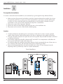
Installation
and Operation Manual
Installation,
Operation, and
Service Information
Aircel
AHLD E-Series Heatless Regenerative
Desiccant Air Dryer
Models AHLD-1000 E, 1250 E, 1500 E, 2000 E, 2500 E, 3000 E,
3500 E, 4500 E, 5000 E
Throughout this manual,
signal words are present to
advise of safety precautions
and/or standard practices.
Obey these signal words as defined
below:
DANGER! - indicates an
imminently hazardous situation
which, if not avoided, will result
in death or serious injury.
WARNING! - indicates a
potentially hazardous situation
which, if not avoided, could
result in death or serious injury.
CAUTION! - indicates a
potentially hazardous situation
which, if not avoided, may result
in minor or moderate injury.
Notice: - used to address
practices not related to personal
injury.
This manual is property of the owner, and should be left with the unit when
start-up is complete. Aircel LLC. reserves the right to change design and
specifications without prior notice.
Aircel AHLD E-Series - Models 1000 - 5000
WARNING!
General Safety Procedures
• Improper installation, operation, or maintenance may contribute to conditions in the work
area or facility that could result in personal injury and product or property damage. Check
that all equipment is properly selected and sized for the intended use.
• Consult and comply with national and local codes relating to fire or explosion and all
other appropriate codes when determining the location and operation of this equipment.
• Safe and efficient operation of the unit depends on proper installation.
• Authorities with jurisdiction should be consulted before installing to verify local codes and
installation procedures. In the absence of such codes, install unit according to the National
Electric Code, NFPA No. 70-latest edition.
• A qualified installation and service agent must complete installation and service of this
equipment.
• DO NOT weld on / to pressure vessel or modify it in any way.
• DO NOT remove, modify, or adjust protective or safety devices.
• Lock out power supply and depressurize system before performing maintenance or service
work.
• DO NOT operate the equipment with the control panel door open.
Notice: For optimum performance, use only Aircel replacement parts.
Notice: For optimum performance, use only original equipment replacement parts.
Notice: For information and notes specific to a custom designed and built dryer, reference the drawing package provided with the unit. See warranty on manual back cover for custom engineered products.
This manual contains specific precautionary statements relative to worker safety.
Read thoroughly and comply as directed. Discuss the use and application of this
equipment with a representative. Instruct all personnel on safe use and maintenance procedures. Understand and obey the following signal words used in this manual.
• DANGER! - indicates an imminently hazardous situation which, if not avoided, will result in death or serious injury.
• WARNING! - indicates a potentially hazardous situation which, if not avoided, could result in death or serious injury.
2
• CAUTION! - indicates a potentially hazardous situation which, if not avoided, may
result in minor or moderate injury.
• Notice: - used to address practices not related to personal injury.
Heatless Regenerative Desiccant Air Dryer
Contents
Safety Statements................................................... 2
Introduction........................................................... 3
Data Sheet.............................................................. 4
Safety Symbols....................................................... 5
General Safety Instructions.................................... 6
Description............................................................ 7
Purpose & Intended Use............................... 7
Features & Options...................................... 8
Inspection on Arrival............................................. 9
Technical Specifications....................................... 10
How it Works Diagram....................................... 11
Installation........................................................... 12
Typical Installation.............................................. 12
Installation Checklist........................................... 13
Start-Up Procedure............................................... 14
Shut-Down Procedure.......................................... 15
Sequence of Operation......................................... 15
Service Information.............................................. 17
Maintenance & Checklists.......................... 17
Troubleshooting................................................... 19
Troubleshooting Table......................................... 20
Desiccant Material Safety Data Sheet................... 22
Aircel Programmable Controller.......................... 27
Electrical Drawings.............................................. 36
Main Power & PLC Input.......................... 36
PLC Output & Sensors............................... 38
Back Panel................................................... 40
Enclosure Layout........................................ 41
Service Notes....................................................... 42
Warranty............................................................. 44
Introduction
Thank you for purchasing Aircel’s AHLD-E Series Heatless Regenerative Desiccant Air Dryer with
Integrated Energy Management Purge Reduction System. You are now the proud owner of one of the finest
desiccant dryers in the market. Aircel AHLD-E series dryers are engineered and manufactured to provide
you with many years of trouble free service and provides energy efficient operation by reducing the overall
dry purge air required for regeneration saving energy and money. To ensure that you get the get first class
service from this equipment, we recommend you take some time and read the contents of this manual.
This manual contains all the information required for installing and maintaining your new equipment. It
also includes the safety procedures and corresponding drawings. We strongly suggest that all personnel
involved with the machine, read the entire contents of the manual before proceeding with the installation or
maintenance activities.
The manufacturer reserves the right to make changes without any prior notification and is not obligated in
any manner. Information in this manual is deemed current at the time of publication and Aircel disclaims all
liability for any errors resulting in any loss or damage.
If you have questions or need additional copies or would like to schedule a Aircel's serviceman visit, contact
your distributor.
Aircel
323 Crisp Circle
Maryville, TN 37801
Toll-Free: (800) 767-4599
Tel: (865) 681-7066
Fax: (865) 681-7069
Sales Information:
[email protected]
Order Entry:
[email protected]
www.AircelDryers.com
3
Aircel AHLD E-Series - Models 1000 - 5000
Data Sheet
Model Number_ _ _ _ _ _ _ _ _ _ _ _ _ _ _ _ _ _ _ _ _ _ _ _ _ _ _ _ _ _ _ _ _ _ _ _ _ _ Serial Number _ _ _ _ _ _ _ _ _ _ _ _ _ _ _ _ _ _ _ _ _ _ _ _ _ _ _ _ _ _ _ _ _ _ _ _ _ _ _ _ _
Dryer Type _ _ _ _ _ _ _ _ _ _ _ _ _ _ _ _ _ _ _ _ _ _ _ _ _ _ _ _ _ _ _ _ _ _ _ _ _ _ _ _ _ Date of Manufacture _ _ _ _ _ _ _ _ _ _ _ _ _ _ _ _ _ _ _ _ _ _ _ _ _ _ _ _ _ _ _ _ _ _ _
Ship Date_ _ _ _ _ _ _ _ _ _ _ _ _ _ _ _ _ _ _ _ _ _ _ _ _ _ _ _ _ _ _ _ _ _ _ _ _ _ _ _ _ _ _ Installation Date _ _ _ _ _ _ _ _ _ _ _ _ _ _ _ _ _ _ _ _ _ _ _ _ _ _ _ _ _ _ _ _ _ _ _ _ _ _ _
Customer Name _ _ _ _ _ _ _ _ _ _ _ _ _ _ _ _ _ _ _ _ _ _ _ _ _ _ _ _ _ _ _ _ _ _ _ _ _ Address _ _ _ _ _ _ _ _ _ _ _ _ _ _ _ _ _ _ _ _ _ _ _ _ _ _ _ _ _ _ _ _ _ _ _ _ _ _ _ _ _ _ _ _ _ _ _
Address Cont’d _ _ _ _ _ _ _ _ _ _ _ _ _ _ _ _ _ _ _ _ _ _ _ _ _ _ _ _ _ _ _ _ _ _ _ _ _ _ _ _ _ _ _ _ _ _ _ _ _ _ _ _ _ _ _ _ _ _ _ _ _ _ _ _ _ _ _ _ _ _ _ _ _ _ _ _ _ _ _ _ _ _ _ _ _ _ _ _ _ _ _
Accessories___________________________________________________________________________________________________________________
Other__________________________________________________________________________________________________________________________
Dryer Inlet Air Flow Rate ________________________________________________________________________________________
Dryer Inlet Temperature __________________________________________________________________________________________
Dryer Ambient Temperature ____________________________________________________________________________________
Dryer Voltage ______________________________________________________________________________________________________
Dryer MCA Minimum Circuit Ampacity _____________________________________________________________________
Dryer MOP Maximum Overcurrent Protection ______________________________________________________________
Dryer Operating Pressure ________________________________________________________________________________________
Dryer Maximum Operating Pressure __________________________________________________________________________
Dryer Vessel Pressure Relief Valve Setting ____________________________________________________________________
Dryer Desiccant Type _____________________________________________________________________________________________
Dryer Desiccant Weight per Vessel _____________________________________________________________________________
Dryer Desiccant Weight Total for System _____________________________________________________________________
Dryer Outlet Dewpoint ___________________________________________________________________________________________
Dryer Control Time Cycle _______________________________________________________________________________________
Dryer EMS RH Sensor Setting (for sensing mid-bed moisture) ___________________________________________
High Dewpoint Setting (option) ________________________________________________________________________________
Demand Cycle Setting (option) _________________________________________________________________________________
Outlet Dewpoint Readout on Display (option) ______________________________________________________________
Electrical Drawing No. ___________________________________________________________________________________________
Mechanical Drawing No. ________________________________________________________________________________________
PLC Software Program No. _____________________________________________________________________________________
Control Air Filter Element No. _________________________________________________________________________________
Inlet Pre-Filter Element No. (option) ___________________________________________________________________________
Outlet After-Filter Element No. (option) _______________________________________________________________________
Inlet Valve __________________________________________________________________________________________________________
Purge Exhaust Valve ______________________________________________________________________________________________
Vessel National Board No. (left and right vessels) __________________________________________________________
Dryer System Weight _____________________________________________________________________________________________
4
Heatless Regenerative Desiccant Air Dryer
Safety Instructions
Safety Symbols Used in Manual
Important Information: Readers of the manual must pay extra attention to
instructions and information succeeding this symbol.
Warning: This indicates that it is dangerous and could result in physical injury and
death if the instructions are not followed correctly.
Electrical Danger High Voltage: This means that there is a risk of electric shock and
only authorized personnel with proper gear must approach it.
High Noise Area: All personnel are required to wear ear protectors before
approaching the vicinity of the equipment.
Hazardous Fumes & Gases: Personnel must wear protective gear to prevent inhaling
of the gases and fumes.
Suspension Points: Look for these symbols before making any attempt to move or
relocate your equipment.
Tips & Suggestions: Following these tips can make your work easier.
Extreme Caution: This indicates that there might be possible risk of material damage
and personnel are advised to exercise extra caution.
5
Aircel AHLD E-Series - Models 1000 - 5000
General Safety Instructions
What You Must Do
1. Certified/authorized electricians must perform electrical work
2. Electrical work must conform to the specifications indicated by Aircel and any local or state laws that
may apply.
3. Personnel must wear appropriate safety gear before working on any electrical or mechanical aspects of
the machine.
4. Appropriate tools have to be used for all installation and maintenance work. If special tools are required
and are not available to the installation crew, contact the factory or your Aircel representative.
5. A copy of the Operation Manual must be made available to all personnel involved with the installation,
operation and maintenance of the equipment.
6. Before performing any maintenance operations on the equipment, the unit must be shut down, isolated,
electrical power removed, and completely depressurized.
7. To ensure compatibility and continued trouble free operation, only genuine Aircel parts must be used.
What You Must Not Do
1. Do not make constructional changes to the unit. Only Aircel or its authorized representatives with the
prior approval can perform any constructional work on the machine.
2. Do not use foreign parts.
3. Compressed air from the dryers is not to be used for breathing purposes – install a breathing air package
to ensure conformance with OSHA regulations
4. Do not disable or disengage any protective equipment used on the machine.
Safe Operating Procedures
1. Pressurize and depressurize compressed air SLOWLY! Always open air valves slowly when pressurizing
the airline system or equipment. Replace air slowly when depressurizing your air system or equipment.
2. Circuit breakers, fusible disconnect, and wiring should conform to national and/or local electrical codes.
Make certain that qualified electrical personnel perform the electrical installation for this unit.
3. Only use original fuses for the rated voltage and current.
4. Shut down the unit in the correct recommended procedure.
5. Before any work on system always Depressurize the unit and remove all electrical power.
6. After shut down, put up warning notice to prevent the unit from being switched “ON” accidentally.
7. Inspect all piping, hoses and connections. Make sure that all hoses are in good condition and are rated
for the correct working pressure. Do not allow hoses to come into contact with oil, chemicals, or sharp
objects.
8. Secure condensate drain lines. Unsecured flexible drain lines may whip violently under pressure and may
cause bodily harm.
Aircel air dryers do not remove carbon monoxide and is not safe for human respiration (breathing).
Breathing air must be at least grade D quality as described in compressed air and gas association (CAGI)
commodity specifications 67.1-1966. User may refer to OSHA 29 CFI 1910.134 for special precautions
and equipment suitable for breathing air applications. Aircel disclaims any liability what so ever for loss,
injury or damage.
6
Heatless Regenerative Desiccant Air Dryer
Product Description
Why We Need Compressed Air Dryers
Untreated compressed air contains many contaminants such as water, compressor oil, pipe scale and
contamination from ambient air. All these contaminants cause excessive corrosion, erosion, freezing and
product contamination to all components that come in contact with the untreated compressed air. A
regenerative type dryer system with all recommended filtration will remove these contaminants to harmless
levels. The end result is that instruments that come in contact with the dry compressed air stay clean and do
not corrode, therefore lasting much longer. Products that may come in contact with clean dry compressed
air are virtually unaffected. Therefore rejection rates are reduced.
Purpose & Intended Use
Aircel Regenerative Desiccant Air Dryers can dry compressed air to -100°F PDP (Pressure Dew Point),
Standard Regenerative Desiccant Air Dryers dry compressed air down to -40°F PDP. The compressed air
stream is passed through a desiccant bed, which removes the moisture through the process of adsorption.
Twin towers filled with desiccant alternate between drying and regeneration either based on the Energy
Management System (EMS) control or a fixed time cycle. Aircel manufactures various types of desiccant air/
gas dryers. These dryers offer fail-safe design in the event of power interruption. Air will continue to flow
through the dryer without deadheading; also purge exhaust valves will close preventing loss of air pressure.
The tower operating status lights and the highest quality non-lubricated air/gas inlet valves will ensure
reliable operation for many years to come.
7
Aircel AHLD E-Series - Models 1000 - 5000
Standard Features
• Integrated Energy Management Purge Reduction System for efficient energy savings and reduced cost of
operation.
• Optimal tower size for low velocities reducing desiccant fluidization, and high contact time for efficient
low dewpoint performance.
• Tower pressure relief valves.
• Standard design capacity based on 100 psig, 100°F inlet air, 100°F ambient air and PDP of -40°F.
• Purge exhaust mufflers for quiet operation.
• Tower pressure gauges for additional visual operation of dryer operation.
• Stainless steel desiccant supports and air diffusers to prevent channeling.
• Counter-current reactivation for efficient desiccant regeneration.
• PLC Controlled Electrical System
• Adjustable (5 min., 10 min.) Cycle times: 10 minute cycle for the standard -40°F PDP outlet dewpoint
systems, 5 minute cycle used in the optional -100°F PDP outlet dewpoint systems.
• Controlled repressurization to slowly repressurize the regenerated vessel to line pressure prior to switch
over preventing desiccant bed movement and attrition.
• Fail safe design: failure of power and/or pilot air causes the purge exhaust valves to close eliminating
loss of air pressure. The System also provides uninterrupted drying air flow preventing a deadheading
affect.
• Control pilot air filter provides clean air to air control system for long trouble-free reliable operation.
• Desiccant towers are designed, fabricated and stamped according to ASME code. (AHLD-70 E and up).
• Desiccant fill and drain ports for ease of desiccant replacement.
• Structural steel frame
• Highly reliable non-lubricated high performance inlet butterfly valves (AHLD-1000 E — AHLD-5000 E)
• Highly reliable angle seat design purge exhaust valves (AHLD-1000 E — AHLD-1500 E).
• Highly reliable non-lubricated high performance purge exhaust butterfly valves (AHLD-1500 E and up).
• Tower operating L.E.D. status lights (Left Tower Drying, Right Tower Drying, Left Tower
Regenerating, Right Tower Regenerating)
• ON/OFF switch and power ON light.
• NEMA 4 weather resistant electrical system construction. Additional Options
•
•
•
•
•
•
8
-100°F outlet pressure dew point
Failure-to-shift alarm (with pressure transducers)
Outlet dewpoint sensor with dewpoint readout on system display
High humidity alarm
Outlet dewpoint 4-20 ma signal
Mounted, piped and wired filtration packages
Heatless Regenerative Desiccant Air Dryer
Inspection on Arrival
All Aircel dryers are tested and operated before
shipment. However, shipping stresses have the
potential to cause damage to the unit. To ensure
smooth installation, it is recommended that
immediately upon receipt of the unit, the system is
checked for the following:
1. Make sure you have received all the crates/
packages that are indicated in the packing slip.
2. Remove the crate and packaging. Inspect the
unit for any visible damage.
3. Report any damage to the delivery carrier.
4. Request a written inspection report from the
Claims Inspector to substantiate the claim.
5. File claims with the delivery carrier.
6. Compare unit received with description of
product ordered. Check the serial plate label
and make sure that it is the correct Model was
ordered. Note the equipment Capacity and
Power Supply requirements and ensure that they
are in accordance with your specifications. The
rated conditions of the dryer are indicated on
the serial plate label. If there is any discrepancy,
contact your representative listed on the manual
back cover.
7. Shipping stresses can loosen connections.
All pipe and tubing connections should be
inspected.
8. Report incomplete shipments to the
delivery carrier and your Aircel service
representative.
CAUTION!
• Do not misuse or modify under any
conditions. Misuse or modification
of this equipment may result in
personal injury.
9
Aircel AHLD E-Series - Models 1000 - 5000
Technical Specifications
How Does it Work? (see diagram 1)
Moisture saturated compressed air enters the
coalescing pre filter (F1) where aerosols are
coalesced then drained via an automatic drain
system. The moist water vapor-laden inlet air
free of liquid water flows to the inlet of the dryer
through the APV (Automatic Piston Valve) (V1)
which diverts the inlet air to one of the towers,
in this example tower (T1). Air flows upward
through the adsorbent bed removing the moisture
vapor; the dried airflow exits the tower through the
outlet valve (V5) flowing to the outlet particulate
after filter (F2, recommend option) which removes
particulates from the air stream. Clean and dry air
now flows to the customer process air distribution
system.
As one tower is drying air, the other tower will be
regenerating (purging) the adsorbent bed. In this
example, tower (T2) will be regenerating. Prior
to regeneration, the exhaust valve (V4) is opened
and the tower is depressurized to near atmospheric
pressure, the tower will now be regenerating.
During the regenerating process a small portion of
dry outlet compressed air is used, 15% on average
based on standard design capacity of 100 psig,
100°F inlet air, 100°F ambient air and PDP of
-40°F. The dry regeneration airflow is channeled
through the outlet orifice to the regenerating tower
(T2) removing moisture from the adsorbent bed and
exists the regenerating tower (T2) through exhaust
valve (V4) and exhaust muffler to ambient. After
regeneration cycle is complete valve (V4) closes
causing tower (T2) to repressurize to line pressure.
Next, the towers will switch when exhaust valve
(V3) begins to open causing tower (T1) to begin
to depressurize and regenerate, simultaneously the
inlet valves (V1) and (V2) will shift causing the inlet
airflow to be diverted to tower (T2) which will now
be the drying tower. This switching process will
continue repeatedly.
The dryer control system is completely automatic
and cycles the system through the drying and
regeneration cycles. The standard cycle drying time
is 5 minutes, regeneration cycle is 4 minutes, and
repressurizing cycle is 1 minute.
The Aircel AHLD E-Series Heatless Dryer
incorporates a unique energy saving control system
to reduce purge air loss with its integrated Energy
Management Purge Reduction System which utilizes
a moisture sensor sampling the air from mid bed of
the on-stream drying tower, after the fixed purge
time is complete the regenerating/purging tower will
repressurize. If the moisture sensor senses a low
moisture condition or low load in the drying tower,
the drying tower will remain in the drying mode
after the fixed drying time cycle for an extended
period of time. The end result is an overall purge
reduction and significant energy savings.
CAUTION!
• Do not misuse or modify under any
conditions. Misuse or modification
of this equipment may result in
personal injury.
10
Heatless Regenerative Desiccant Air Dryer
Diagram 1: How it Works
11
Aircel AHLD E-Series - Models 1000 - 5000
Installation
Pre-requisites for Installation
To ensure a safe and smooth installation, we recommend you go through the steps indicated below:
• Make sure that all personnel involved have read this Operation Manual thoroughly. If you have
any questions, feel free to contact your Aircel representative or the factory and we will be glad
to assist you. If you need help with the commissioning, we will be glad to schedule a factory
serviceman to visit your site and commission the dryer for a nominal fee.
• Have extra copies of the Operation Manuals.
• Special care must be taken while transporting the unit to the installation site.
• Dryer must not be moved or lifted by the attached piping.
Location
• Careful consideration should be given to the location of the dryer in order to assure optimum
results. Ensure that the load bearing weight of the floor is adequate for the weight of the dryer.
• The dryer should be located in an open area and a level ground. Dryer should be bolted to the floor
to eliminate vibrations.
• The ambient temperature should be between 40°F and 100°F. Low temperature could affect the
dryer process and result in high outlet dew point.
• In conditions where the ambient drops below freezing, Aircel recommends the use of heat trace on
any coalescing filter sumps and drain lines and the use of heated type drains.
• Dryer and accompanying filters should be installed with at least 2-5 feet clearance from the
adjoining walls to provide easy access for routine maintenance.
Typical Installation
12
Heatless Regenerative Desiccant Air Dryer
Installation
Only qualified personnel should make electrical and mechanical connections.
Equipment for Installation: This dryer does not need any special tools for installation
Foundation: Dryer should be mounted on a suitably structured flat and level floor or base that is free
from vibration. Special care must be used when lifting the dryer to prevent tip-over
Mounting: Bolt dryer to the foundation using the boltholes provided in the frame.
Piping: Connect the inlet of the dryer to the moist gas from the compressor/receiver/inlet filter. Install
the Inlet piping and the inlet shutoff valve, Install the Outlet piping and the outlet shutoff valve (a union
with a valve by-pass can be installed at the inlet and outlet valves to accommodate isolation of the dryer
for maintenance). Compressed air piping has to be at least the same size as that of the inlet and outlet
connections of the dryer. Larger pipe sizes can be used with reducers.
Back Pressure Regulator: Install backpressure regulator to prevent any possibility of fluidization of the
desiccant bed. When there is a sudden increase in the demand for compressed air downstream of the
dryer, a huge pressure drop develops and can affect the performance of the dryer and the drying material
(desiccant).
Desiccant: Make sure that the dryer towers are filled with desiccant. Larger dryers may have desiccant
shipped separately – in which case, the media has to be filled into the pressure vessels from the desiccant
fill ports. Care must be taken when filling the media and it must be done gradually to prevent powdering.
Muffler: If the event that mufflers have been shipped loose, they must be installed and secured
By-pass: If the dryer is not supplied with optional by-pass valve it is highly recommended that by-pass
valve be installed around the dryer and filters. These by-pass shut-off valves will permit the dryer and
filters to be removed from the compressed air system for servicing without shutting down the entire
compressed air system.
Electrical: Make all electrical connections to the dryer as shown on the wiring diagram. Special care must
be taken in connecting the proper voltage as indicated on the specification sheet and wiring schematic.
Additional Valving/Piping: When installing equipment or components keep in mind the serviceability of
the equipment and provide additional valves to isolate, bypass, and to depressurize as needed.
Exhaust: If you intend to vent your exhaust with additional piping, the discharge piping from the exhaust
should not be piped upward without an arrangement for removing trapped condensate. Make sure that
you do not apply a backpressure on this exhaust system. If exhaust piping is to be extended, try to stay
within 15 to 20 feet and use the next larger pipe size.
Note: It is mandatory that dryer be grounded. Use of your plants frame as a ground may cause problems
with the control. A fused disconnect is not supplied with this equipment therefore one must be supplied
by customer. All electrical fuses, breakers, etc. should be properly sized.
Aircel is not liable for any code violations; component damage, downtime or consequential damage related
to customer supplied electrical components and connections.
13
Aircel AHLD E-Series - Models 1000 - 5000
Start-Up Procedure
At any point during the process of startup or shutdown, you notice anything unusual; we recommend you
refer to the operation manual immediately. If you cannot find the answer in the troubleshooting section,
contact your Aircel representative or the factory at once.
1. Ensure that the dryer is connected to a
suitable compressed air supply. Make sure
that the pressure of the supply is equal to
the normal operating pressure of the dryer.
2. Check to make sure the “shut-off’ valves
are closed and that by-pass valve is open.
3. Close all manual drain/vent valves.
4. Slowly pressurize the dryer by gradually
(slowly) opening the inlet shut-off valve to
the OPEN position.
5. When both towers of the dryer are
completely pressurized, check the complete
system for possible air leaks. Use soap
and water to test all joints and fittings.
If any leaks are detected, immediately
depressurize the unit and correct the leaks.
6. Make certain that any automatic
condensate drain isolation valves are in
the open position so proper condensate
draining can occur.
7. When normal operating pressure is
reached, switch on electrical power (Turn
switch to ON position)
8. With by-pass valve closed, open the outlet
valve slowly to allow air downstream.
9. When energized one of the towers should
depressurize.
10.Check the operation of several cycles
completely by following the control panel
display screen operation, the panel lights
on the electrical box, and the tower
pressure gauges to make certain the dryer
system is operating as displayed. Also
refer to the how it works section, flow
diagram, electrical drawing, dryer control
display screen descriptions, and sequence of
operation in this manual for reference.
11.Check the drain valve for proper operation
and discharge of liquid (filters and
separators, etc.).
12.Near the dryer outlet (APV) valve, check
the control air/ pilot air regulator secondary
pressure, the regulator gauge should read
100 psig. Increase or decrease regulator
knob to achieve a 100 psig control air
secondary pressure reading.
13.Make certain the purge exhaust valves
slowly open within an 8 to 12 second time
period, some adjustment of the flow control
valve attached to the actuator may be
required, after adjustment tighten down the
locking collar.
14.Make certain a slight amount of air flow
is felt at the end of the EMS RH sensor
sample cell exhaust coil tube (this is
normally located at the back of the dryer)
adjust the needle valve to give more or less
flow.
15.Review the dryer system display screen
shots (in this manual) to make certain
the parameters are set as needed in the
customer dryer.
16.Purge air flow is preset and not adjustable.
After the initial startup, the dryer operation is completely automatic. To understand the details of the
operation, we recommend you use the how it works section, flow diagram, electrical drawing, dryer control
display screen descriptions, and sequence of operation in this manual for reference.
14
Heatless Regenerative Desiccant Air Dryer
Shut-Down Procedure
At any point during the process of startup or shutdown, you notice anything unusual; we recommend you
refer to the operation manual immediately. If you cannot find the answer in the troubleshooting section,
contact your Aircel representative or the factory at once.
1. Slowly OPEN the by-pass valve.
2. Slowly CLOSE the Inlet and outlet “shut-off” valves.
3. To depressurize the dryer after the Dryer is isolated. Turn Power ON … a purge exhaust valve will
open and the dryer system starts to depressurize, also the manual vent valve on the outlet afterfilter
can be opened to depressurize the Dryer until the tower pressure gauges read ‘0’ psig.
4. Switch off electrical power after both towers have been depressurized.
Sequence of Operation
Step 1: Vessel 2 Depressurizing (0-5 secs)
Vessel 2 (T2) purge exhaust pilot solenoid valve is energized
which supplies control air to the purge exhaust valve (V4)
which opens slowly, depressurizing vessel 2 (T2). Simultaneously
the inlet valves V1 and V2 shift positions with a pneumatic signal
from vessel 2 (T2) purge exhaust pilot solenoid valve to the inlet
tower selector pneumatic pilot valve which in-turn supplies a
pneumatic signal to the inlet valves to open valve (V1) and
close valve (V2), directing the inlet air to vessel 1(T1) to be
drying the air. The air flows up through the desiccant bed and
exits to the outlet valve (V5) to the outlet particulate filter then
to the customer dry process air system.
Step 2: Vessel 2 Regenerating (6-240 secs)
Step 2 is a continuation of step 1 except vessel 2 (T2) will be
regenerating, vessel 2 (T2) purge exhaust valve (V4) is still open,
vessel 1 (T1) is drying the inlet air. A small portion of dry outlet air
from vessel 1 (T1) (15% average based on standard design capacity
of 100 psig, 100°F inlet air, 100°F ambient air and PDP of -40°F)
is taken through a small orifice in the outlet line and used to
regenerate the desiccant bed in vessel 2 (T2) until 240 seconds
has been reached.
Step 3: Vessel 2 Repressurizing (241-300 secs)
Vessel 2 (T2) purge exhaust pilot solenoid valve will de-energize
causing vessel 2 (T2) purge exhaust valve (V4) to close, this allows
vessel 2 (T2) to repressurize to line pressure, since air continues flowing
though the small outlet orifice pressurizing vessel 2 (T2). The inlet tower
selector pneumatic pilot valve maintains the inlet valve (V1 & V2) positions.
15
Aircel AHLD E-Series - Models 1000 - 5000
Sequence of Operation (cont’d)
Step 4: Extended Drying Vessel 1
A few seconds before the end of repressurization the AHLD E-SERIES
Controller’s integrated Energy Management Purge Reduction System
looks at the moisture sensor, if the moisture load is low enough,
vessel 1 (T1) will continue to dry for an extended drying period
until the moisture load has reached a set high level, the controller
will then advance to step 5 and the vessels will switch. This feature
reduces the overall purge consumption saving energy and money.
Step 5: Vessel 1 Depressurizing (0-5 secs)
Vessel 1 (T1) purge exhaust pilot solenoid valve is energized which supplies
control air to the purge exhaust valve (V3) which opens slowly, depressurizing
vessel 1 (T1). Simultaneously the inlet valves V2 and V1 shift positions
with a pneumatic signal from vessel 1 (T1) purge exhaust pilot solenoid
valve to the inlet tower selector pneumatic pilot valve which in-turn
supplies a pneumatic signal to the inlet valves to open valve (V2) and
close valve (V1), directing the inlet air to vessel 2 (T2) to be drying the air.
The air flows up through the desiccant bed and exits to the outlet valve (V6)
to the outlet particulate filter then to the customer dry process air system.
Step 6: Vessel 1 Regenerating (6-240 secs)
Step 6 is a continuation of step 5 except vessel 1 (T1) will be regenerating,
vessel 1 (T1) purge exhaust valve (V3) is still open, vessel 2 (T2) is drying the
inlet air. A small portion of dry outlet air from vessel 2 (15% average based
on standard design capacity of 100 psig, 100°F inlet air, 100°F ambient air
and PDP of -40°F) is taken through a small orifice in the outlet line and used to
regenerate the desiccant bed in vessel 1 (T1) until 240 seconds has been reached. Step 7: Vessel 1 Repressurizing (241-300 secs)
Vessel 1 (T1) purge exhaust pilot solenoid valve will de-energize causing
vessel 1 (T1) purge exhaust valve (V3) to close, this allows vessel 1 (T1)
to repressurize to line pressure, since air continues flowing though the small
outlet orifice pressurizing vessel 1 (T1). The inlet tower selector pneumatic pilot
valve maintains the inlet valve (V2 and V1) positions.
Step 8: Extended Drying Vessel 2
A few seconds before the end of repressurization the AHLD E-SERIES
Controller’s integrated Energy Management Purge Reduction System looks
at the moisture sensor, if the moisture load is low enough, vessel 2 (T2) will
continue to dry for an extended drying period until the moisture load has reached a
set high level, the controller will then advance to step 1 and the vessels will switch.
This feature reduces the overall purge consumption saving energy and money.
16
Heatless Regenerative Desiccant Air Dryer
Maintenance
Prior to performing any maintenance on the dryer, all personnel are strongly advised to familiarize
themselves with the equipment by reading the entire contents of this operation manual. Aircel strongly
recommends the strict adherence of all the safety procedures prior to any performing any maintenance
activity on the dryer.
A. The pressure differential indicator referred to as the “Delta-P” is a very good indicator of the state
of the filter elements. Maintenance personnel must pay attention to these to keep the dryer running
with full efficiency Change filter elements on a regular basis, once a year maximum for a 1-shift
operation. Change more frequently if operating 2 or 3 shifts such as every 6 months.
B. The useful life of a filter element depends on the quality of air. Free open areas for input and
exhaust will ensure lesser intake of dirt and particles.
C. Powdered desiccant can accumulate in the muffler and increase the backpressure in the regenerating
tower change mufflers on a regular basis typically every 2-3 months for optimum performance.
D. Oil and oil vapor can drastically reduce the life of the desiccant. Take precautions to eliminate all
traces of oil from the airflow
E. Fluctuating dewpoint indicates uneven drying and regeneration between the towers, an exhaust
valve may not be working properly or muffler may be clogged or dirty, also vessel diffuser screen
may be clogged.
Weekly Checklist
1. Check all drain valves, prefilter, afterfilter and separators
2. Check any pressure differential indicators (Delta-P) on the pre-filter and afterfilter (filter elements
should still be changed on regular basis once a year maximum for a 1 shift operation. Change more
frequently if operating 2 or 3 shifts such as every 6 months.).
3. Check dryer for correct operation.
4. Verify dryer is purging at the purge exhaust, after dryer depressurizes.
5. Check the dewpoint (if available) to ensure the dewpoint is being achieved.
6. Check backpressure in regenerating tower, if more than a few psig on the pressure gauge, clean
or replace exhaust mufflers (Change mufflers on a regular basis typically every 2-3 months for
optimum performance).
17
Aircel AHLD E-Series - Models 1000 - 5000
Maintenance (cont’d)
Semi-Annual Checklist
1. Remove and inspect all filters for excessive particulate loading and physical damage – if required
replace prefilters, afterfilters, pilot air filter and mufflers (filter elements should still be changed on
regular basis once a year maximum for a 1 shift operation. Change more frequently if operating 2
or 3 shifts such as every 6 months.).
2. Check pressure differential indicator and if it turns red, replace the element.
3. Remove exhaust mufflers. Knock out excess particulate and back flow with dry compressed air.
If particulate cannot be removed completely change the exhaust mufflers. Check backpressure
in regenerating tower, if more than a few psig on the pressure gauge, clean or replace exhaust
mufflers. (Change mufflers on a regular basis typically every 2-3 months for optimum performance)
4. Check desiccant condition. Powder in the mufflers is a indication of the status of the desiccant.
5. Check all solenoid valves - coil condition and control circuit.
6. Check dryer operation.
7. Inspect and clean inlet and outlet APV (Automatic Piston Valves).
Annual Checklist
1.
2.
3.
4.
5.
Replace elements in prefilters, afterfilters, and pilot air filter.
Replace mufflers.
Recalibrate dewpoint analyzer probe (if used) send back to factory for recalibration.
Check inlet and outlet valve seals clean or replace as needed.
Check dryer for proper operation.
WARNING!
• Before any service or maintenance
work is performed on the
refrigerated air dryer system,
disconnect power supply and lock
out power supply and depressurize
system.
• Follow proper lock out/tag out
procedures before performing
service or maintenance work.
• Follow all safety procedures prior to
performing any maintenance activity
on the dryer.
18
Heatless Regenerative Desiccant Air Dryer
Troubleshooting
The following section briefly discusses the various faults that can occur in the dryer, the reason of the
fault and how it can be rectified. If you do not find the solution to your problem, contact your Aircel
representative or the factory. All necessary safety and precautionary steps must be followed before
attempting to perform any of the recommended measures to resolve any faults in the air dryer.
Before any attempt is made to undertake any action, the machine must be shut down, isolated,
depressurized, and powered down. Follow the shut down procedures.
Note: Some troubleshooting will have to be done while system is pressurized and
energized so use extreme caution.
1.
2.
3.
4.
5.
6.
7.
Depressurize the unit
Check to make sure if the unit has been damaged externally or if any part is missing.
Check if there is proper power supply and if it corresponds to that mentioned on the data plate.
Check to see if there is power at all the electrical connections in the machine and the proper voltage.
Check if control air is available and the proper pressure at all pneumatically operated components.
Make sure all shut-off valves are in the correct position.
Check the airflow, inlet temperature and pressure and make sure it falls within the operating range.
19
Aircel AHLD E-Series - Models 1000 - 5000
Troubleshooting (cont’d)
Problem
High Dewpoint
High-Pressure Drop
High Back Pressure in
Regenerating Tower
Probable Cause
Remedy
High inlet air flow
Reduce inlet air flow
Inlet air temperature above
design spec
Reduce inlet air temperature to design spec
Poor pre-filtration
Check pre-filter element, replace if needed
Inlet air pressure below
design spec
Increase pressure to the dryer
Desiccant contaminated
Replace desiccant
Outlet Purge flow orifice
may be clogged
Dismantle outlet orifice and clean out the
orifice
Back pressure in
regenerating chambers
Mufflers are clogged, install new mufflers
Exhaust valve(s) not fully
opening or closing
Check pilot valve and pilot air supply,
dismantle and clean exhaust valve, check flow
control valve attached to purge exhaust valve
actuator may not be adjusted properly (should
be adjusted so exhaust valve opens within a
8-12 second time period)
Inlet valve leaking
Dismantle and clean, replace seals if needed
No input power
Check that dryer is on with correct voltage
No input power
Check that dryer is on with correct voltage
Controller failure
Check, replace if needed
Low inlet pressure
Increase inlet pressure to design pressure
Desiccant dusting
High inlet flow velocities due to high flow
Inlet prefilter dirty
Inspect and replace as needed
High inlet flow rate
Reduce inlet flow rate to meet dryer spec
Outlet filter dirty
Inspect and replace as needed
Desiccant diffuser screens
clogged
Inspected and clean if needed
Purge muffler clogged
Clean and replace if needed
Desiccant diffuser screens
clogged
Restrictive purge exhaust
piping
20
Inspected and clean if needed
Clean and replace with larger pipe if required
Heatless Regenerative Desiccant Air Dryer
Troubleshooting (cont’d)
Problem
Dryer Fails to
Shift Towers
Probable Cause
Remedy
Exhaust valves(s) not
functioning
Check pilot valve and pilot air supply, dismantle
and clean exhaust valve check flow control valve
attached to purge exhaust valve actuator may
not be adjusted properly (should be adjusted so
exhaust valve opens within a 8-12 second time
period)
No input power
Check that dryer is on with correct voltage.
Controller failure
Check, replace if needed
Pilot air supply restricted
Check pilot filter, and pilot tubing restriction.
Outlet Purge flow orifice
may be clogged
Dismantle outlet purge flow orifice and clean
out orifice
Inlet valve malfunction
Outlet valve malfunction
Purge Failure
Pressurization
Failure
Dismantle, clean, and reinstall replace seals if
needed
Dismantle, clean, and reinstall replace valve if
needed
Purge muffler clogged
Remove and clean, replace if needed
Outlet Purge flow orifice
may be clogged
Dismantle outlet purge flow orifice and clean
out orifice
Controller failure
Check, replace if needed
Exhaust valves(s) not
functioning
Check pilot valve and pilot air supply, dismantle
and clean exhaust valve purge exhaust valve
actuator may not be adjusted properly (should
be adjusted so exhaust valve opens within a 8-12
second time period) check control system
Outlet Purge flow orifice
may be clogged
Dismantle outlet purge flow orifice and clean
out orifice
Exhaust valves(s) not
functioning
Check pilot valve and pilot air supply, dismantle
and clean exhaust valve purge exhaust valve
actuator may not be adjusted properly (should
be adjusted so exhaust valve opens within a 8-12
second time period) check control system
21
Aircel AHLD E-Series - Models 1000 - 5000
Desiccant Material Safety Data Sheet
Safety data sheet
F200
Revision date : 2009/12/04
Version: 3.0
Page: 1/5
(30286124/MDS_GEN_US/EN)
1. Substance/preparation and company identification
Company
BASF CORPORATION
100 Campus Drive
Florham Park, NJ 07932, USA
24 Hour Emergency Response Information
CHEMTREC: 1-800-424-9300
BASF HOTLINE: 1-800-832-HELP
2. Composition/information on ingredients
CAS Number
1333-84-2
Content (W/W)
>= 94.0 - <= 100.0 %
Chemical name
Aluminum oxide (Al2O3), hydrate
3. Hazard identification
Emergency overview
CAUTION: MAY CAUSE EYE, SKIN AND RESPIRATORY TRACT IRRITATION.
May cause difficulty breathing.
Prolonged or repeated contact may result in dermatitis.
Contact with the eyes or skin may cause mechanical irritation.
Contains material which may indicate/cause the possibility of sensory and pulmonary irritation.
Avoid contact with the skin, eyes and clothing.
Avoid inhalation of dusts.
Use with local exhaust ventilation.
Wear a NIOSH-certified (or equivalent) particulate respirator.
Wear safety glasses with side-shields.
Wear chemical resistant protective gloves.
Wear protective clothing.
Eye wash fountains and safety showers must be easily accessible.
Potential health effects
Primary routes of exposure
Routes of entry for solids and liquids include eye and skin contact, ingestion and inhalation. Routes of entry for
gases include inhalation and eye contact. Skin contact may be a route of entry for liquified gases.
4. First-aid measures
If inhaled:
Keep patient calm, remove to fresh air. If necessary, give oxygen. If not breathing, give artificial respiration.
Seek medical attention if necessary.
22
Heatless Regenerative Desiccant Air Dryer
Desiccant Material Safety Data Sheet
Safety data sheet
F200
Revision date : 2008/12/04
Version: 3.0
Page: 2/5
(30286124/MDS_GEN_US/EN)
If on skin:
After contact with skin, wash immediately with plenty of water and soap. Consult a doctor if skin irritation
persists.
If in eyes:
In case of contact with the eyes, rinse immediately for at least 15 minutes with plenty of water. Immediate
medical attention required.
If swallowed:
No hazards anticipated. If large quantities are ingested, seek medical advice.
5. Fire-fighting measures
Flash point:
Additional information:
Use extinguishing measures to suit surroundings.
Non-flammable.
Hazards during fire-fighting:
No particular hazards known.
Protective equipment for fire-fighting:
Wear self-contained breathing apparatus and chemical-protective clothing.
NFPA Hazard codes:
Health : 0
Fire: 0
Reactivity: 1
Special:
6. Accidental release measures
Cleanup:
Vacuum up spilled product. Place into suitable container for disposal.
7. Handling and storage
Handling
General advice:
Avoid dust formation in confined areas. Avoid contact with the skin, eyes and clothing. Ensure adequate
ventilation.
Storage
General advice:
Keep container tightly closed in a cool, well-ventilated place.
Storage stability:
Keep container dry.
8. Exposure controls and personal protection
Components with workplace control parameters
Aluminum oxide (Al2O3),
hydrate
OSHA
ACGIH
PEL 5 mg/m3 Respirable fraction ; PEL 15 mg/m3 Total
dust ;
TWA value 1 mg/m3 Respirable fraction ;
23
Aircel AHLD E-Series - Models 1000 - 5000
Desiccant Material Safety Data Sheet
Safety data sheet
F200
Revision date : 2008/12/04
Version: 3.0
Page: 3/5
(30286124/MDS_GEN_US/EN)
Advice on system design:
Provide local exhaust ventilation to control dust. Provide local exhaust ventilation to maintain recommended
P.E.L.
Personal protective equipment
Respiratory protection:
Wear a NIOSH-certified (or equivalent) particulate respirator. Observe OSHA regulations for respirator use (29
CFR 1910.134). Wear appropriate certified respirator when exposure limits may be exceeded.
Hand protection:
Wear chemical resistant protective gloves., Consult with glove manufacturer for testing data.
Eye protection:
Safety glasses with side-shields.
Body protection:
Body protection must be chosen based on level of activity and exposure.
9. Physical and chemical properties
Form:
Odour:
Colour:
pH value:
Melting point:
Boiling point:
Vapour pressure:
Density:
Bulk density:
Partitioning coefficient
n-octanol/water (log Pow):
Viscosity, dynamic:
Solubility in water:
powder, granules, pellets, balls
odourless
off-white
9.4 - 10.1
2,050 °C
No data
No data
No data
approx. 650 kg/m3
38.0 - 52 lb/ft3
( 68 °F)
No data
10. Stability and reactivity
Substances to avoid:
water
Hazardous reactions:
The product is chemically stable.
Addition of water leads to increase in temperature.
11. Toxicological information
Oral:
Information on: Aluminum oxide
LD50/rat: > 5,000 mg/kg (OECD Guideline 401)
----------------------------------
24
available.
available.
available.
available.
No data available.
insoluble
Heatless Regenerative Desiccant Air Dryer
Desiccant Material Safety Data Sheet
Safety data sheet
F200
Revision date : 2008/12/04
Version: 3.0
Page: 4/5
(30286124/MDS_GEN_US/EN)
Skin irritation:
Information on: Aluminum oxide
rabbit: non-irritant (OECD Guideline 404)
----------------------------------
12. Ecological information
Information on: Aluminum oxide
Acute and prolonged toxicity to fish:
DIN 38412 Part 15 static
golden orfe/LC50 (96 h): > 500 mg/l
The product has not been tested. The statement has been derived from products of a similar structure and
composition.
---------------------------------Information on: Aluminum oxide
Acute toxicity to aquatic invertebrates:
OECD Guideline 202, part 1 static
Daphnia magna (48 h): > 100 mg/l
----------------------------------
13. Disposal considerations
Waste disposal of substance:
Dispose of in accordance with local authority regulations.
Check for possible recycling.
Disposal requirements are dependent on the hazard classification and will vary by location and the type of
disposal selected.
All waste materials should be reviewed to determine the applicable hazards (testing may be necessary).
14. Transport information
Land transport
USDOT
Not classified as a dangerous good under transport regulations
Sea transport
IMDG
Not classified as a dangerous good under transport regulations
Air transport
IATA/ICAO
Not classified as a dangerous good under transport regulations
15. Regulatory information
Federal Regulations
25
Aircel AHLD E-Series - Models 1000 - 5000
Desiccant Material Safety Data Sheet
Safety data sheet
F200
Revision date : 2008/12/04
Version: 3.0
Page: 5/5
(30286124/MDS_GEN_US/EN)
Registration status:
TSCA, US
released / listed
OSHA hazard category:
ACGIH TLV established
SARA hazard categories (EPCRA 311/312): Acute
SARA 313:
CAS Number
1333-84-2
Chemical name
Aluminum oxide (Al2O3), hydrate
State regulations
State RTK
CAS Number
1333-84-2
Chemical name
Aluminum oxide (Al2O3), hydrate
State RTK
MA, NJ, PA
16. Other information
HMIS III rating
Health: 1
Flammability: 0
Physical hazard: 1
HMIS uses a numbering scale ranging from 0 to 4 to indicate the degree of hazard. A value of zero means that the substance
possesses essentially no hazard; a rating of four indicates high hazard.
Local contact information
[email protected]
IMPORTANT: WHILE THE DESCRIPTIONS, DESIGNS, DATA AND INFORMATION CONTAINED HEREIN
ARE PRESENTED IN GOOD FAITH AND BELIEVED TO BE ACCURATE , IT IS PROVIDED FOR YOUR
GUIDANCE ONLY. BECAUSE MANY FACTORS MAY AFFECT PROCESSING OR APPLICATION/USE, WE
RECOMMEND THAT YOU MAKE TESTS TO DETERMINE THE SUITABILITY OF A PRODUCT FOR YOUR
PARTICULAR PURPOSE PRIOR TO USE. NO WARRANTIES OF ANY KIND, EITHER EXPRESSED OR
IMPLIED, INCLUDING WARRANTIES OF MERCHANTABILITY OR FITNESS FOR A PARTICULAR
PURPOSE, ARE MADE REGARDING PRODUCTS DESCRIBED OR DESIGNS, DATA OR INFORMATION
SET FORTH, OR THAT THE PRODUCTS, DESIGNS, DATA OR INFORMATION MAY BE USED WITHOUT
INFRINGING THE INTELLECTUAL PROPERTY RIGHTS OF OTHERS. IN NO CASE SHALL THE
DESCRIPTIONS, INFORMATION, DATA OR DESIGNS PROVIDED BE CONSIDERED A PART OF OUR
TERMS AND CONDITIONS OF SALE. FURTHER, YOU EXPRESSLY UNDERSTAND AND AGREE THAT
THE DESCRIPTIONS, DESIGNS, DATA, AND INFORMATION FURNISHED BY BASF HEREUNDER ARE
GIVEN GRATIS AND BASF ASSUMES NO OBLIGATION OR LIABILITY FOR THE DESCRIPTION,
DESIGNS, DATA AND INFORMATION GIVEN OR RESULTS OBTAINED, ALL SUCH BEING GIVEN AND
ACCEPTED AT YOUR RISK.
END OF DATA SHEET
26
Heatless Regenerative Desiccant Air Dryer
Aircel Programmable Controller
System display shows the dryer operations and provides the user the ability to change certain dryer settings.
Red LED: Common alarm light
Text Display
Standard alarms: EMS Humidity
Probe failure and Drain fault
Optional alarms: High Humidity,
Dew Point probe failure and
Failure to Shift
Red LED: Energy Savings
Active Light
DEL Key
Up Arrow Key
ESC Key
ALT Key
Right Arrow Key
Left Arrow Key
On Key
* Key
Down Arrow Key
27
Aircel AHLD E-Series - Models 1000 - 5000
Aircel Programmable Controller
Step 1: Vessel 2 Depressurizing (0-5 secs)
Vessel 2 (T2) purge exhaust pilot solenoid valve is energized
which supplies control air to the purge exhaust valve (V4)
which opens slowly, depressurizing vessel 2 (T2). Simultaneously
the inlet valves V1 and V2 shift positions with a pneumatic signal
from vessel 2 (T2) purge exhaust pilot solenoid valve to the inlet
tower selector pneumatic pilot valve which in-turn supplies a
pneumatic signal to the inlet valves to open valve (V1) and close valve (V2), directing the inlet air
to vessel 1(T1) to be drying the air. The air flows up through the desiccant bed and exits to the
outlet valve (V5) to the outlet particulate filter then to the customer dry process air system. Step 2:
Vessel 2 Regenerating (6-240 secs)
Step 2 is a continuation of step 1 except vessel 2 (T2) will be
regenerating, vessel 2 (T2) purge exhaust valve (V4) is still open,
vessel 1 (T1) is drying the inlet air. A small portion of dry outlet air
from vessel 1 (T1) (15% average based on standard design capacity
of 100 psig, 100°F inlet air, 100°F ambient air and PDP of -40°F)
is taken through a small orifice in the outlet line and used to
regenerate the desiccant bed in vessel 2 (T2) until 240 seconds has been reached. The screen also
shows the relative humidity reading as well as the (optional) dew point when applicable. The timer
on this step counts to 240 seconds (4-minutes). There is a warning sign that will flash in the upper
right hand portion of the screen for any alarm. There is also a red LED alarm light that will flash
on the PLC display for any alarm. The user must scroll to the alarm screen to view the alarms
(press the left arrow once from the main screen to view the alarm screen). Step 3: Vessel 2 Repressurizing (241-300 secs)
Vessel 2 (T2) purge exhaust pilot solenoid valve will de-energize
causing vessel 2 (T2) purge exhaust valve (V4) to close, this
allows vessel 2 (T2) to repressurize to line pressure, since air
continues flowing though the small outlet orifice pressurizing
vessel 2 (T2). The inlet tower selector pneumatic pilot valve
maintains the inlet valve (V1 & V2) positions.
Step 4: Extended Drying Vessel 1
A few seconds before the end of repressurization the AHLD
E-SERIES Controller’s integrated Energy Management Purge
Reduction System looks at the moisture sensor, if the moisture
load is low enough, vessel 1 (T1) will continue to dry for an
extended drying period until the moisture load has reached a set
high level, the controller will then advance to step 5 and the vessels
will switch. This feature reduces the overall purge consumption saving energy and money. The
extended drying cycle timer will count to 30 minutes unless the EMS relative humidity sensor is
higher than the set point. After 30 minutes, the unit will switch and continue normal operation
until the next extended savings step. At the start of each extended savings step the PLC checks for
faults, EMS relative humidity sensor value and high outlet dewpoint setting (optional) to ensure if
the dryer needs to continue drying and the dryer will go into extended drying. If the dryer needs to
continue to the next step to regenerate, the extended savings step 4 will be skipped.
28
Heatless Regenerative Desiccant Air Dryer
Aircel Programmable Controller
Step 5: Vessel 1 Depressurizing (0-5 secs)
Vessel 1 (T1) purge exhaust pilot solenoid valve is energized
which supplies control air to the purge exhaust valve (V3) which
opens slowly, depressurizing vessel 1 (T1). Simultaneously the
inlet valves V2 and V1 shift positions with a pneumatic signal
from vessel 1 (T1) purge exhaust pilot solenoid valve to the inlet
tower selector pneumatic pilot valve which in-turn supplies a
pneumatic signal to the inlet valves to open valve (V2) and close valve (V1), directing the inlet air
to vessel 2 (T2) to be drying the air. The air flows up through the desiccant bed and exits to the
outlet valve (V6) to the outlet particulate filter then to the customer dry process air system.
Step 6: Vessel 1 Regenerating (6-240 secs)
Step 6 is a continuation of step 5 except vessel 1 (T1) will be
regenerating, vessel 1 (T1) purge exhaust valve (V3) is still open,
vessel 2 (T2) is drying the inlet air. A small portion of dry outlet
air from vessel 2 (15% average based on standard design capacity
of 100 psig, 100°F inlet air, 100°F ambient air and PDP of -40°F)
is taken through a small orifice in the outlet line and used to
regenerate the desiccant bed in vessel 1 (T1) until 240 seconds
has been reached.
Step 7: Vessel 1 Repressurizing (241-300 secs)
Vessel 1 (T1) purge exhaust pilot solenoid valve will de-energize
causing vessel 1 (T1) purge exhaust valve (V3) to close, this
allows vessel 1 (T1) to repressurize to line pressure, since air
continues flowing though the small outlet orifice pressurizing
vessel 1 (T1). The inlet tower selector pneumatic pilot valve '
maintains the inlet valve (V2 and V1) positions.
Step 8: Extended Drying Vessel 2
A few seconds before the end of repressurization the AHLD
E-SERIES Controller’s integrated Energy Management Purge
Reduction System looks at the moisture sensor, if the moisture
load is low enough, vessel 2 (T2) will continue to dry for an
extended drying period until the moisture load has reached a
set high level, the controller will then advance to step 1 and the
vessels will switch. This feature reduces the overall purge
consumption saving energy and money. The extended drying
cycle timer will count to 30 minutes unless the EMS relative humidity sensor is higher than the
set point. After 30 minutes, the unit will switch and continue normal operation until the next
extended savings step. At the start of each extended savings step the PLC checks for faults, EMS
relative humidity sensor value and high outlet dewpoint setting (optional) to ensure if the dryer
needs to continue drying and the dryer will go into extended drying. If the dryer needs to continue
to the next step to regenerate, the extended savings step 4 will be skipped.
29
Aircel AHLD E-Series - Models 1000 - 5000
Aircel Programmable Controller
Main Screen Navigation
LEFT/RIGHT
ALARM SCREEN
LEFT/RIGHT
CONTROL MENU
Control Menu Navigation
LEFT/RIGHT
MAIN SCREEN
30
LEFT/RIGHT
SETTINGS MENU Heatless Regenerative Desiccant Air Dryer
Aircel Programmable Controller
Control Menu Operation
• Push OK to engage the menu
• Scroll to the desired selection and Push OK
CONTROL MENU
Settings Screen Operation
For use with optional outlet dewpoint display and high humidity alarm.
SETTINGS SCREEN
• To engage, Push OK then scroll to the desired
set point to be changed
• Push OK on the set point to be changed and use
the up or down arrows to change the set point
• Push OK to complete the change and ESC to
de-select the screen. Push ESC again to exit to
the main screen or use the left or right arrows to
scroll to the next screen.
31
Aircel AHLD E-Series - Models 1000 - 5000
Aircel Programmable Controller
Time Control Menu Navigation
This time cycle control menu allows the user to choose between a 10 minute standard time cycle and a
shorter 5 minute cycle for lower dewpoint option.
TIME CYCLE CONTROL
LEFT/RIGHT
SETTINGS MENU LEFT/RIGHT
ANALOG SCREEN
Time Control Menu Operation
TIME CONTROL MENU
• To change the time cycle, Push OK then scroll
to the time cycle to be selected. Push OK then
Push ESC.
• When changes are complete, Push ESC to exit
changes. Push ESC again to return to the main
screen.
32
Heatless Regenerative Desiccant Air Dryer
Aircel Programmable Controller
Analog Screen Navigation
The analog screen simply displays the analog output signals
ANALOG SCREEN
LEFT/RIGHT
LEFT/RIGHT
TIME CONTROL SCREEN
HOURS OF OPERATION
Hours of Operation Screen Navigation
The hours of operation screen gives the user the amount of run time as well as the total amount of hours
saved with the energy management system.
HOURS OF OPERATION
LEFT/RIGHT
ANALOG SCREEN
LEFT/RIGHT
ALARM SCREEN
33
Aircel AHLD E-Series - Models 1000 - 5000
Aircel Programmable Controller
Alarm Screen Navigation
ALARM SCREEN
LEFT/RIGHT
TOTAL HOURS OF OPERATION
LEFT/RIGHT
MAIN MENU
Alarm Pop-Ups
• No Alarm: alarm has been corrected
• High Outlet Dew Point (option): dew point has reached set point (check desiccant, prefilters,
control system)
• Failure to Shift (option): tower did not properly repressurize
• Bad Probe: the EMS sensor has reached an out of range signal (check sensor and cable)
34
Heatless Regenerative Desiccant Air Dryer
Aircel Programmable Controller
Alarm Pop-Up Screens
No Alarm is the normally closed state of the common alarm relay.
The Drain Fault is an alarm that triggers when there is no air
present on the drain or when the liquid level has reached a point
that needs to Drain and cannot. The drain will also fault if there is
a loss of power to the drain.
The Bad RH Probe is an alarm that shows when the relative
humidity (EMS) probe is out of range. This can be either high out
of range or low out of range. When this happens, the signal has
either been lost or the sensor may need to be replaced.
The Bad DEW-P Probe is the alarm for the dew point sensor probe
out of range. The out of range can be either high or low. This
can be either a complete loss of signal/voltage, the resistor can be
disconnected or the sensor may need to be calibrated.
The High Humidity Alarm is an alarm that is visible when the
dew point is higher than the set point. The set point for the high
humidity alarm can be changed but it is not recommended.
The FTS Alarm (Failure-to-Shift) is an alarm that is present when
a vessel does not depressurize correctly or if a vessel that is to be
drying does not have a pressure at or above a certain set pressure.
35
Aircel AHLD E-Series - Models 1000 - 5000
Electrical Drawings
Main Power & PLC Input: All AHLD E Models
36
Heatless Regenerative Desiccant Air Dryer
Electrical Drawings
Main Power & PLC Input: All AHLD E Models
37
Aircel AHLD E-Series - Models 1000 - 5000
Electrical Drawings
PLC Output & Sensors: All AHLD E Models
38
Heatless Regenerative Desiccant Air Dryer
Electrical Drawings
PLC Output & Sensors: All AHLD E Models
39
Aircel AHLD E-Series - Models 1000 - 5000
Electrical Drawings
Back Panel: All AHLD E Models
40
Heatless Regenerative Desiccant Air Dryer
Electrical Drawings
Enclosure Layout: All AHLD E Models
41
Aircel AHLD E-Series - Models 1000 - 5000
Service Notes
Date
42
Service Performed
Notes
Heatless Regenerative Desiccant Air Dryer
Service Notes
Date
Service Performed
Notes
43
Aircel Compressed Air & Gas Warranty
Aircel warrants that its Standard Refrigerated Air Dryers are free from defects in materials and
workmanship for two years from the date of invoice. Warranty coverage for this time period will
be parts and labor for the first year and parts only for the second. Custom engineered products,
desiccant dryers, chillers and nitrogen generators are warranted to be free from defects in materials
and workmanship for one year from date of invoice. Warranty coverage for this time period will be for
parts and labor.
Aircel warranty excludes damages due to corrosion, lack of proper maintenance, incorrect installation,
modification, or misapplication of equipment. Routine maintenance or adjustment required under
normal operation as outlined in the Aircel operation and maintenance manuals are not covered under
warranty.
Once Aircel has been given adequate opportunity to remedy any defects in material or workmanship in
accordance with Aircel Warranty Policy and Procedures, Aircel retains the sole option to accept return
of the goods, with freight paid by the purchaser, and to refund the purchase price for the goods after
confirming the goods are returned undamaged and in usable condition. Such a refund will be the full
extent of Aircel liability. Aircel shall not be liable for any other costs, expenses or damages whether
direct, indirect, special, incidental, consequential or otherwise. The terms of this warranty may be
modified only by a special warranty document signed by a CEO, General Manager or Vice President
of Aircel.
There exist no other representations, warranties or guarantees except as stated in this paragraph and
all other warranties, including merchantability and fitness for a particular purpose whether express or
implied, are hereby expressly excluded and disclaimed.
Parts and Service
For genuine Aircel replacement parts, call:
800-767-4599
www.AircelDryers.com
For faster service, have unit’s model and serial number,
part number, description, and quantity available.
Aircel LLC. is a leading designer and
manufacturer of dryer systems and components.
Aircel LLC.
323 Crisp Circle
Maryville, TN 37801
[email protected]
[email protected]
www.AircelDryers.com
© 2013 Aircel LLC.
Printed in USA
August 2013


![Electrolux Lux 7000 Bagged Canister Vacuum - C:\Users\Jason&Kim\Desktop\Lux7000[1]](http://vs1.manualzilla.com/store/data/007257175_1-4f8df6fa53bec1c3cae9b6f5e2e6b2de-150x150.png)