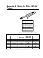
1
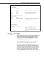
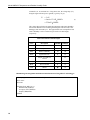
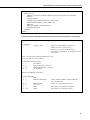
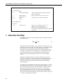
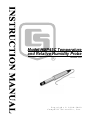
Model HMP45C Temperature
and Relative Humidity Probe
Revision: 3/09
C o p y r i g h t © 1 9 9 0 - 2 0 0 9
C a m p b e l l S c i e n t i f i c , I n c .
Warranty and Assistance
The MODEL HMP45C TEMPERATURE AND RELATIVE HUMIDITY
PROBE is warranted by CAMPBELL SCIENTIFIC, INC. to be free from
defects in materials and workmanship under normal use and service for twelve
(12) months from date of shipment unless specified otherwise. Batteries have
no warranty. CAMPBELL SCIENTIFIC, INC.'s obligation under this
warranty is limited to repairing or replacing (at CAMPBELL SCIENTIFIC,
INC.'s option) defective products. The customer shall assume all costs of
removing, reinstalling, and shipping defective products to CAMPBELL
SCIENTIFIC, INC. CAMPBELL SCIENTIFIC, INC. will return such
products by surface carrier prepaid. This warranty shall not apply to any
CAMPBELL SCIENTIFIC, INC. products which have been subjected to
modification, misuse, neglect, accidents of nature, or shipping damage. This
warranty is in lieu of all other warranties, expressed or implied, including
warranties of merchantability or fitness for a particular purpose. CAMPBELL
SCIENTIFIC, INC. is not liable for special, indirect, incidental, or
consequential damages.
Products may not be returned without prior authorization. The following
contact information is for US and International customers residing in countries
served by Campbell Scientific, Inc. directly. Affiliate companies handle
repairs for customers within their territories. Please visit
www.campbellsci.com to determine which Campbell Scientific company
serves your country. To obtain a Returned Materials Authorization (RMA),
contact CAMPBELL SCIENTIFIC, INC., phone (435) 753-2342. After an
applications engineer determines the nature of the problem, an RMA number
will be issued. Please write this number clearly on the outside of the shipping
container. CAMPBELL SCIENTIFIC's shipping address is:
CAMPBELL SCIENTIFIC, INC.
RMA#_____
815 West 1800 North
Logan, Utah 84321-1784
CAMPBELL SCIENTIFIC, INC. does not accept collect calls.
HMP45C Table of Contents
PDF viewers note: These page numbers refer to the printed version of this document. Use
the Adobe Acrobat® bookmarks tab for links to specific sections.
1. General Description.....................................................1
2. Specifications ..............................................................2
2.1 Temperature Sensor ..................................................................................2
2.2 Relative Humidity Sensor.........................................................................2
3. Installation....................................................................3
3.1 Siting.........................................................................................................3
3.2 Assembly and Mounting...........................................................................3
4. Wiring............................................................................5
5. Example Programs ......................................................6
6. Long Lead Lengths......................................................9
7. Absolute Humidity .....................................................12
8. Sensor Maintenance..................................................15
9. Troubleshooting ........................................................16
10. References ...............................................................16
Appendix
A. Wiring for Older HMP45C Probes .......................... A-1
Figures
3-1. HMP45C and 41003-5 Radiation Shield on a Tripod Mast ....................4
3-2. HMP45C and 41003-5 Radiation Shield on a CM200 Series Crossarm.4
A-1. HMP45C Probe to Datalogger Connections...................................... A-1
i
HMP45C Table of Contents
Tables
1-1. Recommended Lead Lengths ................................................................. 1
4-1. Connections for Single-Ended Measurements........................................ 5
4-2. Connections for Differential Measurements........................................... 6
4-3. Power Connections using SW12V Peripherals....................................... 6
5-1. Calibration for Temperature ................................................................... 7
5-2. Calibration for Relative Humidity .......................................................... 7
5-3. Wiring for Single-ended Measurement Examples.................................. 7
6-1. Wiring for Differential Measurement Examples .................................. 10
7-1. Wiring for Vapor Pressure Examples ................................................... 13
8-1. Chemical Tolerances of HMP45C........................................................ 16
A-1. Connections for Single-Ended Measurements for Old Wiring
Configuration ...................................................................................... A-1
A-2. Connections for Differential Measurements for Old Wiring
Configurations .................................................................................... A-2
ii
Model HMP45C Temperature and
Relative Humidity Probe
1. General Description
The HMP45C Temperature and Relative Humidity probe contains a Platinum
Resistance Temperature detector (PRT) and a Vaisala HUMICAP® 180
capacitive relative humidity sensor.
The -L option on the model HMP45C Temperature and Relative Humidity
probe (HMP45C-L) indicates that the cable length is user specified. This
manual refers to the sensor as the HMP45C.
The HMP45C can be powered continuously or the power may be switched to
conserve battery life. The HMP45C consumes less than 4 milliamperes current
at 12 volts. Approximately 0.15 seconds is required for the sensor to warm up
after power is switched on. At measurement rates slower than once per
second, the overall power consumption (datalogger and sensors) may be
reduced by switching power to the HMP45C. Most current Campbell
Scientific dataloggers have a built-in switched 12 volts that can be used to
control power.
The CR9000, CR510, CR500, CR7, CR10 and 21X dataloggers do not have a
built-in switched 12 volts. Users with these dataloggers can power the sensor
continuously or purchase the model SW12V to switch power.
NOTE
Prior to April 2004, the HMP45C included a power switching
circuit in the cable. The in-cable switching circuit was
discontinued because in most cases it is no longer necessary and
it made the cable difficult to route through the entry port on
environmental enclosures.
Lead length for the HMP45C is specified when the sensor is ordered. Table
1-1 gives the recommended lead lengths.
TABLE 1-1. Recommended Lead Lengths
2 m Height
Atop a tripod or tower via a 2 ft crossarm such as the CM202
Mast/Leg
CM202
CM6
CM10
CM110
CM115
CM120
UT10
UT20
UT30
9'
11'
11'
14'
14'
19'
24'
14'
24'
37'
Note: Add two feet to the cable length if you are mounting the enclosure on the leg base of a light-weight tripod.
The HMP45C ships with:
(1) Adjustment Screwdriver from mfg
(1) Calibration Sheet
(1) Resource CD
1
Model HMP45C Temperature and Relative Humidity Probe
2. Specifications
Operating Temperature: -40°C to +60°C
Storage Temperature: -40°C to +80°C
Probe Length: 25.4 cm (10 in.)
Probe Body Diameter: 2.5 cm (1 in.)
Filter: 0.2 μm Teflon membrane
Filter Diameter: 1.9 cm (0.75 in.)
Power Consumption: <4 mA @ 12 V
Supply Voltage: 7 to 35 VDC
Settling Time: 0.15 seconds
2.1 Temperature Sensor
Sensor: 1000 Ω PRT, IEC 751 1/3 Class B
Temperature Measurement Range: -40°C to +60°C
Temperature Output Signal range: 0.008 to 1.0 V
Temperature Accuracy:
Error ( o C)
0.4
0.2
0.0
-0.2
-0.4
-40
-20
0
20
40
60
Temperature ( o C)
2.2 Relative Humidity Sensor
Sensor: HUMICAP® 180
Relative Humidity Measurement Range: 0 to 100% non-condensing
RH Output Signal Range: 0.008 to 1 VDC
Accuracy at 20°C
±2% RH (0 to 90% Relative Humidity)
±3% RH (90 to 100% Relative Humidity)
Temperature Dependence of Relative Humidity Measurement: ±0.05% RH/°C
Typical Long Term Stability: Better than 1% RH per year
Response Time (at 20°C, 90% response): 15 seconds with membrane filter
NOTE
2
The black outer jacket of the cable is Santoprene® rubber. This
compound was chosen for its resistance to temperature extremes,
moisture, and UV degradation. However, this jacket will
support combustion in air. It is rated as slow burning when
tested according to U.L. 94 H.B. and will pass FMVSS302.
Local fire codes may preclude its use inside buildings.
Model HMP45C Temperature and Relative Humidity Probe
3. Installation
3.1 Siting
Sensors should be located over an open level area at least 9 m (EPA) in
diameter. The surface should be covered by short grass, or where grass does
not grow, the natural earth surface. Sensors should be located at a distance of
at least four times the height of any nearby obstruction, and at least 30 m
(EPA) from large paved areas. Sensors should be protected from thermal
radiation, and adequately ventilated.
Standard measurement heights:
1.5 m +/- 1.0 m (AASC)
1.25 – 2.0 m (WMO)
2.0 m (EPA)
2.0 m and 10.0 m temperature difference (EPA)
See Section 10 for a list of references that discuss temperature and relative
humidity sensors.
3.2 Assembly and Mounting
Tools Required:
•
•
•
•
1/2” open end wrench
small screw driver provided with datalogger
UV resistant cable ties
small pair of diagonal-cutting pliers
The HMP45C must be housed inside a radiation shield when used in the field.
The 41003-5 Radiation shield has a U-bolt for attaching the shield to tripod
mast / tower leg (Figure 3-1), or CM200 series crossarm (Figure 3-2). The
radiation shield ships with the U-bolt configured for attaching the shield to a
vertical pipe. Move the U-bolt to the other set of holes to attach the shield it to
a crossarm.
Loosen the split-nut on the bottom plate of the 41003-5. Remove the yellow
protective cap on the HMP45C, and insert the sensor into the shield. Tighten
the split-nut to secure the sensor in the shield. Route the sensor cable to the
instrument enclosure. Secure the cable to the tripod/tower using cable ties.
The HMP45C must be housed inside a radiation shield when used in the field.
The 41003-5 Radiation Shield (Figure 3-1 and 3-2) mounts to a tripod mast,
tower leg, or CM200 series crossarm.
3
Model HMP45C Temperature and Relative Humidity Probe
41003-5
Split Nut
U-bolt
FIGURE 3-1. HMP45C and 41003-5 Radiation Shield on a Tripod Mast
CM200 Series Crossarm
FIGURE 3-2. HMP45C and 41003-5 Radiation Shield
on a CM200 Series Crossarm
4
Model HMP45C Temperature and Relative Humidity Probe
4. Wiring
Connections to Campbell Scientific dataloggers are given in Tables 4-1
through 4-3. The probe can be measured by two single-ended or differential
analog input channels.
CAUTION
When measuring the HMP45C with single-ended
measurements, the purple or white and black leads must
both be connected to AG on the CR10(X) and
on the CR1000, CR5000, and
CR500/CR510 or to
CR23X. Doing otherwise will connect the datalogger’s
analog and power ground planes to each other, which in
some cases can cause offsets on low-level analog
measurements. To avoid 4 mA flowing into analog ground,
switch the sensor on/off for its own measurement.
TABLE 4-1. Connections for Single-Ended Measurements
Color
Description
CR10X
CR1000,
CR3000,
CR800,
CR5000,
CR23X
Yellow
Temperature
Signal
Single-Ended
Input
Single-Ended
Input
Single-Ended
Input
Single-Ended
Input
Blue
Relative Humidity
Signal
Single-Ended
Input
Single-Ended
Input
Single-Ended
Input
Single-Ended
Input
White
Signal Reference
AG
AG
Black
Power Ground
AG
AG
Shield
Shield
G
G
Red
Power
Continuous/Switched
SW12V
CR10X Power Control
if using SW12V
channel on datalogger
Jumper from
SW12V Control to
Control Port
SW12V
CR10,
CR510,
CR500
21X, CR7
12V/SW12V*
12V/SW12V*
*On these dataloggers switched power is only available with the SW12V peripheral.
5
Model HMP45C Temperature and Relative Humidity Probe
TABLE 4-2. Connections for Differential Measurements
Color
Description
CR10X
CR1000,
CR3000,
CR800,
CR5000,
CR23X
Yellow
Temperature
Signal
Differential
Input – H
Differential
Input – H
Differential
Input – H
Differential
Input – H
Jumper to
White
Temperature Signal
Reference
Differential
Input – L
Differential
Input – L
Differential
Input – L
Differential
Input – L
Blue
Relative Humidity Signal
Differential
Input – H
Differential
Input – H
Differential
Input – H
Differential
Input – H
White
Signal Reference
Differential
Input – L
Differential
Input – L
Differential
Input – L
Differential
Input – L
Black
Power Ground
G
G
G
Shield
Shield
G
Red
Power
Continuous/Switched
12V/SW12V
CR10X Power Control
if using SW12V
channel on datalogger
Jumper from
SW12V
Control
to Control Port
CR10,
CR510,
CR500
21X, CR7
G
12V/SW12V
12V/SW12V*
12V/SW12V*
*On these dataloggers switched power is only available with the SW12V peripheral.
TABLE 4-3. Power Connections using SW12V Peripherals
HMP45C
SW12V Peripheral
Datalogger
Color
Description
Terminal
Wire
Red
Power
SW12V
Red
12 V
Black
Power Ground
GND
Black
G*
Green
Control Port
*The black wire of the SW12V should be connected to the type of datalogger
ground channel recommended for the HMP45C black wire as listed in Table
4-1 and Table 4-2.
5. Example Programs
This section is for users who write their own datalogger programs. A
datalogger program to measure this sensor can be created using Campbell
Scientific’s Short Cut Program Builder software. You do not need to read this
section to use Short Cut.
6
Model HMP45C Temperature and Relative Humidity Probe
The temperature and relative humidity signals from the HMP45C can be
measured using a single-ended analog measurement or a differential analog
measurement.
Use a single-ended analog measurement when the HMP45C signal lead length
is less than 6.1 m (20 ft.) or if the probe will be turned on and off under
datalogger control between measurements. For lead lengths greater than 6.1 m
(20 ft.) or when the probe will be continuously powered, use a differential
analog measurement. For a discussion on errors caused by long lead lengths
see Section 6.
The HMP45C output scale is 0 to 1000 millivolts for the temperature range of
-40°C to +60°C and for the relative humidity range of 0 to 100%. Tables 5-1
and 5-2 provide calibration information for temperature and relative humidity.
TABLE 5-1. Calibration for Temperature
Units
Multiplier
(degrees mV-1)
Offset
(degrees)
Celsius
0.1
-40
Fahrenheit
0.18
-40
TABLE 5-2. Calibration for Relative Humidity
Units
Multiplier
(% mV-1)
Offset
(%)
Percent
0.1
0
Fraction
0.001
0
TABLE 5-3. Wiring for Single-ended
Measurement Examples
Color
Description
CR1000
CR10(X)
Yellow
Temperature
SE 2 (1L)
SE 3 (2H)
Blue
Relative Humidity
SE 1 (1H)
SE 4 (2L)
White
Signal Reference
AG
Jumper from
SW12V Control
C1
Red
Power
SW12V
SW12 V
Black
Power Ground
AG
Clear
Shield
G
7
Model HMP45C Temperature and Relative Humidity Probe
CR1000 Program using Single-Ended Measurement Instructions Using SW12V on Datalogger
'CR1000 program to measure HMP45C with single-ended measurements
Public AirTC
Public RH
DataTable(Temp_RH,True,-1)
DataInterval(0,60,Min,0)
Average(1,AirTC,IEEE4,0)
Sample(1,RH,IEEE4)
EndTable
BeginProg
Scan(1,Sec,1,0)
'HMP45C Temperature & Relative Humidity Sensor measurements AirTC and RH:
SW12 (1 )
Delay(0,150,mSec)
VoltSE(AirTC,1,mV2500,2,0,0,_60Hz,0.1,-40.0)
VoltSE(RH,1,mV2500,1,0,0,_60Hz,0.1,0)
SW12 (0)
If RH>100 And RH<108 Then RH=100
CallTable(Temp_RH)
NextScan
EndProg
CR10(X) Program using Single-Ended Measurement Instructions Using SW12V on Datalogger
;Turn the HMP45C on.
;
01: Do (P86)
1: 41
Set Port 1 High
;Jumper wire from SW12V control to C1
;Orange wire (C1) if older wiring
;Green wire (C1) if using SW12V device
;For CR23X or CR5000 use 49 for SW12V internal
;control port
;Pause 150 mSec before making measurements so the
;probe can stabilize on true readings.
;
02: Excitation with Delay (P22)
1: 1
Ex Channel
2: 0
Delay W/Ex (units = 0.01 sec)
3: 15
Delay After Ex (units = 0.01 sec)
4: 0
mV Excitation
8
Model HMP45C Temperature and Relative Humidity Probe
;Measure the HMP45C temperature.
;
03: Volt (SE) (P1)
1: 1
Reps
2: 5
2500 mV Slow Range
3:
4:
5:
6:
3
1
.1
-40
SE Channel
Loc [ T_C
Mult
Offset
]
;See Table 5-1 for alternative multipliers
;See Table 5-1 for alternative offsets
;Measure the HMP45C relative humidity.
;
04: Volt (SE) (P1)
1: 1
Reps
2: 5
2500 mV Slow Range
3:
4:
5:
6:
4
2
.1
0
;CR510, CR500 (2500mv); CR23X (1000 mV);
21X, CR7 (5000 mV)
;Yellow wire (SE 3), white or purple wire (AG)
SE Channel
Loc [ RH_pct
Mult
Offset
;Turn the HMP45C off.
;
05: Do (P86)
1: 51
Set Port 1 Low
;CR510, CR500 (2500 mV); CR23X (1000 mV);
21X, CR7 (5000 mV)
;Blue wire (SE 4), white or purple wire (AG)
]
;See Table 5-2 for alternative multipliers
;Jumper wire from SW12V control to C1
;Orange wire (C1) if older wiring
;Green wire (C1) if using SW12V device
;For CR23X or CR5000 use 59 for SW12V internal
;control port
6. Long Lead Lengths
This section describes the error associated with measuring the HMP45C with a
single-ended measurement if the probe has a long cable. To avoid these
problems, CSI recommends measuring the HMP45C using a differential
analog measurement (Instruction 2) when long lead lengths are required.
Generic datalogger connections for measuring the HMP45C using a
differential measurement are given in Table A-2.
Understanding the details in this section are not required for the general
operation of the HMP45C with Campbell Scientific’s dataloggers.
The signal reference (white or purple) and the power ground (black) are in
common inside the HMP45C. When the HMP45C temperature and relative
humidity are measured using a single-ended analog measurement, both the
signal reference and power ground are connected to ground at the datalogger.
The signal reference and power ground both serve as the return path for 12 V.
There will be a voltage drop along those leads because the wire itself has
resistance. The HMP45C draws approximately 4 mA when it is powered. The
wire used in the HMP45C (P/N 9721) has resistance of 27.7 Ω/1000 feet.
Since the signal reference and the power ground are both connected to ground
at the datalogger, the effective resistance of those wires together is half of 27.7
9
Model HMP45C Temperature and Relative Humidity Probe
Ω/1000 feet, or 13.9 Ω/1000 feet. Using Ohm’s law, the voltage drop (Vd),
along the signal reference/power ground, is given by Eq. (1).
Vd
= I ∗R
= 4 mA ∗ 13.9 Ω 1000 ft
(1)
= 55.6 mV 1000 ft
This voltage drop will raise the apparent temperature and relative humidity
because the difference between the signal and signal reference lead, at the
datalogger, has increased by Vd. The approximate error in temperature and
relative humidity is 0.56°C and 0.56% per 100 feet of cable length,
respectively.
TABLE 6-1. Wiring for
Differential Measurement Examples
Color
Description
CR1000
CR10(X)
Yellow
Temperature
2H
2H
Jumper to 1L
2L
2L
Blue
Relative Humidity
1H
1H
White
Signal Reference
1L
1L
Jumper from SW12V
Control
C1
Red
Power
SW12 V
SW12 V
Black
Power Ground
G
G
Clear
Shield
G
CR1000 Program using Differential Measurement Instructions Using SW12V on Datalogger
'CR1000 program to measure HMP45C with differential measurements
Public AirTC
Public RH
DataTable(Temp_RH,True,-1)
DataInterval(0,60,Min,0)
Average(1,AirTC,IEEE4,0)
Sample(1,RH,IEEE4)
EndTable
10
Model HMP45C Temperature and Relative Humidity Probe
BeginProg
Scan(1,Sec,1,0)
'HMP45C Temperature & Relative Humidity Sensor measurements AirTC and RH:
SW12 (1 )
Delay(0,150,mSec)
VoltDiff (AirTC,1,mV2500,2,True,0,_60Hz,0.1,-40)
VoltDiff (RH,1,mV2500,1,True,0,_60Hz,0.1,0)
SW12 (0)
If RH>100 And RH<108 Then RH=100
CallTable(Temp_RH)
NextScan
EndProg
CR10(X) Program using Differential Measurement Instructions Using SW12V on Datalogger
;Turn the HMP45C on.
;
01: Do (P86)
1: 41
Set Port 1 High
;Jumper wire from SW12V control to C1
;Orange wire (C1) if older wiring
;Green wire (C1) if using SW12V device
;For CR23X or CR5000 use 49 for SW12V internal
;control port
;Pause 150 mSec before making measurements so the
;probe can stabilize on true readings.
;
02: Excitation with Delay (P22)
1: 1
Ex Channel
2: 0
Delay W/Ex (units = 0.01 sec)
3: 15
Delay After Ex (units = 0.01 sec)
4: 0
mV Excitation
;Measure the HMP45C temperature.
;
03: Volt (Diff) (P2)
1: 1
Reps
2: 5
2500 mV Slow Range
3:
4:
5:
6:
2
1
.1
-40
DIFF Channel
Loc [ T_C
]
Mult
Offset
;CR510, CR500 (2500mv); CR23X (1000 mV);
21X, CR7 (5000 mV)
;Yellow wire (2H), jumper (2L to 1L)
;See Table 5-1 for alternative multipliers
;See Table 5-1 for alternative offsets
11
Model HMP45C Temperature and Relative Humidity Probe
;Measure the HMP45C relative humidity.
;
04: Volt (Diff) (P2)
1: 1
Reps
2: 5
2500 mV Slow Range
3:
4:
5:
6:
1
2
.1
0
DIFF Channel
Loc [ RH_pct ]
Mult
Offset
;Turn the HMP45C off.
;
05: Do (P86)
1: 51
Set Port 1 Low
;CR510, CR500 (2500mv); CR23X (1000 mV);
21X, CR7 (5000 mV)
;Blue wire (1H), white or purple wire (1L)
;See Table 5-2 for alternative multipliers
;Jumper wire from SW12V control to C1
;Orange wire (C1) if older wiring
;Green wire (C1) if using SW12V device
;For CR23X or CR5000 use 59 for SW12V internal
;control port
7. Absolute Humidity
The HMP45C measures the relative humidity. Relative humidity is defined by
the equation below:
RH =
e
∗ 100
es
(2)
where RH is the relative humidity, e is the vapor pressure in kPa , and es is the
saturation vapor pressure in kPa. The vapor pressure, e, is an absolute measure
of the amount of water vapor in the air and is related to the dew point
temperature. The saturation vapor pressure is the maximum amount of water
vapor that air can hold at a given air temperature. The relationship between
dew point and vapor pressure, and air temperature and saturation vapor
pressure are given by Goff and Gratch (1946), Lowe (1977), and Weiss
(1977).
When the air temperature increases, so does the saturation vapor pressure.
Conversely, a decrease in air temperature causes a corresponding decrease in
saturation vapor pressure. It follows then from Eq. (2) that a change in air
temperature will change the relative humidity, without causing a change
absolute humidity.
For example, for an air temperature of 20°C and a vapor pressure of 1.17 kPa,
the saturation vapor pressure is 2.34 kPa and the relative humidity is 50%. If
the air temperature is increased by 5°C and no moisture is added or removed
from the air, the saturation vapor pressure increases to 3.17 kPa and the
relative humidity decreases to 36.9%. After the increase in air temperature,
there is more energy to vaporize the water. However, the actual amount of
water vapor in the air has not changed. Thus, the amount of water vapor in the
air, relative to saturation, has decreased.
12
Model HMP45C Temperature and Relative Humidity Probe
Because of the inverse relationship between relative humidity and air
temperature, finding the mean relative humidity is meaningless. A more useful
quantity is the mean vapor pressure. The mean vapor pressure can be
computed on-line by the datalogger as shown in the following examples.
TABLE 7-1. Wiring for Vapor Pressure Examples
Color
Description
CR1000
CR10(X)
Yellow
Temperature
SE 2 (1L)
SE 3 (2H)
Blue
Relative Humidity
SE 1 (1H)
SE 4 (2L)
White
Signal Reference
AG
Jumper from
SW12V Control
C1
Red
Power
SW12V
SW12 V
Black
Power Ground
AG
Clear
Shield
G
CR1000 Program that Computes Vapor Pressure and Saturation Vapor Pressure
'CR1000 program that calculates Vapor Pressure
Public AirTC
Public RH
Public RH_Frac, e_Sat, e_kPa
DataTable(Temp_RH,True,-1)
DataInterval(0,60,Min,0)
Average(1,AirTC,IEEE4,0)
Sample(1,RH,IEEE4)
Sample(1,e_kPa,IEEE4)
EndTable
BeginProg
Scan(1,Sec,1,0)
'HMP45C Temperature & Relative Humidity Sensor measurements AirTC and RH:
SW12 (1 )
Delay(0,150,mSec)
VoltSE(AirTC,1,mV2500,2,0,0,_60Hz,0.1,-40.0)
VoltSE(RH,1,mV2500,1,0,0,_60Hz,0.1,0)
SW12 (0)
If RH>100 And RH<108 Then RH=100
'Calculate Vapor Pressure
'Convert RH percent to RH Fraction
RH_Frac = RH * 0.01
'Calculate Saturation Vapor Pressure
13
Model HMP45C Temperature and Relative Humidity Probe
SatVP(e_Sat, AirTC)
'Compute Vapor Pressure, RH must be a fraction
e_kPa = e_Sat * RH_Frac
CallTable(Temp_RH)
NextScan
EndProg
CR10(X) Program that Computes Vapor Pressure and Saturation Vapor Pressure
;Turn the HMP45C on.
;
01: Do (P86)
1: 41
Set Port 1 High
;Jumper wire from SW12V control to C1
;Orange wire (C1) if older wiring
;Green wire (C1) if using SW12V device
;For CR23X or CR5000 use 49 for SW12V internal
;control port
;Pause 150 mSec before making measurements so the
;probe can stabilize on true readings.
;
02: Excitation with Delay (P22)
1: 1
Ex Channel
2: 0
Delay W/Ex (units = 0.01 sec)
3: 15
Delay After Ex (units = 0.01 sec)
4: 0
mV Excitation
;Measure the HMP45C temperature.
;
03: Volt (SE) (P1)
1: 1
Reps
2: 5
2500 mV Slow Range
3:
4:
5:
6:
3
1
.1
-40
SE Channel
Loc [ T_C
Mult
Offset
]
;Measure the HMP45C relative humidity.
;
04: Volt (SE) (P1)
1: 1
Reps
2: 5
2500 mV Slow Range
3:
4:
5:
6:
14
4
2
.001
0
;CR510, CR500 (2500mv); CR23X (1000 mV);
21X, CR7 (5000 mV)
;Yellow wire (SE 3), white or purple wire (AG)
SE Channel
Loc [ RH_frac ]
Mult
Offset
;CR510, CR500 (2500mv); CR23X (1000 mV);
21X, CR7 (5000 mV)
;Blue wire (SE 4), white or purple wire (AG)
Model HMP45C Temperature and Relative Humidity Probe
;Turn the HMP45C off.
;
05: Do (P86)
1: 51
Set Port 1 Low
;Compute the saturation vapor pressure.
;The temperature must be in degrees Celsius.
;
06: Saturation Vapor Pressure (P56)
1: 1
Temperature Loc [ T_C
2: 3
Loc [ e_sat ]
;Jumper wire from SW12V control to C1
;Orange wire (C1) if older wiring
;Green wire (C1) if using SW12V device
;For CR23X or CR5000 use 59 for SW12V internal
;control port
]
;Compute the vapor pressure.
;Relative humidity must be a fraction.
;
07: Z=X*Y (P36)
1:
3 X Loc [ e_sat ]
2:
2 Y Loc [ RH_frac ]
3:
4 Z Loc [ e
]
8. Sensor Maintenance
The HMP45C Probe requires minimal maintenance. Check monthly to make
sure the radiation shield is free from debris. The black screen at the end of the
sensor should also be checked for contaminates.
When installed in close proximity to the ocean or other bodies of salt water
(e.g., Great Salt Lake), a coating of salt (mostly NaCl) may build up on the
radiation shield, sensor, filter and even the chip. NaCl has an affinity for
water. The humidity over a saturated NaCl solution is 75%. A buildup of salt
on the filter or chip will delay or destroy the response to atmospheric humidity.
The filter can be rinsed gently in distilled water. If necessary, the chip can be
removed and rinsed as well. Do not scratch the chip while cleaning.
Long term exposure of the HUMICAP® relative humidity sensor to certain
chemicals and gases may affect the characteristics of the sensor and shorten its
life. Table 8-1 lists the maximum ambient concentrations, of some chemicals,
that the HUMICAP® can be exposed to.
15
Model HMP45C Temperature and Relative Humidity Probe
TABLE 8-1. Chemical Tolerances of HMP45C
Chemical
Concentration (PPM)
Organic solvents
1000 to 10,000
Aggressive chemicals
(e.g. SO2, H2SO4, H2S,
HCl, Cl2, etc.)
1 to 10
Weak Acids
100 to 1000
Bases
10,000 to 100,000
Recalibrate the HMP45C annually. Obtain an RMA number before returning
the HMP45C to Campbell Scientific for recalibration.
9. Troubleshooting
Symptom: -9999, NAN, -40 deg C, or 0 % relative humidity
1.
Check that the sensor is wired to the correct excitation and analog input
channels as specified by the measurement instructions.
2.
Verify the Range code is correct for the datalogger type.
3.
Verify the red power wire is correctly wired to the 12V, Switched 12V, or
SW12V module. The terminal the wire is connected to will depend on the
datalogger program.
Connect the red wire to a 12V terminal to constantly power the sensor for
troubleshooting purposes. With the red wire connected to12V, a
voltmeter can be used to check the output voltage for temperature and
relative humidity on the yellow and blue wires respectively (temperature
°C = mV * 0.1 – 40.0; relative humidity % = mV * 0.1).
Symptom: Incorrect temperature or relative humidity
1.
Verify the multiplier and offset parameters are correct for the desired
units (Table 5-1).
10. References
Goff, J. A. and S. Gratch, 1946: Low-pressure properties of water from -160°
to 212°F, Trans. Amer. Soc. Heat. Vent. Eng., 51, 125-164.
Lowe, P. R., 1977: An approximating polynomial for the computation of
saturation vapor pressure, J. Appl. Meteor., 16, 100-103.
Weiss, A., 1977: Algorithms for the calculation of moist air properties on a
hand calculator, Amer. Soc. Ag. Eng., 20, 1133-1136.
16
Appendix A. Wiring for Older HMP45C
Probes
Color
Description
Yellow
Temperature Signal
Blue
Relative Humidity Signal
Purple
Signal Reference
Orange
Power Control
Red
Power
Black
Power Ground
Shield
Shield
FIGURE A-1. HMP45C Probe to Datalogger Connections
TABLE A-1. Connections for Single-Ended Measurements for Old Wiring Configuration
CR1000, CR3000
CR800, CR9000,
CR23X
21X, CR7
Color
Description
CR10(X), CR510,
CR500
Yellow
Temperature
Single-Ended Input
Single-Ended Input
Single-Ended Input
Blue
Relative Humidity
Single-Ended Input
Single-Ended Input
Single-Ended Input
Purple
Signal Reference
AG
Orange
Power Control
Control Port
Control Port
Control Port
Red
Power
12 V
12 V
12 V
Black
Power Ground
AG
Clear
Shield
G
A-1
Appendix A. Wiring for Older HMP45C Probes
TABLE A-2. Connections for Differential Measurements for Old Wiring Configurations
CR1000, CR3000
CR800, CR9000,
CR23X
21X, CR7
Color
Description
CR10(X), CR510,
CR500
Yellow
Temperature
Differential Input (H)
Differential Input (H)
Differential Input (H)
Jumper to
Purple
Signal Reference
Differential Input (L)
Differential Input (L)
Differential Input (L)
Blue
Relative Humidity
Differential Input (H)
Differential Input (H)
Differential Input (H)
Purple
Signal Reference
Differential Input (L)
Differential Input (L)
Differential Input (L)
Orange
Power Control
Control Port
Control Port
Control Port
Red
Power
12 V
12 V
12 V
Black
Power Ground
G
G
Clear
Shield
G
This is a blank page.
A-2
Campbell Scientific Companies
Campbell Scientific, Inc. (CSI)
815 West 1800 North
Logan, Utah 84321
UNITED STATES
www.campbellsci.com • [email protected]
Campbell Scientific Africa Pty. Ltd. (CSAf)
PO Box 2450
Somerset West 7129
SOUTH AFRICA
www.csafrica.co.za • [email protected]
Campbell Scientific Australia Pty. Ltd. (CSA)
PO Box 444
Thuringowa Central
QLD 4812 AUSTRALIA
www.campbellsci.com.au • [email protected]
Campbell Scientific do Brazil Ltda. (CSB)
Rua Luisa Crapsi Orsi, 15 Butantã
CEP: 005543-000 São Paulo SP BRAZIL
www.campbellsci.com.br • [email protected]
Campbell Scientific Canada Corp. (CSC)
11564 - 149th Street NW
Edmonton, Alberta T5M 1W7
CANADA
www.campbellsci.ca • [email protected]
Campbell Scientific Centro Caribe S.A. (CSCC)
300 N Cementerio, Edificio Breller
Santo Domingo, Heredia 40305
COSTA RICA
www.campbellsci.cc • [email protected]
Campbell Scientific Ltd. (CSL)
Campbell Park
80 Hathern Road
Shepshed, Loughborough LE12 9GX
UNITED KINGDOM
www.campbellsci.co.uk • [email protected]
Campbell Scientific Ltd. (France)
Miniparc du Verger - Bat. H
1, rue de Terre Neuve - Les Ulis
91967 COURTABOEUF CEDEX
FRANCE
www.campbellsci.fr • [email protected]
Campbell Scientific Spain, S. L.
Psg. Font 14, local 8
08013 Barcelona
SPAIN
www.campbellsci.es • [email protected]
Please visit www.campbellsci.com to obtain contact information for your local US or International representative.