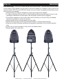
1
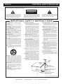
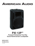
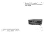
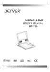
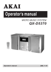
PPA-210
User Guide
and Reference Manual
3/10
6122 S. Eastern Ave
Los Angeles, CA 90040
www.AmericanAudio.us
PPA-210
CONTENTS
MAIN FEATURES....................................................................................................................................2
ELECTRICAL PRECAUTIONS................................................................................................................3
SAFETY PRECAUTIONS........................................................................................................................5
Unpacking....................................................................................................................................6
introduction.........................................................................................................................6
set-up precaution...........................................................................................................................6
CONTROLS and FUNCTIONS............................................................................................................10
Connectors..............................................................................................................12
SET UP..................................................................................................................................................13
CLEANING......................................................................................................................15
Troubleshooting......................................................................................................................15
WARRANTY.........................................................................................................................................16
SPECIFICATIONS.....................................................................................................................18
PPA-210 Main Features
• 4 Mono & 2 Stereo Channel Inputs
• Stereo Main Outputs
• Trim With Peak LED, 3-Band EQ, Aux/EFX, & Pan For Mono Input
• Main L/R, Aux Return, Tape Level
• 24-Bit DSP Effect, 100 Presets, EFX On/Off & EFX Level
• Tape With PFL Switch, HP/Control Room & Phantom Power
• 4 Mono Ch. Inputs, Mic Input (XLR), 1/4” Line Inputs (TRS)
• For Stereo Input (Ch 7-Ch 8) RCA Line Inputs or Mini Jack TRS Inputs
• 1/4” Phone Jack For Main, Aux Send, EFX Send, Control Room & Headphone
• Jack For Tape & 1/4” Phone Jack For Footswitch
©American
Audio® - www.americanaudio.us - PPA-210 Instruction Manual Page 2
PPA-210
ELECTRICAL SAFETY PRECAUTIONS
WARNING: TO PREVENT FIRE OR ELECTRIC
SHOCK HAZARD, DO NOT EXPOSE THIS
UNIT TO RAIN, LIQUIDS, OR MOISTURE
The serial and model number for this unit is
located on the rear panel. Please write down
the numbers here and retain for future reference.
Model No._____________________________
CAUTION: TO PREVENT ELECTRIC SHOCK
DO NOT USE THIS (POLARIZED) PLUG
WITH AN EXTENSION CORD, RECEPTACLE,
OR OTHER TYPE OF ELECTRICAL OUTLET
UNLESS THE WIDE BLADES CAN BE
CAREFULLY INSERTED INTO A MATCHING
WIDE SLOT.
ATTENTION: POUR PREVENIR LES CHOCS
ELECTRIQUES NE PAS UTILISER CETTE
FICHE POLARISEE AVEC UN PROLONGATEUR, UNE PRISE DE COURANT OU
UNE AUTRE SORTIE DE COURANT, SAUF
SI LES LAMES PEUVENT ETRE INSEREES A
FOND SANS EN LAISSER AUCUNE PARTIE A
DECOUVERT.
Serial No._____________________________
Purchase Notes:
Date of Purchase_______________________
Dealer Name__________________________
Dealer Address_________________________
_____________________________________
_____________________________________
Dealer Phone__________________________
NOTE: This product satisfies FCC
regulations when shielded cables
and connectors are used to connect the unit to other equipment.
To prevent electromagnetic interference with electrical appliances
such as radios and televisions, use
shielded cables and connectors
for connections.
©American
Audio® - www.americanaudio.us - PPA-210 Instruction Manual Page 3
PPA-210
ELECTRICAL SAFETY PRECAUTIONS
ELECTRICAL PRECAUTIONS
!
CAUTION
RISK OF ELECTRIC SHOCK
DO NOT OPEN
The lightning flash with arrowhead symbol, within an
equilateral triangle, is intended to alert the user to the
presence of uninsulated "dangerous voltage" within the
product's enclosure that may be of sufficient magnitude
to constitute a risk of electric shock to persons.
CAUTION: TO REDUCE THE RISK OF ELECTRIC
SHOCK, DO NOT REMOVE THE COVER (OR BACK).
THERE ARE NO USER SERVICEABLE PARTS
INSIDE REFER SERVICE TO YOUR AUTHORIZED
AMERICAN AUDIO® SERVICE TECHNICIAN.
The exclamation point within an equilateral triangle is
intended to alert the user to the presence of important
operating and maintenance (servicing) instructions in
the literature accompanying the appliance.
IMPORTANT SAFETY INSTRUCTIONS
REAd iNSTRUCTiONS — All the safety and operating
instructions should be read before the product is
operated.
RETAiN iNSTRUCTiONS — The safety and operating
instructions should be retained for future reference.
hEEd WARNiNGS — All warnings on the product and
in the operating instructions should be adhered to.
FOLLOW iNSTRUCTiONS — All operating and use
instructions should be followed.
CLEANiNG — The product should be cleaned only with
a polishing cloth or a soft dry cloth. Never clean with
furniture wax, benzine, insecticides or other volatile
liquids since they may corrode the cabinet.
ATTAChMENTS — Do not use attachments not
recommended by the product manufacturer as they
may cause hazards.
WATER ANd MOiSTURE — Do not use this product
near water — for example, near a bathtub, wash
bowl, kitchen sink, or laundry tub; in a wet basement;
or near a swimming pool; and the like.
ACCESSORiES — Do not place this product on an
unstable cart, stand, tripod, bracket, or table. The
product may fall, causing serious injury to a child or
adult, and serious damage to the product. Use only
with a cart, stand, tripod, bracket, or table
recommended by the manufacturer, or sold with
the product. Any mounting of the product should
follow the manufacturer’s instructions, and should
use a mounting accessory recommended by the
manufacturer.
CART — A product and cart combination should be
moved with care. Quick stops, excessive force, and
uneven surfaces may cause the product and cart
combination to overturn.
vENTiLATiON — Slots and openings in the cabinet are
provided for ventilation and to ensure reliable
operation of the product and to protect it from
overheating, and these openings must not be
blocked or covered. The openings should never be
blocked by placing the product on a bed, sofa, rug,
or other similar surface. This product should not be
placed in a built-in installation such as a bookcase or
rack unless proper ventilation is provided or the
manufacturer’s instructions have been adhered to.
POWER SOURCES —This product should be operated
only from the type of power source indicated on the
marking label. If you are not sure of the type of
power supply to your home, consult your product
dealer or local power company.
LOCATiON – The appliance should be installed in a
stable location.
NONUSE PERiOdS – The power cord of the appliance
should be unplugged from the outlet when left unused for a long period of time.
GROUNdiNG OR POLARiZATiON
•
If this product is equipped with a polarized alternating
current line plug (a plug having one blade wider than
the other), it will fit into the outlet only one way. This
is a safety feature. If you are unable to insert the plug
fully into the outlet, try reversing the plug. If the plug
should still fail to fit, contact your electrician to
replace your obsolete outlet. Do not defeat the
safety purpose of the polarized plug.
•
If this product is equipped with a three-wire
grounding type plug, a plug having a third (grounding)
pin, it will only fit into a grounding type power outlet.
This is a safety feature. If you are unable to insert the
plug into the outlet, contact your electrician to
replace your obsolete outlet. Do not defeat the
safety purpose of the grounding type plug.
POWER-CORd PROTECTiON - Power-supply cords
should be routed so that they are not likely to be
walked on or pinched by items placed upon or
against them, paying particular attention to cords at
plugs, convenience receptacles, and the point where
they exit from the product.
OUTdOOR ANTENNA GROUNdiNG — If an outside
antenna or cable system is connected to the product,
be sure the antenna or cable system is grounded so
as to provide some protection against voltage surges
and built-up static charges. Article 810 of the National
Electrical Code, ANSI/NFPA 70, provides information
with regard to proper grounding of the mast and
supporting structure, grounding of the lead-in wire
to an antenna discharge unit, size of grounding
conductors, location of antenna-discharge unit,
connection to grounding electrodes, and
requirements for the grounding electrode. See Figure
A.
LiGhTNiNG — For added protection for this product
during a lightning storm, or when it is left unattended
and unused for long periods of time, unplug it from
the wall outlet and disconnect the antenna or cable
system. This will prevent damage to the product
due to lightning and power-line surges.
POWER LiNES — An outside antenna system should
not be located in the vicinity of overhead power lines
or other electric light or power circuits, or where it
can fall into such power lines or circuits. When
installing an outside antenna system, extreme care
should be taken to keep from touching such power
lines or circuits as contact with them might be fatal.
OvERLOAdiNG — Do not overload wall outlets,
extension cords, or integral convenience receptacles
as this can result in a risk of fire or electric shock.
ObJECT ANd LiQUid ENTRY - Never push objects of
any kind into this product through openings as they
may touch dangerous voltage points or short-out
parts that could result in a fire or electric shock.
Never spill liquid of any kind on the product.
SERviCiNG — Do not attempt to service this product
yourself as opening or removing covers may expose
you to dangerous voltage or other hazards. Refer all
servicing to qualified service personnel.
dAMAGE REQUiRiNG SERviCE - Unplug this product
from the wall outlet and refer servicing to qualified
service personnel under the following conditions:
•
When the power-supply cord or plug is damaged.
•
If liquid has been spilled, or objects have fallen into
the product.
•
If the product has been exposed to rain or water.
•
If the product does not operate normally by following
the operating instructions. Adjust only those controls
that are covered by the operating instructions as an
improper adjustment of other controls may result in
damage and will often require extensive work by a
qualified technician to restore the product to its
normal operation.
•
If the product has been dropped or damaged in any
way.
•
When the product exhibits a distinct change in
performance — this indicates a need for service.
REPLACEMENT PARTS -- W hen replacement parts
are required, be sure the service technician has used
replacement parts specified by the manufacturer or
have the same characteristics as the original part.
Unauthorized substitutions may result in fire, electric
shock, or other hazards.
SAFETY ChECk - Upon completion of any service or
repairs to this product, ask the service technician to
perform safety checks to determine that the product
is in proper operating condition.
WALL OR CEiLiNG MOUNTiNG — The product should
not be mounted to a wall or ceiling.
hEAT — The product should be situated away from heat
sources such as radiators, heat registers, stoves, or
other products (including amplifiers) that produce
heat.
ANTENNA
LEAD IN
WIRE
GROUND
CLAMP
ANTENNA
DISCHARGE UNIT
(NEC SECTION 810-20)
ELECTRIC
SERVICE
EQUIPMENT
Fig. A
GROUNDING CONDUCTORS
(NEC SECTION 810-21)
GROUND CLAMPS
POWER SERVICE GROUNDING
ELECTRODE SYSTEM
(NEC ART 250, PART H)
NEC — NATIONAL ELECTRICAL CODE
©American
Audio® - www.americanaudio.us - PPA-210 Instruction Manual Page 4
PPA-210
1. For adult use only - Keep out of the reach
ofchildren.
2. Water and Moisture - This equipment should
not be used near water - for example, near a
bath tub, kitchen sink, laundry tub, in a wet
basement or near a swimming pool, etc. Do not
spill water or other liquids in to or on to your
equipment.
3. Ventilation - The Mixer should be situated
so that its location or position does not interfere with its proper ventilation. For example,
the Mixer should not be situated on a bed,
sofa, rug, or similar surface that may block the
ventilation openings; or, placed in a built-in
installation, such as a bookcase or cabinet that
may impede the flow of air through the ventilation
openings.
4.Heat - The Mixer should be situated away
from heat sources such as radiators, heat registers, stoves, or other appliances (including
amplifiers) that produce heat.
5. Power Sources - The Mixer should be connected to a power supply (wall outlet) only of
the type described in the operating instructions
or as marked on the Mixer.
6. Servicing -The user should not attempt to
service the Mixer beyond that described in the
operating instructions. There are no user serviceable parts inside. All other servicing should
be referred to qualified service personnel. The
Player should be serviced by qualified service
personnel when:
A. The power-supply cord or the plug has been damaged.
B. Objects have fallen, or liquid has been spilled into the Mixer.
C. The Mixer has been exposed to rain or water.
D. The Mixer does not appear to operate normally or exhibits a marked change in performance.
7. Never disassemble or modify your unit in
any way, doing so will void your manufactures
warranty.
©American
SAFETY PRECAUTIONS
8. Never plug this mixer in to a dimmer pack.
9. Do not let insecticides, benzene, or thinner
come in contact with the surface of the unit.
10.This unit is intended for indoor use only, use
of this product outdoors voids all warranties.
11.Always mount this unit in safe and stable
matter.
12.Disconnect from main power before making
any type of connection.
13.Cleaning - The mixer should be cleaned
only as recommended by the manufacturer.
Use a soft cloth to wipe down the outside of the
unit. For stubborn stains moisten a soft cloth
with glass cleaner or other mild detergent to
wipe away any stains. Use a soft cloth to wipe
any residual cleaner. Never use volatile cleaners such as benzene, solvent, or thinner to clean
your unit, these cleaners will damage the units
surface.
14.Handle the power supply cord carefully. Do
not damage or deform; it may cause electric
shock or malfunction when used. Hold plug
attachment when removing from wall outlet.
Do not pull on the cord.
15.To avoid electric shock, do not open the
top cover when the unit is plugged in. If problems occur with the unit, call American Audio®
customer support.
16.Do not place metal objects or spill any liquids inside or on the mixer. Electric shock or
malfunction may occur.
17.Power Cord Protection - Power supply
cords should be routed so that they are not
likely to be walked on or pinched by items
placed upon or against them, paying particular
attention to cords at plugs, convenience receptacles, and the point where they exit from the
mixer. Route your power cord out of the way of
foot traffic.
18.Always have the trim controls set to their
lowest level during initial power-up to prevent
speaker damage.
Audio® - www.americanaudio.us - PPA-210 Instruction Manual Page 5
PPA-210 Unpacking
Every PPA-210 has been thoroughly tested and has been shipped in perfect operating condition.
Carefully check the shipping carton for damage that may have occurred during shipping. If the carton
appears to be damaged, carefully inspect your mixer for any damage and be sure all equipment necessary to operate the mixer has arrived intact. In the event damage has been found or parts are missing,
please contact our toll free customer support number for further instructions. Please do not return the
mixer to your dealer without first contacting customer support.
PPA-210 Introduction
Introductions: Congratulations and thank you for purchasing the American Audio® PPA-210 por-
table sound system. The PPA-210 is a representation of American Audio’s continuing commitment
to produce the best and highest quality audio products possible at an affordable price. Please read
and understand this manual completely before attempting to operate your new mixer. Please carefully read and understand the instructions in this manual thoroughly before attempting to operate this
unit. These instructions contain important safety information regarding the use and maintenance of
this unit. Take special care to follow all warning symbols and labels both on the unit and printed in this
manual. Also, Please keep this manual with the unit, for future reference.
Customer Support:
American Audio® provides a toll free customer support line, to provide set up help and answer any
question should you encounter problems during your initial set up or operation. You may also visit us
on the web at www.americanaudio.us for any comments or suggestions. Service Hours are Monday
through Friday 9:00 a.m. to 5:30 p.m. Pacific Standard Time.
Voice:
(800) 322-6337
Fax: (323) 582-2941
E-mail: [email protected]
To purchase parts online visit http://parts.americandj.com
Caution! There are no user serviceable parts inside this mixer. Do not attempt any repairs yourself,
without being instructed to do so by an authorized American Audio service technician. Doing so will
void your manufactures warranty. In the unlikely event your mixer may require service, please contact
American Audio® customer support.
Do not discard the packing carton in the trash. Please recycle when ever possible.
PPA-210 Set-Up Precautions
Please be sure to make any connections before plugging the player in to an electrical outlet. All fader
and volume controls should be set to zero or minimum position, before the player is switched on. If the
player has been exposed to drastic temperature fluctuation (e.g. after transportation), do not switch
on the player immediately. The arising condensation of water might damage your device. Leave the
device switched off until it has reached room temperature.
Operating Determinations:
• When installing this player, please make sure that the device is not exposed or will not be ex-
posed to extreme heat, moisture or dust!
•Do not operate the player in extremely hot (more than 30°/100°F) or extremely cold (less than 5°C/40°F) surroundings.
•Keep the unit out of direct sunlight and away from heaters.
• Operate the player only after becoming familiar with its' functions. Do not permit operation by persons not qualified for operating the unit. Most damages are the result of unprofessional opera-
tion.
©American
Audio® - www.americanaudio.us - PPA-210 Instruction Manual Page 6
PPA-210 controls & functions
1
2
40
3
39
4
38
5
37
6
36
7
8
35
11
13
34
33
32
15
17
19
21
31
30
©American
28 26
29 27
25
24
23
22
Audio® - www.americanaudio.us - PPA-210 Instruction Manual Page 7
9
10
12
14
16
18
20
PPA-210 1. DIGITAL DELAY DISPLAY - 00 (12ms) to 15 (197ms)
controls and functions
2. DIGITAL DELAY DISPLAY ADJUSTMENT - Adjust the digital effects delay time.
3. DIGITAL ECHO ADJUSTMENT - Adjust the amount of Echo effect that is sent through either the
EFFX/AUX output or MIX TO MAIN output.
4. MIX TO MAIN - Adjust the output level of the Digital Delay Effects for all channels evenly.
5. EFF/AUX KNOB - Adjust the level of the onboard effects or the level of the input of a outboard
effect machine that is patched thru the PPA-210.
6. MP3 LEVEL - MP3 input level adjustment.
7 & 8. Master Volume Control - These left and right master control knobs are used to control
the master output level (main volume). To avoid distorted output try to maintain an average output
signal level no greater than +4 dB. To avoid speaker damage that may be caused by excessive volume,
be sure these knobs are always set to zero (completely down) before turning the unit on.
9. MASTER VOLUME LEVEL INDICATORS - The dual MASTER LEVEL LED indicators are used to
detail the master fader output level. The meters will detail the output level of both the Left/Main and
Right/Mono channels.
10. MP3 PLAY/PAUSE BUTTON - Press this button to either play or pause the built in Mp3 player.
11. PREVIONS TRACK/VOLUME DECREASE BUTTON - Press this button to go back to the previous track, or hold to decrease the volume.
12. NEXT TRACK/VOLUME INCREASE BUTTON - Press this button to go to the next track, or hold
to increase the volume.
13. MP3 EQ - Mode set up for the Mp3 player. Toggle thru OFF-JAZZ- ROCK-POP-CLASSIC-COUNTRY.
14. USB PORT - Play your Mp3 files on a flash memory device. One folder max.
15. USB LED INDICATOR - This LED indicates the working status of the USB port. When the LED is lit
it means the unit is in standby mode, when the LED is blinking it means the the unit is reading data.
16. L-CLIP LED - This LED indicator will “light” when the input signal reaches 5dB below the channel’s
clipping point. If the LED “lights” more then usual, you should decrease the input level of the channel.
If this does not work, reduce the output level of the connected source.
17. R-CLIP LED - This LED indicator will “light” when the input signal reaches 5dB below the channel’s
clipping point. If the LED “lights” more then usual, you should decrease the input level of the channel.
If this does not work, reduce the output level of the connected source.
18. PROTECT LED - This LED glows when output is shorted or the load impedance is to low.
19. POWER LED - This LED glows when the power is turned “ON”.
20. POWER SWITCH - Turns the system power on/off.
21. EFF/AUX SEND JACK - Use this 1/4” jack to accept a external effects processor. Use the EFF/AUX
knob to control the output level.
22. SPEAKER OUTPUTS - These are the powered speaker outputs designed for each of the PPA-210
speakers. Use the included cables to connect the speakers to the outputs.
©American
Audio® - www.americanaudio.us - PPA-210 Instruction Manual Page 8
PPA-210 controls and functions cont.
23. EFF/AUX RETURN JACK - Use this 1/4” jack to connect the output signal from a external effect
processor. This input stereo jack is designed to accept signals from an external effects machine. This
input can also be used as a stereo input with the output volume controlled by the MASTER VOLUME
knobs.
24. FOOT SWITCH JACK - You can connect a foot switch to this jack, and use the foot jack to toggle
the digital effects on/off.
25. RIGHT CHANNEL SEND/RETURN JACK - This jack is used to patch in an equalizer, or other
processor into the PPA-210. The other end of the jack should be connected output of the external
device.
26. LEFT CHANNEL SEND/RETURN JACK - This jack is used to patch in an equalizer, or other
processor into the PPA-210. The other end of the jack should be connected output of the external
device.
27. STEREO INPUT - Use this 1/8” mini jack to connect a tape player, cd player, dvd player, or any
other stereo source. You can also use this jack to connect the output of a computer sound card or
other similar device.
28. STEREO INPUTS - Use these 1/4” jacks to connect a tape player, cd player, dvd player, or any
other stereo source. You can also use this jack to connect the output of a computer sound card or
other similar device.
29. STEREO INPUTS - Use these RCA jacks to connect a tape player, cd player, dvd player, or any
other stereo source. You can also use this jack to connect the output of a computer sound card or
other similar device.
30. STEREO INPUT - Use this 1/4” jack to connect a tape player, cd player, dvd player, or any other
stereo source. You can also use this jack to connect the output of a computer sound card or other
similar device.
31. MIC INPUT JACKS - These are balanced 3-pin XLR-type input jacks.
32. LINE INPUT JACKS - These standard 1/4” TRS phone jack are used for balanced or unbalanced line level signals. Some examples of line level equipment include most electronic keyboards,
synthesizers, and line outputs from other mixers.
33. STEREO OUT JACKS - The stereo out RCA jacks provide a mix output that is independent of
the Master Level Controls. A recording device, such as a cassette or DAT recorder can be connected
to record your show. Changes made to input level controls, channel EQ, and echo controls will be
heard in the tape out mix. Changes made to the Master Level Controls will not effect the level of the
recording.
34. STEREO/DUAL SELECTOR SWITCH - In stereo mode, the system operates as a traditional
stereo power mixer/amplifier. In the Dual mode, the channel level controls set the level for the Main
Mix (left master volume control). The Rev/Aux controls set the level for the Monitor (right master
volume control). When the Dual mode position is selected, the Pan and Balance controls will not
work.
35. SYSTEM EQUALIZER - Adjusts the amount of frequency in the channel. The left and right
channels are adjusted simultaneously. When the equalizer is set the middle position, the frequency
response is “flat”. Sliding the equalizer up increases the frequency, sliding it down decreases it.
When setting the EQ start from the middle (0dB).
©American
Audio® - www.americanaudio.us - PPA-210 Instruction Manual Page 9
PPA-210 controls and functions cont.
36. EQ (EQUALIZER) CONTROL ON/OFF - Lets you turn the System EQ on or off.
37. LEVEL CONTROL KNOBS - Adjust the volume level of the individual channel. Adjust this level
after the Master Output Volume level has been set.
38. PAN CONTROL KNOBS - This control pans the channel signal across the master L and R buses,
therefore determining the ideal position of the sound from that channel.
EXAMPLE: If the PAN control is set all the way to the left, the sound from that channel will only be
projected from the left speaker only. Same goes for the control being set all the way to the right, only
from the right speaker.
39. EFF/AUX OUTPUT CONTROL KNOBS - Adjusts the amount of signal sent effects processor
and to the EFF/AUX output jack.
40. CHANNEL High control - This knob is used to adjust the high (treble) frequency levels of the
channel. Turning the knob in a counter-clockwise direction will decrease the amount of treble applied
to a channel signal, turning the knob in a clockwise direction will increase the amount of treble applied
to a channel signal.
CHANNEL mid control - This knob is used to adjust the midrange levels of the channel. Turning
the knob in a counter-clockwise direction will decrease the amount of midrange applied to a channel
signal, turning the knob in a clockwise direction will increase the amount of midrange applied to a
channel signal.
CHANNEL Low control - This knob is used to adjust the low frequency levels of the channel. Turning the knob in a counter-clockwise direction will decrease the amount of bass applied to a
channel signal, turning the knob in a clockwise direction will increase the amount of bass applied to a
channel signal.
PPA-210 Cable storage
Located at the rear of the mixing console is a storage area. You can store the speaker cables and
other cables in this storage area.
©American
Audio® - www.americanaudio.us - PPA-210 Instruction Manual Page 10
PPA-210 open/close the system
To open and close your PPA-210 system, follow the instructions below.
Caution: Be very careful that you do not pinch your fingers when closing your PPA-210
system!
1. To seperate the speakers from the console, locate the latches at the top and press the latches in. While pressing the latches in, gently pull the speakers away from the mixing console.
2. To reattach the speakers to the mixer, line up pegs on the bottom of the speaker with the holes on the mixing console. Place the knobs into these holes and press the latch buttons while connecting the speaker. Release the latch button when the speaker is connected. Check to make sure the connection is secure before picking up the system and transporting.
©American
Audio® - www.americanaudio.us - PPA-210 Instruction Manual Page 11
PPA-210 connectors
Connector and Cable Configurations
REMOTE DEVICE
DESCRIPTION
REMOTE SIDE OF CABLE
(Connector Type)
CABLE
White(Red)/HIGH
Black/LOW
2
2
A. XLR**
3
3
Shield/GND
1
1
Floating or Balanced
low impedance: most
professional equipment
line in and line out,
microphones.
White(Red)/HIGH
(XLR)
Black/LOW
2
T
R
S
B. TRS PHONE
3
Shield/GND
1
White(Red)/HIGH
Unbalanced
C. STANDARD
low impedance: some PHONE
professional equipment
and microphones.
T
Black/LOW
2
S
3
Shield/GND
1
White(Red)/HIGH
T
(XLR)
Black/LOW
(XLR)
2
S
D. STANDARD
PHONE
3
Shield/GND
Unbalanced
high impedance: most
hi-fi equipment.
1
(XLR)
White(Black)/HIGH
E. SHIELD/GND
PHONE
Unbalanced
high impedance: most
hi-fi equipment.
T
S
S
Shield/GND
T
(Standard Phone)
Connector and cable configurations are recommended for use with the M 4 bus series. These cables
are based on the use of auxillary equipment that is isolated from the AC power mains.
©American
Audio® - www.americanaudio.us - PPA-210 Instruction Manual Page 12
PPA-210 Live Performance Set-Up
Foot Switch
Microphone
Rhythm Machine
©American
Audio® - www.americanaudio.us - PPA-210 Instruction Manual Page 13
PPA-210 Mounting
Pole Mounting – The PPA-210 also include a pole mount option. The pole mount socket located
on the bottom of the speaker may be used to secure the speaker to a speaker tri-pod, such as the
American Audio® SPS-1B or the SPS-2B. Always be sure to follow the guidelines listed below when
pole mounting your speaker;
• Always be sure the stand is designed to support the weight of the speaker
• In outdoor situations that are prone to windy conditions and strong wind gust, be sure to use sandbags as additional tri-pod support, this will greatly reduce the risk of tipping
• Do not stack speakers on top of each other when mounting on a tri-pod. Only one speaker should be mounted to a tri-pod at one time.
• Always position the tri-pod legs away from foot traffic
• Extend the tri-pod legs to their fully extended position to avoid accidental tipping
• Observe and follow all safety guidelines and regulations specified by the tri-pod’s manufac- turer
• Be sure the tri-pod is situated on a flat, level, and stable surface
• Always tighten all tri-pod locks
©American
Audio® - www.americanaudio.us - PPA-210 Instruction Manual Page 14
PPA-210 Cleaning
Dust will settle in the fader track overtime dust can cause a popping noise on the fader. To prevent
this cover you mixer. If the mixer has been unused for over a month or more move you faders up and
down a couple of times this will move most of the settle dust from the fader track. Do not eat, drink,
or smoke over you over or near the mixer.
Don’t use spray cleaners. Use compressed air or a vacuum with a brush accessory.
Cleaning frequency depends on the environment in which the mixer operates (i.e. smoke, fog residue,
dust, dew).
PPA-210 TROUBLESHOOTING
Trouble Shooting: Listed below are common problems you may encounter, and solutions.
I can’t hear the source from a channel thru the main mix
Check the trim knob, fader, and output volume on your source.
Check the Mute button, or make sure your sub groups are assigned to the mains.
Check you connection from the source to the mixer.
Try the same connection on a different channel with the same settings.
I hear noise in mix
Check your power a 60Hz hum, could come from ungrounded equipment.
Turn all the faders down one at a time and the stereo return knob. If the noise goes away
it’s that channel or the source. Disconnect the source from the mixer bring up that fader if
the noise is gone it your source, If it is the source try bringing down its out put volume.
I have no power
Make sure your power supply is properly hooked up to the unit.
I can’t hear the mix on my headphones or my control room monitors
Check the phones / control room knob, Select the proper source.
©American
Audio® - www.americanaudio.us - PPA-210 Instruction Manual Page 15
PPA-210 Warranty
The PPA-210 carries a one year limited warranty. We recommend you fill out the enclosed warranty card
to validate your purchase. All returned service items whether under warranty or not, must be freight
pre-paid and accompany a R.A. (return authorization) number. If the mixer is under warranty, you must
provide a proof of purchase invoice. You may obtain a R.A. number by contacting our customer support
team on our toll free number. Please contact American Audio® customer support at (800) 322-6337
for a R.A. number. All package not displaying a R.A. number on the outside of the package will
be returned to the shipper.
1-YEAR LIMITED WARRANTY
A. American Audio® hereby warrants, to the original purchaser, American Audio® products to be free
of manufacturing defects in material and workmanship for a period of 1 Year (365 days) from the date
of purchase. This warranty shall be valid only if the product is purchased within the United States of
America, including possessions and territories. It is the owner’s responsibility to establish the date and
place of purchase by acceptable evidence, at the time service is sought.
B. For warranty service, send the product only to the American Audio® factory. All shipping charges
must be pre-paid. If the requested repairs or service (including parts replacement) are within the terms
of this warranty, American Audio® will pay return shipping charges only to a designated point within
the United States. If the entire instrument is sent, it must be shipped in its original package. No accessories should be shipped with the product. If any accessories are shipped with the product, American
Audio® shall have no liability whatsoever for loss of or damage to any such accessories, nor for the
safe return thereof.
C. This warranty is void if the serial number has been altered or removed; if the product is modified in
any manner which American Audio® concludes, after inspection, affects the reliability of the product;
if the product has been repaired or serviced by anyone other than the American Audio® factory unless
prior written authorization was issued to purchaser by American Audio®; if the product is damaged
because not properly maintained as set forth in the instruction manual.
D. This is not a service contract, and this warranty does not include maintenance, cleaning or periodic check-up. During the period specified above, American Audio® will replace defective parts at
its expense, and will absorb all expenses for warranty service and repair labor by reason of defects
in material or workmanship. The sole responsibility of American Audio® under this warranty shall be
limited to the repair of the product, or replacement thereof, including parts, at the sole discretion of
American Audio®. All products covered by this warranty were manufactured after January 1, 1990, and
bear identifying marks to that effect.
E. American Audio® reserves the right to make changes in design and/or improvements upon its products without any obligation to include these changes in any products theretofore manufactured.
F. No warranty, whether expressed or implied, is given or made with respect to any accessory supplied with products described above. Except to the extent prohibited by applicable law, all implied
warranties made by American Audio® in connection with this product, including warranties of merchantability or fitness, are limited in duration to the warranty period set forth above. And no warranties, whether expressed or implied, including warranties of merchantability or fitness, shall apply to
this product after said period has expired. The consumer’s and or Dealer’s sole remedy shall be such
repair or replacement as is expressly provided above; and under no circumstances shall American
Audio® be liable for any loss or damage, direct or consequential, arising out of the use of, or inability
to
use, this product.
G. This warranty is the only written warranty applicable to American Audio® Products and supersedes
all prior warranties and written descriptions of warranty terms and conditions heretofore published.
©American
Audio® - www.americanaudio.us - PPA-210 Instruction Manual Page 16
PPA-210 ©American
Audio® - www.americanaudio.us - PPA-210 Instruction Manual Page 17
notes
PPA-210 Model: PPA-210
Power supply: Specifications
AC 115v~60Hz/230v~50Hz
Single Voltage:
AC 100V, 50/60Hz (Japan);
AC 110V, 60Hz (Colombia)
AC 120V, 60Hz (U.S.A. and Canada);
AC 127V, 60Hz (Mexico)
AC 220V, 50Hz (Chile and Argentina);
AC 240V, 50Hz (Australia)
AC 220V, 60Hz (Philippines and Korea)
AC 230V, 50Hz (Europe, U.K., New Zealand, South Africa, and Singapore)
FUSE:
Dimensions: TOTAL SYSTEM:
SPEAKERS:
POWER TOWER:
Weight: 7A
778mm (L) x 348mm (W) x 478mm (H)
30.6” (L) x 13.7” (W) x 19” (H)
280mm (L) x 348mm (W) x 478mm (H)
11” (L) x 13.7” (W) x 19” (H)
274mm (L) x 348mm (W) x 518mm (H)
10.7” (L) x 13.7” (W) x 20.3” (H)
6.17 Lbs. / 2.8 Kgs.
Operating Temperature:
5 to 35 deg. C; Humidity: 25 to 85% RH (non-condensing); Storage Temperature: -20 to 60 deg. C
FREQUENCY RESPONSE:
20Hz to 20kHz 1dB (At Send Output)
30Hz to 20kHz 1dB (At Speaker Output, w/ Processor Threshold Exceeded)
DISTORTION:
<0.05%, 20Hz to 20kHz, 1dB below rated output
SYSTEM SIGNAL TO NOISE RATIO: >80dB @ 1W. “A” WTD
POWER OUTPUT:
150 W/Channel Continuous Average Power,
8 ohm, Both Channels Driven W/ THD <1%
INPUT IMPEDANCE:
(Channels 1-4) “Mic” 2k ohm
Line 33k ohm
(Stereo Channels 5/6, 7/8) 33k ohm
MAX. INPUT LEVEL MIC:
LINE INPUT LEVEL:
STEREO INPUT LEVEL:
-7dBu
30dBu
26dBu
RETURN INPUT IMPEDANCE:
47k ohm
EQ SPECIFICATIONS:
CH 1-8 3 BAND EQ RANGE:
HIGH:
MID:
LOW:
10kHz +/-12dB
2.5kHz +/-12dB
100Hz +/-12dB
7 BAND GRAPHIC EQ:
63Hz +/-12dB (+/-2dB)
160Hz +/-12dB (+/-2dB)
400Hz +/-12dB (+/-2dB)
1kHz +/-12dB (+/-2dB)
2.5kHz +/-12dB (+/-2dB)
6.3kHz +/-12dB (+/-2dB)
16kHz +/-12dB (+/-2dB)
©American
Audio® - www.americanaudio.us - PPA-210 Instruction Manual Page 18
©American Audio® World Headquarters:
6122 S. Eastern Ave. Los Angeles, CA 90040 USA
Tel: 323-582-3322 Fax: 323-582-2941
Web: www.americanaudio.us E-mail: [email protected]
American DJ Europe
Junostraat 2
6468 EW Kerkrade
Netherlands
[email protected] / www.americandj.eu
Tel: +31 45 546 85 00 / Fax: +31 45 546 85 99