1
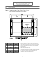
UNITY/I
™
Three-Phase Uninterruptible Power Systems
UT340, UT360, UT380, UT3100
60 Hz
Planning and
Installation Manual
LTM-0357A
Copyright 1995, Best Power Technology, Inc.
UT340, UT360, UT380, and UT3100
Planning and Installation Manual
IMPORTANT SAFETY INSTRUCTIONS
SAVE THESE INSTRUCTIONS
This manual contains important instructions for your UNITY/I™ UPS.
The installation and use of this product must comply with all national, federal, state, municipal,
or local codes that apply. If you need help, please call BEST’s Technical Support Center at
1-800-356-5737 (U.S.A. or Canada; elsewhere, call your local BEST office).
WARNING!
UPS units contain hazardous AC and DC voltages. A qualified electrician must install the
UPS, AC line service, and external batteries according to local and national codes and must
be familiar with batteries and battery installation.
Before installing, maintaining, or servicing the UPS, shut off the UPS and disconnect all
sources of AC and DC power.
Whenever AC and/or DC voltage is applied, there may be AC voltage at the UPS output;
this is true because the UPS can supply output power from mains or from its batteries. To
avoid equipment damage or personal injury, always assume that there may be voltage at the
UPS output.
TEST BEFORE TOUCHING!
To reduce the risk of fire or electric shock, install the UPS and external batteries in a
temperature and humidity controlled indoor area, free of conductive contaminants.
UPS batteries are high current sources. Shorting battery terminals or DC terminal strips can
cause severe arcing, equipment damage and injury. A short circuit can cause a battery to
explode. Always wear protective clothing and eye protection and use insulated tools when
working near batteries.
This unit contains components that are sensitive to electrostatic discharge (ESD).
If you do not follow proper ESD procedures, you may cause severe damage to
electronic components.
UT340, UT360, UT380, and UT3100
Planning and Installation Manual
Table of Contents
List of Tables and Figures . . . . . . . . . . . . . . . . . . . . . . . . . . . . . . . . . . . . . . . . . . . . . . . ii
100:
Introduction . . . . . . . . . . . . . . . . . . . . . . . . . . . . . . . . . . . . . . . . . . . . . . . . . . . . . . . . . . . 1
101: UPS Footprint . . . . . . . . . . . . . . . . . . . . . . . . . . . . . . . . . . . . . . . . . . . . . . . . . . . . . 2
102: Specifications for the UT340 and UT360 . . . . . . . . . . . . . . . . . . . . . . . . . . . . . . . . 3
103: Specifications for the UT380 and UT3100 . . . . . . . . . . . . . . . . . . . . . . . . . . . . . . . 5
104: Receiving and Moving the UPS . . . . . . . . . . . . . . . . . . . . . . . . . . . . . . . . . . . . . . . 7
105: Storing the UPS and Batteries . . . . . . . . . . . . . . . . . . . . . . . . . . . . . . . . . . . . . . . . 8
106: Finding a Location for the UPS . . . . . . . . . . . . . . . . . . . . . . . . . . . . . . . . . . . . . . . 8
107: Technical Support . . . . . . . . . . . . . . . . . . . . . . . . . . . . . . . . . . . . . . . . . . . . . . . . . . 9
200:
Installation . . . . . . . . . . . . . . . . . . . . . . . . . . . . . . . . . . . . . . . . . . . . . . . . . . . . . . . . . . . . 9
201: Installing the Maintenance Bypass Cabinet (MBC) and UPS . . . . . . . . . . . . . . . 10
202: Installing the External Batteries and DC Disconnect (DCD) . . . . . . . . . . . . . . . . 18
300:
Initial Startup and Phase Check . . . . . . . . . . . . . . . . . . . . . . . . . . . . . . . . . . . . . . . . . . 22
301: Initial Startup and Phase Check
for Units with a BEST-Supplied Rotary Switch MBC . . . . . . . . . . . . . . . . . . . . . 23
302: Initial Startup and Phase Check
for Units with a BEST-Supplied Three-Breaker MBC . . . . . . . . . . . . . . . . . . . . . 26
400:
Clearing the Events Log . . . . . . . . . . . . . . . . . . . . . . . . . . . . . . . . . . . . . . . . . . . . . . . . 29
500:
Shutdown Procedures . . . . . . . . . . . . . . . . . . . . . . . . . . . . . . . . . . . . . . . . . . . . . . . . . . 29
501: Shutdown Procedure for Units with a BEST-Supplied Rotary Switch MBC . . . . 30
502: Shutdown Procedure for Units with a BEST-Supplied Three-Breaker MBC . . . 30
600:
Startup from Maintenance Bypass . . . . . . . . . . . . . . . . . . . . . . . . . . . . . . . . . . . . . . . . 31
601: Startup from Maintenance Bypass with a BEST-Supplied Rotary Switch MBC . 31
602: Startup from Maintenance Bypass with a BEST-Supplied Three-Breaker MBC . 32
700:
Glossary of Terms and Abbreviations . . . . . . . . . . . . . . . . . . . . . . . . . . . . . . . . . . . . . . 33
701: Glossary of Terms . . . . . . . . . . . . . . . . . . . . . . . . . . . . . . . . . . . . . . . . . . . . . . . . . 33
702: Abbreviations . . . . . . . . . . . . . . . . . . . . . . . . . . . . . . . . . . . . . . . . . . . . . . . . . . . . 34
i
UT340, UT360, UT380, and UT3100
Planning and Installation Manual
List of Tables and Figures
Tables
1
2
3
4
5
6
7
8
AC Input Specifications, UT340 and UT360 . . . . . . . . . . . . . . . . . . . . . . . . . . . . . . . . . . . . . 3
AC Output Specifications, UT340 and UT360 . . . . . . . . . . . . . . . . . . . . . . . . . . . . . . . . . . . 3
DC Input/Battery Specifications, UT340 and UT360 . . . . . . . . . . . . . . . . . . . . . . . . . . . . . . 4
General Specifications, UT340 and UT360 . . . . . . . . . . . . . . . . . . . . . . . . . . . . . . . . . . . . . . 4
AC Input Specifications, UT380 and UT3100 . . . . . . . . . . . . . . . . . . . . . . . . . . . . . . . . . . . . 5
AC Output Specifications, UT380 and UT3100 . . . . . . . . . . . . . . . . . . . . . . . . . . . . . . . . . . 5
DC Input/Battery Specifications, UT380 and UT3100 . . . . . . . . . . . . . . . . . . . . . . . . . . . . . 6
General Specifications, UT380 and UT3100 . . . . . . . . . . . . . . . . . . . . . . . . . . . . . . . . . . . . . 6
Figures
1
2
3
4
5
6
7
8
Footprint of the UT340, UT360, UT380, UT3100
with Conduit Connection Kit (Top View) . . . . . . . . . . . . . . . . . . . . . . . . . . . . . . . . . . . 2
Front View (Covers Removed) . . . . . . . . . . . . . . . . . . . . . . . . . . . . . . . . . . . . . . . . . . . . . . 11
UT340 - UT3100 Installation Wiring Diagram,
Typical Installation With No Maintenance Bypass Cabinet . . . . . . . . . . . . . . . . . . . . . 12
UT340 and UT360 Installation Wiring Diagram, Typical Installation . . . . . . . . . . . . . . . . 13
UT380 and UT3100 Installation Wiring Diagram, Typical Installation . . . . . . . . . . . . . . . 14
External Connection Board . . . . . . . . . . . . . . . . . . . . . . . . . . . . . . . . . . . . . . . . . . . . . . . . . 15
Communication Interface Board (Option) . . . . . . . . . . . . . . . . . . . . . . . . . . . . . . . . . . . . . . 16
Relay Board (Option) . . . . . . . . . . . . . . . . . . . . . . . . . . . . . . . . . . . . . . . . . . . . . . . . . . . . . . 17
ii
UT340, UT360, UT380, and UT3100
Planning and Installation Manual
Section 100: Introduction
An uninterruptible power system (UPS) protects sensitive equipment against unacceptable
disturbances from the mains (AC line) supply. The UNITY/I™ three-phase UPS has the capacity
to serve a wide variety of electrical equipment— from mainframe computers to enterprise-wide
EDP installations to production lines. The UNITY/I three-phase UPS provides true on-line,
single-conversion technology and harmonics isolation.
Only a qualified electrician should install this unit. The planning and installation manual gives
the electrician guidelines for:
installation wiring.
external battery installation.
UPS startup procedures.
phase check for the maintenance bypass cabinet (MBC).
UPS shutdown procedures.
If you need assistance, please have the UPS model number and serial number available and call
BEST’s Technical Support Center at 1-800-356-5737 (U.S.A. or Canada) or call your local
BEST office.
1
UT340, UT360, UT380, and UT3100
Planning and Installation Manual
101
UPS Footprint
Figure 1: Footprint of the UT340, UT360, UT380, UT3100
with Conduit Connection Kit (Top View)
CONDUIT
CONNECTION
BOX
CABLE ENTRY
Inches
Millimeters
A
39.4
1000
B
17.9
455
Allow a minimum of 3 feet (914 mm) at the front of the
unit, 3 feet (914 mm) at the top of the unit, and 6 inches
(152 mm) at the back of the unit for service clearance
and for air flow.
C
19.8
504
Cable entry from bottom only.
D
27.9
708
E
31.7
804
F
2.4
60
The conduit connection kit includes a conduit connection
box and three pedestals, shipped separately. See
installation instructions shipped with kit.
2
UT340, UT360, UT380, and UT3100
Planning and Installation Manual
102
Specifications for the UT340 and UT360
Tables 1 - 4 contain specifications for UPS models UT340 and UT360.
Table 1: AC Input Specifications, UT340 and UT360
UT340
Voltage
Rated input current - Amps
Mains tolerance % (programmable)
Bypass tolerance % (programmable)
Frequency - Hz
Current distortion % - THD
Acceptable cable size range - AWG 1, 2, 3
Recommended overcurrent protection Amps 3, 4
UT360
3 x 208Y/120
146
3 x 480Y/277
63
3 x 208Y/120
219
3 x 480Y/277
95
+10, -15
±10
+10, -15
±10
+10, -15
±10
+10, -15
±10
60 ±6%
0-5
3/0 - 250 kcmil
200
60 ±6%
0-5
4-2
80
60 ±6%
0-5
300 - 500 kcmil
300
60 ±6%
0-5
1 - 2/0
125
Table 2: AC Output Specifications, UT340 and UT360
UT340
UT360
Voltage
Rated output current - Amps
Tolerance % - symmetrical load
- asymmetrical load 5
- load step 0-100%
Distortion % - linear load
Frequency - Hz
- mains synchronized
- free running %
Overload capacity %, mains operation
- 1 minute
- 10 minutes
Overload capacity %, battery operation
- 1 minute
- 10 minutes
Acceptable cable size range - AWG 1, 2, 3
208Y/120
111
±1
±3
±5
0-3
480Y/277
48
±1
±3
±5
0-3
208Y/120
167
±1
±3
±5
0-3
480Y/277
72
±1
±3
±5
0-3
60 ±6%
±0.1
60 ±6%
±0.1
60 ±6%
±0.1
60 ±6%
±0.1
250
150
250
150
250
150
250
150
150
125
150
125
150
125
150
125
1/0 - 3/0
6-3
4/0 - 300 kcmil
3-1
Recommended overcurrent protection Amps 3, 4
150
60
225
90
Notes for Tables 1 and 2:
1 Based upon UL rating of termination connector and upon 75oC copper conductors at 30o C ambient from NEC Table 310-16.
Conductor size may vary based on installation requirements.
2 For a 100% switch mode load, it is recommended that you size the neutral conductor for 1.732 times the phase current.
3 For units with external bypass, see Figures 4 and 5.
4 For UPS module only (UPS input breaker).
5 100% imbalance, provided output current rating is not exceeded.
3
UT340, UT360, UT380, and UT3100
Planning and Installation Manual
Table 3: DC Input/Battery Specifications, UT340 and UT360
UT340
UT360
250 kcmil or 2 x 1/0
500 kcmil or 2 x 3/0
Nominal DC current - Amps
200
300
Nominal DC voltage
216
216
Nominal number of cells
108
108
246
246
20
30
91
91
89
86
92
92
90
87
Acceptable external battery cable size range AWG 1
Factory-set float charge voltage 2
Charger current limit - Amps
Inverter % efficiency
3
- 100% load
- 75% load
- 50% load
- 25% load
Notes for Table 3:
o
o
1 Based on 75 C copper conductors at 30 C ambient, intermittent duty, from NEC Table 310-16. Conductor size may vary
based on installation requirements.
2 Adjust the float charge voltage setting per the battery manufacturer’s recommendations.
3 Programmable to lower level.
Table 4: General Specifications, UT340 and UT360
UT340
UT360
60
120
60
120
2.11 (7185)
1.67 (5688)
1.68 (5748)
1.33 (4551)
3.16 (10,778)
1.86 (6333)
2.53 (8622)
1.48 (5067)
95
96
95
97
95
95
32 - 104 (0 - 40)
32 - 104 (0 - 40)
77 (25)
77 (25)
706.8 (1200)
706.8 (1200)
55
55
59.1 x 39.4 x 31.5
(1500 x 1000 x 800)
59.1 x 39.4 x 31.5
(1500 x 1000 x 800)
UPS total weight - lbs (kg)
1741 (790)
2160 (980)
Conduit connection kit weight - lbs (kg)
54 (24.49)
54 (24.49)
14.93 (102.94)
18.42 (127)
Noise attenuation - dB
- differential mode
- common mode 1
Typical heat dissipation - kW (BTU)
- At full rated load, normal operation
- At full rated load, economy mode
- At 0.8 PF load, normal operation
- At 0.8 PF load, economy mode
Efficiency %, AC to AC
- normal operation
- economy mode
Humidity %, non-condensing maximum
Ambient UPS and battery temperature - F ( C)
o
o
Ideal UPS and battery temperature - F ( C)
o
o
Air flow - CFM (m3/hour)
Audible noise, typical - dBa
UPS dimensions, with conduit connection kit
H x W x D - inches (mm)
Floor loading, UPS with conduit connection kit pounds per square inch (kPa)
Note for Table 4:
1 With isolation transformer and the UPS wired as a separately derived system.
4
UT340, UT360, UT380, and UT3100
Planning and Installation Manual
103
Specifications for the UT380 and UT3100
Tables 5 - 8 contain specifications for UPS models UT380 and UT3100.
Table 5: AC Input Specifications, UT380 and UT3100
UT380
UT3100
3 x 480Y/277
3 x 480Y/277
127
159
Mains tolerance % (programmable)
+10, -15
+10, -15
Bypass tolerance % (programmable)
±10
±10
60 ±6%
60 ±6%
0-5
0-5
2/0 - 4/0
3/0 - 250 kcmil
175
200
UT380
UT3100
480Y/277
480Y/277
96
120
±1
±3
±5
±1
±3
±5
0-3
0-3
60 ±6%
±0.1
60 ±6%
±0.1
- 1 minute
- 10 minutes
250
150
250
150
Overload capacity % battery operation - 1 minute
- 10 minutes
150
125
150
125
1 - 2/0
1/0 - 3/0
125
150
Voltage
Rated input current - Amps
Frequency - Hz
Current distortion % - THD
Acceptable cable size range - AWG
1, 2, 3, 4, 5
Recommended overcurrent protection - Amps 4, 5
Table 6: AC Output Specifications, UT380 and UT3100
Voltage
Rated output current - Amps
Tolerance %
- symmetrical load
- asymmetrical load 6
- load step 0-100%
Distortion %, linear load
Frequency - Hz
- mains synchronized
- free running %
Overload capacity % mains operation
Acceptable cable size range - AWG 1, 2, 3, 4, 5
Recommended overcurrent protection - Amps 4, 5
Notes for Tables 5 and 6:
1 Bus bar can accept up to 2 cables per terminal.
2 Based upon UL rating of termination connector and upon 75o C copper conductors at 30o C ambient from NEC Table 310-16.
Conductor size may vary based on installation requirements.
3 For a 100% switch mode load, it is recommended that you size the neutral cable for 1.732 times the phase current.
4 For units with external bypass, see Figures 4 and 5.
5 For UPS module only (UPS input breaker).
6 100% imbalance, provided output current rating is not exceeded.
5
UT340, UT360, UT380, and UT3100
Planning and Installation Manual
Table 7: DC Input/Battery Specifications, UT380 and UT3100
UT380
UT3100
250 kcmil or 2 x 1/0
500 kcmil or 2 x 3/0
Nominal DC current - Amps
245
310
Nominal DC voltage
360
360
180
180
410
410
25
30
92
92
90
87
93
93
91
88
Acceptable external battery cable size range - AWG
1
Nominal number of cells
Factory-set float charge voltage
2
Charger current limit - Amps 3
Inverter % efficiency
- 100% load
- 75% load
- 50% load
- 25% load
Notes for Table 7:
1 Based on 75o C copper conductors at 30o C ambient, intermittent duty, from NEC Table 310-16. Conductor size may vary
based on installation requirements.
2 Adjust the float charge voltage setting per the battery manufacturer’s recommendations.
3 Programmable to lower level.
Table 8: General Specifications, UT380 and UT3100
UT380
UT3100
60
120
60
120
3.33 (11,377)
2.47 (8445)
2.67 (9101)
1.98 (6756)
4.17 (14,221)
3.09 (10,556)
3.33 (11,377)
2.47 (8445)
96
97
96
97
95
95
32 - 104 (0 - 40)
32 - 104 (0 - 40)
77 (25)
77 (25)
706.8 (1200)
706.8 (1200)
55
55
59.1 x 39.4 x 31.5
(1500 x 1000 x 800)
59.1 x 39.4 x 31.5
(1500 x 1000 x 800)
2425 (1100)
2634 (1195)
Conduit connection kit weight - lbs (kg)
54 (24.49)
54 (24.49)
UPS weight with conduit connection kit pounds per square inch (kPa)
20.62 (142.17)
22.36 (154.17)
Noise attenuation - dB
- differential mode
- common mode 1
Typical heat dissipation - kW (BTU)
- At full rated kW load, normal operation
- At full rated kW load, economy mode
- At 0.8 PF load, normal operation
- At 0.8 PF load, economy mode
Efficiency %, AC to AC
- normal operation
- economy mode
Humidity %, non-condensing maximum
Ambient UPS and battery temperature - o F (o C)
Ideal UPS and battery temperature - F ( C)
o
o
Air flow - CFM (m3/hour)
Audible noise, typical - dBa
UPS dimensions, with conduit connection kit
H x W x D - inches (mm)
UPS total weight - lbs (kg)
1 With isolation transformer and the UPS wired as a separately derived system.
6
UT340, UT360, UT380, and UT3100
Planning and Installation Manual
104
Receiving and Moving the UPS
WARNING!
The UPS and related equipment are very heavy. To prevent personal injury or equipment
damage, use extreme care when handling and transporting the UPS cabinet and related
equipment.
1.
While the UPS system is still on the truck, inspect the equipment and shipping container(s)
for any signs of damage. Do not install the system if damage is apparent. If damage has
occurred, notify BEST as soon as possible.
2.
Compare the shipment with the bill of lading. Report any missing items to the carrier and to
BEST immediately.
3.
Remove the screws on the bottom part of the packaging side plates.
4.
Lift the main package up and off the unit and remove the packing materials from the unit.
5.
Check that the label inside the UPS front door corresponds to the system ordered, especially
the input/output voltages.
6.
Unbolt the unit from the pallet.
7.
Remove the unit from the pallet with a fork lift.
8.
Use a fork lift or hand truck to transport the unit to the installation site or storage site. Study
the footprint to decide how you will move the UPS through doorways and into position.
9.
Install the separately shipped conduit connection kit. See the conduit connection kit for
installation instructions.
7
UT340, UT360, UT380, and UT3100
Planning and Installation Manual
105
Storing the UPS and Batteries
You can store the UNITY/I UPS between -4o and 104o F (-20o and 40o C). However, BEST
recommends that the unit and batteries be stored between 59o and 77o F (15o and 25o C). This
temperature range or cooler allows batteries to have a longer shelf life. Recharge stored batteries
every 90 to 120 days.
106
Finding a Location for the UPS
Keep these guidelines in mind when you choose the location for the UPS system and the
batteries.
Place the UPS in a clean, dust-free environment, free of contaminants. The air must be free
to circulate around the UPS cabinet and any battery cabinets or racks.
Avoid placing the unit in direct sunlight or near other heat sources.
Make sure that the ambient temperature is 32o to 104o F (0o to 40o C).
Ideal temperature is 77o F (25o C).
NOTE: At 95o F (35o C), battery life will be about one-half of what it would be at a normal
temperature of 77o F (25o C). At 113o F (45o C), battery life will be about onefourth of normal.
Make sure that the floor can support the weight of the UPS, external batteries, and any other
necessary equipment. See Table 4 in Section 102 or Table 8 in Section 103 for weights and
floor loading specifications.
The unit can be placed close to walls as long as there is enough clearance for the front doors
to open. Required service clearance is 3 feet (914 mm) at the front and 3 feet (914 mm) at
the top of the unit. If possible, allow a minimum of 3 feet (914 mm) of clearance around the
entire unit for easier servicing.
All service access is from the front and top of the unit. Cable entry is from the bottom of the
unit.
Do not operate the UPS or batteries in a sealed room or container.
8
UT340, UT360, UT380, and UT3100
Planning and Installation Manual
107
Technical Support
Best Power Technology, Incorporated is committed to outstanding customer service. Our
Technical Support Center is happy to help you with any problems or answer any questions you
may have. A service technician is available 24 hours a day, 365 days a year.
Please have the UPS model number and serial number available when you call. See the ID
label located inside the front door of the UPS.
Technical Support:
1-800-356-5737 (U.S.A. and Canada) or 1-608-565-2100
Technical Support Fax:
1-608-565-7642 or 1-608-565-2509
Bulletin Board Service:
1-608-565-7424
CompuServ:
Type “Go BEST” at any ! prompt
Section 200: Installation
WARNING!
Before continuing, read the warnings on the inside front cover of this manual.
Insulated Tools and Other Equipment Needed:
Torque wrench in inch-pounds or
newton-meters
Standard U.S. and metric wrenches
Petroleum jelly or conductive grease
Mallet
Volt-Ohm meter (True RMS - Digital)
Pliers
Ratchet and sockets
Electrical tape
Standard and Phillips screwdrivers
Torx head screwdriver set
Brush (for applying petroleum jelly or
conductive grease to battery terminals)
UNITY/I User Manual
Phase rotation meter
The customer must provide all cabling and interconnection hardware.
9
UT340, UT360, UT380, and UT3100
Planning and Installation Manual
201
Installing the Maintenance Bypass Cabinet (MBC) and UPS
IMPORTANT!
If you do not have a BEST maintenance bypass cabinet (MBC), you must provide
overcurrent protection and a UPS input AC disconnect means.
BEST strongly recommends that a means of bypassing the UPS from the critical load be
provided for maintenance.
Follow these guidelines when installing the MBC and UPS:
Use the information in Section 106 to find an appropriate location for the UPS. Install the
conduit connection kit per the instructions provided with the conduit connection kit.
Install the MBC within sight of the UPS. When installing the MBC, see Figure 4 or 5 and
any instructions provided with the MBC.
Install the AC input and UPS output in separate conduits. UPS output cabling shall be
installed in dedicated conduit systems and not shared with other electrical circuits.
Control wiring must be installed in separate conduit.
Good ground connections are necessary to reduce electrical noise and make the operation of
the UPS and the loads safe. Follow the grounding guidelines in the installation wiring
diagram. Refer to the National Electrical Code (NEC), appropriate IEEE documents, and all
applicable codes.
When installing the AC wiring, refer to Figure 3, 4, or 5 and to any additional diagrams
provided with the UPS.
Figures 3, 4, and 5 show typical installations. Your installation may differ.
• If you are installing the UPS with no maintenance bypass cabinet, see Figure 3.
• If you have a UT340 or UT360 with a BEST-supplied rotary switch MBC, see Figure 4.
• If you have a UT380 or UT3100 with a BEST-supplied three-breaker MBC, see Figure 5.
See Figure 2 for a front view of the UPS with the covers removed. See Figure 6 for
information on the external connection board. See Figure 7 for information on the optional
communication interface board. See Figure 8 for information on the optional relay board.
If you have any questions, contact BEST’s Technical Support Center for assistance (see
Section 107).
10
UT340, UT360, UT380, and UT3100
Planning and Installation Manual
Figure 2: Front View (Covers Removed)
11
UT340, UT360, UT380, and UT3100
Planning and Installation Manual
Figure 3:
UT340 - UT3100 Installation Wiring Diagram, Typical Installation,
No External Maintenance Bypass Cabinet
ADDITIONAL NOTES:
A qualified electrician must install the UPS according
to all applicable codes.
All power and control wires must be in separate
conduits.
The grounding electrode conductor (protective
earth—PE) must be the same size (ampacity) as the
UPS input conductors. Conduit is not an acceptable
grounding electrode conductor—see National Electrical
Code Section 250-91(a).
A UT340 or UT360 unit is wired from the factory as a
separately derived system. Output neutral is bonded to
equipment ground through main bonding jumper inside
the UPS. See National Electrical Code Article 250-5(d)
and 250-26 for proper installation grounding.
NOTE 1: (a) For a UT340 or UT360, see Table 1 in
Section 102 for recommended input overcurrent
protection. (b) For a UT380 or UT3100, see Table 5 in
Section 103 for recommended input overcurrent
protection.
NOTE 2: (a) For a UT340 or UT360, see Table 2 in
Section 102 for recommended output overcurrent
protection. (b) For a UT380 or UT3100, see Table 6 in
Section 103 for recommended output overcurrent
protection.
NOTE 3: You must provide overcurrent protection and
UPS input AC disconnect means.
NOTE 4: (a) Refer to any instructions provided with the
DC disconnect (DCD) and pre-charge/discharge switch.
(b) The pre-charge/discharge box must be located less
than 10 feet (3 m) from the DC disconnect.
12
UT340, UT360, UT380, and UT3100
Planning and Installation Manual
Figure 4: UT340 and UT360 Installation Wiring Diagram, Typical Installation
ADDITIONAL NOTES:
A qualified electrician must install the UPS according
to all applicable codes.
All power and control wires must be in separate
conduits.
The grounding electrode conductor (protective
earth—PE) must be the same size (ampacity) as the
UPS input circuit conductors. Conduit is not an
acceptable grounding electrode conductor—see
National Electrical Code Section 250-91(a).
A UT340 or UT360 unit is wired from the factory as a
separately derived system. Output neutral is bonded to
equipment ground through main bonding jumper inside
the UPS. See National Electrical Code Article 250-5(d)
and 250-26 for proper installation grounding.
If you do not have a BEST-supplied maintenance
bypass cabinet (MBC), you must provide overcurrent
protection and UPS input AC disconnect means.
The maintenance bypass switch must be a 4-pole
device which switches all three phases and neutral. If
you are using a 3-pole device, contact BEST’s
Technical Support Center for instructions to convert the
unit to a not-separately derived system.
NOTE 1: Size the mains input overcurrent protection
device per applicable codes. See the table below for
mains input voltage and current ratings.
Mains Input
UPS Model
VAC
Maximum Amps
UT340
208
200
UT340
480
86
UT360
208
301
UT360
480
130
NOTE 2: (a) Refer to any instructions provided with the
DC disconnect (DCD) and pre-charge/discharge box.
(b) The pre-charge/discharge box must be located less
than 10 feet (3 meters) from the DC disconnect.
13
UT340, UT360, UT380, and UT3100
Planning and Installation Manual
Figure 5: UT380 and UT3100 Installation Wiring Diagram, Typical Installation
ADDITIONAL NOTES:
A qualified electrician must install the UPS according
to all applicable codes.
All power and control wires must be in separate
conduits.
If you do not have a BEST-supplied maintenance
bypass cabinet (MBC), you must provide overcurrent
protection and UPS input AC disconnect means.
NOTE 1: Size the mains input overcurrent protection
device per applicable codes. See the table below for
mains input voltage and current ratings.
Mains Input
UPS Model
VAC
Maximum Amps
UT380
480
173
UT3100
480
216
NOTE 2: (a) Refer to any instructions provided with the
DC disconnect (DCD) and pre-charge/discharge box.
(b) The pre-charge/discharge box must be located less
than 10 feet (3 meters) from the DC disconnect.
14
UT340, UT360, UT380, and UT3100
Planning and Installation Manual
Figure 6: External Connection Board
Use Class 1 wiring methods.
1
NOT USED
X001
NOT USED
X002
NOT USED
X005
NOT USED
3
1
NOT USED
X006
3
1
SUMMARY ALARM IF 1-3 CONNECTED
2
X007
3
1
BATTERY OPERATION (30 SECS. DELAY)
BATTERY OPERATION IF 1-3 ARE CONNECTED
2
X008
3
1
EXTERNAL BYPASS CONTACT
1-3 CONNECTED IF SYSTEM IS
IN STATIC BYPASS OPERATION
2
X009
3
1
2
NOT USED
X010
3
1
MBC INHIBIT; IF SYSTEM OUTPUT IS OUTSIDE LIMITS
THEN 1-3 ARE CONECTED
2
1
2
NOT USED
POSITION INDICATOR OF DCD IN OPTIONAL BATT. CABINET
A JUMPER MUST BE USED IF THE UNIT HAS INTERNAL BATTERIES
BATTERY TEMPERATURE COMPENSATION PROBE
X011
3
3
110
BROWN
BLUE
4
X003
5
TO CONTROLLER
BOARD
6
7
POSITION INDICATOR OF EXTERNAL UPS BYPASS SWITCH
8
9
10
NOT USED
X012
11
REMOTE START/STOP
13 COMMON, 11 "ON", 12 "OFF" (CLOSING CONTACTS)
12
13
EMERGENCY SHUT DOWN IF 12VDC (10mA) EXTERNAL SUPPLY
IS REMOVED FROM TERMINALS. TO USE THIS FUNCTION
REMOVE JUMPER SWO1
SW01
14
15
16
EMERGENCY SHUT DOWN IF DISCONNECTED (12V CIRCUIT)
111
X004
17
X007-X011 ARE CHANGE OVER RELAY CONTACTS (NOT TO EXCEED NEC ART. 725 C CLASS 2 LIMITS)
15
NOT USED
UT340, UT360, UT380, and UT3100
Planning and Installation Manual
Figure 7: Communication Interface Board (Option)
Use Class 1 wiring methods.
Not Used
To Controller
X002
X001
X003 25 PIN SUB D MALE
X004 25 PIN SUB D MALE
X005 25 PIN SUB D FEMALE
COMMUNICATION
INTERFACE BOARD
X005
X004
X003
Serial Port
RS232
Serial Port
0 - 20 mA current loop
RELAY CONTACTS: 30 VAC, 60 VDC
Maximum 0.5 A, Minimum 0.05 mA
COM-PORT
14
15
2
“UPS on” (shown with UPS off)
16
17
4
“Static bypass operation” (shown with static bypass operation off)
18
19
6
“Battery operation” (shown with battery operation off)
20
21
8
“Battery low warning” (shown with “battery low” warning off)
13 +
25 –
Remote UPS shut down input (3.5 - 25 VDC pulse for 1 second minimum)
16
UT340, UT360, UT380, and UT3100
Planning and Installation Manual
Figure 8: Relay Board (Option)
The relays are shown in the alarm position and correspond to non-energized coils.
RELAY
BOARD
X002:1
2
3
MAINS FAILURE
X003:1
2
3
BATTERY CHARGING FAILURE
X004:1
2
3
OVERLOAD
Description
Minimum
Maximum
Contact voltage - AC
6V
250 V
Contact current - AC *
50 mA
8A
6 V / 50 mA
250 V / 0.3 A
6V/8A
Contact voltage and
current - DC *
* Resistive load
X005:1
2
3
FAN FAILURE
X006:1
2
3
INVERTER FUSE FAILURE
X007:1
2
3
LOW BATT. VOLTAGE
X008:1
2
3
HIGH TEMPERATURE
X009:1
2
3
BATTERY DCD OFF
X010:1
2
3
OUTPUT VOLTAGE
OUTSIDE LIMITS
X011:1
2
3
UPS ON STATIC BYPASS
X012:1
2
3
EXTERNAL MANUAL BYPASS ON
X013:1
2
3
NORMAL OPERATION
X014:1
2
3
COMMON FAULT
X015:1
2
3
BYPASS VOLTAGE
OUTSIDE LIMITS
X016:1
2
3
BATTERY OPERATION
X017:1
2
3
NOT USED
17
UT340, UT360, UT380, and UT3100
Planning and Installation Manual
202
Installing the External Batteries and DC Disconnect (DCD)
External batteries must be installed and connected to the UPS by a qualified service person who
is familiar with UPS battery installations and applicable building and electrical codes. The
qualified service person should read this entire section before the UPS and batteries arrive.
DANGER!
Full voltage and current are always present at the battery terminals. The batteries used in this
system can produce dangerous voltages, extremely high currents, and a risk of electric shock.
They may cause severe injury if the terminals are shorted together or to ground (earth). You
must be extremely careful to avoid electric shock and burns caused by contacting battery
terminals or shorting terminals during battery installation. Do not touch uninsulated battery
terminals.
A qualified service person who is familiar with battery systems and required precautions
must install and service the batteries. The installation must conform to national and local
codes. Keep unauthorized personnel away from batteries.
The qualified service person must take these precautions:
1.
Wear protective clothing, such as rubber gloves and boots and protective eye wear.
Batteries contain caustic acids and toxic materials and can rupture or leak if mistreated.
Remove rings and metal wristwatches or other metal objects and jewelry. Do not carry
metal objects in your pockets where the objects can fall into the battery cabinet.
2.
Tools must have insulated handles and must be insulated so that they will not short
battery terminals. Do not allow a tool to short between individual or separate battery
terminals or to the cabinet or rack. Do not lay tools or metal parts on top of the batteries,
and do not lay them where they could fall onto the batteries or into the cabinet.
3.
Install the batteries as shown on the drawing provided with the batteries. When
connecting cables, never allow a cable to short across a battery’s terminals, the string of
batteries, or to the cabinet or rack.
4.
Align the cables on the battery terminals so that the cable lug will not contact any part of
the cabinet or rack, even if the battery is moved. Keep the cable away from any sharp
metal edges.
5.
Install the battery cables so they cannot be pinched by the UPS or battery cabinet doors.
18
UT340, UT360, UT380, and UT3100
Planning and Installation Manual
DANGER!
6.
Do not connect the battery terminal to ground (earth). If any battery terminal is
inadvertently grounded, remove the source of the ground. Contacting any part of a
grounded battery can cause a risk of electric shock.
7.
To reduce the risk of fire or electric shock, install the batteries in a temperature and
humidity controlled indoor area, free of contaminants.
8.
Battery system chassis ground (earth) must be connected to the UPS chassis ground
(earth). If you use conduit, this ground conductor must be routed in the same conduit as
the battery conductors.
9.
Where conductors may be exposed to physical damage, protect the conductors in
accordance with all applicable codes.
10. If you are replacing batteries or repairing battery connections, shut off the UPS and
remove both AC and DC power.
Follow these guidelines when installing the batteries:
Refer to any instructions provided with the batteries.
Refer to any instructions provided with the DC disconnect (DCD) and pre-charge/discharge
switch.
External batteries require a fused disconnect or a DC circuit breaker. There should be a
disconnecting means for each battery string. The external battery fuse protects the battery
cables. Size the cables based on the overcurrent protection device.
The battery cables must be sized for a total maximum voltage drop of 2.0 VDC at the rated
DC current.
Wherever conductors may be exposed to physical damage, protect the conductors in
accordance with any applicable codes. This includes battery cables between the UPS and the
battery system and cables between battery cabinets or racks.
BEST recommends routing battery cables through flexible conduit. Install flexible conduit
for battery cables according to local or national code.
The battery system ground (earth) must be connected to the UPS chassis ground (earth). This
ground conductor must be routed with the battery cables.
19
UT340, UT360, UT380, and UT3100
Planning and Installation Manual
Clean the cables and battery terminals before making the battery connections. Apply a thin
coating of conductive grease before making the battery connections, or apply petroleum jelly
to the entire connection after it has been made.
Torque battery connections to the battery manufacturer’s specifications.
Follow the steps below and any instructions provided with the battery system:
1.
2.
Connect the cables between batteries.
a.
In each battery string, connect the cables between batteries as shown in the battery
installation diagram provided with the batteries.
b.
Meter the positive (+) and negative (–) terminal on each battery string to verify proper
nominal voltage and polarity.
Connect the battery cables between battery strings.
a.
Connect the negative () cables between battery strings as shown in the battery
installation diagram provided with the batteries.
b.
Meter the DC voltage between the positive terminals of the strings. The voltage should
measure less than 5 volts. If it measures greater than 5 volts, correct any wiring errors
before you continue.
c.
Connect the positive (+) cables between battery strings as shown in the battery
installation diagram provided with the batteries.
3.
Install the DC disconnect (DCD) and pre-charge/discharge switch. Refer to Figure 3, 4 or 5
and to any instructions provided with the DCD and pre-charge/discharge switch.
4.
Connect the external batteries to the UPS.
a.
Connect the positive (+) cable(s) to the UPS first. Install ring connectors for 10 mm
bolts as required.
b.
To prevent short circuits, insulate the UPS end of the negative (–) cable(s).
Do not connect the negative (–) cables to the UPS yet.
c.
Connect the positive (+) cable(s) to the battery system and tighten to the proper torque
specifications.
d.
Connect the negative () cable(s) to the battery system and tighten to the proper torque
specifications.
20
UT340, UT360, UT380, and UT3100
Planning and Installation Manual
5.
Check the DC voltage.
a.
Connect the DC fuse(s) as shown in the battery installation diagram provided with the
batteries. Verify proper voltage and polarity at the battery pack. See Table 3 in
Section 102 or Table 7 in Section 103 for nominal DC voltage.
b.
Turn the DC disconnect (DCD) “ON.”
c.
Meter for proper nominal DC voltage at the UPS end of the cables. Make sure the
polarity agrees with the markings on the UPS battery input terminals.
d.
After checking the DC voltage, turn the DC disconnect (DCD) “OFF.”
6.
Connect the negative (–) cable(s) to the UPS. Tighten to the proper torque specifications.
7.
Replace all covers.
8.
Continue with Section 300, “Initial Startup and Phase Check.”
Battery Replacement Information
Only a qualified service person familiar with battery systems should replace batteries. See
Section 500, “Shutdown Procedures,” to bypass and shut down the UPS.
Review all of the warnings at the beginning of Section 202 before replacing the batteries.
Use the Same Number and Type of Battery: To ensure continued superior performance of
your UPS and to maintain proper battery charger operation, you must replace the batteries
with the same number of batteries. The batteries must be the same manufacturer type as the
original batteries and have the same voltage and ampere-hour rating as the original batteries.
Verify that the Battery Terminal is Not Grounded: If any battery terminal is inadvertently
grounded, you must remove the connection from the terminal to ground (earth) before you
service the batteries. Contacting any part of a grounded battery can cause a risk of electric
shock. An electric shock will be less likely if you disconnect the ground connection before
you service the batteries.
Handle Used Batteries with Care: Assume that old batteries are fully charged. Use the
same precautions you would use when handling a new battery. Do not short battery terminals
or the battery string with a cable or tool when you disconnect the batteries.
21
UT340, UT360, UT380, and UT3100
Planning and Installation Manual
Dispose of Batteries Properly: For assistance, call BEST’s Technical Support Center at
1-800-356-5737 (U.S.A. or Canada) or call your local BEST office.
WARNING!
Do not dispose of batteries in a fire because the batteries could explode.
Do not open or mutilate batteries. Released electrolyte is harmful to the skin and eyes
and may be toxic.
Batteries contain lead. Many state and local governments have regulations about
disposing of used batteries. Dispose of batteries properly. For assistance, call BEST’s
Technical Support at 1-800-356-5737 or call your local BEST office.
Section 300: Initial Startup and Phase Check
WARNING!
Some units have been programmed at the factory for “autostart.” If programmed for
“autostart,” the unit will turn on any time mains (AC line) is applied (after a 60-second
delay). For more information or to change this feature, see the user manual.
Before continuing, read the warnings on the inside front cover of this manual.
After installing the unit, use this section to perform the initial startup and the phase check for the
maintenance bypass cabinet (MBC).
The steps in this section are for a unit with a BEST-supplied maintenance bypass cabinet (MBC).
If you have a unit with a BEST-supplied rotary switch MBC, see Section 301.
If you have a unit with a BEST-supplied three-breaker MBC, see Section 302.
22
UT340, UT360, UT380, and UT3100
Planning and Installation Manual
301
Initial Startup and Phase Check
for Units with a BEST-Supplied Rotary Switch MBC
Follow this Procedure Exactly! No Load Should Be Connected!
1.
Make sure that all AC and DC power is off.
2.
Switch the UPS bypass switch to “UPS.”
3.
Make sure that the main circuit breaker in the load panel is off so that the loads cannot
receive power from the UPS.
4.
At the mains AC input panel, switch on the input power to the UPS and maintenance bypass
cabinet (MBC).
5.
Switch the UPS AC disconnect switch “ON.” The UPS display should show System
type xxkVA xxxV, and an audible alarm should sound.
6.
Within 20 seconds, the display should show **Stand-by**.
7.
Turn the pre-charge/discharge switch to the pre-charge position and hold it until the LED
turns off.
8.
Switch the battery DC disconnect (DCD) “ON.”
9.
Check the phase rotation at the service panel and the unit. The unit will not start if the phase
rotation is incorrect. The phase rotation must be A, B, C and clockwise.
10. When the audible alarm stops, push the green “on” button located inside the UPS front door.
The display will show Normal operation load power xx%.
NOTE: One or more alarms may occur. If the alarm(s) persists for more than 20 seconds,
refer to the “Alarms” section of the user manual. If the unit activates a “battery
monitor alarm,” you should set the user parameter “battery monitor reset” to “ON.”
11. If the UPS is connected to a generator, verify that the unit operates properly on generator
power before continuing. If the UPS operates properly on generator power, continue this
procedure. If the UPS does not operate properly on generator power, phone BEST’s
Technical Support Center for assistance.
23
UT340, UT360, UT380, and UT3100
Planning and Installation Manual
CAUTION
Before you switch the UPS bypass switch from “UPS” to “LINE”, use the steps below to
check for correct voltage, phasing, and system operating mode.
12. Program the unit into static bypass operation:
a.
Press
to access the user parameters.
b.
Press the
c.
Press
to turn static bypass operation on. The display should show Bypass
operation.
or
key until the display shows Bypass operation: OFF.
13. At the maintenance bypass cabinet (MBC), make sure the UPS output voltage is
approximately the same as the AC line input voltage (there may be slight differences). Use a
true RMS voltmeter to measure the phase-to-neutral voltage at the MBC AC line input and
the MBC output:
a.
b.
c.
MBC AC Line Input
L1 to neutral_______VAC
L2 to neutral_______VAC
L3 to neutral_______VAC
MBC Output
L1 to neutral_______VAC
L2 to neutral_______VAC
L3 to neutral_______VAC
The voltages in the first column should be similar to the voltages in the second column.
If the voltages are more than 10 volts apart for 208 V nominal or 25 volts apart for
480 V nominal, check the connections and correct any wiring problems before
continuing.
14. At the maintenance bypass cabinet (MBC), make sure the UPS output voltage and the AC
line input voltage are in phase. To do this, measure the AC voltages between the following
points at the MBC AC line input and the MBC output:
MBC AC
Line Input
a. L1 input
b. L2 input
c. L3 input
to
to
to
MBC Output
_______VAC
L1 output
_______VAC
L2 output
_______VAC
L3 output
These readings must not be more than 10 VAC! If they are, call BEST’s Technical
Support Center or your local BEST office.
24
UT340, UT360, UT380, and UT3100
Planning and Installation Manual
15. At the maintenance bypass cabinet (MBC), measure the following:
a.
b.
c.
N input to Ground
N output to Ground
N input to N output
_______VAC
_______VAC
_______VAC
“N input to N output” should not exceed “N input to Ground.” If it does, call BEST’s
Technical Support Center.
16. Check for proper voltages at the bypass switch load output terminals and the load
distribution panel(s).
a.
b.
c.
Bypass Switch Load Output
L1 to neutral_______VAC
L2 to neutral_______VAC
L3 to neutral_______VAC
Load Panel Input
L1 to neutral_______VAC
L2 to neutral_______VAC
L3 to neutral_______VAC
17. Switch the UPS bypass switch to “BYPASS.”
18. Recheck for proper voltages at the bypass switch load output and the load distribution
panel(s).
a.
b.
c.
Bypass Switch Load Output
L1 to neutral_______VAC
L2 to neutral_______VAC
L3 to neutral_______VAC
Load Panel Input
L1 to neutral_______VAC
L2 to neutral_______VAC
L3 to neutral_______VAC
19. Switch the UPS bypass switch to “UPS.”
20. Return the UPS to normal operation mode:
a.
Press
to access the user parameters.
b.
Press the
c.
Press
to turn static bypass operation off. The display should show Normal
operation load power xx%.
or
key until the display shows Bypass operation: ON.
You can now apply loads to the system. As the last step of the installation, BEST recommends
that you clear the events log. See Section 400, “Clearing the Events Log.”.
25
UT340, UT360, UT380, and UT3100
Planning and Installation Manual
302
Initial Startup and Phase Check
for Units with a BEST-Supplied Three-Breaker MBC
Follow this Procedure Exactly! No Load Should Be Connected!
1.
Make sure that all AC and DC power is off.
2.
Switch the maintenance bypass breaker (MBB) “OFF.”
3.
Switch the UPS output breaker (UOB) “OFF.”
4.
At the mains AC input panel, switch on the input power to the UPS and maintenance bypass
cabinet (MBC).
5.
Switch the UPS input breaker (UIB) “ON.” The display should show System type
xxkVA xxxV, and an audible alarm should sound.
6.
Within 20 seconds, the display should show **Stand-by**.
7.
Turn the pre-charge/discharge switch to the pre-charge position and hold it until the LED
turns off.
8.
Switch the battery DC disconnect (DCD) “ON.”
9.
Check the phase rotation at the service panel and the unit. The unit will not start if the phase
rotation is incorrect. The phase rotation must be A, B, C and clockwise.
10. When the audible alarm stops, press the green “on” button located inside the UPS front door.
The UPS display will show Normal operation load power xx%.
NOTE: One or more alarms may occur. If the alarm(s) persists for more than 20 seconds,
refer to the “Alarms” section of the user manual. If the unit activates a “battery
monitor alarm,” you should set the user parameter “battery monitor reset” to “ON.”
11. If the UPS is connected to a generator, verify that the unit operates properly on generator
power before continuing. If the UPS operates properly on generator power, continue this
procedure. If the UPS does not operate properly on generator power, phone BEST’s
Technical Support Center for assistance.
26
UT340, UT360, UT380, and UT3100
Planning and Installation Manual
CAUTION
Before you switch the maintenance bypass breaker (MBB) “ON,” use the steps below to
check for correct voltage, phasing, and system operating mode.
12. Program the unit into static bypass operation:
a.
Press
to access the user parameters.
b.
Press the
c.
Press
to turn static bypass operation on. The display should show Bypass
operation.
or
key until the display shows Bypass operation: OFF.
13. Switch the UPS output breaker (UOB) “ON”.
14. At the maintenance bypass cabinet (MBC), make sure that the UPS output voltage is
approximately the same as the AC line input voltage (there may be slight differences). Use a
true RMS voltmeter to measure the phase-to-neutral voltage at the MBC AC line input and
the MBC output.
a.
b.
c.
MBC AC Line Input
L1 to neutral_______VAC
L2 to neutral_______VAC
L3 to neutral_______VAC
MBC Output
L1 to neutral_______VAC
L2 to neutral_______VAC
L3 to neutral_______VAC
The voltages in the first column should be similar to the voltages in the second column.
If the voltages are more than 10 volts apart for 208V nominal or 25 volts apart for
480 V nominal, check the connections and correct any wiring problems before
continuing.
15. At the maintenance bypass cabinet (MBC), make sure the UPS output voltage and AC line
input voltage are in phase. To do this, measure the AC voltage between the following points
at the MBC AC line input and the MBC output:
MBC AC Line Input
a. L1 input
b. L2 input
c. L3 input
to
to
to
MBC Output
_______VAC
L1 output
_______VAC
L2 output
_______VAC
L3 output
These readings must not be more than 10 VAC! If they are, call BEST’s Technical
Support Center or your local BEST office.
27
UT340, UT360, UT380, and UT3100
Planning and Installation Manual
16. At the maintenance bypass cabinet (MBC), measure the following:
a.
b.
c.
N input to Ground
N output to Ground
N input to N output
______VAC
______VAC
______VAC
“N input to N output” should not exceed “N input to Ground.” If it does, call BEST’s
Technical Support Center.
17. Check for proper voltages at the maintenance bypass cabinet (MBC) load output terminals
and the load distribution panel(s).
a.
b.
c.
MBC Load Output
L1 to neutral______VAC
L2 to neutral______VAC
L3 to neutral______VAC
Load Panel Input
L1 to neutral______VAC
L2 to neutral______VAC
L3 to neutral______VAC
18. Switch the maintenance bypass breaker (MBB) “ON.”
19. Switch the UPS output breaker (UOB) “OFF.”
20. Recheck for proper voltages at the MBC load output terminals and load distribution panel(s).
a.
b.
c.
MBC Load Output
L1 to neutral______VAC
L2 to neutral______VAC
L3 to neutral______VAC
Load Panel Input
L1 to neutral______VAC
L2 to neutral______VAC
L3 to neutral______VAC
21. Switch the UPS output breaker (UOB) “ON.”
22. Switch the maintenance bypass breaker (MBB) “OFF.”
23. Return the UPS to normal operation:
a.
Press
to access the user parameters.
b.
Press the
c.
Press
to turn static bypass operation off. The display should show Normal
operation load power xx%.
or
key until the display shows Bypass operation: ON.
You can now apply loads to the system. As the last step of the installation, BEST recommends
that you clear the events log. See Section 400, “Clearing the Events Log.”
28
UT340, UT360, UT380, and UT3100
Planning and Installation Manual
Section 400: Clearing the Events Log
The events log contains the 250 most recent UPS events, including alarms. To clear the events
log, follow the steps below:
1.
Simultaneously press
and
. The display should show Key in password.
2.
Using the key pad, enter “920701.” The display should show Logging stack is
reset. The events log is now cleared.
3.
Press
. The display should show Normal operation load power xx%.
If the unit will not be used immediately, go to Section 500, “Shutdown Procedures.”
Section 500: Shutdown Procedures
WARNING!
After shutting down the unit, wait at least five minutes before removing any access panels
or covers. Access panels should be removed only by qualified service personnel.
After shutting down the UPS, there may still be high voltage inside the unit.
TEST BEFORE TOUCHING!
Before continuing, read the warnings on the inside front cover of this manual.
This section tells how to shut down the UPS from normal operation mode.
This procedure is for a unit with a BEST-supplied maintenance bypass cabinet (MBC).
If you have a unit with a BEST-supplied rotary switch MBC, see Section 501.
If you have a unit with a BEST-supplied three-breaker MBC, see Section 502.
29
UT340, UT360, UT380, and UT3100
Planning and Installation Manual
501
1.
Shutdown Procedure for Units
with a BEST-Supplied Rotary Switch MBC
If you have shut the loads down: Skip to step 3.
If the loads are to remain powered: Program the unit into static bypass operation:
a.
Press
to access the user parameters.
b.
Press the
c.
Press
to turn static bypass operation on. The display should show Bypass
operation.
or
key until the display shows Bypass operation: OFF.
2.
Switch the UPS bypass switch to “BYPASS.”
3.
Press the red “off” button located inside the UPS front door.
4.
Switch the UPS AC disconnect switch “OFF.”
5.
Switch the DC disconnect (DCD) “OFF.”
6.
Turn the pre-charge/discharge switch to the discharge position and hold it until the LED
turns off. The UPS display should now be blank.
To restart the unit, see Section 601, “Startup from Maintenance Bypass for Units with a
BEST-Supplied Rotary Switch MBC.”
7.
(Optional) If the loads are not to be powered, turn off all AC power sources to the UPS
and maintenance bypass cabinet (MBC).
502
1.
Shutdown Procedure for Units
with a BEST-Supplied Three-Breaker MBC
If you have shut the loads down: Skip to step 4.
If the loads are to remain powered: Program the unit into static bypass operation:
a.
Press
to access the user parameters.
b.
Press the
c.
Press
to turn static bypass operation on. The display should show Bypass
operation.
or
key until the display shows Bypass operation: OFF.
30
UT340, UT360, UT380, and UT3100
Planning and Installation Manual
2.
Switch the maintenance bypass breaker (MBB) “ON.”
3.
Switch the UPS output breaker (UOB) “OFF.”
4.
Press the red “off” button located inside the UPS front door.
5.
Switch the UPS input breaker (UIB) “OFF.”
6.
Switch the DC disconnect (DCD) “OFF.”
7.
Turn the pre-charge/discharge switch to the discharge position and hold it until the LED
turns off. The UPS display should now be blank.
To restart the unit, see Section 602, “Startup from Maintenance Bypass for Units with a
BEST-Supplied Three-Breaker MBC.”
8.
(Optional) If the loads are not to be powered, turn off all AC power sources to the UPS
and maintenance bypass cabinet (MBC).
Section 600: Startup from Maintenance Bypass
This section tells how to start the UPS from maintenance bypass. The steps in this procedure are
for a unit with a BEST-supplied maintenance bypass cabinet (MBC).
If you have a unit with a BEST-supplied rotary switch MBC, see Section 601.
If you have a unit with a BEST-supplied three-breaker MBC, see Section 602.
601
1.
Startup from Maintenance Bypass
for Units with a BEST-Supplied Rotary Switch MBC
Make sure that the following switches are in the following positions:
2.
The UPS AC disconnect switch should be “OFF.”
The UPS bypass switch should be on “LINE.”
The DC disconnect (DCD) should be “OFF.”
Switch the UPS AC disconnect switch “ON.” The UPS display should show System
type xxkVA xxxV and an audible alarm should sound.
31
UT340, UT360, UT380, and UT3100
Planning and Installation Manual
3.
Within 20 seconds, the UPS display should show **Stand-by**.
4.
Turn the pre-charge/discharge switch to the pre-charge position and hold it until the LED
turns off.
5.
Switch the DC disconnect (DCD) “ON.”
6.
Press the green “on” button located inside the front door of the UPS. The UPS display
should show Normal operation load power xx%.
7.
Program the unit into static bypass operation:
a.
Press
to access the user parameters.
b.
Press the
c.
Press
to turn static bypass operation on. The display should show Bypass
operation.
or
key until the display shows Bypass operation: OFF.
8.
Switch the UPS bypass switch to “UPS.”
9.
Program the unit to normal operation:
a.
Press
b.
Press the
c.
Press
to switch the bypass operation off. The display should show Normal
operation load power xx%.
602
1.
to access the user parameters.
or
key until the display shows Bypass operation: ON.
Startup from Maintenance Bypass
for Units with a BEST-Supplied Three-Breaker MBC
Make sure that the following switches are in the following positions:
The UPS input breaker (UIB) should be “OFF.”
The UPS output breaker (UOB) should be “OFF.”
The UPS maintenance bypass breaker (MBB) should be “ON.”
The DC disconnect (DCD) should be “OFF.”
2.
Switch the UPS input breaker (UIB) “ON.” The UPS display should show System type
xxkVA xxxV, and an audible alarm should sound.
3.
Within 20 seconds, the display should show **Stand-by**.
32
UT340, UT360, UT380, and UT3100
Planning and Installation Manual
4.
Turn the pre-charge/discharge switch to the pre-charge position and hold it until the LED
turns off.
5.
Switch the DC disconnect (DCD) “ON.”
6.
Press the green “on” button located inside the UPS front door. The UPS display should show
Normal operation load power xx%.
7.
Program the UPS into static bypass operation:
a.
Press
to access the user parameters.
b.
Press the
c.
Press
to turn bypass operation on. The display should show Bypass
operation.
or
key until the display shows Bypass operation: OFF.
8.
Switch the UPS output breaker (UOB) “ON.”
9.
Switch the maintenance bypass breaker (MBB) “OFF.”
10. Program the unit to normal operation:
a.
Press
to access the user parameters.
b.
Press the
c.
Press
to switch the bypass operation off. The display should show Normal
operation load power xx%.
or
key until the display shows Bypass operation: ON.
Section 700: Glossary of Terms and Abbreviations
See Section 701 for the glossary of terms. See Section 702 for a list of abbreviations.
701
Glossary of Terms
Ampere (Amp): A unit of electric current equivalent to a steady current produced by one volt applied across a
resistance of one ohm.
British thermal unit (BTU): A unit of heat energy equal to the heat needed to raise the temperature of one pound
of air-free water from 60 to 61 F at a constant pressure of one standard atmosphere.
Decibel adjusted (dBa): A unit used to show the relationship between an acoustic noise source and a reference
sound power level of 85 dBm.
33
UT340, UT360, UT380, and UT3100
Planning and Installation Manual
Ground (Earth): A conducting connection, whether intentional or accidental, by which an electric circuit or
equipment is connected to earth or to some conducting body that serves in place of earth.
Load tolerance - symmetrical: Equally balanced loads on a three-phase system.
Load tolerance - asymmetrical: Unbalanced loads on a three-phase system.
Mains: The conductors extending from the service switch, generator bus, or converter bus to the main distribution
center in interior wiring. Synonymous with power source.
Noise attenuation - differential mode: The ability to attenuate noise, line to line.
Noise attenuation - common mode: The ability to attenuate noise, line to ground and neutral to ground.
Nominal voltage: The voltage at which a device operates under ideal conditions.
Power factor (PF): The ratio of the true (real) power to the apparent power: root means-square (RMS) voltage
times RMS current of an alternating current circuit.
Protective earth (PE): Synonymous with grounding electrode conductor.
Static switch: An electronic switch that has no moving parts.
702
Abbreviations
BCA
DCD
MBB
MBC
MIB
MOB
SKRU
UIB
UOB
Battery cabinet assembly
DC disconnect switch (may be a separate switch or a switch located on the battery cabinet/rack)
Maintenance bypass breaker
Maintenance bypass cabinet
Main input breaker
Main output breaker
Solenoid key release unit
UPS input breaker
UPS output breaker
Best Power Technology, Incorporated, reserves the right to change specifications without prior notice.
34