1
ELECTROLUX LIMITED,
LUTON, BEDS. LU4 9QQ
Tel: LUTON 53255
INSTRUCTIONS FOR INSTALLATION OF REFRIGERATOR
MODEL RM12O (BOTTLED GAS AND 12V) IN CARAVANS AND MOBILE HOMES
1., INTRODUCTION
These instructions are important and must be followed closely. Before starting to install the refrigerator, read this leaflet carefully in order
to obtain a thorough understanding of what is required.
When operating, heat is emitted from parts of the cooling unit at the rear and this has to be carried away by air circulating freely over the
back of the refrigerator. To ensure sufficient air circulation for satisfactory operation, it is essential that the clearances called for in this
instruction are not reduced in any way otherwise cooling performance will be impaired and consumption increased. Providing the
°
°
refrigerator is installed in accordance with these instructions, it should operate satisfactorily in ambient temperatures up to 32 C (90 F), with
some measure of cooling in even higher temperatures.
In general, it is recommended that the refrigerator is installed by the caravan manufacturer, the supplier, or another qualified person.
Owners who are competent to carry out the work themselves can do so, but for the sake of safety, they should take particular care in making
the gas connections, checking for leaks, and installing the electrical wiring and fittings. All relevant regulations concerning such installations
must be complied with.
Many caravans are already provided with a recess, usually in the
form of a cupboard which has been specially designed so that it can be
adapted, by removal of its door and shelves, to house a refrigerator.
Some caravan manufacturers have also devised kits of parts to aid
installation of refrigerators in their particular caravans.
A ventilator for fitting above the door as shown in fig. 1 is supplied
with the refrigerator. The connection pipe, gas cock, and connectors are
not supplied by Electrolux as the sizes of these may vary to suit particular
installations. The appropriate parts should, however, be readily available
from the refrigerator supplier or an Agent dealing in gas fittings (see note
in item 13).
The refrigerator weighs approximately 18 kg (40 lbs) and the
surface on which it is installed must be capable of carrying this weight,
plus that of the food, satisfactorily.
All surfaces above and adjacent to the flue outlet, and beside
and below the burner housing, should be of, or covered with, metal or
other non-flammable material.
WARNING
Because of the hazards associated with the use of continuously operating
bottled-gas appliances with open-flame burners in difficult-to-ventilate
confined spaces, and other considerations, Electrolux do not recommend
the installation of their bottled-gas refrigerators on boats, and
refrigerators so installed will not be covered by the Company's guarantee.
If however a boat installation is planned, reference should be made to
British Standard Code of Practice 339 Part 3 (1956) and to Guide Lines published by local water authorities such as Thames Conservancy or the
Ship & Boat Builders' National Federation.
2. VENTILATION
The refrigerator will usually be built into a recess but it can be installed as a free-standing model. Whichever method is used, to enable the
unit to operate efficiently and economically, it is essential that air is allowed to circulate freely over the cooling apparatus at the back to
carry away the heat generated during the cooling process. The minimum free spaces called for under, behind and over the cabinet must
not, therefore, be reduced in any way. The more space provided, particularly behind and over the cabinet, the better the performance you can
expect from the cooling unit.
3. LEVEL
The downward circulation of refrigerant within the cooling unit is by gravity and the refrigerator has to be reasonably level, when it is
°
stationary, for the cooling unit to operate properly. If the refrigerator is left operating with a sustained list in excess of about 3 in any
direction, pockets of liquid refrigerant can collect at various points within the unit impairing or preventing normal circulation of the
refrigerant vapour until level conditions return. It is essential, therefore, that the refrigerator is installed so that the ice-tray shelf inside
the refrigerator is level in relation to the caravan, in both directions, so that when the caravan is level, the ice-tray shelf is level.
With the caravan on tow, the usual rolling and pitching, or long hill climbs, will not normally affect the operation of the cooling unit, but
°
°
when it is stationary a permanent list of more than about 3 in any direction may interfere with its operation. (Note: 3 corresponds to
1
°
about 50 mm at the end of a metre-long plumb line, or 1 /2" at the end of a 30" plumb line). If the list does not exceed 8 , cooling is
°
usually resumed when the refrigerator returns to the upright position, but if it exceeds 8 , the burner should be extinguished or the
electricity supply switched off soon after the list begins otherwise the cooling unit may become damaged due to overheating.
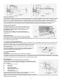
4 . CHANGING DOOR FROM RIGHT TO LEFT HAND OPENING
The refrigerator is manufactured with the door hinged on the right hand side, however, it can be changed to left hand opening if required.
Place the refrigerator on its back (taking care not to damage the burner assembly), pull off the gas thermostat knob, then remove the
lower ventilator by taking out the two screws from each end. Note that the flint lighter will become disengaged.
Transfer the hinge arms and door retainer to the opposite sides. Refit the ventilator, remembering to re-engage the flint lighter, and push
the thermostat knob onto the thermostat spindle so that the flat on the spindle is adjacent to the flat near the centre of the recess in the
knob. Stand the refrigerator on its feet and open the door.
Unscrew the door retaining magnet with its holder from the front of the cabinet lining, prise out the plug sealing the corresponding
1
hole -the opposite side, and screw in the magnet in its place. Fit the plug In the hole originally occupied by the magnet. Transfer the circular
latch plate, with the rubber washers) behind it, to the opposite side of the door. The retaining screw must not be completely tightened; when
correctly positioned, the latch plate must still be comparatively loose on the screw so that it can take up its correct position on the face of the
magnet as the door Is closed.
Adjusting the door seal
Make sure that the latch plate on the door has not been over tightened (see previous paragraph), then screw the magnet on the front of the
cabinet In arils or outwards, half a turn at a time, until a satisfactory door closure and seal is obtained. It is preferable to start with the magnet too
far out, and gradual I, adjust it inwards until satisfactory. It the door seal needs adjusting on the hinge side, this can be done by loosening the
upper and lower hinge arm screws and moving the door inwards
outwards as required. It must not be too tight on the hinge side otherwise the magnet will not be able to pull in the door sufficiently to effect a
good seal,
When correct, the distance between the edge of the door and the front of the cabinet should be the same all round.
Finally, adjust the position of the door retainer on the top corner of the cabinet by loosening its fixing screws and moving it inwards or
outwards so that it Iines up with the hole in the top of the door frame. Tighten the fixing screws when the retainer has been correctly positioned.
5. CHANGING THE OUTER DOOR PANEL
If preferred, the outer door panel can be removed and replaced by one of rust-proofed metal, plastic, or other suitable material with a finish to
match other surfaces in the caravan,
To remove the door panel, take out the screw from each end of the plastic nameplate strip, then pull one end of the strip outwards and
downwards until it is disengaged from the door.
Slide the outer door panel upwards until there is sufficient space to insert the fingers underneath it. Holding the top and bottom edges of
the panel, bow its centre outwards until it can be removed from the aluminium door frame.
Fit the new door panel by locating one side behind the aluminium door frame and bowing out its centre until its other side can be
engaged, Slide the panel down as far as it will go, then refit the nameplate strip by engaging the retaining section of its rear top edge under the
aluminium door frame and sliding it upwards until its lower edge can be located over the top of the door panel. Finally, replace the two screws.
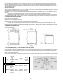
6. DIMENSIONS OF REFRIGERATOR
The exterior dimensions of the refrigerator are given in the following sketches. When installed, the clearances for air circulation given in items 8
and 9 must be allowed for.
7. GAS PRESSURE, BURNER, JET, AND THERMOSTAT BY-PASS SCREW
The burner and burner jet lute fig. 21, and the hexagonal headed brass by-pass screw on the underside of the thermostat body, must all be of the
correct type or size for the gas and gas pressure to be used. The gas pressure is determined by the type of regulator fitted to the gas bottle and
this may vary according to the Standard adopted in the country concerned. In the United Kingdom and in any other parts of Europe, the standard
pressures used for butane and propane are as shown in section 1 of the table below. In Germany and Austria, the higher pressure shown in,
section 2 of the table usually applies.
Before installing the refrigerator, check from the label attached to it that the gas equipment Is correct for the gas and gas pressure to be
used. If it is not, the burner, jet, and thermostat by-pass screw must be changed for the correct type and size in accordance with the table below.
For future reference, any changes made should be recorded on or beside the data label
Type of
Gas
1
*BUTANE
PROPANE
2
PROPANE
Pressure
From
Gas
Bottle
Regulator
(water
gauge)
11”
(280mm)
11” to 14”
(280 to
370mm)
20”
(500mm)
(Usually
Germany
and
Austria)
Size of
Thermostat
By Pass
Screw
Type Of
Burner
Size of
Burner
Jet
With
two
aeration
holes
27
(Part No.
289003909)
14
(Part No.
34191314)
With
one
aeration
hole
23
(Part No.
289003904)
12
(Part No.
34191312)
*eg Calor Gas, Caravangas or Camping Gaz
2
8 . FREE-STANDING INSTALLATIONS
If the refrigerator is to be used as a free-standing model, a vertical free space of at least 75 mm (3") must be left over the top so that
the air circulating over the cooling unit at the back can emerge
unhindered. The flue kit for venting the flue gases to the outside
air must be fitted, - see item 11.
The refrigerator must be secured by some means to prevent
it moving and causing possible damage to the pipe line or its
connections. A suggested method of securing is by means of
metal brackets about 20 mm (%") wide, (which should be made
to suit the particular installation), screwed to the rear top corners
of the refrigerator casing and to the wall of the caravan (fig. 3). It
is not advisable to fix by means of screws or bolts through the
holes in the feet as this could make subsequent removal for
servicing, difficult or time consuming.
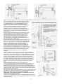
9 . BUILDING-IN
When the refrigerator is built-in, adequate space must be left under, over and behind it to allow a sufficient circulation of air
over the cooling unit at the back for satisfactory operation. The recommended method of building-in is shown in fig. 4, with the upper ventilator at
the front. However, where space limitations do not permit the upper ventilator to be fitted at the front, the alternative arrangements shown in figs.
5 & 6 may be adopted and the height of the recess reduced accordingly. A work-surface can then be fitted over the top front of the refrigerator,
but it must not over-hang the door where it would interfere with the operation of the travel catch.
3
Securing in the Recess
The refrigerator must be secured in the recess to prevent movement. The method suggested in item 8 may be adopted, or wooden
battens may be screwed to the sides of the recess, bearing down on the top of the cabinet from front to back, to hold it firmly as
shown at A, fig. 7. Whichever method is used, it must be possible to remove the refrigerator easily for subsequent servicing
purposes. The brackets or battens must be in a position where they will not restrict the air circulation over the cooling unit; they
must not be positioned across the cabinet over the ventilation openings in the top rear of the casing, or over the fins of the
condenser protruding from the cooling unit at the rear, otherwise air-flow will be impaired and performance affected.
Fitting the Upper Ventilator
To fit the upper ventilator, screw a block of wood approx. 25mm
(1") square x 66mm (2 5/8 ") long, to each side of the recess,
16mm (5/8") from the front edge, as shown at B, fig. 7. Secure
the ventilator to the blocks with a screw through the hole
provided at each end.
If any other type of ventilator is used, the total area of the
openings in it for the passage of air must not be less than 240
cm2 (37 in2 ).
Additional Ventilator
To reduce the amount of heat entering the caravan, particularly
when used in warmer climates, it is recommended that an additional ventilator (A, fig. 4), is fitted in the wall of the vehicle, preferably above the level of the top of the refrigerator. (The exterior
flue venting kit must still be used).
10. VENT HOLE UNDER REFRIGERATOR
A ventilation hole of not less than 13 cm2 (2 in2) effective area (40 mm or 1 5/8" diameter) must be provided in the floor below the
refrigerator as shown in figs. 4 & 13. The hole should not be directly under or close to the burner where draught could affect the
flame, but must lead directly to the outside air through the floor or' wall so
that, in the event of a gas leak, it would provide an escape outlet for the
heavier-than-air gas.
On mobile installations, the vent hole should be shielded against entry of
mud etc., by a deflector as shown in fig. 8, fitted underneath with its
closed" end facing the front of the vehicle.
11. FLUE ARRANGEMENT
Flue Baffle
The flue baffle must be in position in the central tube of the boiler,
suspended on its support wire so that the lower edge of the baffle is 75 mm (3") above the bottom of the central tube. The top end
of the baffle support wire is bent into the shape of an "0", and rests horizontally on the top of the boiler central tube. If the flue baffle
is missing or incorrectly located, the cooling unit will not operate properly on gas.
Flue Venting Kit
The flue gases must be vented directly to the outside air.
Only the ELECTROLUX flue venting kit (supplied with the refrigerator in the
United Kingdom), is recommended for this purpose. It consists of the following
parts, (see fig.9).
A.
Screw (4 off) 1 1/4" No.6
B.
Outer Cover
C.
Flue Outlet
D.
Cover Washer (inner)
E.
Screw (4 off) 3/8" No. 6
F.
Extension Tube for flue top
G.
Flue Top ('lazy T')
H.
Heat-resistant rubber flap
The flue top (G) is in the form of a lazy "T" and incorporates an air-break to
minimise the possibility of flame extinction due to draughts.
There is a choice of two positions for fitting the flue venting kit, thus varying the
height of the outlet in relation to the top of the refrigerator as shown in figs. 10 and 11. The position best suited for each particular
installation should be decided
4
upon at this stage taking into account structural framework within the caravan wall, the contour of the wall, and the location of
windows, beadings, etc. In fig. 10, the flue top (G) is fitted on
the end of the aluminium flue pipe of the refrigerator, above
the top of the cabinet. To give sufficient clearance for the
flue components when so used, an additional vertical
clearance of at least 12mm (1/2") is required at the back as
shown. If necessary, the recess height must be adjusted
accordingly. In the alternative position (fig. 11), the
aluminium flue pipe is removed from the refrigerator and
discarded. The flue top (G) is then fitted directly over the top
of the boiler central tube, thus lowering the assembly by
several inches.
An opening must be made through the caravan wall in order
to fit the extension tube (F) and flue outlet (C) to direct the
flue gases from the flue top to the outside. Care must be
taken in determining the position for the opening and the
formula given in fig.12, together with the dimensions in
fig.13, will assist in marking the correct centres on the inner
and outer skins of the caravan wall.
The opening must be large enough to allow the insertion of a
layer of non-combustible material around the extension tube
as shown in figs. 10 and 11, but the opening in the outer skin
must not exceed 70mm (2 3/4") in diameter, otherwise the
flange on the flue outlet (C) may not cover it properly.
(NOTE: On caravans for export to Sweden, to comply with
their regulations, the opening through the inner skin of the
caravan wall must be at least 80mm (3 1/8 ") in diameter and
the exposed wall cavity faced with aluminium strip; the space
between the aluminium strip and the flue extension must
then be filled with glass wool or other non-combustible
material).
When the opening has been made in the caravan wall, the extension
tube (F) must be cut to the appropriate length. To determine this length,
push the flue outlet (C) firmly onto one end of the extension tube so that
it stays on the end. With the refrigerator in position and the flue top (G)
in place on the refrigerator, insert the free end of the extension tube
through the wall of the caravan, and over the outlet of the flue-top, as far
as it will go. Measure the length 'X' (fig.14) of the tube protruding from
the outside. Transfer this measurement to the other end of the tube as
shown at 'Y' (fig.14) and cut at right angles through the tube at this
point.
Before finally positioning the extension tube, ensure that
the portion passing through the wall of the vehicle is surrounded by noncombustible material as shown in figs. 10 and 11, and that the inner
cover washer (D) is in place. (Note. If the cavity in the caravan wall is too
narrow to accept the flanges of the inner cover washer and the flue outlet
together (less than 32mm), the inner cover washer should be fitted with its
flange facing away from the wall).
Hang the heat-resistant rubber flap (H) from the hook on the outer end of the
flue outlet (C), checking that it hangs clear of the flue outlet opening but is
free to move readily during adverse conditions of draught.
IMPORTANT. This flap must be fitted to all installations, except on
vehicles to be exported to Sweden.
Fit the outer cover (B) by means of the 4 screws (A), making sure that the
angle of the extension tube is as steep as possible, and that the front plate
of the flue outlet (C)
5
locates properly in the recess in the outer cover, with
the tongue engaging the slot at the bottom.
It will be necessary to remove the outer cover and
withdraw the extension tube before the refrigerator can
moved out o position at any time.
be
12. 12V ELECTRICAL INSTALLATION
For operation from the 12V battery in the towing vehicle,
the boiler of the cooling unit is fitted with an 85 watt
heating element connected to a terminal block on the
back of the refrigerator (fig. 15). Before finally installing
the refrigerator in the recess, the wiring for the 1 2V
electrical supply should be connected to the terminal
block, leaving enough slack for subsequent insertion
and withdrawal of the refrigerator for servicing purposes.
To prevent undue voltage drop, which would impair
the performance of the cooling unit, the wiring for the
12V refrigerator supply should be connected directly to
the terminals of the battery in the towing vehicle and not
through any of the existing wiring (which may not be
capable of carrying the 7 amp load satisfactorily), and
not to an auxiliary battery in the car or caravan. The wire
used for connecting must be at least 2 mm2 in crosssectional area (e.g. 28/0.30mm or 35/0.30mm), and
should be kept as short as possible. The wire may be
'twin' sheathed, or two singles taped together at
intervals; the chassis or body of the car and caravan
should not be used as a substitute for one of the wires.
Polarity is not important with regard to the refrigerator, but a fuse, such as Lucas part no. 188220, 7/15 amp, must be incorporated
in the supply (to the side of the battery not connected to the chassis) as near to the battery as possible. A good quality fuse holder
should be used, with adequate size contacts to carry the 7 amp load without undue resistance.
For connection between the car and the caravan, a suitable size weather-proof plug and socket will be necessary and
sufficient slack cable allowed for the normal manoeuvring of the car and caravan. (As the pins of the existing trailer plug and
socket will normally be taken up with lights and other electrical equipment, it will probably be necessary to install an
additional trailer plug and socket and use two of its pins for the refrigerator supply). A suitable switch or plug and socket
may also be installed inside the caravan so that the refrigerator can conveniently be disconnected from the 12V supply when
required.
When operating on 12 volts, the refrigerator has a relatively high current consumption and it is only intended to be used
by this method of operation whilst the engine is running and charging the battery, and for short stops, otherwise the battery
may become discharged to a point where it will not re-start the car engine. 12 volt operation is not thermostatically controlled
and the 85 watt heating element is 'on' all the time the refrigerator is connected to the 12V supply.
Note: To minimise the possibility of a drained battery due to the refrigerator being inadvertently left operating when the
engine is at rest, a suitable relay device (e.g. Lucas No. 6RA) may be fitted in the car, in circuit with the ignition switch, so
that when the engine is switched off, the refrigerator is switched off.
13. GAS CONNECTION
It is recommended that the gas pipe feeding the refrigerator is run underneath the caravan and is so arranged that it is possible to
turn off the supply to all appliances other than the refrigerator, when they are not required. The supply pipe should preferably be of
copper; if any other material is used, it must be of a type approved for use with continuously operating bottled gas appliances, and
have threaded connections throughout. Push-on connections must not be used. We do not recommend the use of "rubber" type
flexible tubing for connecting permanently operating appliances of this type in the United Kingdom.
All connectors etc. should be of a type specifically designed for the type and diameter of the connection pipe used, and screwed
joints should be sealed with a jointing compound approved for use with bottled gas.
The gas supply pipe should be connected to the angled inlet adaptor underneath the refrigerator on the left-hand side of the gas
thermostat. The adaptor will accept a 1/8" B.S.P. male thread.
Note:- In the United Kingdom, 'Wade' Couplings are available from Caravan Dealers and Gas Fitting Suppliers in suitable sizes
to connect the refrigerator to any of the usual sizes of metal tubing. For example, Wade Coupling No. 7061 has a union on the inlet
to take 3/16" o.d. metal tubing, and has a 1/8" B.S.P. male thread on the outlet which will fit the thread on the refrigerator gas
control. However, some dealers may not stock this particular fitting and Wade Coupling No. 1061 can be used as a substitute. A
further alternative is Wade Coupling No. 1041 which has union nuts and olives at both ends; - by removing and discarding the nut
and olive at one end, it can be used in place of the types 7061 and 1061 described above.
When fitting any of these couplings, the thread should be smeared with an approved sealing compound before screwing it into the
refrigerator inlet adaptor.
In making the connection to the refrigerator, a union gas cock of an approved type for bottled-gas must be incorporated in the
supply line in a position which is readily accessible to the user. For eventual servicing purposes, the union should be on the outlet
side of the cock and the pipework should be positioned so as not to prevent the refrigerator from being withdrawn easily.
In most cases, the union cock is likely to be in a cupboard to one side of the refrigerator, in which case an opening will need to be
made in the side wall of the cupboard sufficiently large to make the gas connection, or to retrieve the end of a piece of metal gas
pipe connected to the refrigerator inlet before placing the refrigerator in the recess in order to connect it to the supply pipe or gas
cock in the cupboard.
After the refrigerator has been connected, all accessible connections should be checked for soundness by applying a soap/ water
solution over them and watching for bubbles with, of course, the gas-bottle and any gas cocks in the line, turned on.
6
DO NOT USE A FLAME. Thereafter, all connections should be checked periodically, in the same way, to ensure that they have not
loosened in use. To make all connections on the refrigerator accessible for testing, it would be necessary to withdraw the
refrigerator and make a temporary connection to the gas supply with flexible tubing.
14. USING THE REFRIGERATOR
Full instructions for lighting the burner and making the best use of the refrigerator are given in the separate instruction leaflet
supplied with the refrigerator. These instructions should be read and understood before starting the refrigerator.
7