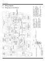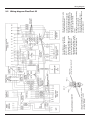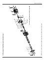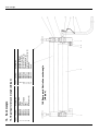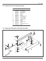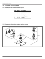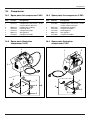
1
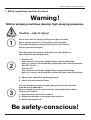
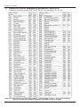
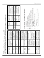
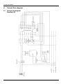
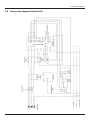
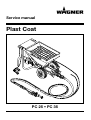
Service manual
Plast Coat
PC 25 • PC 35
Edition 09/2001 GB
0348 868
Table of contents
Table of contents
Page
1.
2.
3.
Safety regulations warning directions ................
Safety regulations ................................................
Important notes on product liability ........................
1
2
3
4.
5.
Technical data........................................................
Tool specification ....................................................
3
3
6.
6.1
Spare parts ............................................................
Spare parts list mortar spraying machine
PlastCoat 25 and 35................................................
Spare parts illustration mortar spraying machine
PlastCoat 25 and 35................................................
Spare parts list throat piece with pressure gauge ..
Spare parts illustration throat piece
with pressure gauge ................................................
Spare parts list control unit ....................................
Spare parts illustration control unit ........................
4-9
10
7.5
7.6
Frequency converter ............................................
Frequency converter control panel
and function overview ............................................
Frequency converter programming ........................
Frequency converter programming parameters
PlastCoat 25............................................................
Frequency converter programming parameters
PlastCoat 35............................................................
Error code display on the frequency converter ......
Requesting the last three error messages ..............
8.
8.1
8.2
Current flow diagram ............................................
Current flow diagram PlastCoat 25 ........................
Current flow diagram PlastCoat 35 ........................
14
14
15
9.
9.1
9.2
Wiring diagram ......................................................
Wiring diagram PlastCoat 25 ..................................
Wiring diagram PlastCoat 35 ..................................
16
16
17
Spur wheel back-gear ..........................................
Servicing spur wheel back-gear..............................
Spare parts list spur wheel back-gear ....................
Spare parts illustration spur wheel back-gear ........
Removing and installing the motor pinion
of the back-geared motor ......................................
10.5 Spare parts list back-geared motor ........................
10.6 Spare parts illustration back-geared motor ............
18
18
18
19
11.
11.1
11.2
11.3
11.4
11.5
11.6
22
22
22
23
23
24
24
6.2
6.3
6.4
6.5
6.6
7.
7.1
7.2
7.3
7.4
10.
10.1
10.2
10.3
10.4
Mortar hoses..........................................................
Spare parts list mortar hose DN 19 – 2 m ..............
Spare parts illustration mortar hose DN 19 – 2 m ..
Spare parts list mortar hose DN 19 – 10 m ............
Spare parts illustration mortar hose DN 19 – 10 m
Spare parts list mortar hose DN 19 – 20 m ............
Spare parts illustration mortar hose DN 19 – 20 m
PlastCoat 25 • 35
4
5
6
7
8
9
10
10
11
12
13
13
20
20
21
11.7
11.8
11.9
11.10
Page
Spare parts list mortar hose DN 27 – 10 m ............
25
Spare parts illustration mortar hose DN 27 – 10 m
25
Spare parts list mortar hose DN 35 – 13,3 m..........
26
Spare parts illustration mortar hose DN 35 – 13,3 m 26
12. Application gun......................................................
12.1 Spare parts list application gun ..............................
12.2 Spare parts illustration application gun ..................
27
27
27
13. Spray lances ..........................................................
13.1 Spare parts list spray lance without
automatic control ....................................................
13.2 Spare parts illustration spray lance without
automatic control ....................................................
13.3 Spare parts list spray lance with
automatic control (old type) ....................................
13.4 Spare parts illustration spray lance with
automatic control (old type) ....................................
13.5 Spare parts list spray lance with
automatic control (new type) ..................................
13.6 Spare parts illustration spray lance with
automatic control (new type) ..................................
13.7 Spare parts list rendering lance 200 U....................
13.8 Spare parts illustration rendering lance 200 U ........
13.9 Spare parts list double spray lance (old type) ........
13.10 Spare parts illustration double spray lance
(old type)..................................................................
13.11 Spare parts list double spray lance (new type) ......
13.12 Spare parts illustration double spray lance
(new type) ................................................................
28
14.
14.1
14.2
14.3
14.4
28
28
29
29
30
30
31
31
32
33
34
35
Sack mangle ..........................................................
Spare parts list sack mangle (old type) ..................
Spare parts illustration sack mangle (old type) ......
Spare parts list sack mangle (new type) ................
Spare parts illustration sack mangle (new type) ....
36
36
36
37
37
15. Container suction system ....................................
15.1 Spare parts list container suction system ..............
15.2 Spare parts illustration container suction system ..
38
38
38
16.
16.1
16.2
16.3
16.4
Compressor ..........................................................
Spare parts list compressor V 400 ..........................
Spare parts illustration compressor V 400 ..............
Spare parts list compressor C 350..........................
Spare parts illustration compressor C 350..............
39
39
39
39
39
17.
17.1
17.2
17.3
Accessories ..........................................................
Accessories for PlastCoat 25 and 35......................
Accessories illustration PlastCoat 25 and 35..........
Accessories illustration PlastCoat 25 and 35..........
40
40
41
42
WAGNER-customer service depots ..............................
43
Safety regulations warning directions
1. Safety regulations warning directions
Warning !
Mortar spraying machines develop high spraying pressures.
Caution – risk of injury!
Danger
Never reach into the spray jet with your fingers or hands!
Never aim the spray lance at yourself or other persons!
The materials sprayed cause chemical burns or irritations!
Protect your skin and eyes!
Each time before starting up, follow the procedure below as
specified in the Operating manual:
1. PlastCoat 25
Only connect to the mains supply using a special distributing
point, e.g. using a site distribution system with fault current protection
with INF ≤30 mA.
PlastCoat 35
Only connect to the mains supply using a special distributing
point, e.g. using a site distribution system with fault current protection.
2. Observe the admissible working pressures.
3. Check all connections for leaks.
The instructions for regular cleaning and servicing of the machine
must be strictly adhered to.
Before starting any work on the machine and during breaks, follow
the procedure below:
1. Note the setting time of the material.
2. Relieve the pressure in the spray lance and hose.
3. Switch the machine off.
Be safety-conscious!
PlastCoat 25 • 35
1
Safety regulations
2. Safety regulations
8.
Prevent the socket for the remote control on the
control unit from getting dirty.
Always leave the coupler plug of the remote control
line on the mortar hose screwed complete into the
control unit.
9.
Danger of injury from the screw
conveyor.
Never put your hands into the
receptacle when the mortar sprayDanger ing machine is running.
Never turn on the mortar spraying machine when
the grating has been removed from the receptacle, when the receptacle has been removed or
if there is no container connection plate.
All local safety regulations in force must be observed.
For safe operation of the mortar spraying machines,
always comply with the following specific instructions:
1.
Use of the mortar spraying machines
The mortar spraying machines PlastCoat 25
and 35 are designed only for the spraying of the
materials described in the Operating manual.
Any other use is not permitted. The manufacturer
cannot be held liable for any damage resulting
from this. In such cases, the risk will be borne
solely by the user.
Intended use also includes compliance with the
Operating manual and compliance with the inspection and servicing conditions.
Always keep the Operating manual ready at hand
at the machine location.
2.
The mortar spraying machines PlastCoat 25 and
35 may only be operated with a pressure gauge.
Only the mortar hose prescribed by the manufacturer may be used.
3.
Only use identified mortar hoses with an operating pressure of at least 40 bar.
4.
Personnel safety
Always wear protective goggles, protective clothing
and gloves and, if necessary, skin barrier cream and
breathing equipment, to protect your eyes, skin and
respiratory system.
Never uncouple mortar hose while it is still under
pressure.
Note pressure gauge!
Wear protective goggles!
Never aim spray lance at any person!
5.
Breathing masks
Breathing masks must be provided for the operator
to protect against mineral dust.
6.
PlastCoat 25
Only connect to the mains supply using a special
distributing point, e.g. using site distribution
system with fault current protection with
INF ≤ 30 mA.
PlastCoat 35
Only connect to the mains supply using a special
distributing point, e.g. using a site distribution
system with fault current protection.
7.
The master switch has an EMERGENCY OFF
function.
2
10. Cleaning and servicing
Never uncouple mortar hoses under pressure.
Before uncoupling, check pressure on the pressure
gauge.
Turn off the mortar spraying machine for cleaning
and maintenance work. Pull out mains plug and
ensure that it cannot be plugged back in unintentionally.
Do not spray the motor or control unit of the mortar
spraying machine with water jet, high-pressure or
steam cleaning equipment. Water could penetrate
the machine and cause a short-circuit.
11. Electrical equipment
Work on the machine’s electrical equipment may be
carried out only by a qualified electrician.
The electrical equipment must be inspected regularly. Defects such as loose connections or scorched
cables must be remedied immediately.
12. Keep the labels on the mortar spraying machine
clean and legible.
13. Positioning on uneven ground
The front of the mortar spraying machine must point
upwards to avoid that the machine slips away.
PlastCoat 25 • 35
Technical data
Tool specification
3. Important notes on product
liability
As a result of an EC regulation being effective as from
January 1, 1990, the manufacturer shall only be liable
for his product if all parts come from him or are released
by him, and if the devices are properly mounted and
operated.
If the user applies outside accessories and spare parts,
the manufacturer´s liability can fully or partially be inapplicable; in extreme cases usage of the entire device can
be prohibited by the competent authorities (employer´s
liability insurance association and factory inspectorate
division).
Only the usage of original WAGNER accessories and
spare parts guarantees that all safety regulations are
observed.
5. Tool specification
Carrier sleeve take-off device
Part No.
0348 950
4. Technical data
PlastCoat 25
Voltage:
Fuse protection:
Device mains cable
6 m long:
Motor output P1:
Max. feed rate (water)
Pump yellow:
Pump brown:
Pump green:
Max. operating pressure:
Max. grain size:
PlastCoat 35
230 V ~, 50 Hz
400 V, 50 Hz, V3 ~
16 A slow-blow
3 x 2.5 mm2
5 x 1.5 mm2
2.2 kW
3.6 kW
10 l/min
15 l/min
20 l/min
15 l/min
20 l/min
25 l/min
40 bar
G 5 mm
Measurements L x W x H:
1200 x 520 x 660 mm
Receptacle capacity:
60 l
Weight:
85 kg
87 kg
Tire pressure, max.:
2 bar
Protective system:
Max. sound pressure level:
IP 54
77 dB (A)*
Atomization air connection:
Rapid action coupling
DN 7 mm
10 bar
Max. atomization air pressure:
Required volume of
compressed air, min:
Texture nozzle:
Mortar hose:
220 l/min
8 mm (standard)
DN 27 mm, 10 m (standard)
* Measuring point: At a distance of 1m to the side of the unit and
at a height of 1.60 m above floor, reverberant floor.
PlastCoat 25 • 35
3
4
25
26
27
30
5
6
7
9
10
11
12
14
15
16
17
18
19
21
22
23
24
1
2
3
4
0348 363
9982 820
9982 823
0348 230
–––––––
9900 204
9920 102
9900 125
0348 334
9972 331
0348 400
9971 171
9930 913
0348 324
9921 518
0348 313
9922 746
0348 314
0348 329
0348 307
9900 109
0348 396
–––––––
9910 107
0348 310
0348 306
9910 208
Item Part No.
PlastCoat 25
0348 363
9982 820
9982 823
–––––––
0348 231
9900 204
9920 102
9900 125
0348 334
9972 331
0348 400
9971 171
9930 913
0348 324
9921 518
0348 313
9922 746
0348 314
0348 329
0348 307
9900 109
–––––––
0348 397
9910 107
0348 310
0348 306
9910 208
Part No.
PlastCoat 35
Motor cable
Cable screw connection
Adapter
Transmission motor 230 V~, 50 Hz
Transmission motor 400 V, 50 Hz, V3~
Hexagon screw M 8 x 35 DIN 931 (2)
Washer A 8,4 DIN 125
Hexagon screw M 8 x 50 DIN 933
Supporting ring
Grooved ring 32 x 50 x 10
Intermediate flange
O-Ring 90 x 3,5
Straight pin 8 x 40
Screw
Lock washer B12 DIN 127
Carrier bush
Snap ring A 45
Feed screw
Grating
Receptacle
Hexagon screw M 8 x 25 DIN 933
Type plate PlastCoat 25
Type plate PlastCoat 35
Hexagon nut M8 DIN 934
Receptacle seal
Receptacle lower part
Hexagon nut M 8 DIN 985
Designation
51
52
53
54
9900 118
0348 316
0348 315
9990 368
0342 321
0348 233
9990 618
9970 109
9991 946
9991 947
0348 349
9994 902
0348 419
9900 317
9990 863
0348 318
9920 103
9910 204
0348 347
–––––––
0348 424
9982 822
9951 063
9951 078
––––––––
9992 834
31
32
33
34
35
36
37
38
39
40
41
42
43
44
45
46
47
48
49
50
9900 118
0348 316
0348 315
9990 368
0342 321
0348 233
9990 618
9970 109
9991 946
9991 947
0348 349
9994 902
0348 419
9900 317
9990 863
0348 318
9920 103
9910 204
0348 347
0348 422
–––––––
9982 822
9951 063
9951 078
––––––––
9992 834
Part No.
PlastCoat 35
Item Part No.
PlastCoat 25
Hexagon screw M 8 x 30 DIN 933
Pump screw yellow W 10/3 (standard)
Pump jacket yellow W 10/3 (standard)
Star grip M 16
Adapter fix-nipple V 35-M 27
Outlet unit
Coupling
Sealing ring
Pressure gauge
Protective cap
Wheel
Wheel cap
Trolley frame
Cheese head screw M 8 x 50 DIN 912
Pipe end cap
Drawbar tube right
Washer A 6,4 DIN 125
Hexagon nut M 6 DIN 985
Drawbar pipe left
Device mains connection H07 RN-F3G2,5 – 6 m
Device mains connection H07 RN-F5G1,5 – 6 m
Cable screw connection
Hexagon nut
Hexagon nut
EP long-life grease lubricant, quantity 25 g
EP long-life grease 400 g
Designation
6.1 Spare parts list mortar spraying machine PlastCoat 25 and 35 (Spare parts illustration, see page 5)
6. Spare parts
Spare parts
PlastCoat 25 • 35
PlastCoat 25 • 35
1
2
50
53
1
46
51
2
52
7
43 42
30
45 44
3
6
4
41
5 6
47
10
48
9
54 25g
11
49
12
14
15
16
17
36
19
39 40
38
37
18
35
24
6.2 Spare parts illustration mortar spraying machine PlastCoat 25 and 35
6
30
34
30
6
31
15
16
33
22
23
SAL PlastCoat 25 03/01
32
27
25
6
26
21
Spare parts
5
6
Hose piece
Hydraulic oil NUTO H 22 – 1 litre
Loctite fast cleaner 7063 – 400 ml
Loctite 243 – 50 ml
0348 413
0348 414
9991 946
9991 947
9970 109
9990 618
0349 418
0021 061
9992 821
9992 511
3
4
5
6
7
8
9
Coupling
Sealing ring
Protective cap
Pressure gauge
Threaded connector
Housing
Collet
0348 412
2
Crosshead
Pressure transmitter filling with hydraulic oil Nuto H 22
quality: 32 g (26 ml)
Pos. 3 with Pos. 1 and Pos. 4 bonded with Loctite 243
Pos. 4 with Pos. 8 bonded with Loctite 243
Prepare the adhesive area with fast cleaner typ 7063
Throut piece with pressure gauge
0348 233
0348 411
Designation
Part No.
Item
1
Spare parts list throat piece with pressure gauge
6.3
Spare parts
PlastCoat 25 • 35
6.4
PlastCoat 25 • 35
At mounting grease
At mounting grease
Spare parts list illustration throat piece with pressure gauge
Spare parts
7
8
0348 363
9982 822
9951 063
9982 820
0348 398
9951 078
9990 554
9910 108
9921 504
9900 353
9920 104
29
9920 104
0348 363
9982 822
9951 063
9982 820
0348 399
9951 078
9990 554
9910 108
9921 504
9900 353
0348 424
––––––––
9992 821
9992 590
9992 664
9992 835
9992 821
9992 590
9992 664
9992 835
9910 708
9952 405
3053 925
0348 392
9900 344
9921 505
0348 436
0348 443
0348 240
0348 444
0348 445
0348 446
9906 005
43
51
54
56
61
9900 346
9950 372
0348 408
0348 467
0348 468
0348 469
0348 470
9902 201
9902 218
––––––––
0348 436
0348 443
0348 240
0348 444
0348 445
0348 446
9906 005
9910 708
––––––––
3053 925
0348 392
––––––––
42
63
64
65
66
68
69
70
71
9900 346
41
9902 218
Recessed pan head
head tapping screw
BZ 2,9 x 9,5 DIN 7981 (2)
Earthing mark
Instruction sticker „D“
Instruction sticker „GB“
Instruction sticker „F“
Instruction sticker „E“
Instruction sticker „NL“
Recessed pan head
tapping screw
3,9 x 9,5 DIN 7981 (6)
Cylindrical head screw
M6 x 12 DIN 912 (2)
Cap nut M6 DIN 986 (2)
Ferrite sleeve
Mounting base, adh. clips (4)
Profil cord
Cylindrical head screw
M 5 x 12 DIN 912 (2)
Lock washer B5 DIN 127 (2)
Rubber buffer
Ventilator 230 V~, 50 Hz
Ventilator cable
Trough
Impact plate
Separation plate
Cylindrical head screw
M 4 x 35 DIN 912 (2)
Loctite fast cleaner
7063 – 400 ml
Loctite 222 – 50 ml
Loctite 414 – 20 g
Acrylic sealant –
310 ml cartouche
Part No.
Part No.
Designation
PlastCoat 25 PlastCoat 35
9950 372
0348 408
0348 467
0348 468
0348 469
0348 470
9902 201
39
40
31
0348 236
0348 407
0348 409
0348 403
––––––––
0348 752
0348 405
0348 406
0348 373
0268 591
9950 814
9952 607
9952 660
3026 614
3025 151
9952 669
0348 410
3050 081
––––––––
0348 232
0348 407
0348 409
0348 403
0348 751
––––––––
0348 371
0348 406
0348 373
0268 591
9950 814
9952 607
9952 660
3026 614
3025 151
9952 669
0348 410
3050 081
0348 422
Control unit
Electronic housing
Electronic housing over
Support sheet
Frequency converter 2,2 kW
Frequency converter 4 kW
Suppression filter
Master switch 0 – 1
Changeover switch
Potentiometer
Sealing nut
Rotary knob
Rotary knob cap
Ind. lamp front
Ind. lamp fitting
Socket
Electronic housing seal
Glow lamp
Mains cable
H07 RN-F3G2,5 – 6 m
Mains cable
H07 RN-F5G1,5 – 6 m
Motor cable
Cable screw connection
Hexagon nut
Cable screw connection
Information plate
Hexagon nut
Protective cap
Hexagon nut M4 DIN 934
Lock washer B4 DIN 127
Cylindrical head screw
M4 x 12 DIN 912
Washer A 4,3 DIN 125
Item
Part No.
Part No.
Designation
PlastCoat 25 PlastCoat 35
18
19
20
21
22
24
25
26
27
28
5
6
7
8
9
10
11
12
13
14
15
16
17
1
2
3
4
Item
6.5 Spare parts list control unit
Spare parts
PlastCoat 25 • 35
6.6 Spare parts illustration control unit
PlastCoat 25 • 35
PlastCoat 35
Ferrite sleeve (item 51) installed on
wires 1 and 2 of the wiring harness.
(3 adhesive points distributed about
length)
Part 56 with part 1 bonded with
Loctite 414
Part 42 with part 43 bonded with
Loctite 222
All adhesive area with fast cleaner
7063 prepare
All welding groove except the right
trailing edge to sealed with acrylic
sealing compound at bottem plate
Spare parts
9
Frequency converter
7. Frequency converter
The frequency converter has already been programmed for replacement as a spare part.
Frequency converter
PlastCoat 25 – Part No. 0348 751
PlastCoat 35 – Part No. 0348 752
7.1
Frequency converter control panel and function overview
Red LED on for external frequency
specification (Fn_11=1/2/3)
Red LED on for right-handed rotation
Red LED on for external rotation
direction specification (Fn_10=1)
Red LED on for left-handed rotation
Red LED on for output frequency
or speed display
Red LED on: output voltage display
If red LED is on, FC is in programming mode
Start/stop command (Fn_10=0)
Red LED on: motor current display
Program selection
Increase/decrease values
Rotation direction specification (Fn_10=0)
Potentiometer (Fn_11=1)
Acknowledge error or move cursor from
ones to tens to hundreds digit
Key for displaying and storing
parameters
7.2
Frequency converter programming
1.
2.
3.
Connect to mains
Move main switch to "I" position.
Move rotation direction switch to "0".
Warning: do not touch any live components.
Press "DSP/FUN" button, "F000" appears in display.
Select required function number by pressing the "▲" and "▼" buttons.
The "</RESET" button is used to select the ones, tens and hundreds digits.
Switch from the function number display to the selected function number setting display using the
"READ/ENTER" button.
Set the value as specified in the "Parameter list" using the "</RESET" and "▲" and "▼" buttons.
Press "READ/ENTER" to store the setting. "FXXX" appears in the display again.
Select next function number using "▲" and "▼" and proceed in same order.
After storing the last setting, press the "DSP/FUN" button twice to leave programming mode and switch back
to the original display.
4.
5.
6.
7.
8.
9.
10.
10
PlastCoat 25 • 35
Frequency converter
7.3
Frequency converter programming parameters PlastCoat 25
Frequency converter model: WATTtronic 22 S3, list produced on 15. 05. 00
*Attention: F098 must be set before F056. If F056 is set before F098, contacts 1 and 2 on the frequency
converter terminal strip should be jumpered so that F056 can be set to 0100.
PlastCoat 25 • 35
11
Frequency converter
7.4
Frequency converter programming parameters PlastCoat 35
Frequency converter model: WATTtronic 40 H3, list produced on 01. 03. 00
*Attention: F098 must be set before F056. If F056 is set before F098, contacts 1 and 2 on the frequency
converter terminal strip should be jumpered so that F056 can be set to 0100.
12
PlastCoat 25 • 35
Error code display on the frequency converter (FC)
PlastCoat 25 • 35
1. Operate the feed unit with the capacity regulator set to “0”
until the pump has broken free. Lubricate pump.
1. Check load on motor; use
mortar hose with shorter length or
greater diameter. Check that the
material to be fed in can be pumped
1. Replace FC; contact the nearest
Wagner Service branch office
1. Check load on motor; use
mortar hose with shorter length or
greater diameter. Check that the
material to be fed in can be pumped
1. Check load on motor, use
mortar hose with shorter length or
greater diameter. Check that the
material to be fed in can be pumped
1. Switch off mains switch and
allow motor to cool down
1. Replace FC; contact the nearest
Wagner Service branch office
1. Replace FC; contact the nearest
Wagner Service branch office
1. Fixed pump
1. Load on motor too
high
1. FC defective
1. Load on motor too high
1. Load on motor too high
1. Motor overheated.
Motor can overheat
when set to a low feed
quantity and under high
load.
2. Lines to thermal switch
in motor coil have
become detached or are
defective
3. Jumper link on FC
terminal strip has
become detached
1. EPROM defective
1. Intermediate circuit
detection defective
Overcurrent
during
acceleration
Overcurrent
at constant
speed
Overcurrent
at standstill
Motor overload
Frequency
converter
overload
Emergency stop
via TM2
terminals
Overvoltage
at standstill
Overvoltage
at standstill
OC-C
- OC -
OL1
OL2
E.S.
EPR
- OV -
2. Replace FC; contact the nearest
Wagner Service branch office
2. Intermediate circuit
detection defective
Move main switch to „I“ position.
Move rotation direction switch to „0“.
2.
3.
Press „DSP/FUN“ button, „F000“ appears in display.
Enter function No. “F125” with the „▲“ and „▼“ buttons.
The „< / RESET“ button is used to select the ones, tens and
hundreds digits.
Press „READ/ENTER“ to store the setting.
The „▲“ and „▼“ buttons can be used to request the last
three error messages.
Press the „READ/ENTER“ button once and the „DPS/FUN“
button twice to go back to the initial display.
4.
5.
6.
7.
8.
3. Check jumper link from
terminal No. 1 to terminal
No. 5 on FC
Warning: do not touch any live components.
Connect to mains
2. Ensure constant line voltage
2. Voltage in the power
supply not constant
1.
1. Check line voltage, use extension
cable with a larger metallic section
(2.5 mm2) if necessary
1. Low voltage in the power
supply
Requesting the last three error messages
Low voltage at
constant speed
1. Ensure that ambient temperature
is acceptable
1. Check line voltage, use extension
cable with a larger metallic section
(2.5 mm2) if necessary
What to do
1. Low voltage in the power
supply
Heatsink of the FC 1. Ambient temperature
too high
is overheated
Low voltage at
standstill
Probable Cause
7.6
LV-C
- OH - OH-C -
- LV -
Fault Code Content
2. Check motor lines No. 4 and 5 from
terminal strip of the FC
to the motor terminal board
2. Replace FC; contact the nearest
Wagner Service branch office
OC-A
1. Check motor and motor lines
1. Short circuit or ground
fault at FC output
2. Output transistors
defective
Overcurrent
when starting
What to do
Probable Cause
OC-S
Fault Code Content
Error messages can be deleted by pressing the “RESET” button or by switching off the mains switch (for a minimum of 10 sec.).
7.5
Frequency converter
13
Current flow diagram
8.
Current flow diagram
8.1
Current flow diagram
PlastCoat 25
14
PlastCoat 25 • 35
Current flow diagram
8.2
Current flow diagram PlastCoat 35
PlastCoat 25 • 35
15
9.1
Wiring diagram PlastCoat 25
16
Slide the spiral hose (255 mm) over the
cable from the stranded wires 0348 430
and the ventilator cable 0348 240.
Wiring diagram
Attention:
Install device connecting cable to fastening
base with a separate cable tie.
Securing of the device connecting cable
0348 422, the stranded wires 0348 430,
the ventilator cable 0348 240 and the wire
harness 0348 427 to the fastening bases
3053 925 with cable ties 9994 670.
Slide the spiral hose (295 mm) over cables
from wiring harness 0348 427.
9.
Slide the spiral hose (420 mm) over the
brown and blue cable of the device
connecting cable 0348 422.
Cut one 420-mm piece, one 255-mm
piece and one 295-mm piece from the
spiral hose 3110 905.
Wiring diagram
PlastCoat 25 • 35
PlastCoat 25 • 35
Slide ferrite sleeve 9952 405 on side of
socket 9952 669 over both blue cables from
wire harness 0348 427.
Attention:
Install device connecting cable to fastening
base with a separate cable tie.
Securing of the device connecting cable
0348 424, the stranded wires 0348 432,
the ventilator cable 0348 240 and the wire
harness 0348 427 to the fastening bases
3053 925 with cable ties 9994 670.
Slide the spiral hose (295 mm) over cables
from wiring harness 0348 427.
Wiring diagram PlastCoat 35
Slide the spiral hose (255 mm) over the
cable from the stranded wires 0348 432
and the ventilator cable 0348 240.
9.2
Slide the spiral hose (420 mm) over the
brown, blue and black cable of the
device connecting cable 0348 424.
Cut one 420-mm piece, one 255-mm
piece and one 295-mm piece from the
spiral hose 3110 905.
Wiring diagram
17
18
Spur wheel back-gear
Part No.
PlastCoat 25
9900 315
9921 502
9910 102
0348 756
0348 758
0348 759
9922 602
0348 766
0348 762
0348 771
0348 767
0348 769
0348 770
Item
1
2
3
4
5
6
7
9
10
11
12
13
14
0348 770
0348 769
0348 768
0348 771
0348 762
0348 766
9922 602
0348 759
0348 758
0348 756
9910 102
9921 502
9900 315
Shim ring
Cylindrical pin
Gear wheel 1st-level toothed gear
Shim ring
Securing ring
Shim ring
Securing ring 62 x 2
Shaft seal ring
Shaft seal ring
Drive flange
Hexagon nut M6 (4)
Lock washer A6 (4)
Cylinder head screw M 6 x 25 (4)
Part No.
PlastCoat 35 Designation
10.2 Spare parts list spur wheel back-gear
9921 501
9910 107
28
0348 753
0348 760
0348 765
0348 763
9900 312
0348 761
0348 755
9998 144
0348 757
0348 792
0348 772
Part No.
PlastCoat 25
27
26
25
24
23
22
21
19
18
17
16
15
Item
Oil type if spur wheel back-gear replaced
Gear oil in accordance with DIN 51 502 CLP, viscosity class in accordance with ISO VG 220
DIN 51 519, e.g. Esso Spartan EP 220.
Oil quantity: 0,55 litres
9910 107
9921 501
0348 754
0348 760
0348 765
0348 764
9900 312
0348 761
0348 755
9998 144
0348 757
0348 792
0348 772
Part No.
PlastCoat 35
No oil change is required.
The oil should have enough lubricating effect to last the lifetime of the spur wheel back-gear.
10.1 Servicing spur wheel back-gear
10.
Hexagon nut M 8 (4)
Lock washer A 8 (4)
Electric motor
Stud (4)
Pinion bushing
Modular pinion
Cylinder head screw M 6 x 20 (6)
Screw plug
Access cover
Securing ring 15 x 1
Dowel pin
Shim ring
Shim ring
Designation
Spur wheel back-gear
PlastCoat 25 • 35
PlastCoat 25 • 35
2 3
5
7
9
10
11
18
19
22
13
14, 15, 16
17
21
23
24
25
26
27
28
Insert shim rings appropriate for the relevant gap width
12
ATTENTION: It is extremely important to supply the gear type and number when ordering spare parts!
1
4
6
10.3 Spare parts illustration spur wheel back-gear
Spur wheel back-gear
19
20
0348 777
9900 224
0348 778
0348 779
0348 780
0348 781
9903 314
4
5
6
7
8
9
10
0348 783
0348 776
3
15
0348 775
2
0348 782
0348 773
1
14
Part No.
PlastCoat 25
Item
0348 783
0348 782
9903 314
0348 781
0348 780
0348 779
0348 778
9900 224
0348 777
0348 776
0348 775
0348 774
Part No.
PlastCoat 35
Bearing end cover
Screw (3)
M4 x 16 (4)
Raised cheese head screw
Terminal box cover
Seal
Terminal box
Seal
Cylinder head screw M 6 x 25 (4)
Screw plug
Ball bearing alignment washer
Shaft seal ring
Rotor
Designation
10.5 Spare parts list back-geared motor
––––––––
0348 789
9922 603
0348 784
0348 785
0348 786
0348 787
9922 506
0348 788
––––––––
17
18
19
20
23
24
25
0348 791
9992 821
9992 804
0348 791
9992 821
9992 804
27
0348 790
0348 790
26
9922 506
0348 787
0348 786
0348 785
0348 784
9922 603
Part No.
PlastCoat 25
Item
Part No.
PlastCoat 35
Loctite 648 – 50 ml
Loctite fast cleaner 7063 – 400 ml
Ball bearing
Motor flange
Stator 400 V 3 ~
Stator 230 V ~
Securing ring 25 x 1,2
Shaft seal ring
Fan cowl
Fan
Ball bearing
Securing ring 52x 2
Designation
Installation
1. Replace shaft seal.
2. Clean motor shaft and bore in the motor pinion with Loctite fast cleaner, type 7063.
3. Heat motor pinion to 140°C in an oven.
4. Apply a thin film of Loctite 648 to the cleaned adherend of the motor shaft with a brush.
5. Set the hot motor pinion to the correct position on the motor shaft with a pair of tongs. Then press on the motor pinion with the hand press
in one go.
6. When pressing, do not set it down; the glue hardens immediately. If careful attention is not paid, the glue will not stick when pressed again.
Removal
1. Place the two reinforcing rod spacers on the motor pinion.
2. Heat the motor shaft in several locations with a welding torch.
3. Remove motor pinion from the motor shaft.
10.4 Removing and installing the motor pinion of the back geared-motor
Spur wheel back-gear
PlastCoat 25 • 35
PlastCoat 25 • 35
27
1
2
3
4
5
26
6
7
8
9
10
25
14
15
5
17
18
24
23
20
19
ATTENTION: It is extremely important to supply the gear type and number when ordering spare parts !
10.6 Spare parts illustration back-geared motor
Spur wheel back-gear
21
22
Mortar hose DN 19 – 2 m
Mortar hose
Plug
Control cable with pos. 2 and 7
Cable clamp
Air hose
Coupling plug
0342 255
0268 614
9952 672
0268 613
9992 610
0268 612
9952 673
1
2
3
5
6
7
Union nut round
thread connection
32 x 1/8 in
11.2 Spare parts illustration mortar hose DN 19 – 2 m
Designation
Part No.
Item
11.1 Spare parts list mortar hose DN 19 – 2 m
11. Mortar hoses
Length:
(4x) 300
Nipple
Plug/coupling contact layout
blue line
contact 1
brown line contact 2
Plug/coupling layout diagram
Mortar hoses
PlastCoat 25 • 35
PlastCoat 25 • 35
Mortar hose DN 19 – 10 m
Mortar hose
Plug
Control cable with pos. 2 and 6
Cable clamp (22)
Air hose
Coupling plug
0348 909
0348 914
9952 672
0342 248
9994 695
0342 247
9952 673
1
2
3
4
5
6
Union nut round
thread connection
32 x 1/8 in
11.4 Spare parts illustration mortar hose DN 19 – 10 m
Designation
Part No.
Item
11.3 Spare parts list mortar hose DN 19 – 10 m
Length:
Nipple
Plug/coupling contact layout
blue line
contact 1
brown line contact 2
Plug/coupling layout diagram
Mortar hoses
23
24
Mortar hose DN 19 – 20 m
Mortar hose
Plug
Control cable with pos. 2 and 6
Cable clamp (42)
Air hose
Coupling plug
0348 930
0348 932
9952 672
0348 934
9994 695
0348 933
9952 673
1
2
3
4
5
6
Union nut round
thread connection
32 x 1/8 in
11.6 Spare parts illustration mortar hose DN 19 – 20 m
Designation
Part No.
Item
11.5 Spare parts list mortar hose DN 19 – 20 m
Length:
(41x) 435
Nipple
Plug/coupling contact layout
blue line
contact 1
brown line contact 2
Plug/coupling layout diagram
Mortar hoses
PlastCoat 25 • 35
PlastCoat 25 • 35
Mortar hose DN 27 – 10 m
Mortar hose
Plug
Control cable with pos. 2 and 6
Cable clamp (22)
Air hose
Coupling plug
0348 912
0342 225
9952 672
0342 248
9994 695
0342 247
9952 673
1
2
3
4
5
6
Coupling
Length:
Length:
11.8 Spare parts illustration mortar hose DN 27 – 10 m
Designation
Part No.
Item
11.7 Spare parts list mortar hose DN 27 – 10 m
Nipple
Plug/coupling contact layout
blue line
contact 1
brown line contact 2
Plug/coupling layout diagram
Mortar hoses
25
26
Mortar hose DN 35 – 13,3 m
Mortar hose
Plug
Control cable with pos. 2 and 6
Cable clamp (29)
Air hose
Coupling plug
0348 946
0342 250
9952 672
0342 252
9994 695
0342 251
9952 673
1
2
3
4
5
6
Coupling
Length:
Length:
11.10 Spare parts illustration mortar hose DN 35 – 13,3 m
Designation
Part No.
Item
11.9 Spare parts list mortar hose DN 35 – 13,3 m
Nipple
Plug/coupling contact layout
blue line
contact 1
brown line contact 2
Plug/coupling layout diagram
Mortar hoses
PlastCoat 25 • 35
Application gun
12. Application gun
12.1 Spare parts list application gun
Item
1
2
3
4
5
6
7
8
9
10
11
12
Part No.
Designation
Item
Part No.
Designation
0342 246
Application gun, connection V 27
for the application of heat insulation
composite system adhesive
Outlet
Claw coupling*
Support
Nozzle
Service set: application gun
Housing
Valve stem
Guide bushing
Magnet
Spring plate
Compression spring
Screw plug
15
16
17
18
20
21
22
23
24
25
26
0342 378
9910 403
0342 727
0342 383
0342 286
0342 384
9951 079
0342 403
9952 672
9952 864
0342 255
27
0342 272
Pin
Cap nut M4*
Trigger
Reduction
Control cable
Handle
Cable screw connection
Grip handle
Plug
Resistor 330 Ohm
Mortar hose DN 19 mm – 2 m
(with control cable and air hose)
Swivel joint
9992 511
* Loctite 243 – 50 ml
0342 256
0342 307
0342 373
0342 374
0342 726
0342 375
0342 376
0342 380
9953 437
0342 381
9994 300
0342 382
+ 0,1
0,2
11,4
12.2 Spare parts illustration
application gun
7
6
5
4
5
3
8
9
10
11
12
2
15
18
16
1
27
20
26
17
Layout diagram in plug, item 24
25
23
21
24
20
Contact layout of plug (item 24)
blue line
contact 1
brown line
contact 3
Resistor
between contact 2
(item 25)
and contact 3
PlastCoat 25 • 35
24, 25
22
27
Spray lances
13. Spray lances
13.1 Spare parts list spray lance without automatic control
Item
1
2
3
4
5
6
7
8
9
10
Part No.
Designation
Spray lance
100 mm long
0342 200
0268 779
0348 915
0268 780
0348 916
0268 781
0348 917
0268 782
0342 327
0342 350
0342 351
0268 604
9991 112
0268 470
0342 469
9991 111
9983 237
9983 238
0342 313
Spray lance without automatic control
Texture nozzle 4
Texture nozzle 5
Texture nozzle 6
Texture nozzle 7
Texture nozzle 8 (standard)
Texture nozzle 9
Texture nozzle 10
Texture nozzle 12
Sealing washer
Union nut
Air hose*
Ball tap*
Nozzle head
Material pipe*
Ball tap
Double nipple 3/4 in – 1 in
Double nipple 3/4 in – round thread 32 x 1/8 in
Fix nipple connection V 27 *
9992 590
* Loctite 222 – 50 ml
13.2 Spare parts illustration spray lance without automatic control
1
2
3
4
5
10
9
8
7
28
6
PlastCoat 25 • 35
Spray lances
13.3 Spare parts list spray lance with automatic control (old type)
Item
1
2
3
4
5
6
7
Part No.
Spray lance
Part No.
Designation
Spray lance
(ceiling spray
lance)
100 mm long 800 mm long
0348 224
0348 904
0348 919
0348 904
0348 923
––––––––
9910 204
3050 347
0348 225
3051 679
0348 354
0348 921
0348 942
0348 355
0268 779
0348 915
0268 780
0348 916
0268 781
0348 917
0268 782
9910 204
3050 347
0348 225
3051 679
–––––––
0348 921
0348 942
0348 355
0268 779
0348 915
0268 780
0348 916
0268 781
0348 917
0268 782
Item
Spray lance with automatic control
Extension kit 500 mm long
(material pipe and air pipe)
Extension kit 800 mm long
(material pipe and air pipe)
Hexagon nut M6 DIN 985
Washer 6.4 DIN 433
Lever
O-ring 35 x 2
Air pipe 100 mm long
Air pipe 800 mm long
Air pipe 500 mm long
Nozzle head
Texture nozzle 4
Texture nozzle 5
Texture nozzle 6
Texture nozzle 7
Texture nozzle 8 (standard)
Texture nozzle 9
Texture nozzle 10
8
9
10
11
12
13
14
15
16
17
18
19
20
Part No.
Spray lance
Part No.
Designation
Spray lance
(ceiling spray
lance)
100 mm long 800 mm long
0342 327
0342 350
0342 351
0348 346
0348 922
0348 943
9902 309
0348 384
0348 216
0348 226
3105 540
9991 111
9983 237
9983 238
0342 327
0342 350
0342 351
––––––––
0348 922
0348 943
9902 309
0348 384
0348 216
0348 226
3105 540
9991 111
9983 237
9983 238
0342 313
9991 112
0268 604
0342 313
9991 112
0268 604
Texture nozzle 12
Sealing washer
Union nut
Material pipe 100 mm long
Material pipe 800 mm long
Material pipe 500 mm long
Pan head tapping screw 4.2 x 16
Cover
Cable
Connection sleeve
O-ring 26 x 2
Ball tap
Double nipple 3/4 in – 1 in
Double nipple 3/4 in – round
thread 32 x 1/8 in
Fix nipple connection V 27*
Ball tap*
Air hose*
9992 590
9992 590
* Loctite 222 – 50 ml
13.4 Spare parts illustration spray lance with automatic control (old type)
1
2
3
4
18
5
4
6
17
7
16
8
15
9
14
13
12
11
20
19
PlastCoat 25 • 35
10
29
Spray lances
13.5 Spare parts list spray lance with automatic control (new type)
Item
1
2
3
4
5
6
7
Part No.
Spray lance
Part No.
Designation
Spray lance
(ceiling spray
lance)
100 mm long 800 mm long
0348 241
0348 904
0348 960
0348 904
0348 923
––––––––
9910 208
9920 102
0348 243
3051 679
0348 354
0348 921
0348 942
0348 355
0268 779
0348 915
0268 780
0348 916
0268 781
0348 917
0268 782
0342 327
9910 208
9920 102
0348 243
3051 679
–––––––
0348 921
0348 942
0348 355
0268 779
0348 915
0268 780
0348 916
0268 781
0348 917
0268 782
0342 327
Item
Spray lance with automatic control
Extension kit 500 mm long
(material pipe and air pipe)
Extension kit 800 mm long
(material pipe and air pipe)
Hexagon nut M8 DIN 985
Washer 8.4 DIN 433
Lever
O-ring 35 x 2
Air pipe 100 mm long
Air pipe 800 mm long
Air pipe 500 mm long
Nozzle head
Texture nozzle 4
Texture nozzle 5
Texture nozzle 6
Texture nozzle 7
Texture nozzle 8 (standard)
Texture nozzle 9
Texture nozzle 10
Texture nozzle 12
8
9
10
11
12
13
14
15
16
17
18
19
20
21
22
Part No.
Spray lance
Part No.
Designation
Spray lance
(ceiling spray
lance)
100 mm long 800 mm long
0342 350
0342 351
0348 346
0348 922
0348 943
9902 309
0348 460
0348 216
0348 244
3105 540
0348 461
9920 104
0268 338
9983 237
9983 238
0342 350
0342 351
––––––––
0348 922
0348 943
9902 309
0348 460
0348 216
0348 244
3105 540
0348 461
9920 104
0268 338
9983 237
9983 238
0342 313
9991 112
0268 604
0342 313
9991 112
0268 604
Sealing washer
Union nut
Material pipe 100 mm long
Material pipe 800 mm long
Material pipe 500 mm long
Pan head tapping screw 4.2 x 16
Cover
Cable
Connection sleeve
O-ring 26 x 2
Stop
Washer 4.3
Ball tap
Double nipple 3/4 in – 1 in
Double nipple 3/4 in – round
thread 32 x 1/8 in
Fix nipple connection V 27*
Ball tap*
Air hose*
9992 590
9992 590
* Loctite 222 – 50 ml
13.6 Spare parts illustration spray lance with automatic control (new type)
1
2
3
20
11
19
4
5
17
18
4
16
6
7
8
15
9
14
13
12
11
22
21
30
10
PlastCoat 25 • 35
PlastCoat 25 • 35
Rendering lance 200 U
Spraying unit M 25 – 200
Ball tap DN 25
Fix nipple V 27
Double nipple
Air hose DN 9
Rendering nozzle set 14, 16, 18
Loctite fast cleaner 7063 – 400 ml
Loctite 222 – 50 ml
0342 912
0342 914
9991 556
0342 313
9998 147
0268 604
0268 726
9992 821
9992 590
1
2
3
4
5
Po.s 1, 2, 3, 4 and 5 with Loctite 222
safeguarded and sealed
13.8 Spare parts illustration rendering lance 200 U
Designation
Part No.
Item
13.7 Spare parts list rendering lance 200 U
Spray lances
31
Spray lances
13.9 Spare parts list double spray lance (old type)
32
Item
Part No.
Designation
1
2
3
4
5
6
10
11
12
13
14
15
16
17
18
19
20
23
24
25
26
27
28
29
30
34
35
36
37
38
39
40
41
42
43
0342 275
0342 272
9983 238
9991 111
9910 204
3050 347
0348 225
3105 540
0348 226
0348 216
0348 384
9902 309
0342 479
9991 112
9983 224
9991 951
0268 604
3051 199
3051 679
0342 478
9992 323
0342 510
0342 486
9971 037
0342 484
0700 396
0342 485
0342 483
9971 112
0342 482
0342 481
0342 480
0268 470
0268 780
0342 350
0342 351
Double lance (old type) 400 mm
Swivel joint
Double nipple 3/4 in – round thread 32 x 1/8 in*
Ball tap
Hexagon nut M6
Washer 6.4
Lever
O-ring 26 x 2
Connection sleeve
Cable
Cover
Pan head tapping screw 4.2 x 16
Material pipe 400 mm long
Ball tap
Coupling fitting
Restrictor valve
Air hose*
Cable clamp (3)
O-ring 35 x 2
Air pipe 400 mm long
Screwed connection
Air hose
Deflector housing
O-ring 22 x 1.5
Shaft
Screwed connection
Support
Connection piece
O-ring 28 x 2
Screw plug
Hexagon nut
Ell
Spray head
Texture nozzle 6 mm
Sealing washer
Union nut
9992 590
*Loctite 222 – 50 ml
PlastCoat 25 • 35
Spray lances
13.10 Spare parts illustration double spray lance (old type)
4
5
6
1
2
20
3
10
11
19
13
14
18
17
15
16
12
23
24
23
26
25
37
27
36
10
28
30
26
29
10
35
34
10
30
35
37
40
41
38
39
36
42
43
40
41
42
38
43
39
PlastCoat 25 • 35
33
Spray lances
13.11 Spare parts list double spray lance (new type)
34
Item
Part No.
Designation
1
2
3
4
5
6
7
8
9
10
11
12
13
15
16
17
18
19
20
23
24
25
26
27
28
29
30
34
35
36
37
38
39
40
41
42
43
0342 285
0342 272
9983 238
0268 338
9910 208
9920 102
0348 243
9902 309
9920 104
0348 461
3105 540
0348 244
0348 216
0348 460
0342 479
9991 112
9983 224
9991 951
0268 604
3051 199
3051 679
0342 478
9992 323
0342 510
0342 486
9974 109
0342 484
0700 396
0342 485
0342 483
9971 112
0342 482
0342 481
0342 480
0268 470
0268 780
0342 350
0342 351
Double lance (new type) 400 mm
Swivel joint
Double nipple 3/4 in – round thread 32 x 1/8 in*
Ball tap
Hexagon nut M 8
Washer 8.4
Lever
Pan head tapping screw 4.2 x 16
Washer 4.3
Stop
O-ring 26 x 2
Connection sleeve
Cable
Cover
Material pipe 400 mm long
Ball tap
Coupling fitting
Restrictor valve
Air hose*
Cable clamp (3)
O-ring 35 x 2
Air pipe 400 mm long
Screwed connection
Air hose
Deflector housing
Sealing washer 27 x 32 x 2 (2)
Shaft
Screwed connection
Support
Connection piece
O-ring 28 x 2
Screw plug
Hexagon nut
Ell
Spray head
Texture nozzle 6 mm
Sealing washer
Union nut
9992 590
*Loctite 222 – 50 ml
PlastCoat 25 • 35
Spray lances
13.12 Spare parts illustration double spray lance (new type)
4
5
6
1
7
8
2
3
9
20
10
11
19
13
18
7
17
15
16
12
23
24
23
26
25
37
27
36
10
28
30
26
29
10
35
34
10
37
38
30
35
40
41
39
36
42
43
40
41
42
38
43
39
09 / 01
PlastCoat 25 • 35
35
36
Sack mangle
Frame
Roller
Crank handle
Shaft
Shaft
Guide piece (2)
0268 728
0268 626
0268 627
0268 633
0268 628
0268 629
0268 630
1
2
3
4
5
6
Part No.
0268 631
9994 291
0268 635
9990 366
9932 017
9900 522
9995 309
9903 322
Item
7
8
9
10
11
12
13
14
Pressure piece (2)
Pressure spring (2)
Crosshead guide (2)
Star handle screw (2)
Clamping sleeve (2)
Countersunk head screw (4)
Spring pin
Screw
Designation
14.2 Spare parts illustration sack mangle
(old type)
Designation
Part No.
Item
14.1 Spare parts list sack mangle (old type)
14. Sack mangle
Sack mangle
PlastCoat 25 • 35
Sack mangle
14.3 Spare parts list sack mangle (new type)
Item
Part No.
Designation
1
2
3
4
5
6
7
8
9
10
11
12
13
14
15
0348 963
0348 473
9903 322
9995 312
0348 474
0348 471
9990 366
0268 631
9994 291
0268 630
0348 476
0348 477
9922 510
0348 475
9932 017
0348 472
Sack mangle
Crank handle
Screw M 4 x 10
Linch pin
Shaft
Frame
Star grip M 10 x 45
Thrust member
Pressure spring
Guide member
Washer
Roller
Circlip ring 16 x 1
Shaft
Clamping sleeve 4 x 30
Roller
14.4 Spare parts illustration sack mangle (new type)
13
6
5
7
8
10
3
12
4
11
9
12
10
11
14
7
8
2
1
15
9
14
PlastCoat 25 • 35
37
Container suction system
15.
Container suction system
15.1 Spare parts list container suction system
Item
Part No.
Designation
1
2
3
4
5
6
7
0348 907
9971 529
0342 205
0097 085
0348 361
0348 947
0097 105
Container suction system
Seal
Suction hose
Coupling
Connection plate
Connection bridge
Coupling
15.2 Spare parts illustration container suction system
2
7
2
3
7
2
1
2
4
6
2
5
38
PlastCoat 25 • 35
Compressor
16.
Compressor
16.1 Spare parts list compressor V 400
16.3 Spare parts list compressor C 350
Item
Part No.
Designation
Item
Part No.
Designation
1
0342 231
1
0348 955
2
3
4
5
6
9992 823
0348 452
0348 442
9990 373
0348 957
Compressor V 400, 230 V~, 50 Hz
suction volume 360 l/min
Rapid action coupling
Retaining plate
Compressor holder
Star grip M 8
Compressor holder
2
3
4
5
6
9993 040
0348 439
0348 440
9990 373
0348 956
Compressor C 350, 230 V~, 50 Hz
suction volume 350 l/min
Rapid action coupling
Compressor holder
Retaining plate
Star grip M 8
Compressor holder
16.2 Spare parts illustration
compressor V 400
16.4 Spare parts illustration
compressor C 350
1
2
1
2
5
3
3
4
5
6
6
4
5
PlastCoat 25 • 35
5
39
Accessories
17.
Accessories
17.1 Accessories for PlastCoat 25 and 35 (Accessories illustration, see page 41/42)
Item Part No.
Designation
Item Part No.
Designation
1
Texture nozzle 4
Texture nozzle 5
Texture nozzle 6
Texture nozzle 7
Texture nozzle 8 (standard)
Texture nozzle 9
Texture nozzle 10
Texture nozzle 12
Texture nozzle set 4, 6, 8, 10
Cleaning needle
Cleaning ball for DN 19 mm
Cleaning ball for DN 27 mm
Cleaning ball for DN 35 mm
Bottle brush for cleaning the inside
of the outlet unit and spray lance
Pump antiseize 500 ml
Hose holder
Cleaning adapter M 27 – GK
Cleaning adapter M 35 – GK
Adapter fix-nipple V 27 – M 35
Adapter fix-nipple V 35 – M 27
Mortar hose DN 35 – 13.3 m,
connection V 35 – M 35
Mortar hose DN 27 – 10 m,
connection V 27 – M 27
Mortar hose DN 19 – 20 m,
connection V 27 – round thread
32 x 1/8 in
Mortar hose DN 19 – 10 m,
connection V 27 – round thread
32 x 1/8 in
Mortar hose DN 19 – 2 m,
connection V 27 – round thread
32 x 1/8 in
Plug
Seal fix-coupling M 27
Seal fix-coupling M 35
Coupling plug
Pressure switch for remote control
of spray lance without automatic
control
Double nipple 3/4 in – round thread
32 x 1/8 in
Spray lance 100 mm long
without automatic control
16
0348 241
17
0348 961
18
0348 904
Spray lance 100 mm long
with automatic control
Angled spraying head 70° for spray
lance with automatic control
Extension kit 500 mm long
(material pipe and air pipe) for spray
lance with automatic control
Extension kit 800 mm
(material pipe and air pipe) for
spray lance with automatic control
Spray lance (ceiling spray lance)
800 mm long with automatic control
Double spray lance 400 mm long
with automatic control
Rendering lance 200 U
Rendering nozzle set 14, 16, 18
Texture spraying head for
application gun
Application gun, connection V 27
for the application of heat insulation
composite system adhesive
Compressor V 400, 230 V AC,
50Hz,suction volume 360 l/min
without automatic switch-off
Compressor V 400, 230 V~, 50 Hz,
suction volume 360 l/min with
automatic switch-off
Compressor holder V 400
Compressor C 350, 230 V~, 50 Hz,
suction volume 350 l/min,
without automatic switch-off
Compressor holder C 350
Pump screw yellow (standard)
Pump screw brown
Pump screw green
Pump jacket yellow (standard)
Pump jacket brown
Pump jacket green, retightenable
Container suction system
Sliding cover for receptacle
Sack mangle
Accessory box with various
accessories
2
3
4
5
6
7
8
9
0268 779
0348 915
0268 780
0348 916
0268 781
0348 917
0268 782
0342 327
0268 905
0342 916
0342 330
0342 331
0342 332
0342 329
9992 824
0342 215
0342 241
0348 948
0348 920
0342 321
0348 946
0348 912
0348 930
0348 909
0342 255
10
11
12
13
9952 672
0342 314
9971 531
9952 673
0268 216
14
9983 238
15
0342 200
40
0348 923
19
0348 960
20
0342 285
21
22
23
0342 912
0268 726
0342 240
24
0342 246
25
0342 231
0342 906
26
27
0348 957
0348 955
28
29
0348 956
0348 316
0348 926
0348 928
0348 315
0348 925
0348 927
0348 907
0348 962
0348 963
0348 958
30
31
32
33
34
35
PlastCoat 25 • 35
Accessories
17.2 Accessories illustration PlastCoat 25 and 35
1
14
2
15
14
16
3
4
17
18
5
6
19
8
14
7
17
20
9
10
21
22
24
12
11
23
13
PlastCoat 25 • 35
41
Accessories
17.3 Accessories illustration PlastCoat 25 and 35
27
25
26
33
28
29
30
31
34
35
32
42
PlastCoat 25 • 35
MANUFACTURING AND SALES COMPANIES
D
CH
Japan
USA
J. Wagner GmbH
Otto-Lilienthal Str. 18
88677 Markdorf
Fed. Rep. of Germany
Wagner International AG
Industriestr. 22
9450 Altstätten
Switzerland
Wagner Spraytech
Japan / Ltd.
2-35, Shinden-Nishimachi
Osaka / Japan
Wagner Spraytech Corp.
P.O. Box 9362
Minneapolis / Minn. 55440
USA
Phone 07544 / 5050
Fax 07544 / 505-200
Phone 071 / 7 57 22 11
Fax 071 / 7 57 22 22
Phone 720 / 743561
Fax 720 / 743426
Phone 612 - 553 / 7000
Fax 612 - 553 / 7288
SALES AND SERVICE COMPANIES
A
J. Wagner GmbH
Oberflächentechnik
Lohnergasse 1
1210 Wien
Austria
Phone 0043/1/2707781-0
Fax 0043/1/2788430
AUS
Wagner Spraytech
Australia Pty. Ltd.
POB 286
Mordialloc, 3195
Australia
Phone 03/5872000
Fax 03/5809120
B
Wagner Spraytech
Belgium SA
Veilinglaan 58
1861 Meise-Wolvertem
Belgium
Phone 02/2694675
Fax 02/2697845
DK
Wagner Spraytech
Scandinavia A/S
Kornmarksvej 26
2605 Brøndby
Denmark
Phone 43632811
Fax 43430528
E
Wagner Spraytech
Iberica S.A.
Apartado 132
08750 Molins de Rey
Barcelona / Spain
Phone 93/6800028
Fax 93/6680156
F
J. Wagner France S.A.R.L
B.P. 75
91122 Palaiseau-Cedex
France
Phone 01/60114050
Fax 01/69817257
GB
HK
Wagner Spraytech (UK) Ltd.
Unit 3 Haslemere Way
Tramway Industrial Estate
Banbury, Oxon OX 16 8TY
Great Britain
Phone 0 12 95 / 265 353
Fax
0 12 95 / 269 861
J. Wagner GmbH (HK)
Room 1801 – 02
Tai Sang Comm. Bldg.
24 – 34 Hennessy Road
Wanchai
Hong Kong
Phone 852 / 865 1802
Fax 852 / 529 1753
I
NL
Wagner Colora
Via Ciucani, 3
20060 Ornago (MI)
Italy
Phone 039 / 6010474
Fax 039 / 6010601
Wagner Spraytech
(Nederland) BV
Postbus 1656
3600 BR Maarssen
Netherlands
Phone 030 / 2414155
Fax 030 / 2411787
NZ
Wagner Spraytech (NZ) Ltd.
P.O. Box 12629
Penrose, Auckland
New Zealand
Phone 09/641169
Fax 09/642790
S
Wagner Sverige AB
Muskötgatan 19
254 66 Helsingborg
Sweden
Phone 042/150020
Fax 042/150035
A list of international WAGNER distributors is available on request
09 / 99
PlastCoat 25 • 35
43