1
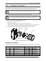
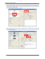
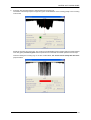
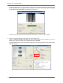
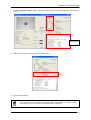
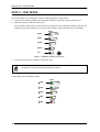
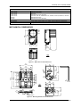
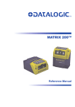
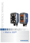
Matrix 400™
QUICK REFERENCE GUIDE
1
3
2
4
5
2
7
10
2
8
9
6
Figure A
1
Device Class Label
6
HMI X-PRESS™ Interface
2
Mounting Holes (12)
7
"POWER ON" LED
3
Lens Cover
8
Power - Serial Interfaces - I/O Connector
4
Lens (separate accessory)
9
Ethernet Connector (Ethernet Models Only)
5
Internal Illuminator (separate accessory)
10 Ethernet Connection LED
(Ethernet Models Only)
NOTE
This manual illustrates a Stand Alone application. For other types of installations, such as ID-NET™,
Pass-Through, Multiplexer Layout, etc. and for a complete reader configuration using the VisiSet™
configuration program, refer to the Matrix 400™ Reference Manual available on the CD. This manual
is also downloadable from the Web at www.automation.datalogic.com/matrix400.
MATRIX 400™ QUICK GUIDE
UPDATES AND LANGUAGE AVAILABILITY
UK/US
The latest drivers and documentation updates for this product are available on Internet.
Log on to: www.automation.datalogic.com
I
Su Internet sono disponibili le versioni aggiornate di driver e documentazione di questo prodotto.
Collegarsi a: www.automation.datalogic.com
F
Les versions mises à jour de drivers et documentation de ce produit sont disponibles sur Internet.
Cliquez sur : www.automation.datalogic.com
D
Im Internet finden Sie die aktuellsten Versionen der Treiber und Dokumentation von diesem Produkt.
Adresse : www.automation.datalogic.com
E
En Internet están disponibles las versiones actualizadas de los drivers y documentación de este producto.
Dirección Internet : www.automation.datalogic.com
SERVICES AND SUPPORT
Datalogic provides several services as well as technical support through its website. Log on to
www.automation.datalogic.com and click on the links indicated for further information including:
•
PRODUCTS
Search through the links to arrive at your product page where you can download specific Manuals and
Software & Utilities including:
- VisiSet™ a utility program, which allows device configuration using a PC. It provides RS232 and Ethernet
interface configuration.
•
SERVICES & SUPPORT
- Datalogic Services - Warranty Extensions and Maintenance Agreements
- Authorised Repair Centres
•
CONTACT US
E-mail form and listing of Datalogic Subsidiaries
2
MATRIX 400™ QUICK GUIDE
STEP 1 – ASSEMBLE THE READER
The first step to perform is to assemble the accessories that make up the Matrix 400™ reader. The lens and
either an internal or an external illuminator must be used. This procedure shows an internal illuminator.
Matrix 400™ must be disconnected from the power supply during this procedure.
CAUTION
1.
In a dust-free environment, remove the Matrix 400™ Lens Cover by unscrewing it.
Do not touch the sensor aperture, lens glass or lens cover glass. These areas must be kept
clean. Avoid any abrasive substances that might damage these surfaces during cleaning.
CAUTION
2.
Remove the sensor protection label by pulling it off of the base.
3.
Mount the lens by screwing it tightly onto the base.
4.
If using an internal illuminator:
5.
a.
Mount the 4 internal illuminator spacers into the holes provided on the base.
b.
Align and mount the Illuminator board tightly onto the spacers using the 4 screws provided in the
illuminator package. The spacers are positioned asymmetrically to avoid incorrect alignment.
To keep dust and dirt off of the lens during mounting, temporarily replace the lens cover.
Locking Knobs
Internal
Illuminator
Lens Cover
Illuminator Spacers
Figure 1 – Assembling Matrix 400™ Accessories
REQUIRED ACCESSORIES
The following table shows the correct lens/illuminator combinations to be used for Matrix 400™ imager assembly.
Lenses
93ACC1793
LNS-1006
93ACC1794
LNS-1109
6 mm C-Mount Lens
(only for Matrix 400 600-0x0 models)
9 mm C-Mount Lens
93ACC1795
LNS-1112
12.5 mm C-Mount Lens
93ACC1796
LNS-1116
16 mm C-Mount Lens
93ACC1797
LNS-1125
25 mm C-Mount Lens
93ACC1798
93ACC1799
LNS-1135
LNS-1150
35 mm C-Mount Lens
50 mm C-Mount Lens
Internal Illuminators
93A401020
93A401022
93A401020
93A401022
93A401020
93A401022
93A401019
93A401021
93A401019
93A401021
93A401024
93A401024
LT-002
LT-004
LT-002
LT-004
LT-002
LT-004
LT-001
LT-003
LT-001
LT-003
LT-006
LT-006
Red Wide Angle
White Wide Angle
Red Wide Angle
White Wide Angle
Red Wide Angle
White Wide Angle
Red Narrow Angle
White Narrow Angle
Red Narrow Angle
White Narrow Angle
Red Super Narrow Angle
Red Super Narrow Angle
3
MATRIX 400™ QUICK GUIDE
STEP 2 – CONNECT THE SYSTEM
To connect the system in a Stand Alone configuration, you need the hardware indicated in Figure 2. In this layout
the data is transmitted to the Host on the main serial interface. Data can also be transmitted on the RS232
auxiliary interface independently from the main interface selection. When One Shot or Phase Mode Operating
mode is used, the reader is activated by an External Trigger (photoelectric sensor) when the object enters its
reading zone.
PG 6000
CBX
Main Interface
CAB-MS01
Matrix 400™
Host
P.S.*
I/O, AUX
* External Trigger or Presence Sensor
(for One Shot or Phase Mode)
Figure 2 – Matrix 400™ in Stand Alone Layout
CBX100/CBX500 Pinout for Matrix 400™
The table below gives the pinout of the CBX100/CBX500 terminal block connectors. Use this pinout when the
Matrix 400™ reader is connected by means of the CBX100/CBX500:
CBX100/500 Terminal Block Connectors
Vdc
GND
Earth
+V
I1A
I1B
-V
+V
I2A
I2B
-V
Shield
Power
Power Supply Input Voltage +
Power Supply Input Voltage Protection Earth Ground
+V
-V
O1+
O1O2+
O2-
Inputs
Power Source – External Trigger
External Trigger A (polarity insensitive)
External Trigger B (polarity insensitive)
TX
Power Reference – External Trigger
RX
Power Source – Inputs
SGND
Input 2 A (polarity insensitive)
Input 2 B (polarity insensitive)
REF
Power Reference – Inputs
ID+
Shield
IDNetwork Cable Shield
Main Interface
RS232
RS485 Full-Duplex
TX
TX+
RTS
TX*RX+
RX
*RXCTS
SGND
SGND
Outputs
Power Source - Outputs
Power Reference - Outputs
Output 1 +
Output 1 Output 2 +
Output 2 Auxiliary Interface
Auxiliary Interface TX
Auxiliary Interface RX
Auxiliary Interface Reference
ID-NET™
Network Reference
ID-NET™ network +
ID-NET™ network -
RS485 Half-Duplex
RTX+
RTX-
SGND
* Do not leave floating, see Reference Manual for connection details.
CAUTION
4
Do not connect GND, SGND and REF to different (external) ground references. GND, SGND
and REF are internally connected through filtering circuitry which can be permanently
damaged if subjected to voltage drops over 0.8 Vdc.
MATRIX 400™ QUICK GUIDE
19-pin Connector Pinout for Matrix 400™
The table below gives the pinout of the 19-pin M16 male connector for connection to the power supply and
input/output signals. Use this pinout when the Matrix 400™ reader is connected by means of the 19-pin
connector:
Figure 3 - 19-pin M16 Male Connector
19-pin M16 male connector pinout
Pin
A
L
K
B
C
D
E
H
F
G
I
S
O
R
P
Name
Function
Vdc
GND
CHASSIS
I1A
I1B
I2A
I2B
O1+
O1O2+
O2RX
TX
ID+
ID-
Power supply input voltage +
Power supply input voltage Cable shield internally connected by capacitor to the chassis
External Trigger A (polarity insensitive)
External Trigger B (polarity insensitive)
Input 2 A (polarity insensitive)
Input 2 B (polarity insensitive)
Output 1 +
Output 1 Output 2 +
Output 2 Auxiliary RS232 RX
Auxiliary RS232 TX
ID-NET™ network +
ID-NET™ network RS485
RS485
RS232
Full-Duplex
Half-Duplex
TX
TX+
RTX+
*RX+
RX
RTS
TXRTX*RXCTS
Pin
Name
M
U
N
T
MAIN INTERFACE
(SW SELECTABLE)
* Do not leave floating, see Reference Manual for connection details.
5
MATRIX 400™ QUICK GUIDE
STEP 3 – MOUNT AND POSITION THE READER
1.
To mount the Matrix 400™, use the mounting brackets to obtain the most suitable position for the reader.
Two of the most common mounting configurations are shown in the figures below. Other mounting solutions
are provided in the Matrix 400™ Reference Manual.
Pitch
Tilt
Figure 4 –Positioning with Mounting Bracket (Back)
Pitch
Skew
Figure 5 –Positioning with Mounting Bracket (Side)
2.
When mounting the Matrix 400™ take into consideration these three ideal label position angles: Pitch or Skew 10°
to 20° and Tilt 0°, although the reader can read a code at any tilt angle.
P
T
S
Minimize
Assure at least 10°
Minimize
Figure 6 – Pitch, Skew and Tilt Angles
3.
Refer to the Optical Accessory Selection table in the Appendix of this Quick Reference Guide for FOV
calculation and minimum distance requirements according to the base/lens combination used for your
application.
NOTE
6
Rapid Configuration of the Matrix 400™ reader can be made either through the X-PRESS™
interface (steps 4-6) which requires no PC connection, or by using the VisiSet™ Setup Wizard
(steps 7-8). Select the procedure according to your needs.
MATRIX 400™ QUICK GUIDE
STEP 4 – FOCUS THE READER
Matrix 400™ provides a built-in tool called Blue Diamonds™ to aid focusing the reader. The Blue Diamonds™ are
accessed through the X-PRESS™ Interface.
1.
Remove the lens cover in order to focus the reader.
2.
Prepare the correct accessory lens for your application:
a.
Loosen the two Locking Knobs on the lens.
b.
Adjust the Focus ring to the "Far position" and the Diaphragm ring to the "F4" number setting which is
the preferred setting for installation.
1
3.
Power the reader on. During the reader startup (reset or restart phase), all the LEDs blink for one second. On
the connector side of the reader near the cable, the “POWER ON” LED (blue) indicates the reader is correctly
powered.
4.
Enter the Focus function by pressing and holding the X-PRESS™ push button until the Focus LED is on.
5.
Release the button to enter the Focus function. The Blue Diamonds™ turn on.
The procedure is as follows:
a.
b.
READY
Adjust the Focus ring towards the "Near position" until the Blue
Diamonds™ are perfectly in focus, see Figure 8.
green
At long focal distances a "skew" angle may cause a noticeable
difference in focus between the two diamonds, in this case select
the best possible focus (both diamonds slightly out of focus).
Tighten the Focus Locking Knob.
green
Tighten the Diaphragm Locking Knob.
yellow
LEARN
GOOD
SETUP
TRIGGER
yellow
FOCUS
COM
TEST
STATUS
red
Figure 7 – X-PRESS™ Interface:
Focus Function
If necessary you can use the Fine Focusing Tool in the VisiSet™ Setup Wizard for fine focusing.
See Step 8.
NOTE
FOV
Blue Diamond™
in focus
Figure 8 – Focus Function Using Blue Diamonds™
6.
Exit the Focus function by pressing the X-PRESS™ push button once. The Blue Diamonds™ turn off.
7.
Replace the lens cover, screwing it tightly to the base.
1
For far reading distances, the Diaphragm ring can be set to values between F2 and F4 to increase image lighting and Blue
Diamond™ visibility.
7
MATRIX 400™ QUICK GUIDE
STEP 5 – CALIBRATE IMAGE DENSITY
In order to function correctly to the fullest extent of its capabilities, Matrix 400™ must acquire information
regarding image density or PPI (pixels per inch). This calibration takes place through the X-PRESS™ Interface
and the Grade A Barcode Test Chart included in the package. This procedure is necessary for the first time
installation, if the lens type is changed or if the focal distance is changed.
LOCATE
1. Enter the Focus function by pressing and holding the X-PRESS™ push
button until the Focus LED is on.
2. Release the button to enter the Focus function. The Blue Diamonds™
turn on.
3. From the Grade A Barcode Test Chart, select the longest code whose
length fits between the two Blue Diamonds™. Rotate the code 90
degrees and position the code at the center of the FOV (equidistant
from the Blue Diamonds™).
READY
green
LEARN
GOOD
green
SETUP
TRIGGER
yellow
FOCUS
COM
yellow
TEST
STATUS
red
Figure 9 – X-PRESS™ Interface:
Locate Function
4. Exit the Focus function by pressing the X-PRESS™ push button once.
The Blue Diamonds™ turn off.
SETUP
5. Enter the Setup function by pressing and holding the X-PRESS™ push
button until the Setup LED is on.
6. Release the button to enter the Setup function. The Setup LED will blink
until the procedure is completed.
The Setup procedure ends when the Image Acquisition parameters are
successfully saved in the reader memory, the Setup LED will remain on
continuously and Matrix 400™ emits 3 high pitched beeps.
If the calibration cannot be reached after a timeout of about 5 (five)
seconds Matrix 400™ will exit without saving the parameters to memory,
the Setup LED will not remain on continuously but it will just stop blinking.
In this case Matrix 400™ emits a long low pitched beep.
7. Exit the Setup function by pressing the X-PRESS™ push button once.
READY
green
LEARN
GOOD
green
SETUP
TRIGGER
yellow
FOCUS
COM
yellow
TEST
STATUS
red
Figure 10 – X-PRESS™ Interface:
Setup Function
LEARN
8. Enter the Learn function by pressing and holding the X-PRESS™ push
button until the Learn LED is on.
9. Release the button to enter the Learn function. The Learn LED will blink
until the procedure is completed.
The Learn procedure ends when the Image Density value is successfully
saved in the reader memory, the Learn LED will remain on continuously,
the Green Spot is activated and Matrix 400™ emits 3 high pitched beeps.
If the calibration cannot be reached after a timeout of about 3 (three)
minutes Matrix 400™ will exit without saving the parameters to memory,
the Learn LED will not remain on continuously but it will just stop blinking.
In this case Matrix 400™ emits a long low pitched beep.
10. Exit the Setup function by pressing the X-PRESS™ push button once.
8
READY
green
LEARN
GOOD
green
SETUP
TRIGGER
yellow
FOCUS
COM
yellow
TEST
STATUS
red
Figure 11 – X-PRESS™ Interface:
Learn Function
MATRIX 400™ QUICK GUIDE
STEP 6 – X-PRESS™ CONFIGURATION
Once Matrix 400™ has calibrated image density, you can configure it for optimal code reading relative to your
application. This configuration can be performed either through the X-PRESS™ Interface or the VisiSet™
configuration program.
LOCATE
READY
1. Enter the Focus function by pressing and holding the X-PRESS™ push
button until the Focus LED is on.
green
2. Release the button to enter the Focus function. The Blue Diamonds™
turn on.
green
3. Select a code from your application. Position the code at the center of
the FOV (equidistant from the Blue Diamonds™).
yellow
4. Exit the Focus function by pressing the X-PRESS™ push button once.
The Blue Diamonds™ turn off.
yellow
LEARN
GOOD
SETUP
TRIGGER
FOCUS
COM
TEST
STATUS
red
Figure 12 – X-PRESS™
Interface: Locate Function
SETUP
5. Enter the Setup function by pressing and holding the X-PRESS™ push
button until the Setup LED is on.
6. Release the button to enter the Setup function. The Setup LED will blink
until the procedure is completed.
The Setup procedure ends when the Image Acquisition parameters are
successfully saved in the reader memory, the Setup LED will remain on
continuously and Matrix 400™ emits 3 high pitched beeps.
If the calibration cannot be reached after a timeout of about 5 (five) seconds
Matrix 400™ will exit without saving the parameters to memory, the Setup
LED will not remain on continuously but it will just stop blinking. In this case
Matrix 400™ emits a long low pitched beep.
7. Exit the Setup function by pressing the X-PRESS™ push button once.
READY
green
LEARN
GOOD
green
SETUP
TRIGGER
yellow
FOCUS
COM
yellow
TEST
STATUS
red
Figure 13 – X-PRESS™
Interface: Setup Function
LEARN
8. Enter the Learn function by pressing and holding the X-PRESS™ push
button until the Learn LED is on.
9. Release the button to enter the Learn function. The Learn LED will blink
until the procedure is completed.
The Learn procedure ends when the Image Processing and Decoding
parameters are successfully saved in the reader memory, the Learn LED
will remain on continuously, the Green Spot is activated and Matrix 400™
emits 3 high pitched beeps.
If the calibration cannot be reached after a timeout of about 3 (three)
minutes Matrix 400™ will exit without saving the parameters to memory,
the Learn LED will not remain on continuously but it will just stop blinking. In
this case Matrix 400™ emits a long low pitched beep.
10. Exit the Setup function by pressing the X-PRESS™ push button once.
READY
green
LEARN
GOOD
green
SETUP
TRIGGER
yellow
FOCUS
COM
yellow
TEST
STATUS
red
Figure 14 – X-PRESS™
Interface: Learn Function
If you have used this procedure to configure Matrix 400™ go to step 9.
9
MATRIX 400™ QUICK GUIDE
STEP 7 – INSTALLING VISISET™ CONFIGURATION PROGRAM
VisiSet™ is a Datalogic reader configuration tool providing several important advantages:
•
Setup Wizard for rapid configuration and new users;
•
Defined configuration directly stored in the reader;
•
Communication protocol independent from the physical interface allowing to consider the reader as a remote
object to be configured and monitored.
To install VisiSet™, turn on the PC that will be used for the configuration, running Windows 98, 2000/NT, XP
or Vista, then insert the VisiSet™ CD-ROM, wait for the CD to autorun and follow the installation procedure.
This configuration procedure assumes a laptop computer, running VisiSet™, is connected to the reader's auxiliary
port.
After installing and running the VisiSet™ software program the following window appears:
Figure 15 - VisiSet™ Opening Window
Set the communication parameters from the "Options" menu. Then select "Connect", the following window
appears:
Figure 16 - VisiSet™ Main Window After Connection
10
MATRIX 400™ QUICK GUIDE
STEP 8 – CONFIGURATION USING SETUP WIZARD
The Setup Wizard option is advised for rapid configuration or for new users. It allows reader configuration in a few
easy steps.
1.
Select the Setup Wizard button from the Main menu.
2.
Remove the lens cover in order to focus the reader and loosen the two Locking Knobs on the lens.
1
Adjust the Focus ring to the "Far position" and the Diaphragm ring to the "F4" number setting which is the
preferred setting for installation.
Place the Grade A Barcode Test Chart in front of the reader at the correct reading distance (see step 3 and
the Optical Accessory Selection table in the Appendix of this Quick Reference Guide).
1
For far reading distances, the Diaphragm ring can be set to values between F2 and F4 to increase image lighting.
11
MATRIX 400™ QUICK GUIDE
3.
Press the "Positioning" button. The reader continuously acquires images and gives visual feedback in the
view image window. Select the largest code from the chart that completely fits into the view image window.
Move the reader (or code) to center it. The code must be aligned across the X-axis reference line at the
center of the FOV. See figure below.
Press the Positioning button again to stop positioning.
3
4.
Select a Calibration Mode choice and press the "Calibrate" button. The reader flashes once acquiring the
image and auto determines the best exposure and gain settings. If the code symbology is enabled by default,
the code will also be decoded.
4
5
12
MATRIX 400™ QUICK GUIDE
5.
Press the "Fine Focusing" button to activate the Fine Focusing Tool.
The reader continuously acquires images and gives visual feedback on the focusing quality in the Focusing
Tool window.
Rotate the Focusing ring on the lens. The Current Focus Quality Bar (green) together with the vertical optimal
focus line (green) increase together until the optimal focus is reached; the vertical optimal focus line stops.
Continue rotating the Focusing ring on the lens a little farther; the Current Focus Quality Bar decreases
(red) see below.
13
MATRIX 400™ QUICK GUIDE
Rotate the Focusing ring in the opposite direction. The Current Focus Quality Bar (green) increases towards
the vertical optimal focus line (green) until the optimal focus is reached; the Current Focus Quality Bar
touches the vertical optimal focus line (indicating the best focus).
Tighten the Locking Knobs on the lens and press the "Close" button to return to the Setup Wizard.
6.
Select a Code Setting Mode choice and press the "Code Setting" button.
Using the Grade A Barcode Test Chart, this step performs image density calibration in order for
Matrix 400™ to function correctly and to the fullest extent of its capabilities.
The Setup Result section of the Setup Wizard window shows the code type results and the image density
calibration settings.
6
14
MATRIX 400™ QUICK GUIDE
7.
Place the application specific code in front of the reader at the same reading distance and repeat steps 3,
4, and 6.
3
4
6
Setup Result
8.
Select a Saving Options choice and press the "Save" button.
9.
Close the Setup Wizard.
If your application has been configured using the VisiSet™ Setup Wizard, your reader is ready.
If necessary you can use VisiSet™ for advanced reader configuration.
NOTE
15
MATRIX 400™ QUICK GUIDE
STEP 9 – TEST MODE
Use a code suitable to your application to test the reading performance of the system.
1.
Enter the Test function by pressing and holding the X-PRESS™ push button until the Test LED is on.
2.
Release the button to enter the Test function.
Once entered, the Bar Graph on the five LEDs is activated and if the reader starts reading codes the BarGraph shows the Good Read Rate. In case of no read condition, only the STATUS LED is on and blinks.
READY
green
LEARN
GOOD
green
SETUP
TRIGGER
yellow
FOCUS
COM
yellow
TEST
STATUS
red
Figure 17 – X-PRESS™ Interface: Test Function
3.
To exit the Test, press the X-PRESS™ push button once.
By default, the Test exits automatically after three minutes.
NOTE
The Bar Graph has the following meaning:
READY
≥ 95%
LEARN
GOOD
≥ 75%
SETUP
TRIGGER
≥ 60%
FOCUS
COM
≥ 40%
TEST
STATUS
≥ 20%
16
MATRIX 400™ QUICK GUIDE
ADVANCED READER CONFIGURATION
For further details on advanced product configuration, refer to the complete Reference Manual on the installation
CD-ROM or downloadable from the web site through this link: www.automation.datalogic.com/matrix400.
The following are alternative or advanced reader configuration methods:
ADVANCED CONFIGURATION USING VISISET™
Advanced configuration can be performed through the VisiSet™ program by selecting Device> Get Configuration
From Temporary Memory to open the Parameter Setup window in off-line mode. Advanced configuration is
addressed to expert users being able to complete a detailed reader configuration. The desired parameters can be
defined in the various folders of the Parameter Setup window and then sent to the reader memory (either
Temporary or Permanent):
Figure 18 - VisiSet™ Parameter Setup Window
HOST MODE PROGRAMMING
The reader can also be configured from a host computer using the Host Mode programming procedure, by
commands via the serial interface. See the Host Mode Programming file on the CD-ROM.
ALTERNATIVE LAYOUTS
If you need to install an Ethernet network, ID-NET™ network, Fieldbus network, Pass-Through network,
Multiplexer network or an RS232 Master/Slave refer to the Matrix 400™ Reference Manual.
CODE QUALITY VERIFICATION
Matrix 400™ can be used as a Code Quality Verifier according to the ISO/IEC 15415, ISO/IEC 15416, AS9132,
and AIM DPM Standards. For more details see the Matrix 400™ Code Quality Verifier Solution manual on the
CD-ROM.
17
MATRIX 400™ QUICK GUIDE
APPENDIX
X-PRESS™ is the intuitive Human Machine Interface designed to improve ease of installation and maintenance.
Status and diagnostic information are clearly presented by means of the five colored LEDs, whereas the single
push button gives immediate access to the following relevant functions:
•
Learn to self-detect and auto-configure for reading unknown codes
•
Setup to perform Exposure Time and Gain calibration.
•
Focus/Locate to turn on the Blue Diamonds™ to aid focusing and positioning.
•
Test with bar graph visualization to check static reading performance
In normal operating mode the colors and meaning of the five LEDs are illustrated in the following table:
READY (green)
GOOD (green)
TRIGGER (yellow)
COM (yellow)
STATUS (red)
This LED indicates the device is ready to operate.
This LED confirms successful reading.
This LED indicates the status of the reading phase.
This LED indicates active communication on main serial port.
This LED indicates a NO READ result.
During the reader startup (reset or restart phase), all the LEDs blink for one second.
On the connector side of the reader near the cable, the blue POWER ON LED indicates the reader is correctly
powered.
For Ethernet models, on the connector side of the reader near the Ethernet connector, the orange ETHERNET
NETWORK PRESENCE LED indicates the on-board Ethernet network connection.
On-board Ethernet
Network LED
Power LED
Figure 19 – Power and On-Board Ethernet Network LEDs
18
MATRIX 400™ QUICK GUIDE
OPTICAL ACCESSORY SELECTION
Referring to Figure 20 and the formula below, use the data in the following table to calculate the FOV for your
application.
Viewing Angle
Horizontal
Viewing Angle
Vertical
Viewing Angle
Diagonal
Min Focus Distance
mm
400 400-0x0
(SXGA)
LNS-1109 9 mm
LNS-1112 12.5 mm
LNS-1116 16 mm
LNS-1125 25 mm
LNS-1135 35 mm
LNS-1150 50 mm
48.5°
37°
28.5°
18.5°
13°
9°
39.5°
30°
23°
15°
10,5°
7°
60°
46.5°
36°
23.5°
16.5°
11.5°
85
85
85
135
235
500
400 600-0x0
(UXGA)
LNS-1006 6 mm
LNS-1109 9 mm
LNS-1112 12.5 mm
LNS-1116 16 mm
LNS-1125 25 mm
LNS-1135 35 mm
LNS-1150 50 mm
59.5°
40.5°
31°
24°
15°
11°
7.5°
46.5°
31°
23.5°
18°
11.5°
8.5°
5.5°
71°
49.5°
38°
30°
19°
13.5°
9.5°
85
85
85
85
135
235
500
Model
Lens
The viewing angle has a tolerance of ± 1° depending on the focus distance.
FOVx = 2 (d + 35 mm) tan (αx/2)
where:
FOVx = horizontal, vertical or diagonal FOV
αx = horizontal, vertical or diagonal viewing angles.
d = focus distance
35 mm
d
α
FOV
plane
Figure 20 – Reading Distance References
Example:
The FOV for a Matrix 400 600-0x0 base using the 16 mm lens at a focus distance of 200 mm is:
FOVH = 2 [(200 mm + 35 mm) tan (24°/2)] = 100 mm
FOVV = 2 [(200 mm + 35 mm) tan (18°/2)] = 74 mm
19
MATRIX 400™ QUICK GUIDE
TECHNICAL FEATURES
ELECTRICAL FEATURES
Power
Supply Voltage
Consumption
Communication Interfaces
Main
- RS232
- RS485 full-duplex
- RS485 half-duplex
Auxiliary - RS232
ID-NET™
Ethernet (Ethernet Models only)
Inputs
Input 1(External Trigger) and Input 2
Outputs
Output 1 and Output 2
2400 to 115200 bit/s
2400 to 115200 bit/s
2400 to 115200 bit/s
2400 to 115200 bit/s
Up to 1MBaud
10/100 Mbit/s
OPTICAL FEATURES
400 4xx-xxx models
Image Sensor
Image Format
Frame Rate
Pitch
Tilt
Lighting System
LED Safety Class
CMOS
CCD
SXGA (1280x1024)
UXGA (1600x1200)
27 frames/sec.
15 frames/sec.
± 35°
0° - 360°
Internal or External Illuminator (accessories)
Class 1 to EN60825-1
10 to 30 Vdc
0.8 to 0.27 A, 8 W max.; 0.5 to 0.17 A, 5 W typical
Opto-coupled and polarity insensitive
Opto-coupled
400 6xx-xxx models
ENVIRONMENTAL FEATURES
Operating Temperature
Storage Temperature
Max. Humidity
Vibration Resistance
EN 60068-2-6
Bump Resistance
EN 60068-2-29
Shock Resistance
EN 60068-2-27
Protection Class
0 to 50 °C (32 to 122 °F) *
-20 to 70 °C (-4 to 158 °F)
90% non condensing
14 mm @ 2 to 10 Hz; 1.5 mm @ 13 to 55 Hz;
2 g @ 70 to 200 Hz; 2 hours on each axis
30g; 6 ms;
5000 shocks on each axis
30g; 11 ms;
3 shocks on each axis
IP67 **
PHYSICAL FEATURES
Dimensions
Weight
Material
123 x 60.5 x 87 mm (4.85 x 2.38 x 3.43 in.) with lens cover
482 g. (17 oz.) with lens and internal illuminator
Aluminium
SOFTWARE FEATURES
Readable Code Symbologies
1-D and stacked
• PDF417 Standard and Micro PDF417
• Code 128 (EAN 128)
• Code 39 (Standard and Full ASCII)
• Interleaved 2 of 5
• Codabar
• Code 93
• Pharmacode
• EAN-8/13 - UPC-A/E
(including Addon 2 and Addon 5)
• GS1 DataBar (RSS) Family
• Composite Symbologies
Operating Mode
Configuration Methods
Parameter Storage
2-D
• Data Matrix ECC 200
(Standard and Direct Marking)
• QR Code
(Standard and Direct Marking)
• MAXICODE
• Aztec Code
• Microglyph
(this symbology requires an
activation procedure – contact your
local Datalogic Automation
distributor for details)
•
•
•
•
•
•
•
•
POSTAL
Australia Post
Royal Mail 4 State Customer
Kix Code
Japan Post
PLANET
POSTNET
POSTNET (+BB)
Intelligent Mail
ONE SHOT, CONTINUOUS, PHASE MODE
X-PRESS™ Human Machine Interface
Windows™ based SW (VisiSet™) via serial or Ethernet link
Serial Host Mode Programming sequences
Permanent memory (Flash)
* high ambient temperature applications should use metal mounting bracket for heat dissipation
** when correctly connected to IP67 cables with seals and the Lens Cover is correctly mounted.
20
MATRIX 400™ QUICK GUIDE
CODE QUALITY VERIFICATION
Standard
ISO/IEC 16022
ISO/IEC 18004
ISO/IEC 15415
ISO/IEC 15416
AS9132A
AIM DPM
Supported Symbologies
Data Matrix ECC 200
QR Code
Data Matrix ECC 200, QR Code
Code 128, Code 39, Interleaved 2 of 5, Codabar, Code 93, EAN-8/13, UPC-A/E
Data Matrix ECC 200
Data Matrix ECC 200, QR Code
USER INTERFACE
LED Indicators
Keypad Button
Power, Ready, Good; Trigger; Com, Status, (Ethernet Network); (Green Spot)
Configurable via VisiSet™
109
[4.29]
123.2
[4.85]
30.25
[1.19]
MECHANICAL DIMENSIONS
60.5
[2.38]
18
[0.71]
41.5
[1.63]
87
[3.43]
mm
[in]
Ø61
[Ø2.40]
Figure 21 – Matrix 400™ Overall Dimensions
12.5 12.5 12.5 12.5
[0.49] [0.49] [0.49] [0.49]
34
[1.34]
=
50
[1.97]
4.2
[0.17]
Ø4
[Ø0 .2
.17
]
=
40
[1.57]
3
[0.12]
=
41.5
[1.63]
26.5
[1.04]
M4
[0.16] N°7
4.2
[0.17]
7
[0.28]
4.3
[0.17]
[0 4 .2
.1
7]
4.3
[0.17]
45°
4
[0.16]
45°
25
Ø8. 2]
.3
[Ø0
mm
[in]
70
[2.76]
12.5
[0.49]
34
[1.34]
=
=
15° 15°
=
72.5
[2.85]
83.5
[3.29]
=
8.5
]
[0.33
=
12.5
[0.49]
61
[2.40]
50
[1.97]
Figure 22 – Mounting Brackets Overall Dimensions
21
MATRIX 400™ QUICK GUIDE
PATENTS
This product is covered by one or more of the following patents:
U.S. patents: 6,512,218 B1; 6,616,039 B1; 6,808,114 B1; 6,997,385 B2; 7,102,116 B2; 7,282,688 B2
European patents: 999,514 B1; 1,014,292 B1; 1,128,315 B1.
Additional patents pending.
COMPLIANCE
EMC COMPLIANCE
In order to meet the EMC requirements:
•
connect reader chassis to the plant earth ground by means of a flat copper braid shorter than 100 mm;
•
connect pin "Earth" of the CBX connection box to a good Earth Ground;
POWER SUPPLY
This product is intended to be installed by Qualified Personnel only.
This product is intended to be connected to a UL Listed Computer which supplies power directly to the reader or a
UL Listed Direct Plug-in Power Unit marked LPS or “Class 2”, rated 10 to 30 V, minimum 1 A.
CE COMPLIANCE
Warning: This is a Class A product. In a domestic environment this product may cause radio interference in
which case the user may be required to take adequate measures.
FCC COMPLIANCE
Modifications or changes to this equipment without the expressed written approval of Datalogic could void the
authority to use the equipment.
This device complies with PART 15 of the FCC Rules. Operation is subject to the following two conditions: (1)
This device may not cause harmful interference, and (2) this device must accept any interference received,
including interference which may cause undesired operation.
This equipment has been tested and found to comply with the limits for a Class A digital device, pursuant to part
15 of the FCC Rules. These limits are designed to provide reasonable protection against harmful interference
when the equipment is operated in a commercial environment. This equipment generates, uses, and can radiate
radio frequency energy and, if not installed and used in accordance with the instruction manual, may cause
harmful interference to radio communications. Operation of this equipment in a residential area is likely to cause
harmful interference in which case the user will be required to correct the interference at his own expense.
22
MATRIX 400™ QUICK GUIDE
SERIAL NUMBER REFERENCES
Place the replicate, lens, illuminator and filter serial number labels here for reference. Some of this information
can also be written in the Reader Information configuration parameters in the Miscellaneous folder in VisiSet™.
Serial Numbers
Matrix 400™
Lens
Illuminator
Filter
23
DECLARATION OF CONFORMITY
08
Datalogic Automation S.r.l.
Via S. Vitalino 13
40012 - Lippo di Calderara
Bologna - Italy
dichiara che
declares that the
déclare que le
bescheinigt, daß das Gerät
declare que el
Matrix 4XX YYY-ZZZ
e tutti i suoi modelli
and all its models
et tous ses modèles
und seine Modelle
y todos sus modelos
sono conformi alle Direttive del Consiglio Europeo sottoelencate:
are in conformity with the requirements of the European Council Directives listed below:
sont conformes aux spécifications des Directives de l'Union Européenne ci-dessous:
der nachstehend angeführten Direktiven des Europäischen Rats:
cumple con los requisitos de las Directivas del Consejo Europeo, según la lista siguiente:
89/336/EEC EMC Directive
e
and
et
und
y
92/31/EEC, 93/68/EEC
emendamenti successivi
further amendments
ses successifs amendements
späteren Abänderungen
succesivas enmiendas
Basate sulle legislazioni degli Stati membri in relazione alla compatibilità elettromagnetica ed alla sicurezza dei prodotti.
On the approximation of the laws of Member States relating to electromagnetic compatibility and product safety.
Basée sur la législation des Etats membres relative à la compatibilité électromagnétique et à la sécurité des produits.
Über die Annäherung der Gesetze der Mitgliedsstaaten in bezug auf elektromagnetische Verträglichkeit und Produktsicherheit
entsprechen.
Basado en la aproximación de las leyes de los Países Miembros respecto a la compatibilidad electromagnética y las Medidas
de seguridad relativas al producto.
Questa dichiarazione è basata sulla conformità dei prodotti alle norme seguenti:
This declaration is based upon compliance of the products to the following standards:
Cette déclaration repose sur la conformité des produits aux normes suivantes:
Diese Erklärung basiert darauf, daß das Produkt den folgenden Normen entspricht:
Esta declaración se basa en el cumplimiento de los productos con las siguientes normas:
EN 55022 (Class A ITE), September 1998:
INFORMATION TECHNOLOGY EQUIPMENT
RADIO DISTURBANCE CHARACTERISTICS
LIMITS AND METHODS OF MEASUREMENTS
EN 61000-6-2, September 2005:
ELECTROMAGNETIC COMPATIBILITY (EMC)
PART 6-2: GENERIC STANDARDS - IMMUNITY FOR INDUSTRIAL
ENVIRONMENTS
Lippo di Calderara, January 29th, 2008
Lorenzo Girotti
Product & Process Quality Manager
821001353 (Rev. C)