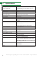
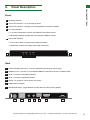
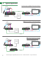
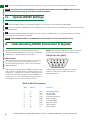
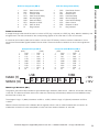
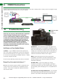
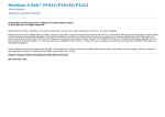
1
WyreStorm Display Receiver
Solutions
RX-70-PP
Low Profile 70m/230ft HDBaseT™ Display
Receiver with Bidirectional IR Control & RS232
Instruction Manual
Thank you for choosing this WyreStorm product.
Please read these instructions carefully before installing to avoid complications later.
Technical Support: [email protected] US: +1 866 677 0053 EU: +44 (0) 1793 230 343
1
CONTENTS AND INTRODUCTION
Contents
1
Introduction
2
Features
3
Safety Precautions
4
Package Contents
5
Specification
6
Panel Descriptions
7
Connection & Operation
i. Pro Plus PoH Cabling Guide / Typical Application
ii. RJ45 Termination & Distance
iii. Initial Connection
iv. IR/RS232 Control Connection
8
RS232 - Understanding RS232 Connection and Signals
9
Updating RS232 Settings
10 RS232 Connection
11 Troubleshooting
12 FAQs
13 Maintenance
14 Product Service
15 Mail In Service
16 Warranty
i. Warranty Limits and Exclusions
17 Installation Notes
2
1.
Introduction
Thin is the new thick.
As part of the WyreStorm Pro Plus range, the slim-line
RX-70-PP Display Receiver offers HDBaseT Class B
distribution when connected to a WyreStorm HDBaseT
transmission device such as matrix switcher, transmitter
or AMP-001-010 digital audio amplifier.
Supporting a feature set including 70m/230ft
transmissions of Full HD 1080p@60Hz video with 36bit
deep color, HD audio and discrete bidirectional IR control
IR, the RX-70-PP also features RS232 with switchable
selection for firmware updates or third party control
serial control, all along a single Cat5e/6 cable to display
devices. Pushing chassis design to the limit, the RX-70-PP offers
an incredibly low-profile for a greatly reduced form factor
behind the screen for even more convenience and ease of
installation at the display zone.
Featuring threaded bushings that allow use of both
standard and locking DC power plugs for improved
connection options, the RX-70-PP also includes LED
indication for power supply, signal status to show
established connection to display, transmission link and
HDCP confirmation to illustrate the presence of encryption
within a signal.
WyreStorm Pro Plus HDBaseT products offer flexibility
combined with an ease of use and cost-efficiency to
provide solutions where reliabile HD transmission and
control over distance is required whether in a residential or
commercial setting.
For further information on this product and other
WyreStorm ranges, visit our website or download our
latest product guide. www.wyrestorm.com
Technical Support: [email protected] US: +1 866 677 0053 EU: +44 (0) 1793 230 343
2.• Fully 3D
Features
compatible – Frame sequential 3D (Blu-ray) and
• 2k resolution supported.
interlaced stereoscopic 3D (satellite broadcasts etc.)
extender sets.
3. Safety Precautions
3. Safety Precautions
• Supports
all high definition
and including
• Display
Receivers
capableresolutions
of 1080p up
HDtovideo
1080p
video formats.
@60Hz
andand
HDstandard
multichannel
audio transmissions up to
WARNING
WARNING
70m/230ft
• RS232 under
port. perfect conditions*
reduce
theofrisk
fire, electric
To To
reduce
the risk
fire,ofelectric
shock shock
• Low profile chassis of 15mm / 0.59” for easier, more
or
product
damage:
or product damage:
• Choose from 6 switching modes – infrared remote control, front
convenient installations behind screens at display zones.
panel buttons, local IR, IR call-back, LAN and RS232.
• Transmits discrete wide-band two-way IR control signal
1. Do not expose this apparatus to rain, moisture, sprays,
• Simple
switching
remotesignal
controlover
included,
whichCat5e/6.
can also be
together
within
the HDMI
a single
1. Do not
this apparatus
rain,
dripsexpose
or splashes
and ensuretothat
nomoisture,
objects containing
learned
into
a
universal
remote
handset
to
allow
the
control
of
• Robust Class B HDBaseT transmission technology
sprays,
drips
splashes
ensure including
that no cups,
liquids
are or
placed
on theand
apparatus,
multiple devices from one handset.
for more
affordable HD distribution and control whilst
objects
containing
liquids are placed on the
glasses
and vases.
retaining
the trademark
HDBaseT
stability
and control
resistance
apparatus, including cups, glasses and vases.
• Fully compatible
for integration
with market
leading
systems.
2. Do not place this unit in a confined space such as
to electrostatic
and environmental interference compared
• 4 x IR 3.5mm mini-jack ports for each output to link IR from
enclosed shelving, cabinets or bookshelves. Ensure the
to conventional
UTP
transmission.
2. Do not
this unitventilated.
in a confined space such as
control system
to control
display
unit place
is adequately
• Supports all high definition resolutions: 1080p, 1080i,
enclosed shelving, cabinets or bookshelves.
• Additional infrared extension port for longer IR connections
3.
To prevent
of electric
shock or fire hazard due to
720p
with screen refresh rates of 24Hz, 30Hz, 50Hz and
Ensure
the unitthe
is risk
adequately
ventilated.
overheating, do not cover the unit or obstruct ventilation
60Hz.
• HDMI v.1.3
openings with material, newspaper, cardboard or
• HDMI
v1.4 with full 3D compatibility with frame packing/ 3. To prevent the risk of electric shock or fire hazard
• Supports 24Bit Colour depth
anything that may restrict airflow into the unit.
sequential (Blu-Ray) and interlaced stereoscopic (satellite/
due to overheating, do not cover the unit or
• Signalling
rate of 6.75 Gbps
4.
Do notventilation
install near
external heat
cable
broadcasts)
obstruct
openings
with sources
material,such as
radiators,cardboard
heat registers,
boilers orthat
anymay
device
that
• Central
RS232
compatible
switchable
RS232
for
newspaper,
or
anything
restrict
• Pack comes complete with 1 x 4x4 Matrix with 19” rack
produces heat such as amplifiers or computers and do
firmware
updates
or IR
third
party with
control
with open
source
airflow into the unit.
brackets,
4 x 40m
receivers
mounting
brackets,
IR
not place near sources of naked flame.
receivers,
emitters and
a Matrixfor
remote
control
handset.
integration
protocols
available
market
leading
control
Unplug
apparatus
from power
during
systems
- check
website
for listing
4. 5.
Do not
install
near external
heat supply
sources
suchlightening
as
Additional
features
included
on the RX-1UTP-IR-40
stormsheat
or when
unusedboilers
for long
of time.
• Receivers cascadable up to 7 times within a single
radiators,
registers,
orperiods
any device
that
• Transmits one-way signal together with the HDMI signal over a
output
zone (7 x 70m/230ft) using another Class B
produces
such as
amplifiers
or computers
and
6.
Protectheat
the power
cable
from being
walked on, pinched
single Cat5e/6/7 cable.
HDBaseT transmission device.
do not
place near
sources
of naked at
flame.
or restricted
in any
way, especially
plug connections.
• Receivers
capable
of 1080p transmissions
up to 40m (131ft)
• Fully
supports
3D applications
(frame-packing/
7. Only use attachments/accessories specified by the
under ideal
conditions*
sequential
– Blu-ray
and Interlaced Stereoscopic –
5. Unplug apparatus from power supply during
manufacturer.
Satellite/cable
broadcasts)
lightening storms or when unused for long periods
• For even greater
control and fine tuning, each receiver features
8.
Units contain non-servicable parts - Refer all servicing to
• Supports
36bit Deep
Colour range for optimising the
of time.
a fully adjustable
EQ distance
qualified service personnel.
• Cable
termination
follows IEEE-568B standards
transmission
signal.
• HDCP compliant
6. Protect the power cable from being walked on,
• Automatically adjusts
feedback,
equalization
and
pinched
or restricted
in (0)
any1793
way,230
especially
at plug
Technical
Support:
[email protected]
US: +866
677 0053
EU: +44
343
4
amplification of signal for easy installation.
connections.
• Threaded bushings on receivers allow use of both
standard and locking DC power plugs
7. Only use attachments/accessories specified by the
• LED indication for visual power supply to receiver,
manufacturer.
signal status to show established connection to display,
HDBaseT link to matrix and HDCP confirmation to
8. Units contain non-servicable parts - Refer all
illustrate the presence of encryption within a signal
servicing to qualified service personnel.
*Perfect transmission conditions - cable run within
specified distance range of product, no electrical
interference, the use of straight cable runs with no
bends or kinks and no patch panels or wall outlets
used. Please be advised that the presence of any of
these factors in your installation may compromise
bandwidth and signal strength.
For longer transmission distance, Ethernet pass- through,
to enable devices with 4k resolution or for 48bit Deep
Colour compatibility, please see our range of full HDBaseT
receivers and extender sets.
4.
Package Contents
• 1 x WyreStorm RX-70-PP Display Receiver
• 1 x Receiver mounting brackets (pair)
• 1 x 12V/1.5A DC power supply
• 1 x Wide-band IR TX Emitter
• 1 x Wide-band IR RX Receiver (30-50KHz)
• 1 x 3.5mm Phoenix male Connector (3 pin)
*Digital manual downloadable from
www.wyrestorm.com
Technical Support: [email protected] US: +1 866 677 0053 EU: +44 (0) 1793 230 343
3
FEATURES, SAFETY PRECAUTIONS AND PACKAGE CONTENTS
• Reads and copies EDID from connected devices with additional
EDID configuration through customisable DIP switch settings if
necessary.
SPECIFICATIONS
5.
Specifications
Operating Temperature Range
32°F to 95°F (0°C to 35°C) 10% to 90%, non-condensing
Operating Humidity Range
Storage Temperature -4°F to 140°F (-20°C to 70°C) 10% to
90%, non-condensing
Input
1 x HDBT IN
Input Signal Type
HDBT 2.0
Bandwith Signalling Rate
6.75Gbps
Input Resolution Support
1080p/1080i/720p/576p/480p/576i/480i
Input Video Signal
0.5 - 1.2 V p-p
Input DDC Signal
5 volts p-p (TTL)
Output
1 x HDMI OUT
Output Signal Type
HDMI v1.4 with full 3D compatibility with frame packing/
sequential (Blu-ray) and interlaced stereoscopic (satellite/cable
broadcasts)
Output Resolution Support
1080p/1080i/720p/576p/480p/576i/480i
Video Format Supported
VESA: 640x480, 800x600, 1024x768, 1280x1024, 1600x1200,
1920x1080 1920x1200
DTV/HDTV: 480i/567i/480p/567p/720p/1080i/1080p
Audio Format Supported
DTS-HD, Dolby True HD
Video Impedance
100 Ω
Maximum Pixel Clock
148.5 MHz (1080p)
Power Supply
12V/1.5A DC
Power Consumption
7.6 Watts (Each)
BTU Rating (British Thermal Unit)
25.9
ESD Protection
±8kV (Air-gap discharge)
±4kV (Contact discharge)
Surge Protection
IEC 61000-4-4 (EFT) 40A (5/50ns);
IEC 61000-4-5 (Lightning) 25A (8/20μs)
Cat5e/6 Cable Specifications
70m/230ft: 1080p, 60Hz, 36bit deep colour
35m/114: 1080p, 60Hz, 48bit deep colour / 1080p, 60Hz, 3D
Note: HDBaseT certified, straight-through T568B standard
cables strongly recommended
Dimensions
135mm / 5.3” (W)
15mm / 0.6” (H)
74mm / 2.9” (D)
Weight
240g / 8.46oz
4
Technical Support: [email protected] US: +1 866 677 0053 EU: +44 (0) 1793 230 343
Panel Description
PANEL DESCRIPTIONS
6.
Front
1
Mounting Brackets
2
Power LED indication - Lit for receiver powered
3
Status LED indication - Blinking to show established connection to display
4
Link LED indication
i. Lit to show link between receiver and HDBaseT transmission device
ii. Off/blinking suggests possible link issue between HDBaseT devices
5
HDCP LED indication
i. Lit to confirm HDCP encrypted video being transmitted
ii. Off/blinking no HDCP encrypted video being transmitted
Power Status
1
2
3
Link
4
HDCP
1
5
Rear
1
12VDC lockable power input - connects standard and locking DC power plugs
2
HDBaseT Input - connects to a compatible HDBaseT transmission device via Cat5e/6 cable
3
IR RX - connects to supplied IR Receiver
4
IR TX - connects to supplied IR Emitter
5
RS232 - for update or control system connection
6
HDMI Output to display
7
RS232 Mode select - toggle between Control (Normal) and firmware (Update)
Tx Rx
1
2
3
4
5
Normal
6
Update
7
Technical Support: [email protected] US: +1 866 677 0053 EU: +44 (0) 1793 230 343
5
TYPICAL APPLICATION
7i.
Typical Application
Pro Plus matrix as HDBaseT Transmission Device
Blu-ray
Display Output
hdmi
ir rx
ir tx
cat5e/6
70m/230ft
rs232
hdmi
WyreStorm 8x8
Pro Plus Matrix
rs232
Control
System
ir tx
ir rx
HDBaseT Transmitter as Transmission Device
Blu Ray
Display Output
hdmi
ir Tx
rs232
ir rx
hdmi
Control
System
rs232
ir tx
ir rx
cat5e/6
70m/230ft
AMP-001-010 Digital Audio Amplifier
HDBaseT Transmission Device
Blu Ray
Display Output
Control
System
hdmi
ir Tx
rs232
ir rx
hdmi
rs232
ir tx
cat5e/6
70m/230ft
ir rx
cat5e/6
70m/230ft
6
Technical Support: [email protected] US: +1 866 677 0053 EU: +44 (0) 1793 230 343
RJ45 Termination and Cat5e/6 Cable Distance
Cat5e Wiring Guide
The quality of termination
for every RJ45 is
essential. Poor terminations leads to intermittent
performance and longer install times.
7iii.
Cat5e/6 Cable Performance Guide
RX-70-PP
0m
10m
20m
30m
40m
50m
60m
70m
80m
90m
100m
0ft
32ft
65ft
98ft
131ft
164ft
197ft
230ft
262ft
295ft
328ft
Initial Connection
1
Firmly connect an HDMI input (such as Blu-Ray, games console, satellite/cable, media server etc.) to a HDBaseT
transmission device (such as a WyreStorm HDBaseT transmitter, AMP-001-010 digital amplifier or Pro Plus matrix
solution.)
2
Connect a good quality, well terminated Cat5e/6 cable of no more than 70m/230ft in length between the UTP/
HDBaseT output of the transmission device to the HDBT IN of the RX-70-PP
Attention 70m/230ft is the maximum recommended transmission distance for this classification of
HDBaseT equipment and denotes perfect transmission conditions - including straight cable runs with no
electrical interference, bends, kinks, patch panels or wall outlets. If any of the above are a factor in your
installation, transmission range may be affected – take care to avoid where possible.
3
Connect the HDMI sink (LED /Plasma display / digital projector) to the HDMI OUT of the RX-70-PP receiver.
NOTE We strongly recommend using the supplied mounting brackets to secure the receiver. Any sudden movement of
devices can lead to loss of picture/sound if connections become loose or strained,
resulting in unnecessary service call backs.
4
If daisy-chaining receivers, repeat process for all RX-70-PP units installed from your transmission devices.
7iv.
IR/RS232 Control Connection
1
For two way control of connected sources and displays from either location, connect IR transmitters to the IR TX
ports of the HDBaseT Transmitter devices and RX-70-PP.
2
Insert IR receivers into IR RX ports of the HDBaseT Receiver devices and matrix.
3
If using an RS232-based control system, insert cables into the RS232 ports of devices to enable RS232 control.
4
Ensure IR TX transmitters are firmly attached over IR sensors of devices to be controlled.
NOTE If unsure of positioning, IR sensors can be located on devices by shining a flashlight onto the facia
of the device - the IR sensor should be identifiable as a small round sensor behind the panel. Consult your
device manufacturer handbook if difficulties are experienced.
Technical Support: [email protected] US: +1 866 677 0053 EU: +44 (0) 1793 230 343
7
RJ45 TERMINATION AND CAT5E/6 CABLE DISTANCE, INITIAL CONNECTION AND IR/RS232 CONTROL CONNECTION
7ii.
5
Ensure IR RX receivers are positioned in clear line of sight to the remote handset used to control them.
UPDATE RS232 SETTINGS AND UNDERSTANDING RS232 CONNECTION & SIGNALS
NOTE For serial control via the RS232 port on the RX-70-PP please ensure the MODE switch is set to
Normal. The Update setting is reserved for firmware updates.
7v.
1
Update RS232 Settings
Move the MODE switch to the Update setting for the receiver to enter Firmware Update Mode
2
Connect a Serial-to-USB cable from the RS232 port of the RX-70-PP to a computer and run VS010 RX Firmware
Update batch file.
3
Once the update has been completed, be sure to return the MODE switch to the Normal position for RS232
control signal transmission to be passed.
NOTE Connect RS232 cables to the RS232 port of the Receiver to form one extension cable.
8.
Understanding RS232 Connection & Signals
RS-232C, EIA RS-232, or simply RS-232, refers to
the same standard defined by the Electronic Industries
Association in 1969 for serial communication.
DTE and DCE
DTE stands for Data Terminal Equipment. A computer
or control system is DTE and connects to Data
Communication Equipment, or DCE such as an Amp,
Matrix or Modem.
DTE equipment typically feature a Male Connector, while
DCE contains a Female Connector, although that is not
always true - a simple way to confirm is to measure Pin
3 and Pin 5 of a DB-9 Connector with a Volt Meter. If a
voltage of -3V to -15V is achieved, the device is DTE. If
the voltage is on Pin 2, then the device is DCE.
NOTE: The result for a DB-25 Connector is reversed
(Please refer to DB-9 to DB-25 conversion table)
RS-232 Pin outs (DB-9)
1 2 3 4 5
6 7 8 9
A male DB-9 connector viewed from the front.
Reverse or back view of male connector for
Female Connector.
DB-9 to DB-25 Conversion
8
DB-9
DB-25
1
2
3
4
5
6
7
8
9
8
3
2
20
7
6
4
5
22 Function
DCD
RxD
TxD
DTR
GND
DSR
RTS
CTS
RI
Data Carrier Detect
Receive Data
Transmit Data
Data Terminal Ready
Ground (Signal)
Data Set Ready
Request to Send
Clear to Send
Ring Indicator
Technical Support: [email protected] US: +1 866 677 0053 EU: +44 (0) 1793 230 343
1
2
3
4
5
6
7
8
9
DCD
RxD
TxD
DTR
GND
DSR
RTS
CTS
RI
Data Carrier Detect
Receive Data
Transmit Data
Data Terminal Ready
Ground (Signal)
Data Set Ready
Request to Send
Clear to Send
Ring Indicator
DCE Pin Assignment (DB-9)
1
2
3
4
5
6
7
8
9
DCD
TxD
RxD
DSR
GND
DTR
CTS
RTS
RI
Data Carrier Detect
Transmit Data
Receive Data
Data Set Ready
Ground (Signal)
Data Terminal Ready
Clear to Send
Request to Send
Ring Indicator
RS232 Connections
A straight-through cable should be used to connect a DTE (e.g. computer) to a DCE (e.g. Amp, Matrix or Modem), with
all signals from one side connected to the corresponding signals on the other side in a one-to-one basis.
A crossover (null-modem) cable can be used to connect two DTE directly, without a modem in between to cross
transmit and receive data signals between the two sides. There are numerous variations on how control signals are
wired:
1
2
3
4
5
6
7
8
9
Straight-through (DB-9
(DTE) (DCE)
DCD ------- DCD 1
RxD ------- TxD
2
TxD
------- RxD 3
DTR ------- DSR 4
GND ------- GND 5
DSR ------- DTR 6
RTS ------- CTS 7
CTS ------- RTS 8
RI
------- RI
9
Mark (1)
space (0)
LSB
start
Crossover (Null-Modern) (DB-9
(DTE) (DCE)
1
DCD ------- DCD 1
2
RxD ------- TxD
3
3
TxD
------- RxD 2
4
DTR ------- DSR 6
5
GND ------- GND 5
6
DSR ------- DTR 4
7
RTS ------- CTS 8
8
CTS ------- RTS 7
9
RI
RI
9
MSB
0 1 2 3 4 5 6 7
stop
-12v
+12v
RS232 Logic Waveform (8N1)
The graphic (p.8 bottom left) illustrates a typical RS232 logic waveform (Data format: 1 Start bit, 8 Data bits, No Parity,
1 Stop bit). The data transmission starts with a Start bit, followed by the data bits (LSB sent first and MSB sent last),
and ends with a “Stop” bit.
The voltage of Logic “1” (Mark) is between -3VDC to -15VDC, while the Logic “0” (Space) is between +3VDC to
+15VDC.
RS232 connects the Ground of 2 different devices together, which is the so-called “Unbalanced” connection. An
unbalanced connection is more susceptible to noise, and has a distance limitation of 15m/49ft.
Technical Support: [email protected] US: +1 866 677 0053 EU: +44 (0) 1793 230 343
9
UNDERSTANDING RS232 CONNECTION & SIGNALS
DTE Pin Assignment (DB-9)
RS232 CONNECTION AND TROUBLESHOOTING
9.
RS232 Connection
To allow serial commands sent from transmitting device to be sent to display device, simply connect a straight-through
RS232 cable between the RX-70-PP and your display.
Blu-ray
Display Output
Control
System
ir rx
hdmi
ir tx
cat5e/6
70m/230ft
Control
System
rs232
hdmi
WyreStorm 8x8
Pro Plus Matrix
ir tx
rs232
ir rx
CONTROL SYSTEM
10.
Troubleshooting
Generally, the majority of HD distribution installation
issues are either caused by minor connection
errors, communication problems between devices,
or when the transmission of high signal bandwidth
is attempted using insufficient cable. Should you
encounter any technical difficulties when installing
and configuring the matrix, we are confident
solutions can be found by working through the
following troubleshooting checklist before seeking
alternative technical support.
No Picture or Poor Quality Picture
1) Power – is your HDBaseT transmission device and
RX-70-PP receiver powered with correct LED indication?
All units should have their own power source connected
ie. 12v for most 70m/230ft for HDBaseT devices – Please
use power supplies included.
Are all sources definitely powered and firmly connected?
2) If possible, always use test equipment prior to
installation and to troubleshoot any problems.
3) Check sink device supports HDCP, is switched to the
correct source inout mode and is compatible with the
receiver - if any issue is suspected, replace sink device
with another model.
10
WyreStorm Install
Test Kit
TT-HDMI-KIT
4) Distance – Is the cable too long for the signal to be
transmitted effectively? The HDBaseT classification used
within the transmitters and receivers allow transmission of
1080p up to 70m/230ft so make sure the cable distance
matches the project requirements and is well within the
maximum transmission distance of the signal.
Note: If approaching the limits of the transmission
capabilities, transmission should be extended by using
another extender set to ensure the signal reaches its
destination effectively.
5) Cable Joins – Joins in the cable run or RJ45
connectors can impact on signal strength, resulting in
reduced transmission that may manifest itself in incorrect
picture quality, picture dropping out or a complete lack of
picture
6) Cable Choice and Signal Reduction – Are stranded
patch leads being used as interconnects between patch
panels or wall outlets? CCA (Copper Clad aluminium)
Technical Support: [email protected] US: +1 866 677 0053 EU: +44 (0) 1793 230 343
7) Correct connection – It may seem obvious but
double check all UTP, HDMI, power and IR cables are
connected to the correct ports.
Note: Even a fraction off can be the difference between
aperfect picture and a blank screen. Double check all
connections are firmly made in the correct ports.
8) Cable wired to 568B standard? Is the cable wired
and terminated correctly and are those terminations
connected to the correct ports? Incorrect wiring and
termination will result in unstable operation or a blank
screen.
9) Electrical interference – HDBaseT is less susceptible
to interference compared to regular transmissions but
the location of cables and devices should be considered
- could any form of interference be generated? If so,
attempt to remove the source of electrical interference
or move the cable run to decrease the effects of the
interference.
10) Is a picture achieved when connecting the
source directly to the display? If not then the problem
could lie with the input or output device rather than the
means of distribution i.e. the cable, receiver or matrix
itself.
11) HDMI lead condition and quality – HDMI cables
and connectors are delicate and can be damaged much
easier than component or coax cable. Furthermore,
lead quality varies dramatically, particularly in lower price
brackets. Swap HDMI leads and check operation –
damage to or quality of your leads could be the problem.
If in doubt, swap them over. Always take care inserting
and extracting your HDMI from matrix ports so as not to
damage the connectors or ports.
12) Picture speckles/HD ‘noise’ – represents a poorly
established signal that may be caused by poor quality or
excessive HDMI cable lengths. Try swapping the display
adaptors from a location that is functioning properly or
swapping the outputs of the matrix switch used.
If the problem remains on the same screen this may be
caused by a connection problem between matrix and
display – turn off all equipment and swap the signal
carrying cables at both ends to ascertain if the cable or
termination is at fault.
HD Noise (NO image) may be an HDCP Issue between
the source and display but poor cabling can also cause
this due to poor communication.
13) Blu-ray: 3D – is the equipment used 3D enabled/
compatible? Is a 3D disc being played in a 3D enabled
Blu-ray player or through a compatible AV receiver?
14) Colour distortion – a pink or green screen indicates
an incompatibility between colour spacing formats – the
commonly used RGB or YUV used by older displays.
Some sources allow switching between RGB and YUV
which may solve any colour problems. If not, try changing
the HDMI cable between the source and the matrix to rule
out defective cabling.
No Sound or Poor Quality Audio
Audio is transmitted within the video signal – there is no
separate audio track – so generally a problem with sound
will be accompanied by a problem with picture. However,
if technical issues with audio are experienced, the cause
is typically communication between sources, displays
and/or AV receiver settings.
1) Have specific speaker sets or zones been
enabled? Some AV receivers allow individual speaker
selections assigned to specific zones in the set up so
check the speakers used are fully connected to the
amplifier and correctly assigned within the system set up.
It may be an EDID issue in that the source reads the audio
EDID from the display and only requests two channel
audio and EDID copy from the AVR may be required or
use an embedded EDID in the AMP or Matrix.
Note: If problems are experienced when an AV receiver is
used, the cause is usually the settings of the AVR itself.
Refer to the AVR manufacturer’s guidelines on the correct
settings to use for your requirements.
2) Consistency of audio output between devices – Is
there any discrepancy between the audio output of the
source, the audio or zonal settings of the AV receiver and
the speaker configuration used needed for successful
audio replication? If outputting 7.1, make sure all devices
connected are also outputting 7.1
Note: Occasionally with some sources, the device settings
allow the specification of audio output through a TV or an
HDMI port. If using an AV receiver, check the HDMI output
option is selected.
Technical Support: [email protected] US: +1 866 677 0053 EU: +44 (0) 1793 230 343
11
TROUBLESHOOTING
cables being used? These can reduce transmission
rates by up to 40% – we recommend solid core straight
through with minimum connections used wherever
possible.
TROUBLESHOOTING AND FAQS
3) Do all the local sources work through the AV
receiver?
Check the operation of each source individually.
Bandwidth
1) If using a graphics-based source (such as a PC/Mac/
media server), make sure the source resolution is set to
a maximum of 1080p, 50Hz. Higher resolutions available
for graphics-based systems require higher bandwidth
that may affect transmission of signals as well as
incompatibility with devices.
IR
1) Check emitters at the IR TX transmitter end
and receivers at the IR RX receiver end – are they
connected to the correct ports on the matrix and display
receiver.
2) Is the emitter correctly positioned on the source?
Fix the emitter directly over the infrared sensor of the
source and attach using the adhesive backing.
Note: Locate the infrared source sensor by using a
flashlight to find the sensor within the facia of the source
display. If necessary, secure the emitter over the sensor
with a small amount of contact adhesive.
3) Is the remote handset powered and sending a
signal?
Note: IR is invisible to the naked eye, so use a digital
camera/ phone camera to check the remote signal – point
the camera at the remote control when pressing a button.
The remote transmitter can be seen flashing to indicate a
signal being sent. Replace batteries if flashing is not seen
on the digital camera screen.
4) IR dropout issues can be due to exterior influences
emitting infrared radiation that can interrupt IR signals.
Ensure emitters and receivers are away from the following
causes of IR interference.
• Direct sunlight, Fluorescent lighting (on cold start up)
• Halogen lighting
• Plasma screens
5) UTP Termination Issues – ensure cables and RJ45
terminations are correct and in good condition at
both transmitter and receiver ends to see if control is
established. If so, a possible re-termination of the cable
could remedy the problem.
6) Are WyreStorm emitters and receivers being used?
12
The use of third party products/magic eyes may not be
compatible. Always use WyreStorm components included
with your purchase or check compatibility of third party
control systems with your WyreStorm dealer.
7) If problems persist, swap out the IR emitters and
receivers to rule out faults with the units themselves. Use
emitters you know are fully operational to test working
condition.
8) Reactivate the IR call-back function on your matrix
and swap IR ports on the matrix to rule out a fault with
thematrix or connection ports.
9) Should IR remain unresponsive, turn off and disconnect
all cables from the matrix and reconnect zones one at a
time to assess if one location in particular is the problem.
If so, run new cables directly to the display – if this fixes
the problem, it is likely that electromagnetic interference /
damage to the cable somewhere along the run is causing
the IR signal to drop out. Investigate and remove EM
interference from the run or replace damaged UTP cable.
11.
FAQs
Cat5e or 6?
While our equipment is tested and graded to Cat 5e
cable standard; tests have shown that better results
are achieved when using Cat6 cable. The lower AWG
(American Wire Gauge) uses thicker copper cores ensure
better signal transfer/Transmission rates. Newly installed
cabling should always conform to Part P Regulation and
BS 7671 (17th Edition), and should be terminated to 568B
standard.
Can I use a single Cat 5e/Cat 6 cable?
Although conventional transmission used to be
considered two Cat5e cables for video, audio and control,
HDBaseT transmission only requires a single cable.
All features found with dual cable transmissions are
supported with HDBaseT, with addition of RS232 serial
control, Power and Ethernet passed along a single
Cat5e/6/7, depending on feature set/model of product
How far can the signal travel?
Under perfect transmission conditions WyreStorm
HDBaseT receivers will operate at 50m, 70m or 100m
(@1080p) depending on the model used.
Perfect conditions denotes no electrical interference,
straight cable runs with no bends or kinks and no patch
Technical Support: [email protected] US: +1 866 677 0053 EU: +44 (0) 1793 230 343
Should a cable run approach the upper limit of the
receiver capabilities, the signal can be boosted by
connecting to an HDBaseT AMP-001-010 digital audio
amplifier/receiver act as an in-line repeater up to 7 times
up to 490m/1607ft.
What about 3D?
The RX-70-PP, all of our matrix switches and the majority
of our extender products will pass-through a 3D Blu-ray
signal.
How do I control the sources?
All of our HDMI distribution products support IR passthrough from point-to-point extender sets to AMP and
HDBaseT matrices. Most of the range now supports
wideband IR meaning it is compatible with any IR device
available on the market. Our PP and HDBaseT matrix
range (Cat 5e/Cat6) has IR pass-through from each of the
outputs and has discrete IR outputs at the switch end,
meaning you can have multiple identical sources yet the
IR would be routed only to the applicable source.
Do I need power at the TV end?
Yes. This product requires its own 12v local/mains power
at display zones to operate.
WyreStorm PoH enabled devices require no power supply
at the TV end by drawing power from a PoH matrix or
PoH transmitter. See www.wyrestorm.com for details on
our PoH range.
Are WyreStorm products compatible with HDMI 1.4?
HDMI 1.4 refers to a list of ‘features’ that a device is
capable of supporting, including Ethernet channel, return
audio channel, 3Detc. Due to the continuously evolving
nature of the technology, HDMI Licensing LLC have now
decided to simplify terminology by testing and referring to
cable in terms of STANDARD or HIGH-SPEED rather than
in generations 1.3, 1.4 etc.
• STANDARD (or “category 1”) HDMI cables perform
at speeds of 75Mhz or up to 6.75Gbps, which is the
equivalent to a 720p/1080i signal – These HDMI cables
are NOT recommended.
• All WyreStorm equipment support HIGH-SPEED
(or “category 2”) HDMI cables that have been tested
to perform at speeds of 340Mhz or up to 10.2Gbps,
which is the highest bandwidth currently utilised over
an HDMI cable and can successfully handle 1080p
signals including those at increased colour depths and/
or increased refresh rates from the Source. High-Speed
cables are also able to accommodate higher resolution
displays, such as WQXGA cinema monitors (resolution of
2560 x 1600).
FAQS
panels or wall outlets. If some of the above are factors in
your installation then signal strength and bandwidth can
be compromised.
What about screens with different resolution
capabilities?
When sending a signal point to point a TV will
communicate it’s capabilities to the source, then the
source will output a suitable signal that compatible (i.e.
1080p Stereo audio). If you were to use a matrix switch
with three 1080p screens and one 1080i screen, the
resultant image would be1080i across all screens. The
matrix switches do not scale per output but instead
negotiate with the source a signal that all screens are
capable of supporting.
How does the Trasnmission device handle HDCP?
HDCP (High Definition Copyright Protection) is a feature
built in to HDMI devices to prevent theft of or illegal
distribution of HD content. Unlike competing products,
WyreStorm equipment are legal and comply with HDCP
regulations.
They do this by assigning a “key” to any display
connected to the device. HDCP “keys” are assigned to a
display when connected to a HDMI device normally. This
doesn’t change when connecting to an extender, receiver
or matrix switch; rather keys are duplicated or more are
assigned.
I can get 1080i but not 1080p at a TV location
Firstly ensure that both the source is capable of outputting
1080p and that the TV is Full HD 1080p screen. If this is
the case then the AMP, 70 metre receiver or PP Matrix
may require EDID management setting up using the DIP
switches. This useful feature provides a successful “send
and receive” to ensure swift and stable EDID negotiation
between the source and display. See Troubleshooting
section for more tips on problem solving.
I cannot get a signal from my A/V receiver along a
Cat 5e extender set
Check to ensure that the A/V Receiver isn’t adding CEC
(HDMI Control Protocol) to the outgoing signal, this can
sometimes have an effect on the HDMI signal.
Technical Support: [email protected] US: +1 866 677 0053 EU: +44 (0) 1793 230 343
13
MAINTENANCE, PRODUCT SERVICE, MAIL-IN-SERVICE, WARRANTY AND WARRANTY LIMITS AND EXCLUSIONS
12.
Maintenance
Clean this unit with a soft, dry cloth only. Never use
alcohol, paint thinner or other harsh chemicals.
13.
Product Service
1. Damage requiring service: This unit should be
serviced by a qualified service personnel if:
• The DC power supply or AC adaptor has been
damaged.
• Objects or liquid have gotten into the unit.
• The unit has been exposed to rain.
• The unit does not operate normally or exhibits a marked
change in performance.
• The unit has been dropped or the cabinet damaged.
2. Servicing Personnel: Do not attempt to service
the unit beyond that described in these operating
instructions. Refer all other servicing to authorised
servicing personnel.
3. Replacement Parts: When parts need replacing,
ensure parts approved by the manufacturer are used
– either those specified by the manufacturer or parts
possessing the same characteristics as the original parts.
Be aware – unauthorised substitutes may result in fire,
electric shock, or other hazards and will invalidate your
warranty.
4. Safety Check: After repairs or service, ask the
service personnel to perform safety checks to confirm
the unit is in proper working condition.When shipping the
unit, carefully pack and send it prepaid, with adequate
insurance and preferably in the original packaging. Please
include a document or letter detailing the reason for
return and include a daytime telephone number and/or
email address where you can be contacted.
14.
Mail-in-service
If repair is required during the limited warranty period,
the purchaser will be required to provide a sales receipt
or other proof of purchase, indicating date and location
of purchase as well as the price paid for the product.
The customer will be charged for the repair of any unit
received unless such information is provided.
14
15i.
Warranty
Should you feel your product does not function
adequately due to defects in materials or workmanship,
WyreStorm (referred to as “the warrantor”) will, for the
length of the period indicated below (starting from the
original date of purchase) either:
a) Repair the product with new or refurbished parts.
or
b) Replace it with a new or refurbished product.
Limited warranty period:
All WyreStorm products are covered by a 3 year PARTS
and LABOUR warranty. During this period there will be no
charge for unit repair, replacement of unit components or
replacement of product if necessary.
The decision to repair or replace will be made by the
warrantor. The purchaser must mail-in the product during
the warranty period. This limited warranty only covers the
product purchased as new and is extended to the original
purchaser only. It is non-transferable to subsequent
owners, even during the warranty period.
A purchase receipt or other proof of original purchase
date is required for the limited warranty service.
15ii.
Warranty Limits and
Exclusions
1. This Limited Warranty ONLY COVERS failures due
to defects in materials or workmanship and DOES
NOT COVER normal wear and tear or cosmetic
damage.
The limited warranty also DOES NOT COVER damage
that occurs in shipment or failures caused by products
not supplied by the warrantor, failures resulting from
accident, misuse, abuse, neglect, mishandling,
misapplication, alteration, incorrect installation, set-up
adjustment, implementation of/to consumer controls,
improper maintenance, power line surge, lightening
damage, modification, service by anyone other than
a manufacturer-approved service centre or factoryauthorised personnel, or damage attributable to acts of
God.
2. There are no express warranties except as listed
under “limited warranty coverage.” The warrantor
Technical Support: [email protected] US: +1 866 677 0053 EU: +44 (0) 1793 230 343
INSTALLATION NOTES
is not liable for incidental or consequential damage
resulting from the use of this product or arising out
of any breach of this warranty.
For example: damages for lost time, the cost of having a
person/persons remove or re-install previously installed
equipment, travel to and from service location, loss of or
damage to media, images, data or other recorded/stored
content. The items listed here are not exclusive, but are
for illustration only.
Parts and service not covered by this limited warranty
are not the responsibility of the warrantor and should be
considered the responsibility of the individual.
17.
Installation Notes
Technical Support: [email protected] US: +1 866 677 0053 EU: +44 (0) 1793 230 343
15
www.wyrestorm.com
WyreStorm Offices
US Office: 6991 Appling Farms Parkway, Suite 104, Memphis, TN 38133
Tel: + 901 384 3575 Fax: + 901 384 3574
Unit 22, Ergo Business Park, Swindon, Wiltshire, SN3 3JW UK
Tel: +44 (0) 1793 230 343 Fax: +44 (0) 1793 230 583
WyreStorm Technical Support
US: +86 6677 0053
UK:- +44 (0) 1793 238 338
Email: [email protected]
WyreStorm Technologies reserve the right to change physical appearance or technical specification of this product at any time.
Visit www.wyrestorm.com for the latest information on products..