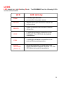
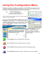
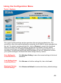
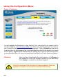
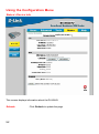
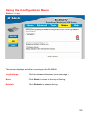
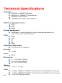
1
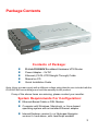
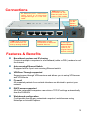
D-Link DI-804HV
Broadband Hardware T M
VPN Router
Manual
Building Networks for People
02212003
Contents
Package Contents ................................................................................ 3
Introduction........................................................................................... 4
Getting Started ................................................................................... 10
Using the Configuration Menu ............................................................. 11
Networking Basics ............................................................................. 57
Reset to Factory Default Settings ........................................................ 83
Technical Specifications ..................................................................... 84
Contacting Technical Support ............................................................. 85
Warranty and Registration ................................................................... 86
2
Package Contents
Contents of Package:
n
n
n
n
n
D-Link DI-804HV Broadband Hardware VPN Router
Power Adapter – 5V DC
Ethernet (CAT5-UTP/Straight-Through) Cable
Manual on CD
Quick Installation Guide
Note: Using a power supply with a different voltage rating than the one included with the
DI-804HV will cause damage and void the warranty for this product.
If any of the above items are missing, please contact your reseller.
System Requirements For Configuration:
n Ethernet-Based Cable or DSL Modem
n Computer with Windows, Macintosh, or Linux-based
operating system with an installed Ethernet adapter
n Internet Explorer version 6.x or Netscape Navigator
version 6.x and above, with JavaScript enabled
3
Introduction
The D-Link DI-804HV is a 4-port Broadband Router with Virtual Private Network
(VPN) functionality. It provides a complete solution for Internet surfing and office
resources sharing. It is an ideal way to extend the reach and number of
computers connected to your network.
After completing the steps outlined in the Quick Installation Guide (included in
your package) you will have the ability to share information and resources.
The DI-804HV is compatible with most popular operating systems, including
Macintosh, Linux and Windows, and can be integrated into a large network.
4
Connections
All Ethernet ports auto-sense
c able ty pes t o ac c omodate
str aight- through or c ross-over
cable.
WAN port is the
connection for the
Ethernet cable to the
Cable or DSL modem
Receptor
for the
Power
Adapt er
COM port provides
serial connection for
dial-up analog modem.
LAN ports provide
connections to Ethernetenabled devices.
Pressing the
Reset Button
restores the
router to its
original factory
default settings.
Features & Benefits
n
Broadband modem and IP sharing
Connects multiple computers to a broadband (cable or DSL) modem to surf
the Internet
n
Auto-sensing Ethernet Switch
Equipped with a 4-port auto-sensing Ethernet switch
n
VPN Pass-Through supported
Supports pass-through VPN sessions and allows you to setup VPN server
and VPN clients
n
Firewall
All unwanted packets from outside intruders are blocked to protect your
network
n
DHCP server supported
All of the networked computers can retrieve TCP/IP settings automatically
from the DI-804HV
n
Web-based configuration
Configurable through any networked computer’s web browser using
Netscape or Internet Explorer
5
Features & Benefits continued
n
Access Control supported
Allows you to assign different access rights for different users
n
Packet filter supported
Packet Filter allows you to control access to a network by analyzing the
incoming and outgoing packets and letting them pass or halting them based
on the IP address of the source and destination.
n
Virtual Server supported
Enables you to expose WWW, FTP and other services on your LAN to be
accessible to Internet users.
n
User-Definable Application Sensing Tunnel
User can define the attributes to support special applications requiring
multiple connections, like Internet gaming, video conferencing, Internet
telephony and so on. The DI-804HV can sense the application type and
open a multi-port tunnel for it.
n
DMZ Host supported
Allows a networked computer to be fully exposed to the Internet; this
function is used when the special “application-sensing tunnel feature” is
insufficient to allow an application to function correctly
Introduction to Broadband
Router Technology
A router is a device that forwards data packets from a source to a destination. Routers
forward data packets using IP addresses and not a MAC address. A router will forward
data from the Internet to a particular computer on your LAN.
The information that makes up the Internet gets moved around using routers. When
you click on a link on a web page, you send a request to a server to show you the next
page. The information that is sent and received from your computer is moved from your
computer to the server using routers. A router also determines the best route that your
information should follow to ensure that the information is delivered properly.
A router controls the amount of data that is sent through your network by eliminating
information that should not be there. This provides security for the computers connected to your router, because computers from the outside cannot access or send
information directly to any computer on your network. The router determines which
computer the information should be forwarded to and sends it. If the information is not
intended for any computer on your network, the data is discarded. This keeps any
unwanted or harmful information from accessing or damaging your network.
6
Introduction to Firewalls
A firewall is a device that sits between your computer and the Internet that prevents
unauthorized access to or from your network. A firewall can be a computer using
firewall software or a special piece of hardware built specifically to act as a firewall. In
most circumstances, a firewall is used to prevent unauthorized Internet users from
accessing private networks or corporate LAN's and Intranets.
A firewall watches all of the information moving to and from your network and analyzes
each piece of data. Each piece of data is checked against a set of criteria that the
administrator configures. If any data does not meet the criteria, that data is blocked
and discarded. If the data meets the criteria, the data is passed through. This method
is called packet filtering.
A firewall can also run specific security functions based on the type of application or
type of port that is being used. For example, a firewall can be configured to work with
an FTP or Telnet server. Or a firewall can be configured to work with specific UDP or
TCP ports to allow certain applications or games to work properly over the Internet.
Introduction to Local Area Networking
Local Area Networking (LAN) is the term used when connecting several computers
together over a small area such as a building or group of buildings. LAN's can be
connected over large areas. A collection of LAN's connected over a large area is called
a Wide Area Network (WAN).
A LAN consists of multiple computers connected to each other. There are many types
of media that can connect computers together. The most common media is CAT5
cable (UTP or STP twisted pair wire.) On the other hand, wireless networks do not use
wires; instead they communicate over radio waves. Each computer must have a
Network Interface Card (NIC), which communicates the data between computers. A NIC
is usually a 10Mbps network card, or 10/100Mbps network card, or a wireless network
card.
Most networks use hardware devices such as hubs or switches that each cable can be
connected to in order to continue the connection between computers. A hub simply
takes any data arriving through each port and forwards the data to all other ports. A
switch is more sophisticated, in that a switch can determine the destination port for a
specific piece of data. A switch minimizes network traffic overhead and speeds up the
communication over a network.
Networks take some time in order to plan and implement correctly. There are many
ways to configure your network. You may want to take some time to determine the
best network set-up for your needs.
7
Introduction to Virtual Private Networking
Virtual Private Networking (VPN) uses a publicly wired network (the Internet) to securely connect two different networks as if they were the same network. For example,
an employee can access the corporate network from home using VPN, allowing the
employee to access files and printers. Here are several different implementations of
VPN that can be used.
Point-to-Point Tunneling Protocol (PPTP)
PPTP uses proprietary means of connecting two private networks over the Internet.
PPTP is a way of securing the information that is communicated between networks.
PPTP secures information by encrypting the data inside of a packet.
IP Security (IPSec)
IPSec provides a more secure network-to-network connection across the Internet or a
Wide Area Network (WAN). IPSec encrypts all communication between the client and
server whereas PPTP only encrypts the data packets.
Both of these VPN implementations are used because there is not a standard for VPN
server software. Because of this, each ISP or business can implement its own VPN
network making interoperability a challenge.
8
LEDS
LED stands for Light-Emitting Diode. The DI-804HV has the following LEDs
as described below:
LED
LED Activity
Power
A steady light indicates
a connection to a power sourcea power source
M1 LED
Flashes once per second to indicate an
active system
M2 LED
Lights up when the device has an Internet
connection
WAN
A solid light indicates connection on the
WAN port. This LED blinks during data
transmission
COM
A solid light indicates a connection to an
external dial-up analog modem
LOCAL
NETWORK
(Ports 1-4)
A solid light indicates a connection to an
Ethernet-enabled computer on ports 1-4. This
LED blinks during data transmission
9
Getting Started
With its default settings, the DI-804HV, when activated, will connect
with other D-Link Express Ethernetwork products, right out of the box.
1
Please refer to the following
sections of this manual for
additional information about
setting up a network:
Networking Basics - learn
how to check and assign your
IP Address and share files.
Using the Configuration
Menu - learn the settings for
the DI-804HV, using the webbased interface.
2
6
4
5
3
For a typical network setup at home (as shown above), please do the
following:
You will need broadband Internet access (a Cable or DSL subscription line into
your home or office)
Consult with your Cable or DSL provider for proper installation of the modem
Connect the Cable or DSL modem to the DI-804HV wireless broadband router
(see the Quick Installation Guide included with the DI-804HV.)
If you are connecting a desktop computer to your network, you can install the
D-Link DFE-530TX+ ethernet adapter into an available PCI slot. (See the Quick
Installation Guide included with the DWL-530TX+.)
If you are connecting a laptop computer to your network, install the drivers for
the Ethernet Cardbus adapter (e.g., D-Link DFE-690TXD) into a laptop
computer.(See the Quick Installation Guide included with the DFE-690TXD.)
The Modem can be used as a dialup backup for xDSL/Cable connection
10
Using the Configuration Menu
Whenever you want to configure your network or the DI-804HV, you can access the
Configuration Menu by opening the web-browser and typing in the IP Address of the
DI-804HV. The DI-804HV default IP Address is shown below:
n
Open the web browser
n
Type in the IP Address of
the DI-804HV (http://192.168.0.1)
http://192.168.0.1
Note: If you have changed the default IP Address assigned to the DI-804HV, make sure to
enter the correct IP Address.
The factory default User name is admin and the default
Password is blank (empty). It is recommended that you
change the admin password for security purposes. Please
refer to Tools>Admin to change the admin password.
Home > Wizard
The Home>Wizard screen will
appear. Please refer to the
Quick Installation Guide for
more information regarding the
Setup Wizard.
Clicking Apply will save changes made to the page
Apply
Clicking Cancel will clear changes made to the page
Cancel
Clicking Help will bring up helpful information regarding the page
Help
Clicking Restart will restart the router. (Necessary for some changes.)
Restart
11
Using the Configuration Menu
Setup Wizard
Once you have logged in, the
Home screen will appear.
Click Run W izard
The welcome screen outlines the
ste ps to complete t he se tup
wizard. Click Next to continue.
Click Next
12
Using the Configuration Menu
Setup Wizard > Set Password
Click Next
Old Password-
This information is masked.
New Password-
Type in the new password for the admin account.
Reconfirm-
Type in the new password again to confirm. Click Next to continue with the Setup Wizard.
13
Using the Configuration Menu
Setup Wizard > Time Zone
Select the appropriate time zone for your locationSelect the proper time zone.
Selections can be made by
clicking on the drop down list.
Click Next to continue.
Click Next
Setup Wizard > Connection Type (WAN)
Select Your Internet ConnectionYou will be prompted to select the type of internet conne cti on for y our ro ute r.
Choose the appropriate selection and click Next to continue.
Click Next
If you are unsure of which setting to select, please contact your Internet Service Provider.
Select Others only if you use PPTP in Europe or Big Pond
Cable in Australia.
14
Using the Configuration Menu
Setup Wizard > Set Dynamic IP Address
Click Next
If your ISP uses Dynamic IP Address, this screen will appear: (Used mainly for Cable
Internet service.
Host Name-
Host name is the section where you input the name of your
ISP. This section is optional and is not required to be filled in.
MAC Address-
Each network adapter has a discrete Media Access Control
(MAC) address. Note that some computer and peripherals may
already include built-in network adapter.
Clone MAC
Address-
By clicking on Clone MAC Address, the DI-804HV will automatically copy the MAC address of the network adapter in your
computer. You can also manually type in the MAC address.
Click Next to continue.
15
Using the Configuration Menu
Setup Wizard > Set Static IP Address
Click Next
If your ISP uses a Static IP Address, and this option is selected, then this screen will
appear.
WAN IP Address-
If your ISP requires a Static IP Address, and this option is
selected, then this screen appear. Enter the IP address information originally provided to you by your ISP. You will need to
complete all the required fields.
WAN Subnet Mask- The subnet for the DI-804HV is preconfigured to 255.255.255.0.
Configurations can be made in, but not recommended. This
feature is for advanced users.
WAN Gateway-
This information is provided by your ISP.
Primary DNS-
The Primary DNS can be found by contacting the ISP.
Secondary DNS-
The Seconday DNS can be found by contacting the ISP.
16
Using the Configuration Menu
Setup Wizard > PPPoE
Click Next
If your ISP uses PPPoE (Point-to-Point Protocol over Ethernet), and this option is
selected, then this screen will appear: (Used mainly for DSL Internet service.)
PPPoE Account-
Enter in the username provided to you by your ISP.
PPPoE Password-
Enter in the password provided to you by your ISP.
PPPoE Service
Name-
Enter in the name of your service provider. This is an optional
field and is not necessary to be filled in.
17
Using the Configuration Menu
Setup Wizard
Click Next
Configure this section only if you have an analog dial-up account. Otherwise click Next
to skip.
Dial-up
Telephone-
Enter the telephone number to connect to your ISP.
Dial-up Account-
This information is provided by your ISP. The Dial-up Account is
also known as username.
Dial-up Password-
Enter in the password to log into your Dial-up account.
Primary DNS-
The Primary DNS can be found by contacting the ISP.
Secondary DNS-
The Seconday DNS can be found by contacting the ISP.
18
Using the Configuration Menu
Setup Wizard
Click Restart
Back-
Click on Back button to go back to previous page.
Restart-
Click on Restart button to finalize the settings made.
Exit-
Click on Exit button to end the Setup Wizard without saving
any changes.
19
Using the Configuration Menu
Home > WAN
Choose WAN Type
WAN stands for Wide Area Network. In this case WAN represents the mode in which
you connect to the Internet. If you are uncertain, please ask your ISP which of the
following represents your connection mode to the Internet:
Dynamic
IP Address-
Obtain an IP address from your ISP automatically (mainly for
Cable users)
Static IP Address-
Your ISP assigns you a Static IP Address
PPP over
Ethernet-
Some ISPs require the use of PPPoE to connect to their
services (mainly for DSL users)
OthersPPTP-
For use in Europe only
Big Pond Cable- For use in Australia only
20
Using the Configuration Menu
Home > WAN > Dynamic IP Address
Most Cable modem users will select this option to obtain an IP Address automatically
from their ISP (Internet Service Provider).
Host Name-
This is optional, but may be required by some ISPs. The host
name is the device name of the Router.
Renew IP Forever-
Enable this feature to allow the router to automatically reconnect to the ISP if the connection drops.
MAC Address-
The default MAC Address is set to the WAN’s physical interface MAC address on the Router.
Clone
MAC Address-
This feature will copy the MAC address of the Ethernet card,
and replace the WAN MAC address of the Router with this
Ethernet card MAC address. It is not recommended that you
change the default MAC address unless required by your ISP.
21
Using the Configuration Menu
Home > WAN > Static IP Address
If you use a Static IP Address, you will input information here that your ISP has provided
to you.
WAN IP Address-
Input the IP Address provided by your ISP
WAN Subnet Mask- Input the Subnet Mask provided by your ISP
WAN Gateway-
Input the Gateway address provided by your ISP
Primary DNS-
Input the primary DNS address provided by your ISP
Secondary DNS-
(Optional) Input the Secondary DNS address provided by your
ISP.
22
Using the Configuration Menu
Home > WAN > PPPoE
Most DSL users will select this option to obtain an IP address automatically from their
ISP through the use of PPPoE.
PPPoE Account-
Your PPPoE username provided by your ISP
PPPoE Password- Your PPPoE password is provided by your ISP
Primary DNS-
You will get the DNS IP automatically from your ISP but you
may enter a specific DNS address that you want to use instead.
(Optional) Input the secondary DNS address
PPPoE
Service Name-
Enter a maximum idle time during which Internet connection is
maintained during inactivity. To disable this feature, enable Autoreconnect.
(Optional) Check with your ISP for more information if they
require the use of service name.
Assigned
IP Address-
(Optional) Enter in the IP Address if you are assigned a static
PPPoE address.
MTU-
Maximum Transmission Unit; default is 1492; you may need to
change the MTU to conform to your ISP.
Maximum
Idle Time-
23
Using the Configuration Menu
Home > WAN > Dial-up Network
Most Dial-up users will select this option to connect to their ISP through an analog dialup modem. This feature can be used as a back-up when your broadband connectivity is
unavailable.
Dial-up Telephone -
Telephone number to connect to your ISP
Dial-up Account-
Username provided by your ISP
Dial-up Password-
Password provided by your ISP
Maximum Idle Time-
Enter a maximum idle time during which Internet connection
is maintained during inactivity. To disable this feature, enable Auto-reconnect.
Baud Rate-
The communication speed between the DI-804HV and your
modem.
Primary DNSSeconday DNS-
If the settings are configured as “0.0.0.0,” they will be automatically assigned upon connection.
Assigned
IP Address-
(Optional) Enter in the IP Address if you are assigned a static
PPPoE address.
Extra Settings-
This setting is used to optimize the communication quality between the ISP and your analog dial-up modem. (Initialization
string) - optional.
24
Using the Configuration Menu
Home > WAN > PPTP
Point-to-Point Tunneling Protocol (PPTP) is a WAN connection used in Europe.
My IP Address-
Enter the IP Address
My Subnet Mask-
Enter the Subnet Mask
Server IP Address- Enter the Server IP Address
PPTP Account-
Enter the PPTP account name
PPTP Password-
Enter the PPTP password
Connection ID-
(Optional) Enter the connection ID if required by your ISP
Maximum
Idle Time-
Enter a maximum idle time during which Internet connection is
maintained during inactivity. To disable this feature, enable Autoreconnect.
25
Using the Configuration Menu
Home > WAN > BigPond Cable
Dynamic IP Address for BigPond is a WAN connection used in Australia.
Account-
Enter in the username for the BigPond account
Password-
Enter the password for the BigPond account
Login Server-
(Optional) enter the Login Server name if required
Renew IP forever-
If enabled, the device will automatically connect to
your ISP after your unit is restarted or when the
connection is dropped.
26
Using the Configuration Menu
Home > LAN
LAN is short for Local
Area Network. This is
considered your internal network. These
are the IP settings of
the LAN interface for
the DI-804HV. These
settings may be referred to as Private
set tings. You may
change the LAN IP
address if needed.
The LAN IP address is
private to your internal
network and cannot
be se e n o n t he
Internet.
LAN IP Address-
The IP address of the LAN interface.
The default IP address is: 192.168.0.1
Subnet Mask-
The subnet mask of the LAN interface.
The default subnet mask is 255.255.255.0
Domain Name-
(Optional) The name of your local domain
27
Using the Configuration Menu
Home >DHCP
DHCP stands for Dynamic Host Control Protocol. The DI-804HV has a built-in DHCP
server. The DHCP Server will automatically assign an IP address to the computers on
the LAN/private network. Be sure to set your computers to be DHCP clients by setting
their TCP/IP settings to “Obtain an IP Address Automatically.” W hen you turn your
computers on, they will automatically load the proper TCP/IP settings provided by the
DI-804HV. The DHCP Server will automatically allocate an unused IP address from the
IP address pool to the requesting computer. You must specify the starting and ending
address of the IP address pool.
DHCP Server-
Enable or disable the DHCP service.
IP Pool Starting
Address-
The starting IP address for the DHCP server’s IP assignment.
IP Pool Ending
Address-
The ending IP address for the DHCP server’s IP assignment.
Lease Time-
The length of time for the DHCP lease.
DHCP Clients List-
Lists the DHCP clients connected to the DI-804HV. Click
Refresh to update the list. The table will show the Host Name,
IP Address, and MAC Address of the DHCP client computer.
28
Using the Configuration Menu
Home >VPN Settings
VPN Settings are settings that are used to create virtual private tunnels to remote VPN
gateways. The tunnel technology supports data confidentiality, data origin, authentication
and data integrity of network information by utilizing encapsulation protocols, encryption
algorithms, and hashing algorithms.
VPN -
Check here to enable VPN tunnels. When you are not
using the VPN feature, it is best to keep VPN disabled.
NetBIOS broadcast-
Enable this to allow NetBIOS braodcast over the VPN
tunnels.
Max. n u mber of
tunnels-
Select the maximum number of allowable tunnels.
Tunnel Name-
Create a name for the tunnel.
Method-
IPSec VPN supports two kinds of key-obtained methods:
manual key and automatic key exchange. Manual key
approach indicates that the two endpoint VPN gateways
require setting up authentication and encryption key by
the Administrator manually. However, IKE approach will
perform automatic Internet key exchange. Admins of both
endpoint gateways will only need to set the same
pre-shared key.
More -
For more indepth configuration to adjust manual
key or IKE method settings, click More.
29
Using the Configuration Menu
Home >VPN Settings > Tunnel (IKE)
VPN Settings - IKE- There are three parts that are necessary to setup the
configuration of IKE for the dedicated tunnel: basic setup, IKE
proposal setup, and IPSec proposal setup. Basic setup
includes the setting of following items: local subnet, local
netmask, remote subnet, remote netmask, remote gateway,
and pre-shared key. The tunnel name is derived from previous
page of VPN setting. IKE proposal setup includes the setting
of a set of frequent-used IKE proposals and selecting from the
set of IKE proposals.
Tunnel Name-
Current tunnel name.
Aggressive Mode-
Enabling this mode will accelerate establishing the tunnel,
but the device will have less security.
Local Subnet-
The subnet of the VPN gateway’s local network. It can be a
host, a partial subnet or a whole subnet.
Local Netmask-
The netmask of the VPN gateway’s local network.
30
Using the Configuration Menu
Home >VPN Settings > Tunnel Continued...
Remote Subnet-
The subnet of the remote VPN gateway’s local network. It
can be a host, a partial subnet or a whole subnet.
Remote Netmask-
The subnet of the remote VPN gateway’s local network. It
can be a host, a partial subnet or a whole subnet. a whole
subnet.
Remote Gateway-
The WAN IP address of remote VPN gateway.
Preshared Key-
The first key that supports IKE mechanism of both VPN
gateways for negotiating further security keys. The preshared key must be the same for both endpoint gateways.
IKE Proposal index- Click the button to setup a set of frequent-used IKE
proposals and select from the set of IKE proposals for the
dedicated tunnel.
IPSec Proposal
index-
Click the button to setup a set of frequent-used IPSec
proposals and select from the set of IKE proposals for the
dedicated tunnel.
31
Using the Configuration Menu
Home >VPN Settings > Tunnel (Manual)
Tunnel Name-
Current tunnel name.
Aggressive Mode-
Enabling this mode will accelerate establishing tunnel, but
the device will have less security.
Local Subnet-
The subnet of the VPN gateway’s local network. It can be a
host, a partial subnet or a whole subnet.
Local Netmask-
Local netmask combined with local subnet to form a subnet
domain.
Remote Subnet-
The subnet of the remote VPN gateway’s local network. It
can be a host, a partial subnet or a whole subnet.
Remote Netmask-
The subnet of the remote VPN gateway’s local network.
It can be a host, a partial subnet or a whole subnet.
Remote Gateway-
The WAN IP address of remote VPN gateway.
Local SPI-
The value of local SPI should be set in hex format.
32
Using the Configuration Menu
Home >VPN Settings > Tunnel (Manual)
Remote SPI-
The value of remote SPI should be set in hex format.
Encapsulation
protocol-
There are two protocols that can be selected: ESP and AH.
Encryption
Algorithm-
There are two algorithms that can be selected: 3DES and
DES.
Encryption Key-
For DES, the encryption key is 8 bytes. (16 Char.)
For 3DES, the encryption key is 24 bytes (48 Char.)
Authentication
Algorithm-
SHA1 or MD5 algorithm can be selected.
Authentication Key- For MD5, the authentication algorithm is16 bytes. (32 Char.)
For SHA1, the authentication algorithm is 20 bytes.(40 Char.)
Life Time-
Enter in the life time value.
Life Time Unit-
There are two units that can be selected: second and KB.
33
Using the Configuration Menu
Home >VPN Settings > Tunnel > Set IKE Proposal
IKE Proposal index- A list of selected proposal indexes from the IKE proposal pool
listed below.
Proposal Name-
It indicates which IKE proposal to be focused. First char of
the name with 0x00 value stands for the IKE proposal is not
available.
DH Group-
There are three groups can be selected: group 1 (MODP768),
group 2 (MODP1024), group 5 (MODP1536).
Encrypt algorithm-
There are two algorithms that can be selected: 3DES and
DES.
Auth algorith-
There are two algorithms that can be selected: SHA1 and
MD5.
34
Using the Configuration Menu
Home >VPN Settings> Tunnel > Set IKE Proposal Continued...
Life Time-
Enter in the life time value.
Life Time Unit-
There are two units that can be selected: second and KB.
Proposal ID-
The identifier of IKE proposal can be chosen for adding
corresponding proposal to the dedicated tunnel.
Add to-
Click it to add the chosen proposal indicated by proposal ID
to IKE Proposal index list.
35
Using the Configuration Menu
Home >VPN Settings > Tunnel > Set IPSEC Proposal
IPSec Proposal
index-
A list of selected proposal indexes from the IPSec proposal
pool listed below.
Proposal Name-
It indicates which IPSec proposal to be focused. First char of
the name with 0x00 value stands for the proposal is not
available.
DH Group-
There are three groups that can be selected: group 1
(MODP768), group 2 (MODP1024), group 5 (MODP1536).
Encap protocol-
There are two protocols that can be selected: ESP and AH.
Encrypt algorith-
There are two algorithms that can be selected: 3DES and
DES.
Auth algorith-
There are two algorithms that can be selected: SHA1 and
MD5.
36
Using the Configuration Menu
Home >VPN Settings> Tunnel > Set IPSEC Proposal
Continued...
Life Time-
Enter in a life time value.
Life Time Unit-
There are two units that can be selected: second and KB.
Proposal ID-
The identifier of IPSec proposal can be chosen for adding the
proposal to the dedicated tunnel.
Add to-
Click it to add the chosen proposal indicated by proposal ID
to IPSec Proposal index list.
37
Using the Configuration Menu
Advanced > Virtual Server
The DI-804HV can be configured as a virtual server so that remote users accessing Web
or FTP services via the public IP address can be automatically redirected to local servers
in the LAN (Local Area Network).
The DI-804HV firewall feature filters out unrecognized packets to protect your LAN network
so all computers networked with the DI-804HV are invisible to the outside world. If you
wish, you can make some of the LAN computers accessible from the Internet by enabling
Virtual Server. Depending on the requested service, the DI-804HV redirects the external
service request to the appropriate server within the LAN network.
ID-
The ID number is automatically assigned
Enable-
Select to activate the policy
Service Ports-
Enter in the service port or ports to be used. A range of ports
can be specified with a hyphen. (e.g., 20-21)
Well known
services-
Use the pull-down menu to select from a list of well-known
virtualservices
Service IP-
The IP address of the internal computer that will be using the
virtualservice
Schedule-
Select Always, or choose From and enter the time period during which the virtual service will be available
38
Using the Configuration Menu
Advanced > Application
Some applications require multiple connections, such as Internet gaming, video
conferencing, Internet telephony and others. These applications have difficulties working
through NAT (Network Address Translation). Special Applications makes some of these
applications work with the DI-804HV. If you need to run applications that require multiple
connections, specify the port normally associated with an application in the Trigger
field, then enter the public ports associated with the trigger port into the Incoming Ports
field.
At the bottom of the screen, there are already defined special applications. To use
them, select one from the drop down list and select an ID number you want to use.
Then click the “Copy to” button and the router will fill in the appropriate information to
the list. You will then need to enable the service. If the mechanism of Special Applications fails to make an application work, try using DMZ host instead.
Note! Only one PC can use each Special Application tunnel.
Trigger-
This is the port used to trigger the application. It can be either
a single port or a range of ports.
Incoming Ports-
This is the port number on the WAN side that will be used to
access the application. You may define a single port or a range
of ports. You can use a comma to add multiple ports or port
ranges.
Enable-
Select to activate the policy
39
Using the Configuration Menu
Advanced > MAC Filters
MAC (Media Access Control) Filters are used to deny or allow LAN (Local Area Network)
computers from accessing the Internet and network by their MAC address.
At the bottom of the screen, there is a list of MAC addresses from the DHCP client
computers connected to the DI-804HV. To use them, select one from the drop down list
and select an IP number you want to use. Then click the “Copy to”button and the
DI804HV will fill in the appropriate information to the list.
Disabled MAC Filter- Select this option if you do not want to use MAC filters.
Only allow computers with MAC address listed below to access the networkSelect this option to only allow computers that are in the list
to access the network and Internet. All other computers will
be denied access to the network and Internet.
Only deny computers with MAC address listed below to access the networkSelect this option to only deny computers that are in the list
to access the network and Internet. All other computers will
be allowed access to the network and Internet.
MAC Address-
Enter the MAC Address of the client that will be filtered
Enable-
Select this option for the specific IP filter policy to take effect.
40
Using the Configuration Menu
Advanced > IP Filter
Use IP (Internet Protocol)
filters to allow or deny
computers access to the
Internet based on their IP
address.
Disabled IP FilterSelect this option if you do not want to use IP filters.
Allow all computers to access the Internet except those listed belowThose in the list will be denied access to the Internet; all other computers will be allowed
access to the Internet.
Deny all computers access to the Internet except those listed belowSelect this option to deny all computers access to the Internet except those that are
listed below. All other computers will be denied access to the Internet.
Enabled or DisabledClick Enabled to apply the filter policy or click Disabled to enter an inactive filter policy
(You can reactivate the policy later.)
IPEnter in the IP address range of the computers that you want the policy to apply to. If it
is only a single computer that you want the policy applied to, then enter the IP address of
that computer in the Start Source IP and leave the End Source IP blank.
PortEnter in the port range of the TCP/UDP ports that you want the policy to apply to. If it is
only a single port that you want the policy applied to, then enter the port number in the
Start Port field and leave the End Port field blank. If you want to use all the ports, you can
leave the port range empty.
ScheduleSelect Always, or choose From and enter the time period during which the IP filter policy
will be in effect.
41
Using the Configuration Menu
Advanced > Domain Filter
Use Domain filters to allow or deny computers access to specific Internet domains
whether it is through www, ftp, snmp, etc.
Disabled Domain Filter- Select this option if you do not want to use Domain filters.
Allow users to access the following domains and block all other domainsSelect this option to allow users to access the specified
Internet domains listed below. Users will be denied access
to all other Internet domains.
Deny users to access the following domains and permit all other domainsSelect this option to deny users to access the specified
Internet domains listed below. Users will be allowed access
to all other Internet domains.
Domain suffix-
Log-
42
Enter in the domain suffix of the Internet domain you want to
use. (example: shopping.com, sports.net)
Select this option to log usage to the specified domain. The
logs can be viewed in Status > Log.
Using the Configuration Menu
Advanced > SNMP
SNMP (Simple Network Management Protocol) is a widely used network monitoring and
control protocol that reports activity on each network device to the administrator of the
network. SNMP can be used to monitor traffic and statistics of the DI-804HV. The DI804HV supports SNMP v1.
Enable SNMP-
(Simple Network Management Protocol)
Local-
LAN (Local Area Network)
Remote-
WAN (Wide Area Network)
Get Community-
Enter the password public in this field to allow “Read only”
access to network administration using SNMP. You can view
the network, but no configuration is possible wth this setting.
Set Community-
Enter the password private in this field to gain “Read and Write”
access to the network using SNMP software. The administrator can configure the network with this setting.
43
Using the Configuration Menu
Advanced > DDNS
DDNS (Dynamic Domain Name System) keeps dynamic IP addresses (e.g., IP
addresses assigned by a DHCP capable router or server) linked to a domain name.
Users who have a Dynamic DNS account may use this feature on the DI-804HV.
DDNS-
When an IP address is automatically assigned by a DHCP server,
DDNS automatically updates the DNS server. Select Disabled
or Enabled
Provider-
Select from the pull-down menu
Host Name-
Enter the Host name
Username/Email-
Enter the username or email address
Password/Key-
Enter the password or key
44
Using the Configuration Menu
Advanced > Routing
Routing Tables allow you to determine which physical interface address to
use for outgoing IP data grams. If you have more than one routers and
subnets, you will need to enable routing table to allow packets to find proper
routing path and allow different subnets to communicate with each other.
Dynamic Routing
Static Routing
Dynamic Routing Settings allow the VPN Router to route IP
packets to another network automatically. The RIP protocol
is applied, and broadcasts the routing information to other
routers on the network regularly.
By default, it is set to disable. Check to enable (RIPv1 / RIPv2)
protocol.
Static routing settings allow the VPN Router to route IP packets
to another network. The routing table sorts the routing
information so that your network device knows where to
redirect the IP packets to the proper network.
By default, it is set to disable. To change this configuration,
select enable.
45
Using the Configuration Menu
Advanced > DMZ
If you have a computer that cannot run Internet applications properly from behind the DI804HV, then you can allow that computer to have unrestricted Internet access. Enter the
IP address of that computer as a DMZ (Demilitarized Zone) host with unrestricted Internet
access. Adding a client to the DMZ may expose that computer to a variety of security
risks; so only use this option as a last resort.
46
Using the Configuration Menu
Tools> Admin
You can change the admin password here. It is recommended that you change the
admin password from the default setting. The default password is blank (no password).
Password-
To change the admin password, enter in the old password, and
enter the new password twice to confirm
Remote
Management-
Remote Management allows the device to be configured
through the WAN (Wide Area Network) port from the Internet
using a web browser. A username and password is still
required to access the browser-based management interface.
IP Address-
Internet IP Address of the computer that has access to the
DI-804HV. If the IP Address is set to 0.0.0.0, this allows all
Internet IP addresses to access the DI-804HV.
Port-
The port number used to access the DI-804HV.
E.g., http://x.x.x.x:8080, where x.x.x.x. is the WAN IP address
of the DI-804HV and 8080 is the port used for the Web Management interface.
47
Using the Configuration Menu
Tools> Time
Set the time here by entering it manually or use NTP (Network Time Protocol.) NTP is
standard protocol on the Internet that sychronizes the time settings accurately for all the
computers on your network.
Enable NTP-
Select to enable NTP and synchronize the time settings on your
network using an NTP server
Sync-
Click Sync to activate the synchronization with the NTP
server that you input in the default NTP server field
Default NTP
server-
If you are enabling NTP, please enter the link to the default server.
Time Zone-
Select your time zone from the pull-down menu
Se t De v ic e Da te
and Time-
If you are entering the time manually, select the correct Year;
Month; Day; Hour; Minute and Second
48
Using the Configuration Menu
Tools > System
The current system settings can be saved as a file onto the local hard drive. The
saved file or any other saved setting file created by the DI-804HV can be uploaded into
the unit. To reload a system settings file, click on Browse to search the local hard
drive for the file to be used. The device can also be reset back to factory default
settings by clicking on the Reset to Default button. Use the restore feature only if
necessary. This will erase previously saved settings for the unit. Make sure to save
your system settings to the hard drive before doing a factory restore.
Save Settings to
Local Hard Drive-
Click Backup Setting to save the current settings to the local
HardDrive
Load Settings from
Local Hard Drive-
Click Browse to find the settings file, then click Load
Restore to Factory
Default Settings-
Click Restore to Default to restore the factory default settings
49
Using the Configuration Menu
Tools > Firmware
You can upgrade the firmware by using this tool. First, check the D-Link support site for
firmware updates at http://support.dlink.com. Make sure that the firmware you want to
use is saved on the local hard drive of your computer. Click on Browse to search the
local hard drive for the firmware that you downloaded from the D-Link website to be used
for the update. Upgrading the firmware will not change any of your system settings but it
is recommended that you save your system settings before doing a firmware upgrade.
Browse-
After you have downloaded the new firmware, click Browse in
this window to locate the firmware update on your hard drive.
Click Apply to complete the firmware upgrade.
Note! Do not power off the unit when it is being upgraded. When the
upgrade is complete, the unit will be restarted automatically.
50
Using the Configuration Menu
Tools > Misc
Ping Test-
In the open box, enter an URL (i.e. www.dlink.com) or an IP address and click on Ping to test your internet connection.
Restart Device-
Click Reboot to restart the unit.
Block WAN Ping-
Click Enable to block the WAN ping. Computers on the Internet
will not get a reply back from the DI-804HV when it is being
“ping”ed. This may help to increase security.
Non-standard
FTP port-
If an FTP server you want to access is not using the standard port
21, then enter in the port number that the FTP server is using
instead.
51
Using the Configuration Menu
Status > Device Info
1.20,Thu,Jan 30 2003
This screen displays information about the DI-804HV
Refresh-
52
Click Refresh to update the page.
Using the Configuration Menu
Status > Log
(1.20)
This screen displays activities occurring on the DI-804HV
Log Settings-
Click for advanced features (see next page.)
Back-
Click Back to return to the top of the log.
Refresh-
Click Refresh to update the log.
53
Using the Configuration Menu
Status > Log Settings
(1.20)
IP Address of the
Syslog Server-
Enter in the IP address of a syslog server within the network.
Click Enable to activate the policy. The DI-804HV will send all
of it’s logs to the specified syslog server.
E-Mail Alert-
The DI-804HV can be set up to send the log files to a specific
email address.
SMTP Server IP-
Enter in the IP address of the mail server.
Send E-Mail alert to- Enter in the email address of the recipient who will receive
the email log.
Send Mail Now-
54
Click to send mail immediately.
Using the Configuration Menu
Status > Stats
In Stats section, traffic statistics are displayed.
Refresh-
This will update the page.
Reset-
This will reset the packet counter to zero.
WAN-
Displays Received / Transmitted packets from the WAN port.
LAN-
Displays Received / Transmitted packets from the LAN port.
55
Using the Configuration Menu
Help
This screen displays the complete Help menu. For help at anytime, click the Help tab
in the Configuration menu.
56
Networking Basics
Using the Network Setup Wizard in Windows XP
In this section you will learn how to establish a network at home or work,
using Microsoft Windows XP.
Note: Please refer to websites such as http://www.homenethelp.com
and http://www.microsoft.com/windows2000 for information about networking
computers using Windows 2000, ME or 98.
Go to Start>Control Panel>Network Connections
Select Set up a home or small office network
When this screen appears, Click Next.
57
Networking Basics
Please follow all the instructions in this window:
Click Next
In the following window, select the best description of your computer. If your
computer connects to the internet through a gateway/router, select the
second option as shown.
Click Next
58
Networking Basics
Enter a Computer description and a Computer name (optional.)
Click Next
Enter a Workgroup name. All computers on your network should have the
same Workgroup name.
Click Next
59
Networking Basics
Please wait while the Network Setup Wizard applies the changes.
When the changes are complete, click Next.
Please wait while the Network Setup Wizard configures the computer.
This may take a few minutes.
60
Networking Basics
In the window below, select the option that fits your needs. In this example, Create a
Network Setup Disk has been selected. You will run this disk on each of the
computers on your network. Click Next.
Insert a disk into the Floppy Disk Drive, in this case drive A.
Format the disk if you wish, and click Next.
61
Networking Basics
Please read the information under Here’s how in the screen below. After you complete
the Network Setup Wizard you will use the Network Setup Disk to run the Network
Setup Wizard once on each of the computers on your network. To continue click Next.
62
Networking Basics
Please read the information on this screen, then click Finish to complete the
Network Setup Wizard.
The new settings will take effect when you restart the computer. Click Yes to
restart the computer.
You have completed configuring this computer. Next, you will need to run the
Network Setup Disk on all the other computers on your network. After running the Network Setup Disk on all your computers, your new wireless network will be ready to use.
63
Networking Basics
Naming your Computer
To name your computer, please follow these directions:In Windows XP:
n Click Start (in the lower left corner of the screen)
n
Right-click on My Computer
n
Select Properties and click
n Select the Computer
Name Tab in the System
Properties window.
n You may enter a Computer Description if you
wish; this field is optional.
n To rename the computer
and join a domain, Click
Change.
64
Networking Basics
Naming your Computer
n In this window, enter the
Computer name
n Select Workgroup and enter the
name of the Workgroup
n All computers on your network
must have the same Workgroup
name.
n Click OK
OK
Checking the IP Address in Windows XP
The wireless adapter-equipped computers in your network must be in the same IP Address range (see Getting Started in this manual for a definition of IP Address Range.) To
check on the IP Address of the adapter, please do the following:
n Right-click on the
Local Area
Connection icon
in the task bar
n Click on Status
65
Networking Basics
Checking the IP Address in Windows XP
This window will appear.
n
Click the
Support tab
n
Click Close
Assigning a Static IP Address in Windows XP/2000
Note: Residential Gateways/Broadband Routers will automatically assign IP Addresses to the computers on the network, using DHCP (Dynamic Host Configuration
Protocol) technology. If you are using a DHCP-capable Gateway/Router you will
not need to assign Static IP Addresses.
If you are not using a DHCP capable Gateway/Router, or you need to assign a Static IP
Address, please follow these instructions:
66
n
Go to Start
n
Double-click on
Control Panel
Networking Basics
Assigning a Static IP Address in Windows XP/2000
n Double-click on
Network
Connections
n Right-click on Local Area
Connections
n Double-click on
Properties
67
Networking Basics
Assigning a Static IP Address
in Windows XP/2000
n
n
n
Enter the LAN IP address of
the Wireless Router. (D-Link
wireless routers have a LAN IP
address of 192.168.0.1)
n
Enter the LAN IP address of
the Wireless Router. (D-Link
wireless routers have a LAN IP
address of 192.168.0.1)
n
192 168
0
1
192 168
0
1
Click OK
The DNS server information will be supplied by your ISP (Internet Service Provider.)
68
Networking Basics
Assigning a Static IP Address with Macintosh OSX
n Go to the Apple Menu and select System Preferences
n cClick on Network
n Select Built-in Ethernet in the
Show pull-down menu
n Select Manually in the Configure pull-down menu
n Input the Static IP Address,
the Subnet Mask and the
Router IP Address in the appropriate fields
n Click Apply Now
69
Networking Basics
Selecting a Dynamic IP Address with Macintosh OSX
n Go to the Apple Menu and select
System Preferences
n Click on Network
n Select Built-in Ethernet in the
Show pull-down menu
n Select Using DHCP in the
Configure pull-down menu
n Click Apply Now
n The IP Address, Subnet
mask, and the Router’s IP
Address will appear in a few
seconds
70
Networking Basics
Adding and Sharing Printers in Windows XP
After you have run the Network Setup Wizard on all the computers in your network
(please see the Network Setup Wizard section at the beginning of Networking Basics,)
you can use the Add Printer Wizard to add or share a printer on your network.
Whether you want to add a local printer (a printer connected directly to one computer,)
share an LPR printer (a printer connected to a print server) or share a network printer
(a printer connected to your network through a Gateway/Router,) use the Add Printer
Wizard. Please follow the directions below:
First, make sure that you have run the Network Setup Wizard on all of the computers
on your network.
On the following pages, we will show you these 3 ways to use the Add Printer Wizard:
1. Adding a local printer
2. Sharing an network printer
3. Sharing an LPR printer
(Other Networking Tasks)
For help with other tasks, that we have not covered here, in home or small office networking,
see Using the Shared Documents folder and Sharing files and folders in the Help
and Support Center in Microsoft Windows XP.
71
Networking Basics
Adding a local printer (a printer connected directly to a computer)
A printer that is not shared on the network and is connected directly to one computer
is called a local printer. If you do not need to share your printer on a network, follow
these directions to add the printer to one computer.
n Go to
Start>
Printers
and Faxes
n Click on Add a printer
72
Networking Basics
Adding a local printer
n Click Next
n Select Local printer
attached to this
computer
n (Deselect Automatically detect and install
my Plug and Play
printer if it has been
selected.)
n Click Next
n Select Use the following port:
n From the pull-down menu
select the correct port
for your printer
(Most computers use the LPT1: port,
as shown in the illustration.)
n Click Next
73
Networking Basics
Adding a local printer
n Select and highlight
the correct driver for
your printer.
n Click Next
(If the correct driver is
not displayed, insert the
CD or floppy disk that
came with your printer
and click Have Disk.)
n At this screen, you can
change the name of the
printer (optional.)
n Click Next
n Select Yes, to print a
test page. A successful
printing will confirm that
you have chosen the
correct driver.
n
74
Click Next
Networking Basics
Adding a local printer
This screen gives you information about your printer.
Click Finish
When the test page has printed,
Click OK
75
Networking Basics
Adding a local printer
n Go to Start> Printers
and Faxes
A successful installation will display
the printer icon as shown at right.
You have successfully added a local
printer.
Sharing a network printer
After you have run the Network Setup Wizard on all the computers on your network,
you can run the Add Printer Wizard on all the computers on your network. Please
follow these directions to use the Add Printer Wizard to share a printer on your
network:
n Go to Start>
Printers and Faxes
76
Networking Basics
Sharing a network printer
n Click on
Add a printer
n Click Next
n Select
Network Printer
n
Click Next
77
Networking Basics
Sharing a network printer
n Select Browse for
a printer
n Click Next
Select the printer you
would like to share
n Click Next
n Click Finish
78
Networking Basics
Sharing a network printer
n
To check for proper
installation:
n
Go to Start > Printers
and Faxes
The printer icon will appear at right,
indicating proper installation.
You have completed adding the
printer.
To share this printer
on your network:
n
Remember the printer
name
n
Run the Add Printer
Wizard on all the
computers on your
network
n
Make sure you have
already run the
Network Setup
Wizard on all the
network computers
After you run the Add Printer
Wizard on all the computers in the
network, you can share the printer.
79
Networking Basics
Sharing an LPR printer
To share an LPR printer (using a print server,) you will need a Print Server such as
the DP-101P+. Please make sure that you have run the Network Setup Wizard on
all the computers on your network. To share an LPR printer, please follow these
directions:
n Go to Start >
Printers and
Faxes
n Click on Add
a Printer
The screen to the
right will appear
n Click Next
n Select
Local
Printer...
n Click Next
80
Networking Basics
Sharing an LPR printer
n This screen will show you
information about your
printer.
n Click Finish
n Select the printer you
are adding from the list
of Printers.
n Insert the printer driver disk that
came with your printer.
n Click Have Disk
If the printer driver is already installed, do
the following:
n Select Keep existing
driver
n Click Next
81
Networking Basics
Sharing an LPR printer
n
You can rename your printer if
you choose. It is optional.
n
Please remember the name of
your printer. You will need this
information when you use the
Add Printer Wizard on the
other computers on your
network.
n
Click Next
n
Select Yes, to print a test page.
n
Click Next
This screen will display information
about your printer.
n
Click Finish to complete the
addition of the printer.
n
Please run the Add Printer
Wizard on all the computers
on your network in order to
share the printer.
Note: You must run the Network Setup Wizard on all the computers on your network before
you run the Add Printer Wizard.
82
Resetting the DI-804HV to the Factory Default Settings
After you have tried other methods for troubleshooting your network, you
may choose to Reset the DI-804HV to the factory default settings.
To hard-reset the D-Link DI-804HV to the Factory Default Settings, please do
the following:
n Turn off the DI-804HV
n Locate the Reset button on the back of the DI-804HV
n Use a paper clip to press the Reset button and
power on.
n Hold for about 5 seconds (don’t hold too long) and
then release. (Or, release when M1 and M2 flash
at the same time.)
n After you have completed the above steps, the DI-804HV
will be reset to the factory default settings
83
Technical Specifications
Standards
n
n
n
n
IEEE 802.3 10BASET-T Ethernet
IEEE 802.3u 100BASE-TX Fast Ethernet
IEEE 802.3x Flow Control
ANSI/IEEE 802.3 NWay auto-negotiation
VPN Pass Through Function
n PPTP
n L2TP
n IPSec
Device Management
n Web-Based – Internet Explorer 6x or later; Netscape Navigator 6x or
later; or other Java- enabled browsers.
LEDs
n
n
n
n
n
WAN
LAN
M1
M2
COM
Operating Temperature
n 41°F to 131°F ( 5°C to 55°C)
Humidity
n 10-90%
Power
n DC 5V
Dimensions
n L = 7.56 inches (192mm)
n W = 4.65 inches (48mm)
n H = 1.22 inches (31mm)
Weight
n ~10.8 oz. (0.3 kg)
Ports
84
n 4 x NWay 10BASE-T/100BASE-TX Fast Ethernet LAN (Media Auto Sensing)
n 1 x NWay 10BASE-T/100BASE-TX Fast Ethernet WAN (Media Auto Sensing)
n 1 Com Port (Dial-Up Modem)