1
www.power-one.com
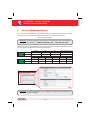
Aurora® Power Service
USA
Aurora Power Service
France
00 800 00 28 76 72
Aurora® Power Service
Germany
0800-2200211
Aurora® Power Service
Italy
00 800 00 28 76 72
Aurora® Power Service
Spain
00 800 00 28 76 72
Aurora Power Service
Middle East
00 800 00 28 76 72
Aurora® Power Service
Australia
+61 2 9735 3111
Aurora® Power Service
China
+86 755 2988 5888
Aurora® Power Service
Singapore
+65 6896 3363
Aurora® Power Service
Malaysia
+603-8025 9963
®
®
877-261-1374
QUICK INSTALLATION GUIDE
Model: PVI-AEC-EVO
PVI-AEC-EVO-LIGHT
Rev. 3.1 - Aurora® is a trademark by Power-One - Product is subject to technical improvements
BCB.00029.5 REV. AB
PVI-AEC-EVO
PVI-AEC-EVO LIGHT
Monitoring System
- USER MANUAL -
QUICK INSTALLATION GUIDE
SAVE THESE DOCUMENT IN A SAFE PLACE!
IMPORTANT SAFETY INSTRUCTION!
This manual contains important safety instruction that must be followed during the
installation and start-up of the device. It s recommended to give special attention to the
installation instruction in order to reduce the risks pf electric shock and prevent damage
to the device.
Note: This document contains proprietary information of Power-One, Inc.
The contents of this document or any part thereof should not be reproduced or disclosed
to any third party whitout Power-One s express written consent.
Note: Any changes / modification not approved by the responsible party could void the
user authority to operate the equipment.
BCB.00029.5 REV. AB
REV. 3.1
11-10-2013
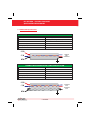
PVI-AEC-EVO / PVI-AEC-EVO LIGHT
QUICK INSTALLATION GUIDE
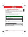
CONTENTS
A.
Product Description
2
B.
Package Content
3
C.
User Interface and Use of the Display
4
D.
Pin-Outs of System Connectors
5
E.
Power Supply Connections and System Start Up
6
F.
Date and Time Settings
7
G.
Connection of the RS485 Line and Inverter Acquisition Check
7
H.
Configuration of the Analog Inputs
11
I.
System Configuration for Connection to the LAN Network (Ethernet Port)
14
L.
Internal Webserver access
17
M.
Mac Address Identification
20
N.
Firmware Updating
21
Appendices
1)
2)
3)
4)
Sensor Connection Diagrams
RS485 Cable Features
Display flow-charts
Compliance Requirements
1 - EN
EN - ENGLISH
Monitoring System
A.
Product Description
The PVI-AEC-EVO is a monitoring and checking system for photovoltaic systems made with Power-One Aurora
products. In the following pages we will make reference to the system meaning both versions of the product.Whereas
the characteristics of product are different the model will be specified .
The product allows to acquire parameters from the inverter and string-comb (in accordance with the design of the
central inverter monitoring system) through the RS485 line with the Power-One proprietary protocol.
The system is equipped with two equivalent RS485 ports and each of them allows a maximum of 62 string inverters
or 62 55kW conversion modules (centralized modular inverters) to be acquired; It is also possible to use the
communication port RS485/1 (Ref.Par.D) to acquire parameters from ISKR AMECO MT831 power meters equipped
with Modbus communication interface.
Note: For PVI-AEC-EVO LIGHT, the max number of string inverter manageable by the system is 5, which can
be connected only by RS485/2 (Ref.Par.D).Only the followings (in all of their variants) are allowed:
PVI-2000(-OUTD)
UNO-2.0/2.5-I-OUTD
PVI-3600
PVI-3.0/3.6/4.2-TL-OUTD*
PVI-3.8/4.6-I-OUTD
PVI-5000/6000-TL-OUTD*
PVI-10.0/12.5-TL-OUTD*
PVI-10.0/12.0-I-OUTD
(*): Compatibilityisalsoextendedtopreviousnationalversions(Ex:PVI-3.6-OUTD-UK)
In the PVI-AEC-EVO LIGHT the communication port RS485/1 (Ref. Par. D) can be used only to acquire
parametersfrom ISKRAMECOMT831 powermetersequippedwithModbuscommunicationinterface.
The system is equipped with three analog inputs for the connection of sensors for the measurement of environmental
parameters: Power-One offers in its catalogue a complete range of radiation sensor,cell and ambient temperature,speed
and wind direction .
The system also has six digital inputs for acquiring state signals (for example auxiliary contacts of power switches) which
are associated with state alarm conditions.
With respect to the user interface, the system is equipped with a 2x16 character display and four keys as well as an
integrated webserver with html pages which are accessible through LAN connection.
The initial system configuration (check that the inverter parameters are acquired, analog inputs configuration, LAN
network parameters configuration) can be carried out completely through the display and keys; for displaying the
detailed parameters of the inverters and/or of the string-combs,as well as for the advanced configurations it is necessary
to access the pages of the integrated web server.
The PVI-AEC-EVO works in conjunction with the service web portal AuroraVision:by registering for this service you will be
able to carry out monitoring and remote management of systems associated with your account.
The web portal AuroraVision is available on the website:
www.Auroravision.net
2 - EN
PVI-AEC-EVO / PVI-AEC-EVO LIGHT
QUICK INSTALLATION GUIDE
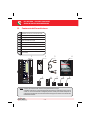
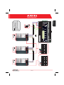
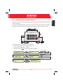
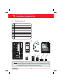
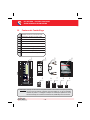
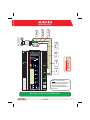
B.
Package content
1
AURORA PVI-AEC-EVO / PVI-AEC-EVO LIGHT
2
Power Supply 100-240Vac 50-60Hz / 24Vdc
3
Power Supply connection cable
4
Quick Installation Guide
5
SD Card (assembled)
6
I/O Terminal Blocks Counterparts (assembled)
7
RS485 Terminal Blocks Counterparts (assembled)
8
Relais Terminal Blocks Counterparts (assembled)
9
Power supply Terminal Blocks Counterparts
(assembled)
1
2
3
4
-
-
+
+
Output DC
24V 0.75A
STEP POWER
DC
OK
Input AC
100-240V
L(+)
N(-)
5
6
7
8
9
Note: Check the package content corresponds to the above list.
Please check the box and each single item inside has no defect.In case claims to the shipping company
and communicates quickly to the assistant technical service or to the Customer service of Power-One.
3 - EN
C.
User interface and use of the display
The system features a 2x16 character display,four buttons for navigating menus,and three LEDs to indicate device status.
Using the display and the buttons on the front panel it is possible to perform the initial configuration of the system (check
of parameter acquisition from inverter,analog input configuration,and configuration of LAN network parameters).
For displaying the detailed parameters of the inverters and/or of the string-combs, as well as for the advanced
configurations it is necessary to access the internal web server following the procedure described in paragraph L .
A list of functions accessible from the display is shown in the table in Appendix 3.
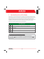
USE OF BUTTONS
'Enter' button. Used to confirm an action,to access the main menu or the sub-menu corresponding to
the selected entry (indicated by the > symbol),or to go to the next digit to change.
'Down' button. Used to scroll down through the menu items, or to scroll the numerical scale in
descending order.
'Up' button. Used to scroll up through the menu items, or to scroll the numerical scale in ascending
order.
'Esc' button. Used to return to the previous menu or to return to the previous digit to change.
Access to the main menu with administrator privileges
To perform the initial configuration it is necessary to access the various display menus as administrator.
Press the 'ENTER' key (
) and insert password 0010: To insert the password press the arrow keys (
) to
change the value and the 'ENTER' key to confirm the value. This password gives access to all the display setting submenus of the system.
4 - EN
EN - ENGLISH
Monitoring System
PVI-AEC-EVO / PVI-AEC-EVO LIGHT
QUICK INSTALLATION GUIDE
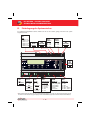
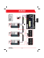
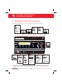
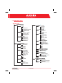
D.
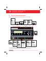
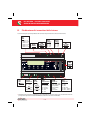
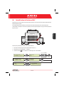
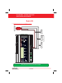
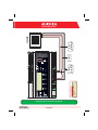
Pin-Out of System Connectors
The diagram below shows the pin-out of the connectors which allow the system connection.
J5
RELAY
1) RELAY 1 - C
2) RELAY 1 - N.O
3) RELAY 2 - C
4) RELAY 2 - N.O
5) RELAY 3 - C
6) RELAY 3 - N.O
J17
S2
J12
120Ω TERM.
RS485/1
GROUND
1
2
3
4
5
RS485/1*
1) RTN
2) - T/R
3) +T/R
4) +5V
6
J15
RS485/2
1) RTN
2) - T/R
3) +T/R
4) +5V
4 3 2 1
S1
120Ω TERM.
RS485/2
4 3 2 1
J9
EXPANSION
BUS
1
J7
LAN
IEEE802.3u
2
2
J18
BATTERY IN
1) + Batt.
2) - Batt.
NOTE:
Only for dedicated
accessory
PVI-BATTERY-PACK
1
J8
Vin DC
1) + Vcc
2) - Vcc
INPUT DC:
24 Vdc (max. 48 Vdc)
0,3 A
NOTE:
Use the provided
power supply
1 2 3 4 5 6
J3
ANALOG INPUT
PT100/1000
1) PT_ALIM
2) PT_SENSE
3) PT_RTN
4) AIn_RTN
5) AIn 1
6) AIn 2
1 2 3 4 5 6
1 2 3 4 5 6
J20
DIGITAL I/O
1) DO_RTN_PWM1
2) DO_RTN_PWM2
3) DO_PWM 1
4) DO_PWM 2
5) DIn 1
6) DIn_RTN
J4
DIGITAL I/O
1) DIn 2
2) DIn 3
3) DIn 4
4) DIn_RTN
5) DIn 5 / CONT 2
6) DIn 6 / CONT 1
* In the PVI-AEC-EVO LIGHT model the RS458/1 port (J17) is not available as inverter communication port, but can be used only to
acquire parameters from ISKRAEMECO power meters equipped with Modbus communication interface.
5 - EN
EN - ENGLISH
Monitoring System
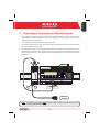
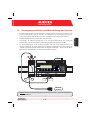
E.
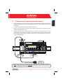
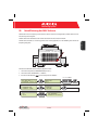
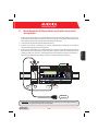
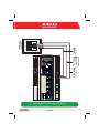
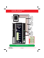
Power Supply Connections and System Start Up
1. Connect the power supply to the power supply network (100/240V 50/60Hz): the "Power" led on the power
supply will light up steadily.Check that the output voltage of the power supply is 24Vdc.Disconnect the power
supply from the power supply network.
2. Connect the functional earth to the PVI-AEC-EVO using terminal J12.
3. Connect the output of the power supply to the power supply terminal block of the PVI-AEC-EVO respecting the
polarity and using the wiring provided.
4. Connect the power supply to the power supply network: After a first starting phase (lasting about 30 seconds)
during which the system is not able to receive any input from the user,the green "Power ON" led will remain lit.
The message PVI-AEC-EVO...." (in the first of the two lines) and date/time (in the second of the two lines) will
be displayed.
-
-
+
+
Output DC
24V 0.75A
STEP POWER
DC
OK
Input AC
100-240V
L(+)
L(+)
2
1
N(-)
N(-)
-Vcc
+Vcc
50-60 Hz
100-240 V~
Note: The system must be supplied ONLY with power supply and wiring provided; otherwise the CE
conformity will not be longer valid.
6 - EN
PVI-AEC-EVO / PVI-AEC-EVO LIGHT
QUICK INSTALLATION GUIDE
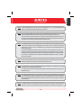
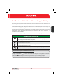
F.
Date and time settings
1. Enter the main menu as administrator (See par.'C ).
2. Access the menu 'SETTINGS' > 'DATALOGGER' and then select the 'SET DATE' sub-menu. This enables to set the
correct date in the system.
3. Return to the menu 'DATALOGGER' and then select the 'SET TIME' sub-menu. This enables to set the correct time
in the system.
SET PIN TO 0010
G.
PVI-AEC-EVO ......
12.00.00 01/01/11
ENTER
menu pin
0***
>settings
change password
ENTER
>set date
set time
ENTER
>set date
01/01/11
>set time
network
ENTER
>set time
12.00.00
>datalogger
io settings
NEXT
DIGIT
ENTER
CHANGE VALUE
NEXT
FIELD
ENTER
CHANGE VALUE
NEXT
FIELD
ENTER
CHANGE VALUE
ENTER
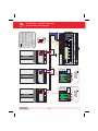
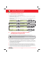
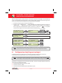
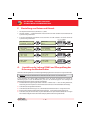
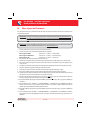
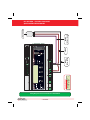
Connection of the RS485 line and inverter acquisition
check
The connection of the RS485 line must be carried out respecting the pin-outs of the J15 and/or J17 connectors.
Note: For PVI-AEC-EVO LIGHT, the only usable RS485 port for inverter monitoring is the RS485/2,
correspondent to connector J15.
I
t is recommended to connect the RS485 line when all the equipment is switched off (both the monitoring system
and the inverters) and to start up the monitoring system first and then the inverters. It is recommended to:
l Use a cable for RS485 applications with the following characteristics: 1 twisted pair + 1 conductor or two
twisted pairs, Screen and characteristic Impedance equal to 120Ω . For further information on the cable to be
used refer to Appendix 2.
l Make sure the signals correspond.
l Make sure that all three lines (+T/R,-T/R and RTN) are connected according to the diagrams in pages 9 - 10.
l Make sure that the communication line screen is grounded according to the diagrams in pages 9 - 10).
l Make sure that each element in the chain (each inverter or each 55kW module) has a RS485 address that is
different from the others.This address can be set via the display of the inverter.
7 - EN
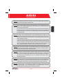
Note: For PVI-AEC-EVO LIGHT, the inverters must be set with addresses: 1, 2, 3, 4, 5. The configuration of
address 1 corresponds to "AUTO" settings as inverter address.
Note: When connecting multiple units (string inverter or/and 55kW conversion modules) it is necessary
to wire the RS485 communication line according to the daisy-chain diagram (enter-exit).
The last inverter of the daisy-chain must be 'terminated' by activating the termination resistance of
the 120Ω communication line through switching the dip-switch located on the motherboard in the
string inverters,and inside each framework of the central inverters.
Note: The maximum number of units (string inverters or/and 55kW conversion modules) that can be
connected to a RS485 port of the PVI-AEC-EVO is 62. In order to connect a number of units greater
than 62 it is necessary to use the second RS485/2 port respecting the same wiring diagram used for
the main RS485/1 port.
In the PVI-AEC-EVO LIGHT the number of inverters that can be acquired is limited to a maximum of 5
strings inverters which can be connected by RS485/2 (Ref. Par. D). Compatible models (in every their
variation) for the PVI-ACE-EVO LIGHT version are: PVI-2000(-OUTD); UNO-2.0/2.5-I-OUTD; PVI-3600;
PVI-3.0/3.6/4.2-TL-OUTD; PVI-3.8/4.6-I-OUTD; PVI-5000/6000-TL-OUTD; PVI-10.0/12.5-TL-OUTD;
PVI-10.0/12.0-I-OUTD.
Note: In case of mixed systems, the presence of both string inverters and central inverters on the same
RS485 line is permitted.To wire this line follow all the directions above.
Note: All string inverters (except for models PVI-5000/6000-TL-OUTD) have a clamp that allows giving
continuity to the cable shield of the RS485 line.
For single-phase inverters this clamp is indicated by the words LNK, for three-phase inverters it is
indicated by SCLD .
Note: The centralized inverters have a clamp, which is located in the signal terminal block and marked
with X23 , that allows to link to ground the shield of each singular portion of the communication
line independently from the other portion of communication line. (must not be given continuity to
the cable shield).
Note: For further details on the wiring of the RS485 line and/or the activation of the termination
resistances,refer to the user manual of string inverters and to the user manual of central inverters.
8 - EN
EN - ENGLISH
Monitoring System
AURORA
9 - EN
+T/R
RTN
RS485
+T/R
-T/R
ON
OFF
120Ω
Term.
Resistor
ON
OFF
120Ω TERM.
RESISTOR ON
120Ω TERM.
RESISTOR
RTN
RTN +T/R -T/R
RS485
-T/R
AURORA
-T/R
+T/R
RTN
-T/R
ON
OFF
ON
OFF
120Ω
Term.
Resistor
120Ω TERM.
RESISTOR
RTN
120Ω TERM.
RESISTOR OFF
RTN +T/R -T/R
RS485
+T/R
RS485
+T/R
RS485
ON
OFF
120Ω
Term.
Resistor
4 3 2 1
120Ω TERM.
RESISTOR ON
4 3 2 1
RTN
+T/R
-T/R
Note: Make sure that each
inverter in the chain has a RS485
address that is different from the
others. For PVI-AEC-EVO LIGHT,
the inverters must be set with
addresses: 1, 2, 3, 4, 5. The
configuration of address 1
corresponds to "AUTO" settings as
inverteraddress.
PVI-AEC-EVO / PVI-AEC-EVO LIGHT
QUICK INSTALLATION GUIDE
RTN
-T/R
AURORA
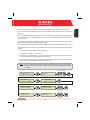
10 - EN
A
A
X20 X21 X22 X23 X24 X25 X26 X27
D
D
X20 X21 X22 X23 X24 X25 X26 X27
X20 X21 X22 X23 X24 X25 X26 X27
RTN +T/R -T/R
A
RTN +T/R -T/R
D
A
120Ω TERM.
RESISTOR OFF
D
X20 X21 X22 X23 X24 X25 X26 X27
120Ω TERM.
RESISTOR ON
A
D
X20 X21 X22 X23 X24 X25 X26 X27
120Ω TERM.
RESISTOR OFF
4 3 2 1
120Ω TERM.
RESISTOR ON
4 3 2 1
RTN
+T/R
-T/R
Note: Make sure that each
55 kW module in the chain
has a RS485 address that is
different from the others.
EN - ENGLISH
Monitoring System
PVI-AEC-EVO / PVI-AEC-EVO LIGHT
QUICK INSTALLATION GUIDE
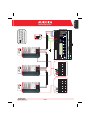
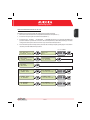
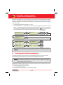
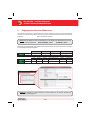
After carrying out these checks, start up first the monitoring system and then the inverters. The system automatically
carries out a scan of the RS485 bus and automatically detects the available inverters.The presence of the inverters can be
checked directly from the display.
1. Enter the main menu as administrator (See par.'C ).
2. Access the 'CURRENTVALUES' > 'ENERGY INVERTERS' menu (to display the string inverters) and/or 'CURRENTVALUES' >
'ENERGY RACK' (to display the 55kW conversion modules). The number of inverters detected during the scan will be
displayed;the list of the monitored inverters identified by the Serial Number (S/N) can be displayed by scrolling using
the arrow keys (
).
SET PIN TO 0010
PVI-AEC-EVO ......
12.00.00 01/01/11
ENTER
>CURRENT VALUE
SETTINGS
ENTER
>ENERGY INVERTERS
ENERGY RACK
ENTER
>ENERGY RACK
ENERGY PLANT
ENTER
menu pin
0***
CHANGE VALUE
30 INVERTERS
>INVERTER SN 123456
RACK
>RACK
N. 1
SN 123456
NEXT
DIGIT
ENTER
CHANGE
INVERTER
CHANGE
RACK
Note: The time necessary for the PVI-AEC-EVO to scan and acquire the inverters depends on the number of
inverterspresentonthesameline(sometimesseveralminutes).
H.
Configuration of the Analog Inputs
The connection of the analogue sensors must be carried out respecting the pin-outs of the J3 connector.
The system has two 0-10Vdc inputs and a PT100/1000 input.
Note: To each analogue input (both 0-10Vdc and PT100/1000 types) it is possible to connect only one analog
sensor. Itisthereforenotpossibletoconnectmultiplesensorsonthesameanaloginput.
With respect to the connection of the PT100/1000 sensors,the system is able to carry out the sensor reading through the
connection of three-wires:
l A sensor power supply line (PT_ALIM);
l A reading line (PT_SENSE);
l A power supply and reading closing line (PT_RTN).
11 - EN
EN - ENGLISH
Monitoring System
The measurement is carried out between PT_SENSE and PT_RTN, therefore the element to be measured must be wired
between these two signals.
The PT100/PT1000 sensor is automatically recognised by the system and is therefore acquired without the need for
further settings.
Regarding the connection of the sensors with output range 0...10Vdc,these must be powered and the power supply can
be taken directly from the system power supply; the grounding of the power supply and the grounding of the signal
reading is the same.
For the sensor connection, beside the power supply, it is necessary to connect the signal proportionally to the quantity
measured at one of the two analog inputs available (Aln1/Aln2).
The grounding of the signal to be measured (if different from the grounding of the power supply within the Power-One
sensor range only in the wind speed sensor PVI-AEC-WIND-COMPACT) must be connected to the Aln_RTN clamp.
After carrying out the connections it is necessary to configure the sensor in the system so that the correct quantity is
acquired:
1. Enter the main menu as administrator (See par.'C ).
2. Access the menu 'SETTINGS'>'IOSETTINGS'.
3. Select the “ANALOG INPUT1” item and then select the sensor model connected to the AIn1 input of the system (the
selected model will be identified with an asterisk (*) ).
4. Select the “ANALOG INPUT2” item and then select the sensor model connected to the AIn2 input of the system (the
selected model will be identified with an asterisk (*) ).
Note: In case of connecting PT100/1000 sensors with only two terminals,connect a terminal to the PT_SENSE
clampandaterminaltothePT_RTNclamp,thenmakeajumperbetweenPT_ALIMandPT_SENSE.
SET PIN TO 0010
PVI-AEC-EVO ......
12.00.00 01/01/11
ENTER
menu pin
0***
>settings
change password
ENTER
>io settings
UPGRADE FIRMWARE
>ANALOG INPUT1
ANALOG INPUT2
ENTER
>ANALOG INPUT1
T1000-INTEGR
*
>ANALOG INPUT2
PULSE IN1
ENTER
>ANALOG INPUT2
RAD-13TC
*
12 - EN
CHANGE VALUE
NEXT
DIGIT
ENTER
CHANGE
SENSORS
ENTER
CHANGE
SENSORS
ENTER
ENTER
PVI-AEC-EVO / PVI-AEC-EVO LIGHT
QUICK INSTALLATION GUIDE
To read the measurements of the sensors and to check their accuracy follow the instructions below:
1. Enter the main menu as administrator (See par.'C ).
2. Access the menu 'CURRENT VALUES' > 'ANALOG VALUE'. The quantity value will be displayed for each of the
analog inputs.
SET PIN TO 0010
PVI-AEC-EVO ......
12.00.00 01/01/11
ENTER
menu pin
0***
>CURRENT VALUE
SETTINGS
ENTER
>ANALOG VALUE
DIGITAL VALUE
>T1000-INTEGR
20.0 DEGC
CHANGE VALUE
NEXT
DIGIT
ENTER
ENTER
AN1
CHANGE
INPUT
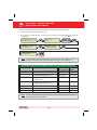
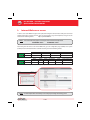
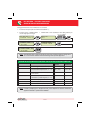
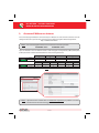
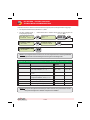
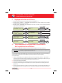
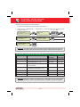
Note: In the following table it is reported a list of the sensor which are present in the catalogue Power-one .
Fortheconnectionofthesesensors,pleasemakereferencetodiagrams shown in Appendix 1.
SENSORS WITH ANALOG OUTPUTS COMPATIBLE WITH PVI-AEC-EVO (POWER-ONE CATALOGUE)
MODELL
TYPE
DISPLAY
IDENTIFICATIONCODE
OPERATIVE
RANGE
PVI-AEC-IRR
Radiation sensor (W/m2 --> V)
IRR
0-1200 W/m
PVI-AEC-IRR-T
Radiation sensor with integrated cell
2
temperature sensor (W/m / °C --> V)
IRR-T_Irr /
IRR-T_Temp
0-1200 W/m
-20 to +80 °C
PVI-AEC-T100-ADH
Adhesive module temperature sensor
(back cell) PT100
T100-ADH
-50 to +150 °C
PVI-AEC-T1000-INTEGR
Ambient temperature sensor connected to
PT100/0...10Vdc converter (°C --> V)
T1000-INTEGR
-50 to +50 °C
2
2
PVI-AEC-T1000-BOX
Ambient temperature sensor PT100
T1000-BOX
-50 to +50 °C
PVI-AEC-PYR-1300
Pyranometer ( W/m --> V)
Pirano_0-20mA
0-1300 W/m
PVI-AEC-WIND-COMPACT
Wind speed sensor (m/s --> V)
WIND-COMPACT
0 - 50 m/s
2
2
Note: The system is predisposed for the connection to other sensors available: ZippZonen Pyranometer 01600W/m2 and Pyranometer0-2000W/m2.
13 - EN
EN - ENGLISH
Monitoring System
I.
System Configuration for connection to the LAN
Network (Ethernet Port)
The connection to the PC of PVI-AEC-EVO can be made through direct connection via Ethernet cable, or connecting
both devices to a local network LAN (via router,hub or switch).
In case of direct connection,it is enough to connect the two devices between them through a Ethernet cable and set
the network parameters of PVI-AEC-EVO and of the PC to make sure they are compatible between them.
Note: The IP address of the PC and the IP address of the PVI-AEC-EVO must belong to the same group but
they must not be identical,for instance:
PC IP ADDRESS: 20.200.200.1
PVI-AEC-EVO IP ADDRESS: 20.200.200.24
The subnet mask must be the same for both devices, for instance: 255.0.0.0
In case of connection to a pre-existing local network LAN,it is necessary to assign to PVI-AEC-EVO the network parameters
which have to be compatible with the local network to which the PVI-AEC-EVO is connected. Make reference to the
network administrator to obtain the correct parameters of the network.
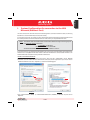
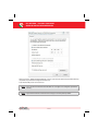
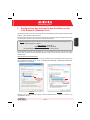
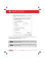
CHANGE OF PC NETWORK PARAMETERS
In order to change pc network parameters, please select Start and then Control Panel , click on Network
Connections : the new window will show the network connections; with the right button of your mouse click on
Local Area Connection and select Properties ;as shown in the following figure.
Windows XP
Windows 7/8
Select Internet Protocol (TCP/IP) (or Internet Protocol Version 4 (TCP/IPv4) in Windows 7/8) and click on
Properties .
14 - EN
PVI-AEC-EVO / PVI-AEC-EVO LIGHT
QUICK INSTALLATION GUIDE
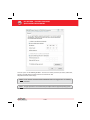
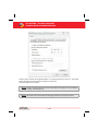
Select the option Use the following IP address and insert the network parameters (IP address, Subnet Mask,
Gateway) compatible with the network parameters set in the PVI-AEC-EVO.
DNS parameters fields can be let empty.
Note: In case of direct connection between PVI-AEC-EVO and PC we suggest not to set Gateway
parameters.
Note: This type of procedure is to be considered only an example for the most popular operating systems.
15 - EN
EN - ENGLISH
Monitoring System
CHANGETHE PVI-AEC-EVO NETWORK PARAMETERS
:in order to change the PVI-AEC-EVO network parameters,please follow the procedure below:
1. Power on the system and wait for the start up phase to complete (Ref.Par.'E ).
2. Enter the main menu as administrator (Ref.Par.'C ).
3. Access the menu “SETTINGS” > “DATALOGGER” > “NETWORK”. The parameters for connection to the LAN
network (IP address, Subnet mask, Gateway) may be modified using the items of the "NETWORK" menu. This
allows to configure the system for connection to the LAN network and/or for direct connection to a PC.
4. At the end of the setting operations, return to the main screen, then switch off and switch on the system to
make the settings take effect.
SET PIN TO 0010
PVI-AEC-EVO ......
12.00.00 01/01/11
ENTER
menu pin
0***
>settings
change password
ENTER
>datalogger
io settings
>NETWORK
SET DATA
ENTER
>IP SETTING
SUBNET MASK
ENTER
>IP SETTING
XXX.XXX.XXX.XXX
>SUBNET MASK
ip gateway
ENTER
>subnet mask
XXX.XXX.XXX.XXX
>IP gateway
ip method
ENTER
>IP gateway
XXX.XXX.XXX.XXX
16 - EN
NEXT
DIGIT
ENTER
CHANGE VALUE
NEXT
DIGIT
ENTER
CHANGE VALUE
NEXT
DIGIT
ENTER
CHANGE VALUE
NEXT
DIGIT
ENTER
CHANGE VALUE
ENTER
PVI-AEC-EVO / PVI-AEC-EVO LIGHT
QUICK INSTALLATION GUIDE
L.
Internal Webserver access
In order to access to the Webserver pages of the system, after having done the connection of the system to the local
network LAN or direct connection to the PC, open an internet browser (e.g. Internet Explorer) and type into the
address bar the following address:
http://<system IP address>
Note: To access the webserver pages it is necessary to insert a username and a password:
USERNAME: admin
PASSWORD: admin
After having done the access to the internal Webserver, go to the configuration page (CONFIG) of the system
(PLANT) and insert the installation GPS coordinates according to one of the following formats:
Indicator
Degrees
Point
Latitude
N43.33
N
43
.
Degrees (Hundredths of degree)
33
Longitude
E11.35
E
11
.
35
Degrees
Indicator
Minutes
Quotation Mark
Seconds
Double quotation mark*
Latitude
43N50’20”
43
N
50
‘
20
“
Longitude
11E23’30”
11
E
23
‘
30
“
* The Double Quotation Mark ( ” ) symbol must be inserted by entering twice the quotation mark ( ' ) symbol.
Note: To set the GPS parameter is mandatory to assure the proper working of monitoring system.
17 - EN
In order to allow the PVI-AEC-EVO to communicate with the Aurora Vision web portal,access the configuration page
(CONFIG) of the network (NETWORK) and check that in section 'DATA TRANSFER', under item 'IP Address Portal'
there is the IP address 63.236.63.180.
Note: If the setting 'IP Portal Address' does not correspond to 63.236.63.180, change it by entering the
above-mentioned address and press 'Confirm' to activate it. After this operation, reset the system
(ON-OFF).
Note: To make the system fully functioning it is essential that the same system is constantly connected
to the internet so that it is able to communicate with the Power-One server. This is essential to
graphically shows the data on web pages as well as for sending alarm and/or report messages.It is
essential that the LAN network in which the PVI-AEC-EVO is wired is such that it allows the
connection to the IP address 63.236.63.180 to be reached through port 80, so that the
PVI-AEC-EVO is able to communicate with the portal management server.
18 - EN
EN - ENGLISH
Monitoring System
PVI-AEC-EVO / PVI-AEC-EVO LIGHT
QUICK INSTALLATION GUIDE
19 - EN
EN - ENGLISH
Monitoring System
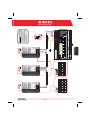
M.
MAC Address Identification
During the process of association of PVI-AEC-EVO in Aurora Vision you will be prompted to enter the MAC address of the
PVI-AEC-EVO present in the system.
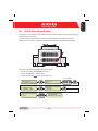
It is possible to obtain the MAC Address of your PVI-AEC-EVO observing the label on the right side of the product.
The MAC Address is composed of 12 characters (separated by a colon) shown in red for example in the figure below.
PVI-AEC-EVO
P-1 P/N: 3I72001F100G
Prod. Week 16/11
S/N: 3I72001F100G 000464VI1611
MAC ADDRESS: 00:50:C2:42:38:24
Alternatively it's possible to obtain the MAC Address from the display:
1. Enter the main menu as ADMINISTRATOR (refer to par. C )
2. Enter the “INFORMATION” > “PRODUCT” menu.
3. Using the arrow buttons (
) move to “MACADDRESS” view.
SET PIN TO 0010
PVI-AEC-EVO ......
12.00.00 01/01/11
ENTER
menu pin
0***
>INFORMATION
CURRENT VALUE
ENTER
>PRODUCT
NETWORK
pN
3I72
CHANGE
MENU
MAC ADDRESS
00:50:C2:42:38:24
20 - EN
CHANGE VALUE
ENTER
NEXT
DIGIT
ENTER
PVI-AEC-EVO / PVI-AEC-EVO LIGHT
QUICK INSTALLATION GUIDE
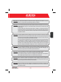
O. Firmware updating procedure via SD Card
It is possible to upgrade the firmware of the PVI-AEC-EVO either locally using the SD Card, or remotely using the web
portal AuroraVision.
Note: The firmware update via SD card should be carried out only if it is not possible to update the firmware
viatheAuroraVisionwebportal.
Note: For details on the procedure for the firmware updating through the web portal Aurora Vision, refer
to the documentation on the website www.Auroravision.net.
1. Access the display by entering the user password 0000.
2. Check and note the current firmware versions installed:
Firmware AVR:
Firmware Display:
Firmware IO:
Information > Product > Firmware AVR
Information > Product > Firmware Display
Information > Product > Firmware IO
3. Turn off the PVI-AEC-EVO and wait at least one minute.
4. Disconnect all available connections from the PVI-AEC-EVO (RS458 line(s),LAN connection,sensors).
5. Remove the SD Card from the slot on the PVI-AEC-EVO front panel by pressing the SD Card gently.
6. Insert the SD Card into the SD Card reader or into to the SD Card reader slot of the PC.
7. Delete the folders upgrade,web,lang and config from the SD Card.
8. Copy the new folders upgrade,web,lang and config into the root of the SD Card.
9. Remove the SD Card from the SD Card reader or from the SD Card reader slot.
10. Insert the SD Card into the slot on the PVI-AEC-EVO front panel by pressing the SD Card gently to lock it into place.
11. Turn on the PVI-AEC-EVO and wait about one minute.(N.B.: Power failure during update may cause serious damage
to the device).
12. Enter the display by pushing the ENTER button and insert the password 0010 ; push ENTER to confirm.
13. Follow the path: “SETTINGS > UPGRADE FIRMWARE > UPGRADE AVR” press ENTER to confirm;wait the completing of
upgrade (few minutes).After the upgrade the system will reboot:wait the complete reboot (date/time will be shown
on the display).
14. Enter the display by pushing the ENTER button and insert the password 0010 ; push ENTER to confirm.
15. Follow the path “SETTINGS > UPGRADE FIRMWARE > UPGRADE ADC” press ENTER to confirm;wait the completing of
upgrade (few minutes). The upgrading process will be completed when the message “Upgrade Success” will be
displayed.
21 - EN
16. Follow the path “SETTINGS>UPGRADEFIRMWARE>UPGRADEDISPLAY” press ENTER to confirm;wait the completing
of upgrade (few minutes).The upgrading process will be completed when the message “Upgrade Success” will be
displayed.
17. Follow the path “SETTINGS > UPGRADE CONFIG” press ENTER to confirm; wait the completing of upgrade (few
minutes).The upgrading process will be completed when the message “UPGRADE CONFIG” will be displayed again.
Press ESC to exit.
18. Switch off the system,restore all connections (RS485 line(s),LAN connection,sensors),then switch on the system.
22 - EN
EN - ENGLISH
Monitoring System
PVI-AEC-EVO / PVI-AEC-EVO LIGHT
GUIDA DI INSTALLAZIONE RAPIDA
INDICE
A.
Descrizione del prodotto
2
B.
Contenuto della confezione
3
C.
Interfaccia Utente ed utilizzo del display
4
D.
Piedinatura dei connettori del sistema
5
E.
Collegamento dell alimentazione del sistema
6
F.
Impostazione di data ed ora
7
G.
Collegamento della linea RS485 e verifica dell acquisizione degli inverter
7
H.
Configurazione degli ingressi analogici
11
I.
ConfigurazionedelsistemaperlaconnessioneinreteLAN(portaEthernet)
14
L.
Accesso al Webserver interno
17
M.
Identificazione del MAC Address
20
N.
Aggiornamento Firmware
21
Appendici
1)
2)
3)
4)
Schemi di collegamento sensori
Caratteristiche cavo RS485
Display flow-charts
Requisiti di conformità
1 - IT
Monitoring System
Descrizione del Prodotto
I sistemi PVI-AEC-EVO e PVI-AEC-EVO LIGHT sono sistemi di monitoraggio e controllo degli impianti fotovoltaici realizzati
con prodotti Power-One. Nel seguito si farà riferimento al "sistema" intendendo entrambe le versioni di prodotto,mentre
verrà specificato il modello nel caso in cui le loro caratteristiche siano differenti.
Il prodotto consente l'acquisizione dei parametri da inverter e stringcomb (secondo l'architettura di monitoraggio
degli inverter centralizzati) attraverso linea RS485 con protocollo proprietario Power-One.
Il sistema dispone di due porte RS485 (equivalenti tra loro) che permettono l'acquisizione, ciascuna, di 62 inverter
di stringa o di 62 moduli di conversione da 55kW (inverter centralizzati modulari); E inoltre possibie utilizzare la
porta di comunicazione RS485/1 (rif. capitolo D) per l acquisizione di parametri da contatori ISKRAMECO MT831
dotati di interfaccia comunicazione Modbus.
Nota: Nella versione PVI-AEC-EVO LIGHT il numero di inverter monitorabili è limitato ad un massimo di 5
inverter di stringa,collegabili unicamente alla porta RS485/2 (Rif.Par.D). I modelli compatibili (in tutte
lelorovarianti)sonoiseguenti:
PVI-2000(-OUTD)
UNO-2.0/2.5-I-OUTD
PVI-3600
PVI-3.0/3.6/4.2-TL-OUTD*
PVI-3.8/4.6-I-OUTD
PVI-5000/6000-TL-OUTD*
PVI-10.0/12.5-TL-OUTD*
PVI-10.0/12.0-I-OUTD
(* ): Lacompatibilitàèestesaanchealleprecedentiversioninazionali(Es: PVI-3.6-OUTD-IT)
Nella versione PVI-AEC-EVO LIGHT la porta di comunicazione RS485/1 (Rif.Par.D) può essere utilizzata
unicamente per l acquisizione di parametri da contatori ISKRAMECO MT831 dotati di interfaccia
comunicazioneModbus.
Il sistema dispone di tre ingressi analogici per il collegamento di sensori per la misura dei parametri ambientali: PowerOne offre, a catalogo, una gamma completa di sensori di irraggiamento, temperatura ambiente e di cella, velocità e
direzione del vento.
Il sistema mette a disposizione anche sei ingressi digitali per l'acquisizione di segnali di stato (ad esempio contatti ausiliari
di interruttori di potenza) a cui sono associate condizioni di allarme di stato.
Relativamente all'interfaccia utente, il sistema dispone di un display 2x16 caratteri e quattro pulsanti oltre che di un
webserver integrato di pagine html accessibile attraverso connessione LAN.
La configurazione iniziale del sistema (verifica dell'acquisizione dei parametri da inverter, configurazione degli ingressi
analogici,configurazione dei parametri di rete LAN) può essere eseguita interamente attraverso il display ed i pulsanti;per
la visualizzazione dei parametri di dettaglio degli inverter e/o delle stringcomb nonchè per le configurazioni avanzate è
necessario accedere alle pagine di webserver integrato.
Il PVI-AEC-EVO lavora in abbinamento al servizio di portale web Aurora Vision:effettuando la registrazione a tale servizio
sarà possibile effettuare il monitoraggio e la gestione da remoto degli impianti associati al proprio account.
Il portale web AuroraVision è disponibile alla pagina web: www.Auroravision.net
2 - IT
IT - ITALIANO
A.
PVI-AEC-EVO / PVI-AEC-EVO LIGHT
GUIDA DI INSTALLAZIONE RAPIDA
B.
Contenuto della confezione
1
AURORA PVI-AEC-EVO / PVI-AEC-EVO LIGHT
2
Alimentatore 100-240Vac 50-60Hz / 24Vdc
3
Cablaggio connessione alimentatore
4
Guida di installazione rapida
5
SD Card (assemblata)
6
Controparti morsettiere I/O (assemblate)
7
Controparti morsettiere Rs485 (assemblate)
8
Controparte morsettiera Relè (assemblata)
9
Controparte morsettiera Alimentazione
(assemblata)
1
2
3
4
-
-
+
+
Output DC
24V 0.75A
STEP POWER
DC
OK
Input AC
100-240V
L(+)
N(-)
5
6
7
8
9
Nota: Verificarecheilcontenutodella confezionecorrispondaallalistadicuisopra.
Controllare inoltre che non vi siano danneggiamenti alla confezione, al dispositivo e agli accessori in
corredo. In caso di non conformità si consiglia di presentare reclamo presso la ditta di trasporti e di
comunicare tempestivamente al servizio di assistenza tecnica oppure al customer service di Power-One
ladifformitàriscontrata.
3 - IT
C.
Interfaccia Utente ed utilizzo del display
Il sistema dispone di un display 2x16 caratteri, quattro pulsanti per la navigazione nei menu e tre LED che indicano
lo stato del dispositivo.
Attraverso l uso del display e dei pulsanti posti sul pannello frontale è possibile effettuare la configurazione iniziale
del sistema (verifica dell'acquisizione dei parametri da inverter, configurazione degli ingressi analogici,
configurazione dei parametri di rete LAN).
Per la visualizzazione dei parametri di dettaglio degli inverter e/o delle stringcomb nonchè per le configurazioni
avanzate è necessario accedere al webserver interno seguendo la procedura descritta nel paragrafo L.
Una lista delle funzioni accessibili da display è mostrata nella tabella presente in Appendice 3.
UTILIZZO DEI PULSANTI
Pulsante E nter . Viene utilizzato per confermare un azione, per accedere al menu principale o al
sottomenu corrispondente alla voce selezionata (indicata dal simbolo >), o per passare alla cifra
successiva da modificare.
Pulsante D own. Viene utilizzato per scorrere le voci dei menu verso il basso, oppure per scorrere la
scala numerica in ordine decrescente.
Pulsante U p. Viene utilizzato per scorrere le voci dei menu verso l alto, oppure per scorrere la scala
numerica in ordine crescente.
Pulsante Esc . Viene utilizzato per tornare al menu precedente o per tornare alla cifra precedente da
modificare.
Accesso al menu principale con privilegi di amministratore
Per poter effettuare le configurazioni iniziali, è necessario accedere come amministratore ai vari menu del display.
Premere il tasto ENTER (
) ed inserire la password 0010: per inserire la password premere i tasti freccia (
)
per modificare il valore ed il tasto ENTER per confermare il valore. Attraverso questa password è possibile accedere a
tutti i sottomenu di impostazione del sistema da display.
4 - IT
IT - ITALIANO
Monitoring System
PVI-AEC-EVO / PVI-AEC-EVO LIGHT
GUIDA DI INSTALLAZIONE RAPIDA
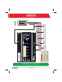
D.
Piedinatura dei connettori del sistema
Lo schema di seguito riporta la piedinatura dei connettori che permettono la connessione del sistema.
J5
RELAY
1) RELAY 1 - C
2) RELAY 1 - N.O
3) RELAY 2 - C
4) RELAY 2 - N.O
5) RELAY 3 - C
6) RELAY 3 - N.O
J17
S2
J12
120Ω TERM.
RS485/1
GROUND
1
2
3
4
5
RS485/1*
1) RTN
2) - T/R
3) +T/R
4) +5V
6
J15
RS485/2
1) RTN
2) - T/R
3) +T/R
4) +5V
4 3 2 1
S1
120Ω TERM.
RS485/2
4 3 2 1
J9
EXPANSION
BUS
1
J7
LAN
IEEE802.3u
2
2
J18
BATTERY IN
1) + Batt.
2) - Batt.
NOTE:
Only for dedicated
accessory
PVI-BATTERY-PACK
1
J8
Vin DC
1) + Vcc
2) - Vcc
INPUT DC:
24 Vdc (max. 48 Vdc)
0,3 A
NOTE:
Use the provided
power supply
1 2 3 4 5 6
J3
ANALOG INPUT
PT100/1000
1) PT_ALIM
2) PT_SENSE
3) PT_RTN
4) AIn_RTN
5) AIn 1
6) AIn 2
1 2 3 4 5 6
1 2 3 4 5 6
J20
DIGITAL I/O
1) DO_RTN_PWM1
2) DO_RTN_PWM2
3) DO_PWM 1
4) DO_PWM 2
5) DIn 1
6) DIn_RTN
J4
DIGITAL I/O
1) DIn 2
2) DIn 3
3) DIn 4
4) DIn_RTN
5) DIn 5 / CONT 2
6) DIn 6 / CONT 1
* Nel modello PVI-AEC-EVO LIGHT la porta RS485/1 (J17) non è disponibile per l acquisizione degli inverter,ma è utilizzabile unicamente
per l'acquisizione di parametri da contatori ISKRAEMECO dotati di interfaccia di comunicazione ModBus.
5 - IT
E.
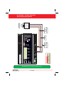
Collegamenti di alimentazione del sistema
1. Collegare l'alimentatore alla rete di alimentazione (100/240V - 50/60Hz):il led P ower dell'alimentatore si accenderà
stabilmente. Verificare che la tensione di uscita dell'alimentatore sia 24Vdc. Scollegare l'alimentatore dalla rete di
alimentazione.
2. Connettere la terra funzionale al PVI-AEC-EVO utilizzando il morsetto J12.
3. Collegare l'uscita dell'alimentatore alla morsettiera di alimentazione del PVI-AEC-EVO (rispettando la polarità)
utilizzando il cablaggio fornito a corredo.
4. Collegare l'alimentatore alla rete di alimentazione: dopo una prima fase di avvio (della durata di circa 30
secondi), durante la quale il sistema non è in grado di ricevere input da parte dell'utente, il led verde P ower ON
rimarrà stabilmente acceso.A display sarà visibile la scritta PVI-AEC-E VO.... (nella prima delle due righe) e data/ora
(nella seconda delle due righe).
-
-
+
+
Output DC
24V 0.75A
STEP POWER
DC
OK
Input AC
100-240V
L(+)
L(+)
2
1
N(-)
N(-)
-Vcc
+Vcc
50-60 Hz
100-240 V~
Nota: Il sistema deve essere alimentato unicamente con l'alimentatore ed il cavo fornito a corredo, pena il
decadimentodellacertificazioneCE.
6 - IT
IT - ITALIANO
Monitoring System
PVI-AEC-EVO / PVI-AEC-EVO LIGHT
GUIDA DI INSTALLAZIONE RAPIDA
F.
Impostazione di data ed ora
1. Accedere al menu principale come amministratore (Rif.Par. C ).
2. Accedere al menu “SETTINGS” > “DATALOGGER” quindi selezionare il sottomenu “SET DATE”. Sarà possibile
impostare la data corretta nel sistema.
3. Ritornare al menu “DATALOGGER” , quindi selezionare il sottomenu “SET TIME”. Sarà possibile impostare l'ora
corretta nel sistema.
SET PIN TO 0010
G.
PVI-AEC-EVO ......
12.00.00 01/01/11
ENTER
menu pin
0***
>settings
change password
ENTER
>set date
set time
ENTER
>set date
01/01/11
>set time
network
ENTER
>set time
12.00.00
>datalogger
io settings
NEXT
DIGIT
ENTER
CHANGE VALUE
NEXT
FIELD
ENTER
CHANGE VALUE
NEXT
FIELD
ENTER
CHANGE VALUE
ENTER
Collegamenti della linea RS485 e verifica
dell acquisizione degli inverter
Il collegamento della linea RS485 deve essere eseguito rispettando la piedinatura dei connettori J15 e/o J17.
Nota: Nella versione PVI-AEC-EVO LIGHT l unica porta RS485 utilizzabile per il monitoraggio degli inverter
è la porta RS485/2 contrassegnata dal connettore J15 .
Si consiglia di collegare la linea RS485 quando tutte le apparecchiature sono spente (sia il sistema di monitoraggio sia gli
inverter) e di mettere in servizio prima il sistema di monitoraggio e successivamente gli inverter. Si raccomanda di:
l
l
l
l
l
Utilizzare un cavo per applicazioni RS485 avente le seguenti caratteristiche:1 coppia twistata + 1 conduttore oppure
due coppie twistate, Schermo ed Impedenza caratteristica pari a 120Ω. Per maggiori informazioni in merito ad il
cavo da utilizzare fare riferimento all Appendice 2.
Accertarsi della corrispondenza dei segnali.
Accertarsi che tutte le tre linee (+T/R,-T/R e RTN) siano collegate in accordo agli schemi presenti nelle pagine 9 - 10.
Accertarsicheloschermodellalineadicomunicazionesiariferitoaterrainaccordoaglischemipresentinellepagine 9-10.
Accertarsi che ogni elemento della catena (ovvero ogni inverter oppure ogni modulo da 55kW) abbia un indirizzo
RS485 differente rispetto agli altri. Tale indirizzo è impostabile attraverso il display dell inverter.
7 - IT
Nota: Nel caso della versione PVI-AEC-EVO LIGHT gli indirizzi RS485 disponibili per gli inverter sono:
1, 2, 3, 4, 5 (negli inverter l indirizzo 1 corrisponde all impostazione AUTO ).
Nota: In caso di collegamento di più unità (inverter di stringa o/e moduli di conversione da 55kW) è
necessario cablare la linea di comunicazione RS485 in accordo allo schema daisy-chain
(entra-esci).
L ultimo inverter della catena daisy-chain deve essere terminato attivando la resistenza di
terminazione della linea di comunicazione da 120Ω, attraverso la commutazione del dip-switch
posto sulla scheda madre negli inverter di stringa, ed all interno di ogni framework negli inverter
centralizzati.
Nota: Il numero massimo di unità (inverter di stringa o/e moduli di conversione da 55kW) collegabili ad
una porta RS485 del PVI-AEC-EVO è 62; per collegare un numero maggiore di 62 unità è necessario
utilizzare la seconda porta RS485/2 rispettando lo stesso schema di collegamento utilizzato per la
porta RS485/1 principale.
Nella versione PVI-AEC-EVO LIGHT il numero di inverter monitorabili è limitato ad un massimo di 5
inverter di stringa i quali sono collegabili unicamente alla porta RS485/2 (Rif. Par. D). I modelli
compatibili (in tutte le loro varianti) per la versione PVI-AEC-EVO LIGHT sono: PVI-2000(-OUTD); UNO2.0/2.5-I-OUTD; PVI-3600; PVI-3.0/3.6/4.2-TL-OUTD; PVI-3.8/4.6-I-OUTD; PVI-5000/6000-TL-OUTD;
PVI-10.0/12.5-TL-OUTD; PVI-10.0/12.0-I-OUTD.
Nota: Nel caso di impianti misti, la compresenza di inverter di stringa e di inverter centralizzati sulla
stessa linea RS485 è permessa. Per cablare tale linea è necessario rispettare tutte le indicazioni
precedenti.
Nota: In tutti gli inverter di stringa (ad eccezione dei modelli PVI-5000/6000-TL-OUTD) è presente un
morsetto chepermettedidarecontinuitàalloschermodelcavodellalineaRS485.
NegliinvertermonofasetalemorsettoèindicatoconladicituraLNK,neitrifaseèindicatoconSCLD.
Nota: Negli inverter centralizzati è disponibile un morsetto, presente nella morsettiera dei segnali ed
indicato con X23 , che permette di collegare a terra lo schermo di ogni singola porzione di linea di
comunicazione indipendentemente dalle altre porzioni (non deve essere quindi data continuità
allo schermo del cavo ).
Nota: Per ulteriori dettagli in merito alla cablatura della linea RS485 e/o all attivazione delle resistenze
di terminazione, fare riferimento al manuale utente degli inverter di stringa e al manuale utente
degli inverter centralizzati.
8 - IT
IT - ITALIANO
Monitoring System
AURORA
9 - IT
+T/R
RTN
RS485
+T/R
-T/R
ON
OFF
120Ω
Term.
Resistor
ON
OFF
120Ω TERM.
RESISTOR ON
120Ω TERM.
RESISTOR
RTN
RTN +T/R -T/R
RS485
-T/R
AURORA
-T/R
+T/R
RTN
-T/R
ON
OFF
ON
OFF
120Ω
Term.
Resistor
120Ω TERM.
RESISTOR
RTN
120Ω TERM.
RESISTOR OFF
RTN +T/R -T/R
RS485
+T/R
RS485
+T/R
RS485
ON
OFF
120Ω
Term.
Resistor
4 3 2 1
120Ω TERM.
RESISTOR ON
4 3 2 1
RTN
+T/R
-T/R
Nota: Accertarsicheogni
inverterdellacatenaabbia
unindirizzoRS485differente
rispettoaglialtri.
Nel casodellaversione
PVI-AEC-EVOLIGHTgliindirizzi
RS485disponibilipergliinverter
sono:1,2,3,4,5 (negliinverter
l’indirizzo1corrisponde
all’impostazione“AUTO”).
PVI-AEC-EVO / PVI-AEC-EVO LIGHT
GUIDA DI INSTALLAZIONE RAPIDA
RTN
-T/R
AURORA
10 - IT
A
A
X20 X21 X22 X23 X24 X25 X26 X27
D
D
X20 X21 X22 X23 X24 X25 X26 X27
X20 X21 X22 X23 X24 X25 X26 X27
RTN +T/R -T/R
A
RTN +T/R -T/R
D
A
120Ω TERM.
RESISTOR OFF
D
X20 X21 X22 X23 X24 X25 X26 X27
120Ω TERM.
RESISTOR ON
A
D
X20 X21 X22 X23 X24 X25 X26 X27
120Ω TERM.
RESISTOR OFF
4 3 2 1
RTN
+T/R
-T/R
IT - ITALIANO
4 3 2 1
120Ω TERM.
RESISTOR ON
Nota: Accertarsi che ogni
modulo da 55 kW della
catena abbia un indirizzo
RS485 differente rispetto agli
altri.
Monitoring System
PVI-AEC-EVO / PVI-AEC-EVO LIGHT
GUIDA DI INSTALLAZIONE RAPIDA
Dopo aver effettuato queste verifiche, mettere in servizio prima il sistema di monitoraggio e successivamente gli
inverter. Il sistema effettua automaticamente la scansione del bus RS485 e quindi rileva in automatico gli inverter
presenti. Per verificare la presenza degli inverter,si può agire direttamente da display.
1. Accedere al menu principale come amministratore (Rif.Par. C ) .
2. Accedere al menu “CURRENT VALUES” > “ENERGY INVERTERS” (per visualizzare gli inverter di stringa) e/o
“CURRENT VALUES” > “ENERGY RACK” (per visualizzare i moduli di conversione da 55kW). Verrà visualizzato il
numero degli inverter individuati nella scansione; scorrendo con i tasti freccia (
) sarà possibile
visualizzare la lista degli inverter monitorati identificati dal Serial Number (S/N).
SET PIN TO 0010
PVI-AEC-EVO ......
12.00.00 01/01/11
ENTER
>CURRENT VALUE
SETTINGS
ENTER
>ENERGY INVERTERS
ENERGY RACK
ENTER
>ENERGY RACK
ENERGY PLANT
ENTER
menu pin
0***
CHANGE VALUE
30 INVERTERS
>INVERTER SN 123456
RACK
>RACK
NEXT
DIGIT
ENTER
CHANGE
INVERTER
N. 1
SN 123456
CHANGE
RACK
Nota: Il tempo impiegato dal PVI-AEC-EVO per effettuare la scansione ed acquisire gli inverter può variare
dipendentemente dal numero degli inverter presenti sulla stessa linea (talvolta alcuni minuti).
H.
Configurazione degli ingressi analogici
Il collegamento dei sensori analogici deve essere effettuato rispettando la piedinatura del connettore J3.
Il sistema dispone di due ingressi di tipo 0-10 Vdc, ed un ingresso di tipo PT100/1000.
Nota: Per ogni ingresso analogico (sia del tipo 0-10 Vdc che PT100/1000) è possibile connettere un solo
sensore analogico. Non è quindi possibile connettere più sensori sullo stesso ingresso analogico.
Relativamente al collegamento di sensori del tipo PT100/1000, il sistema è in grado di effettuare la lettura dei
sensori attraverso il collegamento di tre fili:
l Una linea di alimentazione del sensore (PT_ALIM);
l Una linea di lettura (PT_SENSE)
l Una linea di richiusura dell'alimentazione e della lettura (PT_RTN).
11 - IT
La misura viene effettuata tra PT_SENSE e PT_RTN; l'elemento di misura deve essere cablato tra questi due segnali.
Il sensore PT100/PT1000 viene automaticamente riconoscuito dal sistema e quindi acquisito senza necessità di ulteriori
impostazioni.
In merito al collegamento dei sensori con range di uscita 0...10Vdc,questi devono essere alimentati e l'alimentazione può
essere prelevata direttamente dall'alimentazione del sistema; la massa dell'alimentazione e la massa di lettura dei
segnali è a comune.
Per il collegamento del sensore, oltre all'alimentazione, è necessario collegare il segnale proporzionale alla grandezza
misurata ad uno dei due ingressi analogici disponibili (AIn1/AIn2).
Lamassadelsegnaledimisura,qualoradifferentedallamassadell'alimentazione,deveesserecollegataalmorsettoAIn_RTN.
Dopo aver effettuato le connessioni è necessario configurare il sensore nel sistema in modo da acquisire correttamente la
grandezza:
1. Accedere al menu principale come amministratore (Rif.Par. C ) .
2. Accedere al menu “SETTINGS” > “IOSETTINGS”.
3. Selezionare la voce “ANALOG INPUT1” e selezionare quindi il modello di sensore collegato all'ingresso AIn1 del
sistema (il modello selezionato verrà identificato con un asterisco (*) ).
4. Selezionare la voce “ANALOG INPUT2” e selezionare quindi il modello di sensore collegato all'ingresso AIn2 del
sistema (il modello selezionato verrà identificato con un asterisco (*) ).
Nota: In caso di collegamento di sensori PT100/1000 con due soli terminali, collegare un terminale al
morsetto PT_SENSE ed un terminale al morsetto PT_RTN; realizzare poi un ponticello tra PT_ALIM
e PT_SENSE.
SET PIN TO 0010
PVI-AEC-EVO ......
12.00.00 01/01/11
ENTER
menu pin
0***
>settings
change password
ENTER
>io settings
UPGRADE FIRMWARE
>ANALOG INPUT1
ANALOG INPUT2
ENTER
>ANALOG INPUT1
T1000-INTEGR
*
>ANALOG INPUT2
PULSE IN1
ENTER
>ANALOG INPUT2
RAD-13TC
*
12 - IT
CHANGE VALUE
NEXT
DIGIT
ENTER
CHANGE
SENSORS
ENTER
CHANGE
SENSORS
ENTER
ENTER
IT - ITALIANO
Monitoring System
PVI-AEC-EVO / PVI-AEC-EVO LIGHT
GUIDA DI INSTALLAZIONE RAPIDA
1. Accedere al menu principale come amministratore (Rif.Par. C ) .
2. Accedere al menu “CURRENT VALUES” > “ANALOG VALUE”. Verrà visualizzato il valore della grandezza per
ciascuno degli ingressi analogici.
SET PIN TO 0010
PVI-AEC-EVO ......
12.00.00 01/01/11
ENTER
menu pin
0***
>CURRENT VALUE
SETTINGS
ENTER
>ANALOG VALUE
DIGITAL VALUE
>T1000-INTEGR
20.0 DEGC
CHANGE VALUE
NEXT
DIGIT
ENTER
ENTER
AN1
CHANGE
INPUT
Nota: Nella tabella di seguito si riporta la lista dei sensori presenti nel sistema ed offerti a catalogo PowerOne. PerlaconnessioneditalisensorifareriferimentoaglischemipresentiinAppendice1.
SENSORI CON USCITA ANALOGICA COMPATIBILI CON PVI-AEC-EVO (A CATALOGO POWER-ONE)
MODELLO
TIPOLOGIA
IDENTIFICATIVO
DISPLAY
RANGE
OPERATIVO
PVI-AEC-IRR
Sensore Irraggiamento (W/m --> V)
IRR
0-1200 W/m
PVI-AEC-IRR-T
Sensore Irraggiamento con sensore
2
Temperatura cella integrato (W/m / °C --> V)
IRR-T_Irr /
IRR-T_Temp
0-1200 W/m
-20 to +80 °C
PVI-AEC-T100-ADH
Sensore di temperatura modulo (back cell)
PT100 adesivo
T100-ADH
-50 to +150 °C
PVI-AEC-T1000-INTEGR
Sensore di temperatura ambiente con
convertitore 0...10Vdc integrato (°C --> V)
T1000-INTEGR
-50 to +50 °C
PVI-AEC-T1000-BOX
Sensore di temperatura ambiente PT1000
T1000-BOX
-50 to +50 °C
2
2
2
2
PVI-AEC-PYR-1300
Piranometro ( W/m --> V)
Pirano_0-20mA
0-1300 W/m
PVI-AEC-WIND-COMPACT
Sensore velocità vento (m/s --> V)
WIND-COMPACT
0 - 50 m/s
2
Nota: Il sistema è predisposto per il collegamento di altri sensori disponibili in commercio: Piranometro
ZippZonen0-1600W/m2 e piranomentro0-2000W/m2.
13 - IT
IT - ITALIANO
Per leggere le misure dei sensori e verificare la loro correttezza:
IT - ITALIANO
I.
Configurazione del sistema per la connessione
in rete LAN (porta Ethernet)
La connessione del PVI-AEC-EVO al PC può essere effettuata attraverso connessione diretta tramite cavo ethernet, oppure
connettendo entrambi i dispositivi ad una rete locale LAN (attraverso router,hub o switch).
In caso di connessione diretta è sufficiente connettere tra loro i due dispositivi attraverso un cavo ethernet e configurare i
parametri di rete del PVI-AEC-EVO e del PC per far si che siano compatibili tra loro.
Nota: L'indirizzo IP del PC e l'indirizzo IP del PVI-AEC-EVO devono appertenere allo stesso gruppo ma non
devonoessereidentici,adesempio:
INDIRIZZO IP DEL PC: 20.200.200.1
INDIRIZZO IP DEL PVI-AEC-EVO: 20.200.200.24
La subnet mask deve essere la stessa in entrambi i dispositivi, ad esempio: 255.0.0.0
In caso di connessione ad una rete locale LAN preesistente si rende necessario assegnare al PVI-AEC-EVO dei parametri di
rete compatibili con la rete locale al quale il PVI-AEC-EVO è connesso. Fare riferimento all amministratore di rete per
ottenere i corretti parametri di rete.
MODIFICA DEI PARAMETRI DI RETE DEL PC
Per modificare i parametri di rete del PC,selezionare Start quindi Pannello di controllo quindi cliccare su Connessioni
di rete : la nuova finestra aperta mostrerà le connessioni di rete presenti; cliccare con il tasto destro del mouse su
Connessioneallaretelocale e selezionare Proprietà ;si aprirà la finestra mostrata nella figura sottostante.
Windows XP
Windows 7/8
Selezionare Protocollo Internet (TCP/IP) (o Protocollo Internet versione 4 (TCP/IPv4) in Windows 7/8) e cliccare
sul tasto Proprietà .
14 - IT
IT - ITALIANO
Monitoring System
PVI-AEC-EVO / PVI-AEC-EVO LIGHT
GUIDA DI INSTALLAZIONE RAPIDA
Selezionare l opzione Utilizza il seguente indirizzo IP ed inserire i parametri di rete (Indirizzo IP,Subnet Mask,Gateway)
compatibili con i parametri di rete configurati nel PVI-AEC-EVO.
I campi relativi al DNS possono essere lasciati vuoti.
Nota: In caso di connessione diretta tra PVI-AEC-EVO e PC si consiglia di non configurare il parametro
Gateway .
Nota: La procedura indicata è da considerasi di solo esempio per i sistemi operativi più diffusi.
15 - IT
Monitoring System
IT - ITALIANO
MODIFICA DEI PARAMETRI DI RETE DEL PVI-AEC-EVO
Per modificare i parametri di rete del PVI-AEC-EVO seguire la procedura sottostante:
1. Alimentare il sistema ed attendere il completamento della fase di avvio (Rif.Par. E ).
2. Accedere al menu principale come amministratore (Rif.Par. C ) .
3. Accedere al menu “SETTINGS” > “DATALOGGER” > “NETWORK”. Attraverso le voci del menu “NETWORK” sarà
possibile modificare i parametri di connessione alla rete LAN (Indirizzo IP, Subnet Mask, Gateway) in modo da
configurare il sistema per la connessione in rete e/o per la connessione diretta ad un PC.
4. Al termine delle operazioni di impostazione,ritornare alla schermata principale,quindi spegnere e riaccendere
il sistema per rendere effettive le impostazioni.
SET PIN TO 0010
PVI-AEC-EVO ......
12.00.00 01/01/11
ENTER
menu pin
0***
>settings
change password
ENTER
>datalogger
io settings
>NETWORK
SET DATA
ENTER
>IP SETTING
SUBNET MASK
ENTER
>IP SETTING
XXX.XXX.XXX.XXX
>SUBNET MASK
ip gateway
ENTER
>subnet mask
XXX.XXX.XXX.XXX
>IP gateway
ip method
ENTER
>IP gateway
XXX.XXX.XXX.XXX
16 - IT
NEXT
DIGIT
ENTER
CHANGE VALUE
NEXT
DIGIT
ENTER
CHANGE VALUE
NEXT
DIGIT
ENTER
CHANGE VALUE
NEXT
DIGIT
ENTER
CHANGE VALUE
ENTER
PVI-AEC-EVO / PVI-AEC-EVO LIGHT
GUIDA DI INSTALLAZIONE RAPIDA
L.
Accesso al Webserver interno
Per accedere alle pagine di Webserver del sistema dopo aver effettuato la connessione del sistema alla rete locale
LAN oppure diretta al PC,aprire un browser internet (es.Internet Explorer) e digitare nella barra degli indirizzi:
http://<indirizzo IP del sistema>
Nota: Per accedere alle pagine di webserver è necessario inserire username e password:
USERNAME: admin
PASSWORD: admin
Dopo aver effettuato l accesso al Webserver interno accedere alla pagina di configurazione (CONFIG) dell'impianto
(PLANT) ed inserire le coordinate GPS dell'installazione secondo uno dei seguenti formati:
Indicatore
Gradi
Punto
Latitudine
N43.33
N
43
.
Gradi (centesimi di grado)
33
Longitudine
E11.35
E
11
.
35
Gradi
Indicatore
Primi
Apice
Secondi
Doppio Apice*
Latitudine
43N50’20”
43
N
50
‘
20
“
Longitudine
11E23’30”
11
E
23
‘
30
“
* Il carattere Doppio Apice ( ”) deve essere inserito immettendo due volte il carattere apice ( ’).
Nota: L impostazione delle coordinate GPS è di fondamentale importanza per permettere il corretto
funzionamento del sistema di monitoraggio.
17 - IT
Per permettere al PVI-AEC-EVO di comunicare con il portale web Aurora Vision, accedere alla pagina di configurazione
(CONFIG) della rete (NETWORK) e verificare che nella sezione DATA TRANSFER alla voce Ip Address Portal si trovi
l indirizzo IP 63.236.63.180 .
Nota: Qualora l impostazione Ip Portal Address non corrisponda a 63.236.63.180, modificarla
immettendo tale indirizzo e premere su Confirm per renderla attiva. Successivamente a questa
operazione,effettuare il reset del sistema (ON-OFF).
Nota: Per rendere completamente funzionante il sistema è indispensabile che il sistema stesso sia
continuativamente connesso ad internet in modo da poter dialogare con il server di Power-One per
le operazioni di visualizzazione grafica dei dati su pagine web oltre che per l'invio di messaggi di
allarme e/o di report. Affinchè il PVI-AEC-EVO sia in grado di dialogare con il server di gestione del
portale,è indispensabile che la rete LAN nella quale il PVI-AEC-EVO è cablato sia tale da permettere
la connessione all'indirizzo IP 63.236.63.180 attraverso la porta 80.
18 - IT
IT - ITALIANO
Monitoring System
PVI-AEC-EVO / PVI-AEC-EVO LIGHT
GUIDA DI INSTALLAZIONE RAPIDA
19 - IT
Monitoring System
Identificazione del MAC Address
Durante il processo di associazione dei PVI-AEC-EVO in AuroraVision verrà richiesto di inserire i MAC Address dei PVI-AECEVO presenti in impianto.
E possibile ricavare il MAC Address del proprio PVI-AEC-EVO osservando l etichetta presente sul lato destro del prodotto.Il
MAC Address è composto dai 12 caratteri (separati da due punti) indicati in rosso nella figura di esempio sottostante.
PVI-AEC-EVO
P-1 P/N: 3I72001F100G
Prod. Week 16/11
S/N: 3I72001F100G 000464VI1611
MAC ADDRESS: 00:50:C2:42:38:24
In alternativa è possibile ricavare il MAC Address attraverso il display:
1. Accedere al menu principale come amministratore (Rif.Par. C ).
2. Accedere al menu “INFORMATION” > “PRODUCT”.
3. Utilizzando i tasti freccia (
) scorrere fino alla schermata “MACADDRESS”.
SET PIN TO 0010
PVI-AEC-EVO ......
12.00.00 01/01/11
ENTER
menu pin
0***
>INFORMATION
CURRENT VALUE
ENTER
>PRODUCT
NETWORK
pN
3I72
CHANGE
MENU
MAC ADDRESS
00:50:C2:42:38:24
20 - IT
CHANGE VALUE
ENTER
NEXT
DIGIT
ENTER
IT - ITALIANO
M.
PVI-AEC-EVO / PVI-AEC-EVO LIGHT
GUIDA DI INSTALLAZIONE RAPIDA
N. Aggiornamento Firmware
E possibile eseguire l aggiornamento del Firmware del PVI-AEC-EVO sia localmente utilizzando la SD Card,sia da remoto
utilizzando il portale web AuroraVision.
Nota: L aggiornamento del firmware attraverso SD Card deve essere effettuato solo nel caso in cui non sia
possibile effettuare l aggiornamento del firmware attraverso il portale web Aurora Vision.
Nota: Per dettagli sulla procedura di aggiornamento del firmware attraverso portale web Aurora Vision,
fare riferimento alla documentazione presente sul sito web www.Auroravision.net.
La procedura di aggiornamento firmware attraverso SD Card è la seguente:
1. Accedere al display inserendo la password di utente 0000.
2. Verificare e annotare la versione correntemente installata dei firmware:
Firmware AVR:
Firmware Display:
Firmware IO:
Information > Product > Firmware AVR
Information > Product > Firmware Display
Information > Product > Firmware IO
3. Spegnere il PVI-AEC-EVO e attendere almeno un minuto.
4. Disconnettere dal PVI-AEC-EVO tutte le connessioni presenti (Linea/e RS485,connessione LAN,sensori).
5. Estrarre la SD Card dallo slot posto sul pannello frontale del PVI-AEC-EVO esercitando una leggera
pressione sulla SD Card.
6. Inserire la SD Card nel lettore di SD Card oppure nello slot per lettura della SD Card del PC
7. Eliminare le cartelle upgrade,web,lang e config dalla SD Card.
8. Copiare nella radice della SD Card le nuove cartelle upgrade,web,lang e config.
9. Estrarre la SD Card dal lettore di SD Card oppure dallo slot per la lettura di SD Card.
10. Inserire la SD Card nell'apposito slot posto sul pannello frontale del PVI-AEC-EVO esercitando una
leggera pressione sulla SD Card in modo da favorirne il bloccaggio.
11. Accendere il PVI-AEC-EVO e attendere circa un minuto.(N.B. l interruzione dell alimentazione durante la fase di
aggiornamento può provocare gravi danni al dispositivo).
12. Accedere a display inserendo la password di amministratore 0010.
13. Accedere al menu SETTINGS” > “UPGRADE FIRMWARE” > “UPGRADE AVR” > Confirm per procedere; attendere il
completamento dell'aggiornamento ed il successivo riavvio.Il processo di riavvio sarà completato quando a display
sarà visualizzata la schermata di data/ora.
14. Accedere a display inserendo la password di amministratore 0010.
21 - IT
15. Accedere al menu SETTINGS” > “UPGRADE FIRMWARE” > “UPGRADE ADC” > Confirm per procedere; attendere il
completamento dell'aggiornamento. Il processo di aggiornamento sarà completato quando a display sarà
visualizzato il messaggio “UpgradeSuccess”.
16. Accedere al menu SETTINGS” > “UPGRADE FIRMWARE” > “UPGRADE DISPLAY” > Confirm per procedere; attendere il
completamento dell'aggiornamento. Il processo di aggiornamento sarà completato quando a display sarà
visualizzato il messaggio “UpgradeSuccess”.
17. Accedere al menu SETTINGS” > “UPGRADE CONFIG” > Confirm per procedere; attendere il completamento
dell'aggiornamento.Il processo di aggiornamento sarà completato quando a display verrà nuovamente visualizzato
il menu “UPGRADECONFIG”.
18. Spegnere il sistema; ripristinare tutte le connessioni (linea/e RS485, connessione LAN, sensori), quindi riavviare il
sistema.
22 - IT
IT - ITALIANO
Monitoring System
PVI-AEC-EVO / PVI-AEC-EVO LIGHT
SCHNELLINSTALLATIONSANLEITUNG
INHALTSVERZEICHNIS
A.
Beschreibung des Produkts
2
B.
Packungsinhalt
3
C.
Benutzerschnittstelle und Verwendung des Displays
4
D.
Pinbelegung der Systemstecker
5
E.
Versorgungsanschlüsse und Einschaltung des Systems
6
F.
Einstellung von Datum und Uhrzeit
7
G.
Anschlüsse der Leitung RS485 und Überprüfung der Erfassung der Wechselrichter
7
H.
Konfiguration der Analogeingänge
11
I.
Konfiguration des Systems für den Anschluss an das LAN-Netzwerk (Ethernet-Port)
14
L.
Zugriff zum Internen Webserver
17
M.
Identifizierung der MAC-Adresse
20
N.
Firmware Update
21
Anhänge
1)
2)
3)
4)
Schaltbilder der Sensoren
Eigenschaften des RS485-Kabels
Display flow-charts
Compliance-Anforderungen
1 - DE
Monitoring System
A.
Beschreibung des Produkts
Mit dem Produkt können die Parameter von Wechselrichtern und Stringcombs (je nach Aufbau der Überwachung
der zentralisierten Wechselrichter) über die Leitung RS485 mit dem proprietären Protokoll von Power-One erfasst
werden.
Das System verfügt über zwei gleichwertige Ports RS485, mit denen jeweils eine Erfassung von 62 StringWechselrichtern oder 62 Wandlungsmodulen mit 55kW möglich ist (Modulare Zentral Inverter); es ist desweiteren
moeglich den Kommunikationsport RS485/1 (ref.Im Kapitel D) fuer die Uebertragung / Empfang der Parameter von
den Sektoren ISKRAMECO MT831 welche mit den Kommunikationsinterface Modbus.
Hinweis:Mitdem PVI-AEC-EVOLIGHTkönnenmaximal5Stringinverterüberwachtwerdenund koennennurmit
PortRS485/2verbundenwerden.(ref.par/D). NurdasFolgende(inallenihrenVarianten)isterlaubt:
PVI-2000(-OUTD)
UNO-2.0/2.5-I-OUTD
PVI-3600
PVI-3.0/3.6/4.2-TL-OUTD
PVI-3.8/4.6-I-OUTD
PVI-5000/6000-TL-OUTD
PVI-10.0/12.5-TL-OUTD
PVI-10.0/12.0-I-OUTD
( * ): Kompatibel auch mir vorhergehenden nationalen Versionen ( z.B.: PVI-3.6-OUTD-DE)
In der Version PVI-AEC EVO Light das Kommunikationsport RS485/1 (Ref. Par. D) kann nur zur
Uebertragung / Empfang von Parametern der Sektoren ISKRAMECO MT831 ausgeruestet mit
Kommunikationsinterface Modbus.
Das System verfügt über drei Analogeingänge für den Anschluss von Sensoren für die Messung der
Umweltparameter: Power-One bietet in seinem Katalog ein komplettes Angebot von Sensoren für
Sonneneinstrahlung,Umbebungstemperatur und der Zelle,Geschwindigkeit und Luftrichtung an.
Das System umfasst auch sechs Digitaleingänge für die Erfassung von Statussignalen (beispielsweise Hilfskontakte
von Leistungsschaltern),denen die Status-Alarmbedingungen zugeordnet sind.
Als Benutzerschnittstelle bietet das System ein Display mit 2x16 Zeichen und vier Tasten sowie einen integrierten
Internetserver mit html-Seiten über eine LAN-Verbindung.
Die Anfangskonfiguration des Systems (Überprüfung der Erfassung der Parameter von Wechselrichtern,
Konfiguration der Analogeingänge, Konfiguration der Parameter des LAN-Netzwerks) kann vollständig über das
Display und die Tasten vorgenommen werden; Für die Anzeige der Detail-Parameter der Wechselrichter und/oder
der Anschlusskasten sowie für die erweiterten Konfigurationen ist die Öffnung der Seiten des integrierten InternetServers erforderlich.
Der PVI-AEC-EVO arbeitet in Verbindung mit dem Service-Webportal Aurora Vision: durch die Registrierung für diesen
Service ist es moeglich, die Überwachung und Management ueber Remote die Systeme mit Ihrem Account zu
verknuepfen.
DasWebportal AuroraVision finden Sie auf derWebsite:
www.Auroravision.net
2 - DE
DE - DEUTSCH
Beim PVI-AEC-EVO handelt es sich um ein Überwachungs- und Kontrollsystem für Photovoltaikanlagen, die mit
Produkten Power-One Aurora produzient wurden. Bei der weiteren Vorgehensweise werden wir vom SYSTEM
reden,damit sind beide Versionen gemeint wenn nicht spezifisch auf eine bestimmte Variante hingewiesen wird.
PVI-AEC-EVO / PVI-AEC-EVO LIGHT
SCHNELLINSTALLATIONSANLEITUNG
B.
Packungsinhalt
1
AURORA PVI-AEC-EVO / PVI-AEC-EVO LIGHT
2
Stromversorgung 100-240Vac 50-60Hz / 24Vdc
3
Stromversorgungskabel
4
Handbuch Schnellinstallation
5
SD Karte (montiert)
6
Gegenstecker I/O Anschlüsse (montiert)
7
Gegenstecker RS485 Anschlüsse (montiert)
8
Gegenstecker Relaisanschlüsse (montiert)
9
Gegenstecker Stromversorgung (montiert)
1
2
3
4
-
-
+
+
Output DC
24V 0.75A
STEP POWER
DC
OK
Input AC
100-240V
L(+)
N(-)
5
6
7
8
9
Hinweis:Bitte überprüfen den Inhalt der Packung gemäss obiger Liste. Bitte überprüfen Sie ob die
Schachtel der Inhalt keine Beschädigung aufweist. Im Falle von Beschädigung wenden Sie sich
an die Transportfirma und durch zeitgerechter Mitteilung technischen Serviceunterstuetzung
oder den Kundendienst Power-One in Anbetracht der Stoerungstypologie.
3 - DE
Monitoring System
C.
Benutzerschnittstelle und Verwendung des Displays
Die Anfangskonfiguration des Systems (Überprüfung der Erfassung der Parameter von Wechselrichtern,
Konfiguration der Analogeingänge, Konfiguration der Parameter des LAN-Netzwerks) kann über das Display und
die Tasten an der Frontabdeckung vorgenommen werden.
Für die Anzeige der Detail-Parameter der Wechselrichter und/oder der Anschlusskasten sowie für die erweiterten
Konfigurationen ist der Zugang zum internen Internet-Server erforderlich. Dabei sind die im Abschnitt L
beschriebenen Schritte auszuführen.
Eine Liste der über das Display zugänglichen Funktionen ist in der Tabelle im Anhang 3 aufgeführt.
VERWENDUNG DER TASTEN
Taste "Enter". Diese Taste wird verwendet, um eine Aktion zu bestätigen, um ins Hauptmenü oder in
das Untermenü eines der ausgewählten Menüpunkte (durch das Symbol > angezeigt) zu gelangen
oder um zur folgenden Ziffer die zu ändern ist zu springen.
Taste "Down". Diese Taste wird verwendet, um die Menüpunkte nach unten zu scrollen oder um die
numerische Skala absteigend zu sortieren.
Taste "Up". Diese Taste wird verwendet, um die Menüpunkte nach oben zu scrollen oder um die
numerische Skala aufsteigend zu sortieren.
Taste "Esc". Diese Taste wird verwendet, um in das vorherige Menü zu gelangen oder um zur
vorgehenden Ziffer,die zu ändern ist,zurückzukehren.
Zugriff auf das Hauptmenü mit Administrator-Rechte
Um die Anfangskonfigurationen vorzunehmen, wir der Zugang als Administrator zu den verschiedenen Menüs
benötigt. Die Taste ENTER (
) drücken und das Passwort 0010 eingeben: Für die Eingabe des Passworts die
Pfeiltasten (
) drücken,um den Wert zu ändern,dann die Taste ENTER drücken,um den Wert zu bestätigen.
Mit diesem Passwort ist der Zugriff auf alle Einstellung-Untermenüs des Systems vom Displays möglich.
4 - DE
DE - DEUTSCH
Das System verfügt über ein Display mit 2x16 Zeichen, vier Tasten zum Navigieren in den Menüs und drei LEDs zur
Statusanzeige des Geräts.
PVI-AEC-EVO / PVI-AEC-EVO LIGHT
SCHNELLINSTALLATIONSANLEITUNG
D.
Pinbelegung der Systemstecker
Im nachfolgend aufgeführten Schema werden die Pin-out der Stecker gezeigt, mit denen das System
angeschlossen wird.
J5
RELAY
1) RELAY 1 - C
2) RELAY 1 - N.O
3) RELAY 2 - C
4) RELAY 2 - N.O
5) RELAY 3 - C
6) RELAY 3 - N.O
J17
S2
J12
120Ω TERM.
RS485/1
GROUND
1
2
3
4
5
RS485/1*
1) RTN
2) - T/R
3) +T/R
4) +5V
6
J15
RS485/2
1) RTN
2) - T/R
3) +T/R
4) +5V
4 3 2 1
S1
120Ω TERM.
RS485/2
4 3 2 1
J9
EXPANSION
BUS
1
J7
LAN
IEEE802.3u
2
2
J18
BATTERY IN
1) + Batt.
2) - Batt.
NOTE:
Only for dedicated
accessory
PVI-BATTERY-PACK
1
J8
Vin DC
1) + Vcc
2) - Vcc
INPUT DC:
24 Vdc (max. 48 Vdc)
0,3 A
NOTE:
Use the provided
power supply
1 2 3 4 5 6
J3
ANALOG INPUT
PT100/1000
1) PT_ALIM
2) PT_SENSE
3) PT_RTN
4) AIn_RTN
5) AIn 1
6) AIn 2
1 2 3 4 5 6
J20
1 2 3 4 5 6
DIGITAL I/O
1) DO_RTN_PWM1
2) DO_RTN_PWM2
3) DO_PWM 1
4) DO_PWM 2
5) DIn 1
6) DIn_RTN
J4
DIGITAL I/O
1) DIn 2
2) DIn 3
3) DIn 4
4) DIn_RTN
5) DIn 5 / CONT 2
6) DIn 6 / CONT 1
*Beim Modell PVI-AEC-EVO-LIGHT kann der Kommunikationsport RS485/1 (J17) nicht fuer die Inverteruebertragung benutzt
werden aber nur fuer die Uebertragung / Empfang der Sektoren ISKRAEMECO ausgeruestet mit Kommunikationsinterface Modbus.
5 - DE
Monitoring System
E.
Versorgungsanschlüsse und Einschaltung des Systems
2. Verbinden Sie die Funktionserde an den PVI-AEC-EVO mit Klemme J12.
3. Den Ausgang des Stromversorgungsgeräts an das Versorgungs-Klemmenbrett des PVI-AEC-EVO
polaritätsrichtig unter Verwendung der im Lieferumfang enthaltenen Verkabelung anschließen.
4. Das Stromversorgungsgerät an das Stromnetz anschließen: nach einer ersten Startphase (Dauer ca. 30
Sekunden) während der das System keinen Input vom Benutzer empfangen kann, leuchtet die grüne LED
PowerOn dauerhaft auf. Auf dem Display werden die Angaben PVI-AEC-EVO.... (in der ersten der beiden
Zeilen) sowie das Datum/Uhrzeit (in der zweiten der beiden Zeilen) angezeigt.
-
-
+
+
Output DC
24V 0.75A
STEP POWER
DC
OK
Input AC
100-240V
L(+)
L(+)
2
1
N(-)
N(-)
-Vcc
+Vcc
50-60 Hz
100-240 V~
Hinweis: Bitte nur den im System mitgelieferten Anschlusstecker benutzen andernfalls verfaellt die CE
Zertifikation.
6 - DE
DE - DEUTSCH
1. Das Stromversorgungsgerät an das Versorgungsnetz (100/240V 50/60Hz) anschließen: die LED Power des
Stromversorgungsgeräts leuchtet dauerhaft auf. Überprüfen, ob die Ausgangsspannung des
Stromversorgungsgeräts 24Vdc beträgt. Das Stromversorgungsgerät vom Versorgungsnetz abnehmen.
PVI-AEC-EVO / PVI-AEC-EVO LIGHT
SCHNELLINSTALLATIONSANLEITUNG
F.
Einstellung von Datum und Uhrzeit
1. Das Hauptmenü als Administrator (siehe Abschn. C ) öffnen.
2. Das Menü “SETTINGS” > “DATALOGGER” öffnen und das Untermenü “SET DATE” anwählen. Das korrekte Datum des
Systems kann eingestellt werden.
3. In das Menü “DATALOGGER” zurückkehren und das Untermenü “SET TIME” anwählen. Die korrekte Uhrzeit des
Systems kann eingestellt werden.
SET PIN TO 0010
G.
PVI-AEC-EVO ......
12.00.00 01/01/11
ENTER
menu pin
0***
>settings
change password
ENTER
>set date
set time
ENTER
>set date
01/01/11
>set time
network
ENTER
>set time
12.00.00
>datalogger
io settings
NEXT
DIGIT
ENTER
CHANGE VALUE
NEXT
FIELD
ENTER
CHANGE VALUE
NEXT
FIELD
ENTER
CHANGE VALUE
ENTER
Anschlüsse der Leitung RS485 und Überprüfung der
Erfassung der Wechselrichter
DerAnschlussderLeitungRS485mussunterBeachtungderPinbelegungderSteckerJ15und/oderJ17vorgenommenwerden.
Hinweis: BeimPVI-AEC-EVOLIGHTkannnurderRS485/2Anschluss(SteckerJ15)verwendetwerden.
Es wird empfohlen, die Leitung RS485 anzuschließen, wenn alle Geräte ausgeschaltet sind (sowohl das
Überwachungssystem als auch die Wechselrichter), und zuerst das Überwachungssystem und nachfolgend die
Wechselrichter in Betrieb zu nehmen.Folgendes wird empfohlen:
l Ein RS485-Kabel mit folgenden Eigenschaften verwenden: 1 verdrilltes Paar + 1 Leiter oder zwei gedrillte Paare,
Abschirmung und 120Ω Impedanz. Für weitere Informationen über das zu verwendende Kabel siehe Anhang 2.
l Sicherstellen,dass die Signale übereinstimmen.
l Sicherstellen,dass alle drei Leitungen (+T/R,-T/R und RTN) nach den Bilder der Seiten 9 - 10 angeschlossen sind.
l Beachten Sie dass die Kommunikationslinie auf Erde ausgelegt ist wie im Schema angezeigt auf Seite 9-10.
l Sicherstellen, dass jedes Glied der Kette (d.h. jeder Wechselrichter oder jedes Modul mit 55kW) über eine eigene
Adresse RS485 verfügt.Diese Adresse kann über das Display desWechselrichters eingestellt werden.
7 - DE
Monitoring System
Hinweis:Für den Anschluss mehrerer Einheiten (String-Wechselrichter oder/und Wandlungsmodule mit
55kW) muss die RS485-Übertragungsleitung in Übereinstimmung mit dem Daisy-Chain-Schema
("hinein-heraus")verkabeltwerden.
Der letzte Wechselrichter der Daisy Chain-Kette wird beendet, indem die Abschlusswiderstand der
Übertragungsleitung mit 120Ω Ohm über die Schaltung des Dip-Switch, der sich auf der Mainboard
der String-Wechselrichter und im Inneren eines jeden Framework der zentralisierten Wechselrichter
befindet,aktiviertwird.
Hinweis:Die Maximale Anzahl (String-Wechselrichter oder/und Wandlungsmodule mit 55kW) an einen
RS485-Port des PVI-AEC-EVO anschließbarer Einheiten ist 62. Für den Anschluss von mehr als 62
Einheiten muss der zweite RS485/2-Port benutzt werden.Dazu wird das gleiche Anschlussschema des
RS485/1-Hauptportsverwendet.
In der Version PVI-AEC-EVO LIGHT die Anzahle der kontrollierbaren Inverter ist auf eine maximale
Anzahl von 5 Stringinverter limitiert welche nur mit den Kommunikationsport RS485/2 (Rif.Par.D)
verbunden werden kann.Die kompatibelen Modelle (in allenVarianten) fuer dieVersion PVI-AEC-EVO
LIGHT sind: PVI-2000(-OUTD); UNO-2.0/2.5-I-OUTD; PVI-3600; PVI-3.0/3.6/4.2-TL-OUTD; PVI3.8/4.6-I-OUTD;PVI-5000/6000-TL-OUTD;PVI-10.0/12.5-TL-OUTD;PVI-10.0/12.0-I-OUTD.
Hinweis:Im Falle von kombinierten Anlagen ist das gleichzeitige Vorhandensein von String-Wechselrichtern
und zentralisiertenWechselrichtern an der gleichen RS485-Linie gestattet.Für dieVerkabelung dieser
LiniemüssendievorherigenArbeitsschrittebefolgtwerden.
Hinweis:Alle Stringinverter (außer die Modelle PVI-5000/6000-TL-OUTD) sind mit einer Klemme ausgestattet,
die es ermöglicht, Durchgang auf die Abschirmung des Kabels der RS485-Linie zu schalten. Diese
Klemme ist bei den Einphasen-Wechselrichter durch die Beschriftung LNK, bei den DreiphasenWechselrichter durch die Beschriftung SCLD, bei den zentralisierten Wechselrichter durch die
BeschriftungX23markiert.
Hinweis:In den Zentral Invertern ist eine Schraubzwinge verfuegbar, befindet sich bei den Signalen X23
wobei es moeglich ist den Kabelschirm an Erde und jede einzelne Portion der Kommunikationslinie,
unabhaengigderanderenPortionen(esdarfkeineKontinuitaetamKabelschirmvorhandensein.
Hinweis:Für weitere Details zur Verkabelung der RS485-Linie und/oder zur Aktivierung der
Anschlusswiderstände ist auf das Benutzerhandbuch der String-Wechselrichter und auf das
BenutzerhandbuchderzentralisiertenWechselrichterBezugzunehmen.
8 - DE
DE - DEUTSCH
Hinweis:Beim PVI-AEC-EVO LIGHT müssen die Adressen 1,2,3,4 und 5 vergeben werden. Die Adresse 1
entsprichtderEinstellung'AUTO'amWechselrichter.
AURORA
9 - DE
+T/R
RTN
RS485
+T/R
-T/R
ON
OFF
120Ω
Term.
Resistor
ON
OFF
120Ω TERM.
RESISTOR ON
120Ω TERM.
RESISTOR
RTN
RTN +T/R -T/R
RS485
-T/R
AURORA
-T/R
+T/R
RTN
-T/R
ON
OFF
ON
OFF
120Ω
Term.
Resistor
120Ω TERM.
RESISTOR
RTN
120Ω TERM.
RESISTOR OFF
RTN +T/R -T/R
RS485
+T/R
RS485
+T/R
RS485
ON
OFF
120Ω
Term.
Resistor
4 3 2 1
120Ω TERM.
RESISTOR ON
4 3 2 1
RTN
+T/R
-T/R
Hinweis:Sicherstellen das jeder
Inverter in der Anschlusskette
eine eigene Adresse fuer RS485
besitzt gegenueber der anderen
Inverter. Im Falle der Version PVI
AEC_EVO_LIGHT die Adressen die
moeglichen Adresen sind: 1, 2, 3,
4,5 (bei den Invertern die Adtesse
1gilltfuer„AUTO“).
PVI-AEC-EVO / PVI-AEC-EVO LIGHT
SCHNELLINSTALLATIONSANLEITUNG
RTN
-T/R
AURORA
10 - DE
A
A
X20 X21 X22 X23 X24 X25 X26 X27
D
D
X20 X21 X22 X23 X24 X25 X26 X27
X20 X21 X22 X23 X24 X25 X26 X27
RTN +T/R -T/R
A
RTN +T/R -T/R
D
A
120Ω TERM.
RESISTOR OFF
D
X20 X21 X22 X23 X24 X25 X26 X27
120Ω TERM.
RESISTOR ON
A
D
X20 X21 X22 X23 X24 X25 X26 X27
120Ω TERM.
RESISTOR OFF
DE - DEUTSCH
4 3 2 1
120Ω TERM.
RESISTOR ON
4 3 2 1
RTN
+T/R
-T/R
Hinweis: Sicherstellen, dass
jedes Modul mit 55kW der
Kette über eine eigene
Adresse RS485 verfügt.
Monitoring System
PVI-AEC-EVO / PVI-AEC-EVO LIGHT
SCHNELLINSTALLATIONSANLEITUNG
Nach diesen Überprüfungen wird zuerst das Überwachungssystem und danach werden die Wechselrichter in Betrieb
genommen. Das System führt automatisch die Abtastung des Bus RS485 aus und erfasst damit automatisch die
vorhandenen Wechselrichter. Die Überprüfung des Vorhandenseins der Wechselrichter kann direkt über das Display
vorgenommen werden.
1. Das Hauptmenü als Administrator (siehe Abschn. C ) öffnen.
2. Das Menü “CURRENT VALUES” > “ENERGY INVERTERS” (für die Anzeige der String-Wechselrichter) und/oder “CURRENT
VALUES” > “ENERGY RACK” (für die Anzeige der Wandlungsmodule mit 55kW) öffnen. Daraufhin wird die Anzahl der
bei der Abtastung ermitteltenWechselrichter angezeigt.Wird mit den Pfeiltasten (
) gescrollt,so kann die Liste
derüberwachtenWechselrichterangezeigtwerden,diedurchdieSeriennummer(S/N)identifiziertsind.
SET PIN TO 0010
PVI-AEC-EVO ......
12.00.00 01/01/11
ENTER
>CURRENT VALUE
SETTINGS
ENTER
>ENERGY INVERTERS
ENERGY RACK
ENTER
>ENERGY RACK
ENERGY PLANT
ENTER
menu pin
0***
CHANGE VALUE
30 INVERTERS
>INVERTER SN 123456
RACK
>RACK
N. 1
SN 123456
NEXT
DIGIT
ENTER
CHANGE
INVERTER
CHANGE
RACK
Hinweis:Die Zeit die der PVI-AEC-EVO braucht, um die Abtastung auszuführen und die Wechselrichter zu erfassen
hängtvonderAnzahlderaufdergleichenLinievorhandenenWechselrichterab(manchmaleinigeMinuten).
H.
Konfiguration der Analogeingänge
Der Anschluss der Analogsensoren muss unter Beachtung der Pinbelegung des Steckers J3 vorgenommen werden.
Das System verfügt über zwei Eingänge desTyps 0-10VDC und einen Eingang desTyps PT100/1000.
Hinweis:Für jeden Analogeingang (sowohl desTyps 0-10VDC als auch desTyps PT100/1000) ist es möglich,nur
einen Analogsensor anzuschließen. Daher können mehrere Sensoren an den gleichen
Analogeingangnichtangeschlossenwerden.
Hinsichtlich des Anschlusses der Sensoren des Typs PT100/1000, ist das System in der Lage, die Ablesung der Sensoren
über einen Anschluss mit drei Leitern auszuführen:
l Eine Linie fuer Speisung des Sensor (PT ALIM);
l Eine Linie fuer Anzeige (PT SENSE);
l Eine Linie fuer Schliessung dr Einspeisung und der Anzeige (PT RTN).
11 - DE
Monitoring System
Die Messung erfolgt zwischen dem PT_SENSE und dem PT_RTN, d.h. das Messelement muss zwischen diesen beiden
Signalen verkabelt werden.
Beim Anschluss der Sensoren mit einem Ausgangsbereich von 0...10Vdc müssen diese versorgt werden und die
Versorgung kann direkt aus dem System entnommen werden. Die Masse der Versorgung und die Masse der
Signalablesung sind gemeinsam angeschlossen.
Für den Anschluss des Sensors ist neben der Versorgung ein Anschluss des proportionalen Signals an die gemessene
Größe eines der beiden verfügbaren Analogeingänge erforderlich (AIn1/AIn2).
Die Masse des Messsignals (soweit diese von der Masse der Versorgung abweicht dies ist bei den Sensoren Power-One
nur beim Sensor für die Windgeschwindigkeit PVI-AEC-WIND-COMPACT der Fall) muss an die Klemme AIn_RTN
angeschlossen werden. Nachdem die Anschlüsse ausgeführt wurden, muss der Sensor im System konfiguriert werden,
damit die Größe korrekt erfasst wird:
1. Das Hauptmenü als Administrator (siehe Abschn. C ) öffnen.
2. Das Menü “SETTINGS” > “IOSETTINGS” öffnen.
3. Den Menüpunkt “ANALOG INPUT1” anwählen und dann das Modell des an den Eingang AIn1 des Systems
angeschlossenen Sensors anwählen (das angewählte Modell wird mit einem Sternchen (*) gekennzeichnet).
4. Den Menüpunkt “ANALOG INPUT2” anwählen und dann das Modell des an den Eingang AIn2 des Systems
angeschlossenen Sensors anwählen (das angewählte Modell wird mit einem Sternchen (*) gekennzeichnet).
Hinweis:Werden PT100/1000 Sensoren mit nur zwei Kontakte angeschlossen,wird ein Kontakt an die Klemme
PT_SENSE und ein Kontakt an die Klemme PT_RTN angeschlossen. Danach muss eine Überbrückung
zwischenPT_ALIMundPT-SENSEhergestelltwerden.
SET PIN TO 0010
PVI-AEC-EVO ......
12.00.00 01/01/11
ENTER
menu pin
0***
>settings
change password
ENTER
>io settings
UPGRADE FIRMWARE
>ANALOG INPUT1
ANALOG INPUT2
ENTER
>ANALOG INPUT1
T1000-INTEGR
*
>ANALOG INPUT2
PULSE IN1
ENTER
>ANALOG INPUT2
RAD-13TC
*
12 - DE
CHANGE VALUE
NEXT
DIGIT
ENTER
CHANGE
SENSORS
ENTER
CHANGE
SENSORS
ENTER
ENTER
DE - DEUTSCH
Der Sensor PT100/PT1000 wird vom System automatisch erkannt und damit erfasst, ohne dass weitere Einstellungen
erforderlich sind.
PVI-AEC-EVO / PVI-AEC-EVO LIGHT
SCHNELLINSTALLATIONSANLEITUNG
Um dieWerte der Sensoren abzulesen und ihre korrekte Erfassung zu überprüfen,wird folgendermaßen vorgegangen:
1. Das Hauptmenü als Administrator (siehe Abschn. C ) öffnen.
2. Das Menü “CURRENT VALUES” > “ANALOG VALUE” öffnen. Daraufhin wird der Wert der Größe für jeden der
Analogeingänge angezeigt.
SET PIN TO 0010
PVI-AEC-EVO ......
12.00.00 01/01/11
ENTER
menu pin
0***
>CURRENT VALUE
SETTINGS
ENTER
>ANALOG VALUE
DIGITAL VALUE
>T1000-INTEGR
20.0 DEGC
CHANGE VALUE
NEXT
DIGIT
ENTER
ENTER
AN1
CHANGE
INPUT
Hinweis: In der folgenden Tabelle ist eine Liste von Sensoren ausgefuehrt welche vom Katalog POWER-ONE
angebotenwrden.FuerdieVebindungenderSensorengehenSieaufdenAppendix1.
SENSOREN MIT ANALOGAUSGANG,DIE MIT DEM PVI-AEC-EVO KOMPATIBEL SIND (KATALOG POWER-ONE)
KENNUNG
DISPLAY
EINSATZBEREICH
SensorSonneneinstrahlung(W/m -->V)
IRR
0-1200 W/m
PVI-AEC-IRR-T
Sensor Sonneneinstrahlung mit integriertem
2
Sens.Temp. Zelle(W/m / °C --> V)
IRR-T_Irr /
IRR-T_Temp
0-1200 W/m
-20 to +80 °C
PVI-AEC-T100-ADH
Klebe-Sensor Modultemperatur (Back cell)
PT100
T100-ADH
-50 to +150 °C
PVI-AEC-T1000-INTEGR
Sensor Umgebungstemperatur mit
integriertem Wandler 0...10Vdc (°C ‐> V)
T1000-INTEGR
-50 to +50 °C
PVI-AEC-T1000-BOX
Sensor Umgebungstemperatur PT1000
T1000-BOX
-50 to +50 °C
MODELL
TYP
PVI-AEC-IRR
2
2
2
2
PVI-AEC-PYR-1300
Pyranometer (W/m --> V)
Pirano_0-20mA
0-1300 W/m
PVI-AEC-WIND-COMPACT
Sensor Windgeschwindigkeit (m/Sek. ‐> V)
WIND-COMPACT
0 - 50 m/s
2
Hinweis: Das System ermoeglicht auch den Einsatz von anderen Sensoren weche auf den Markt zu erstehen
sind:PyranometerZippZonen0-1600W/m2 und Pyranometer 0-2000W/m2.
13 - DE
Monitoring System
I.
Konfiguration des Systems für den Anschluss an das
LAN-Netzwerk (Ethernet-Port)
Bei einer direktenVerbindung reicht es aus die beiden Einheiten durch ein Ethernetkabel und die Netzparameter des PVIAEC-EVO und den PC un sicher zu stellen dass diese miteinander kompatibel sind.
Hinweis: Die Adresse IP des PC und die Adresse des PVI-AEC-EVO muessen derselben Gruppe angehoeren aber
duerfennichtgleichsein Beispiel:
ADRESSE IP DES PC: 20.200.200.1
ADRESSE IP DES PVI-AEC-EVO: 20.200.200.24
Die subnet mask muss fuer beide Einheiten gleich sein B eispiel: 255.0.0.0
Bei einer Vebindung mit LAN die vorher Verfuegbar war muessen die Netzparameter fuer PVI-AEC-EVO neu angelegt
werden damit die Einheit mit der Verbindung kompatibel ist. Fragen Sie die korrekten Parameter Ihren System
Administrator an.
MODIFIKATION DER NETZPARAMETER DES PC
Um die Netzparameter des PC zu modifizieren, suchen Sie dann klicken auf: Das neu eroeffnete Fenster zeigt eine unter
Figur an: Modifikation Parameter des PC Star t C ontrol Panel N etzverbindung V erbindung an das Lokale Netz
E igenschaften undTaste anklicken.
Windows XP
Windows 7/8
Selektieren Sie im Int ernet Protocoll (TCP/IP) ( Int ernet Protokoll Version 4 (TCP/IPv4) in Windows 7/8)
E igenschaften anklicken.
14 - DE
DE - DEUTSCH
DieVerbindung des PVI-AEC-EVO am PC kann direkt ueber eine Ethernetkabelverbindung,oder beide Einheiten am Netz
verbinden lokales LAN (ueber router,huboswitch).
PVI-AEC-EVO / PVI-AEC-EVO LIGHT
SCHNELLINSTALLATIONSANLEITUNG
Selektieren Option B enutzen Sie die folgende IP Adresse und einfügen Netzparameter (Adresse IP , Subnet Mask,
Gateway) kompatibel mit den Netzparametern konfiguriert in PVI-AEC-EVO.
Die Felder fuer DNS koennen leer bleiben.
Hinweis: Im Fall einer direkten Verbindung zwischen PVI-AEC-EVO und PC schlagen wir vor den Parameter
G ateway nichtzukonfigurieren.
Hinweis: DieProzedursolltenuralsdasBeispielfürdiegängigstenBetriebssystemeangesehenwerden.
15 - DE
MODIFIKATION DER NETZPARAMETER VON PVI-AEC-EVO:
Um die Netzparameter des PVI-AEC-EVO zu modifizieren gehen Sie wie folgt vor:
1. Das System versorgen und abwarten,bis die Startphase abgeschlossen ist (siehe Abschn. E ).
2. Das Hauptmenü als Administrator (siehe Abschn. C ) öffnen.
3. Das Menü “SETTINGS” > “DATALOGGER” > “NETWORK” öffnen. Über die Optionen des Menüs “NETWORK können
die Parameter für den Anschluss an das LAN-Netzwerk (IP-Adresse,Subnet Mask,Gateway) geändert werden,um das
System für dieVerbindung an das Netzwerk und/oder fuer die direkteVerbindung an einem PC.
4. Nach den Vorgängen zur Einstellung zur Hauptbildschirmseite zurückkehren, dann das System aus- und erneut
einschalten,um die Einstellungen zu aktivieren.
SET PIN TO 0010
PVI-AEC-EVO ......
12.00.00 01/01/11
ENTER
menu pin
0***
>settings
change password
ENTER
>datalogger
io settings
>NETWORK
SET DATA
ENTER
>IP SETTING
SUBNET MASK
ENTER
>IP SETTING
XXX.XXX.XXX.XXX
>SUBNET MASK
ip gateway
ENTER
>subnet mask
XXX.XXX.XXX.XXX
>IP gateway
ip method
ENTER
>IP gateway
XXX.XXX.XXX.XXX
16 - DE
NEXT
DIGIT
ENTER
CHANGE VALUE
NEXT
DIGIT
ENTER
CHANGE VALUE
NEXT
DIGIT
ENTER
CHANGE VALUE
NEXT
DIGIT
ENTER
CHANGE VALUE
ENTER
DE - DEUTSCH
Monitoring System
PVI-AEC-EVO / PVI-AEC-EVO LIGHT
SCHNELLINSTALLATIONSANLEITUNG
L.
Zugang zum Internen Webserver
Um auf die Seiten des Webservers zugreifen zu koennen nach einer Verbindung des Systems an einem lokalen LAN Netz
oder direkt am PC, wird ein Internet-Browser (bspw.Internet Explorer) geöffnet und in die Adressenleiste wird folgendes
http://<IP-Adresse des Systems>
eingegeben:
Hinweis: Für die Öffnung der Seiten des Internetservers ist die Eingabe eines Benutzernamens und eines
Passworteserforderlich: BENUTZERNAME: admin
PASSWORT: admin
Nach dem Login,die Konfigurationsseite (CONFIG) der Anlage (PLANT) öffnen und die GPS-Koordinaten der Installation
in eines der folgenden Formate eingegeben:
Anzeiger
Grade
Punkt
Grade (hunderstel grad)
Breite
N43.33
N
43
.
33
Länge
E11.35
E
11
.
35
Grade
Anzeiger
Minuten
Einfache Anführungszeichen
Sekunden
Anführungszeichen*
Breite
43N50’20”
43
N
50
‘
20
“
Länge
11E23’30”
11
E
23
‘
30
“
* Um das Anführungszeichen ( ”) einzugeben, muss das einfache Anführungszeichen ( ' ) zweimal eingegeben werden.
Hinweis: Die Eingaben der GPRS Parameter ist Voraussetzung für die korrekte Funktion des
Überwachungssystems.
17 - DE
Monitoring System
Hinweis:Sollte die eingetragene Adresse des "Ip Portal Address" nicht 63.236.63.180 sein muss sie geändert
werden.Die korrekte Adresse eingeben und auf "Confirm" drücken,um sie zu aktivieren.Nach diesem
VorgangwirdeinResetdesSystemsdurchgeführt(ON-OFF).
Hinweis: Damit das System uneingeschränkt betrieben werden kann, muss es dauerhaft mit dem Internet
verbunden sein, damit es mit dem Server von Power-One kommunizieren kann. Dies betrifft die
graphische Anzeige der Daten in den Webseiten sowie die Versendung von Alarm- und/oder
Berichtsmeldungen. Damit der PVI-AEC-EVO mit dem Steuerserver des Portals funktioniert,muss das
LAN-Netzwerk, in das der PVI-AEC-EVO eingebunden ist, so beschaffen sein, dass die IP-Adresse
63.236.63.180 überdenPort80erreichbarist.
18 - DE
DE - DEUTSCH
Damit der PVI-AEC-EVO mit des Webportal Aurora Vision koomminizieren kann die Konfigurationsseite (CONFIG) des
Netzes (NETWORK) öffnen und überprüfen,dass in der Sektion "DATATRANSFER" am Menüpunkt "Ip Address Portal" die
Adresse IP 63.236.63.180 erscheint.
PVI-AEC-EVO / PVI-AEC-EVO LIGHT
SCHNELLINSTALLATIONSANLEITUNG
19 - DE
Monitoring System
M.
Identifizierung der MAC-Adresse
Während der Prozessvernuepfung von PVI-AEC-EVO in Aurora Vision wird man aufgefordert, die MAC-Adresse des PVIAEC-EVO im System einzugeben.
Die MAC-Adresse besteht aus 12 Zeichen (getrennt durch einen Doppelpunkt) rot in der Abbildung unten welches als
Beispiel angezeigt wird.
PVI-AEC-EVO
P-1 P/N: 3I72001F100G
Prod. Week 16/11
S/N: 3I72001F100G 000464VI1611
MAC ADDRESS: 00:50:C2:42:38:24
Alternativ kann diem MAC-Adresse am Display abgelesen werden:
1. Gehen Sie ins Hauptmenu als ADMINISTRATOR (sieheTeil C ).
2. Gehen Sie ins Menu “INFORMATION” > “PRODUCT”.
3. Benutzen Sie die Pfeiltasten (
) bis zum Menupunkt “MACADDRESS”.
SET PIN TO 0010
PVI-AEC-EVO ......
12.00.00 01/01/11
ENTER
menu pin
0***
>INFORMATION
CURRENT VALUE
ENTER
>PRODUCT
NETWORK
pN
3I72
CHANGE
MENU
MAC ADDRESS
00:50:C2:42:38:24
20 - DE
CHANGE VALUE
ENTER
NEXT
DIGIT
ENTER
DE - DEUTSCH
Die MAC-Adresse kann der Etikette auf der rechten Seite des PVI-AEC-EVO entnommen werden.
PVI-AEC-EVO / PVI-AEC-EVO LIGHT
SCHNELLINSTALLATIONSANLEITUNG
N. Firmware Update
Es ist moeglich das Update der Firmware des PVI-AEC-EVO sowie lokal ueber die SD Karte - sowie ueber Remote unter
Benutzung desWeb Portals AuroraVision durchzufuehren.
Hinweis: Die Firmware-Aktualisierung über SD Card muss nur dann durchgeführt werden,wenn die FirmwareAktualisierungüberWebPortalsAuroraVisionnichtmöglichist.
Hinweis: Fuer Details der Update Prozedur ueber das Web Portal Aurora Vision, weisen wir auf die
DokumentationwelcheSieunter www.Auroravision.net findenkoennen.
1. Das Display über die Eingabe des Benutzerpassworts 0000 öffnen.
2. Die derzeit installierte Firmware-Version überprüfen und notieren:
Firmware AVR: Information > Product > FirmwareAVR
Information > Product > FirmwareDisplay
Firmware Display:
Information > Product > FirmwareIO
Firmware IO:
3. Das PVI-AEC-EVO ausschalten und mindestens eine Minute warten.
4. Die am PVI-AEC-EVO vorhandenen Anschlüsse trennen (Linie/n RS485,LAN-Anschluss,Sensoren).
5. Die SD Card aus dem Slot auf der Frontabdeckung des PVI-AEC-EVO herausziehen,indem ein leichter Druck auf die SD
Card ausgeübt wird.
6. Die SD Card in den SD Card Kartenleser oder in den Slot des PC für die Lesung der SD Card einstecken.
7. Die Ordner upgrade,web,lang und config von der SD Card löschen.
8. Die neuen Ordner upgrade,web,lang und config in den Stamm der SD Card kopieren.
9. Die SD Card aus dem SD Card Kartenleser oder aus dem Slot für die Lesung der SD Card herausziehen.
10. Die SD Card in den entsprechenden Slot auf der Frontabdeckung des PVI-AEC-EVO einstecken, indem ein leichter
Druck auf die SD Card ausgeübt wird,damit diese einrastet.
11. Das PVI-AEC-EVO einschalten und ca.eine Minute warten.(Hinweis: Das Unterbrechen der Versorgung während der
Aktualisierung kann zu schweren Schäden am Gerät führen).
12. Über das Display in das Untermenu einsteigen mit dem Passwort 0010 . Enter um zu bestätigen;
13. Über “EINSTELLUNGEN” > “UPGRADE FIRMWARE” > “UPGRADE AVR” kann der Upgrade des AVR gestartet werden.
(Enter um zu bestätigen). Dieser Vorgang kann einige Minuten dauern. Nach dem Upgrade wird das System
automatisch neu starten und Datum/Uhrzeit wird wieder angezeigen.
14. Über das Display in das Untermenu einsteigen mit dem Passwort 0010 . Enter um zu bestätigen;
15. Über “EINSTELLUNGEN” > “UPGRADE FIRMWARE” > “UPGRADE ADC” kann der Upgrade des ADC gestartet werden.
(Enter um zu bestätigen) Dieser Vorgang kann wiederum mehrere Minuten dauern.Ist der Vorgang abgeschlossen
wird dies durch die Meldung “Upgradeerfolgreich“ am Display angezeigt.
21 - DE
16. Über “EINSTELLUNGEN” > “UPGRADE FIRMWARE” > “UPGRADE DISPLAY” kann der Upgrade des Display gestartet
werden (Enter um zu bestätigen) Dieser Vorgang kann wiederum mehrere Minuten dauern. Ist der Vorgang
abgeschlossen wird dies durch die Meldung “Upgradeerfolgreich“ am Display angezeigt.
17. Über “EINSTELLUNGEN” >“UPGRADE CONFIG” kann nun der Upgrade-Vorgang abgeschlossen werden (Enter um zu
bestätigen).Der Upgrade ist nun komplett abgeschlossen sobald die Meldung “UPGRADECONFIG” erscheint.Mit ESC'
die Untermenus verlassen.
18. Das System ausschalten,alle Anschlüsse wieder herstellen (Linie/n RS485,LAN-Anschluss,Sensoren) und das System
einschalten.
22 - DE
DE - DEUTSCH
Monitoring System
PVI-AEC-EVO / PVI-AEC-EVO LIGHT
GUIDE D'INSTALLATION RAPIDE
TABLE DES MATIÈRES
A.
Description du produit
2
B.
Contenu de l'emballage
3
C.
Interface Utilisateur et utilisation de l'afficheur
4
D.
Brochage des connecteurs du système
5
E.
Branchements d'alimentation et de mise en marche du système
6
F.
Réglage de la date et de l'heure
7
G.
Branchements de la ligne RS485 et vérification de l'acquisition des onduleurs
7
H.
Configuration des entrées analogiques
11
I.
Configuration du système pour le branchement en réseau LAN (porte Ethernet)
14
L.
Accès au Webserver Interne
17
M.
Identification de l'adresse MAC
20
N.
Mise à jour du Firmware
21
Annexes
1)
2)
3)
4)
Schémas de branchement des capteurs
Caractéristiques du câble RS485
Display flow-charts
Conditions de Conformité
1 - FR
Monitoring System
A.
Description du produit
Le PVI-AEC-EVO est un système de surveillance et de contrôle des installations photovoltaïques réalisées avec les produits
Power-One Aurora. Suivant on fera réfeérence au système en entendant les deux versions du produit, par contre on
spécifiera le modèle dans le cas lequel les leur caractéristiques soient différents.
Le produit permet l'acquisition des paramètres d'onduleurs et des stringcombs (selon l'architecture de surveillance des
onduleurs centralisés) à l'aide de la ligne RS485 utilisant le protocole propriétaire Power-One.
Remarque: Pour le PVI-AEC-EVO LIGHT, le nombre maximum d'onduleur gérable par le système est de 5
qui peuvent être branché uniquement à la porte RS485/2 (ref. par. D). Les modèles compatibles
(dans l ensemble de leurs variantes) sont les suivants:
PVI-2000(-OUTD)
UNO-2.0/2.5-I-OUTD
PVI-3600
PVI-3.0/3.6/4.2-TL-OUTD*
PVI-3.8/4.6-I-OUTD
PVI-5000/6000-TL-OUTD*
PVI-10.0/12.5-TL-OUTD*
PVI-10.0/12.0-I-OUTD
(*): lacompatibilitéestetendueaussiauxprécédentesversionsnationales(parexemple:PVI-3.6-OUTD-FR)
Dans la version PVI-AEC-EVO LIGHT la porte de communication RS485/1 (ref. par. D) peut être utilisé
uniquement pour l'acquisition des paramètres du compteurs ISKRAMECO MT831 qui sont doués d'une
interfacedecommunicationModbus.
Le système dispose de trois entrées analogiques pour le branchement de capteurs servant à la mesure des paramètres
environnementaux: Dans son catalogue, Power-One offre une gamme complète de capteurs de rayonnement, de
température ambiante,température de cellule et de direction et vitesse du vent.
Le système propose également six entrées digitales pour l'acquisition de signaux d'état de fonctionnement (par exemple
des contacts auxiliaires d'interrupteurs de puissance) auxquels des conditions d'alarme d'état de fonctionnement sont
associées.
Concernant l'interface d'utilisateur, le système dispose d'un afficheur 2x16 caractères, de quatre boutons ainsi que d'un
serveur Internet possédant des pages html auxquelles il est possible d'accéder à travers une connexion LAN.
La configuration initiale du système (c'est-à-dire la vérification de l'acquisition des paramètres des onduleurs, la
configuration des entrées analogiques et la configuration des paramètres de réseau LAN) peuvent être intégralement
effectuées à l'aide de l'afficheur et des boutons; pour l'affichage des paramètres détaillés des onduleurs et/ou des
stringcombs ainsi que pour les réglages avancés,il est nécessaire d'accéder aux pages du serveur internet intégré.
Le PVI-AEC-EVO fonctionne en conjonction avec le service du web portail Aurora Vision: en vous inscrivant à ce service il sera
possible de soulveiller et contrôler à distance tous les systèmes associés à votre compte.
Le portail AuroraVision est disponible sur le site:
www.Auroravision.net
2 - FR
FR - FRANÇAIS
Le système dispose de deux portes RS485, équivalentes entre elles, permettant, pour chacune d'entre elles, l'acquisition
d'un maximum de 62 onduleurs de chaîne ou de 62 modules de conversion de 55kW (onduleleurs modulaires centralisés);
En autre c'est possible utiliser la porte de communication RS485/1 (rif. par. “D”) pour l'acquisition des paramètres du
compteurs ISKRAMECO MT 831,qui sont doués d'une interface de communication Modbus.
PVI-AEC-EVO / PVI-AEC-EVO LIGHT
GUIDE D'INSTALLATION RAPIDE
B.
Contenu de l'emballage
1
AURORA PVI-AEC-EVO / PVI-AEC-EVO LIGHT
2
Alimentation 100-240Vac 50-60Hz / 24Vdc
3
Câble de connexion de l'alimentation
4
Guide d'installation rapide
5
Carte SD (assemblé)
6
Blocs Terminaux homologues E/S (assemblé)
7
Borniers RS485 homologues (assemblé)
8
Borniers Relais homologues (assemblé)
9
Borniers d'alimentation homologues (assemblé)
1
2
3
4
-
-
+
+
Output DC
24V 0.75A
STEP POWER
DC
OK
Input AC
100-240V
L(+)
N(-)
5
6
7
8
9
Remarque: Vérifiezquelecontenuducoliscorrespondbienàlalisteci-dessus.Vérifiezs'ilvousplaît quelaboite
ainsi que chacun des éléments à l'intérieur n'ont aucun défauts. En cas de non-conformité,
soumettre une plainte à la compagnie de transport et communiquer rapidement au service
d'assistancetechnique,ouaucustomerservicedePower-One,ladifficultéquevousavezrencontré.
3 - FR
Monitoring System
C.
Interface Utilisateur et utilisation de l'afficheur
Le système dispose d'un afficheur 2x16 caractères, de quatre boutons pour le défilement à l'intérieur des menus et
de trois DELs indiquant l'état du dispositif.
En utilisant l'afficheur et les boutons situés sur le panneau avant, il est possible d'effectuer le réglage initial du
système (vérification de l'acquisition des paramètres d'onduleurs, réglage des entrées analogiques, configuration
des paramètres de réseau LAN).
Pour l'affichage des paramètres détaillés des onduleurs et/ou des stringcombs ainsi que pour les réglages avancés,
il est nécessaire d'accéder aux pages du serveur internet intégré en suivant la procédure décrite au paragraphe L.
UTILISATION DES BOUTONS
Bouton E nter . Ce bouton est utilisé pour valider une action,pour accéder au menu principale ou au
sous-menu correspondant à la fonction sélectionnée (indiquée par le symbole >), ou pour passer au
chiffre suivant à modifier.
Bouton D own. Ce bouton est utilisé pour faire défiler les rubriques des menus vers le bas, ou bien
pour faire défiler l'échelle numérique par ordre décroissant.
Bouton U p. Ce bouton est utilisé pour faire défiler les rubriques des menus vers le haut,ou bien pour
faire défiler l'échelle numérique par ordre croissant.
Bouton Esc . Ce bouton est utilisé pour revenir au menu précédent ou pour revenir au chiffre
précédent à modifier.
Accès au menu principal avec des privilèges d'administrateur
Pour pouvoir effectuer les réglages initiaux, il est nécessaire d'accéder aux différents menus de l'afficheur en tant
qu'administrateur. Appuyer sur la touche ENTER (
) et saisir le mot de passe 0010 : pour saisir ce mot de passe,
appuyer sur les touches de flèches (
) pour modifier la valeur et appuyer sur la touche « ENTER » pour valider la
valeur sélectionnée. Grâce à ce mot de passe,vous pouvez accéder à tous les sous-menus de réglage de l'afficheur du
système.
4 - FR
FR - FRANÇAIS
Une liste des fonctions accessibles depuis l'afficheur est reportée dans le tableau se trouvant à l'Annexe 3.
PVI-AEC-EVO / PVI-AEC-EVO LIGHT
GUIDE D'INSTALLATION RAPIDE
D.
Brochage des connecteurs du système
Le schéma ci-dessous indique le pin-out des connecteurs permettant la connexion du système.
J5
RELAY
1) RELAY 1 - C
2) RELAY 1 - N.O
3) RELAY 2 - C
4) RELAY 2 - N.O
5) RELAY 3 - C
6) RELAY 3 - N.O
J17
S2
J12
120Ω TERM.
RS485/1
GROUND
1
2
3
4
5
RS485/1*
1) RTN
2) - T/R
3) +T/R
4) +5V
6
J15
RS485/2
1) RTN
2) - T/R
3) +T/R
4) +5V
4 3 2 1
S1
120Ω TERM.
RS485/2
4 3 2 1
J9
EXPANSION
BUS
1
J7
LAN
IEEE802.3u
2
2
J18
BATTERY IN
1) + Batt.
2) - Batt.
NOTE:
Only for dedicated
accessory
PVI-BATTERY-PACK
1
J8
Vin DC
1) + Vcc
2) - Vcc
INPUT DC:
24 Vdc (max. 48 Vdc)
0,3 A
NOTE:
Use the provided
power supply
1 2 3 4 5 6
J3
ANALOG INPUT
PT100/1000
1) PT_ALIM
2) PT_SENSE
3) PT_RTN
4) AIn_RTN
5) AIn 1
6) AIn 2
1 2 3 4 5 6
J20
1 2 3 4 5 6
DIGITAL I/O
1) DO_RTN_PWM1
2) DO_RTN_PWM2
3) DO_PWM 1
4) DO_PWM 2
5) DIn 1
6) DIn_RTN
J4
DIGITAL I/O
1) DIn 2
2) DIn 3
3) DIn 4
4) DIn_RTN
5) DIn 5 / CONT 2
6) DIn 6 / CONT 1
* Dans le modèle PVI-AEC-EVO LIGHT la porte RS485/1 (J17) n'èst pas disponible poour l'acquisition des onduleurs,mais il est utilisable
seulementpourl'acquisitiondesparamètresducompteurISKRAMECOquisontdouésd'uneinterfacedecommunicationModbus.
5 - FR
Monitoring System
E.
Branchements d'alimentation et de mise en marche
du système
1. Brancher le bloc d'alimentation sur le réseau d'alimentation électrique (100/240V 50/60Hz) : la DEL « Power »
du bloc d'alimentation s'allumera de façon fixe.Vérifier que la tension de sortie du bloc d'alimentation soit de
24Vdc. Débrancher le bloc d'alimentation du réseau d'alimentation électrique.
2. Connectez la terre fonctionnelle à la PVI-AEC-EVO avec la borne J12.
4. Brancher le bloc d'alimentation sur le réseau d'alimentation : après une première phase de démarrage (d'une
durée d'environ 30 secondes) pendant laquelle le système ne peut pas recevoir de commande de la part de
l'utilisateur, la DEL verte « PowerOn » reste allumée de façon fixe. Sur l'afficheur, le message « PVI-AEC-EVO.... »
apparaîtra (sur la première des deux lignes) et date/heure (sur la deuxième ligne à disposition).
-
-
+
+
Output DC
24V 0.75A
STEP POWER
DC
OK
Input AC
100-240V
L(+)
L(+)
2
1
N(-)
N(-)
-Vcc
+Vcc
50-60 Hz
100-240 V~
Remarque: Le système doit être alimenté uniquement avec l'alimenteur et le câble approvvisionnés, en
cas contraire la cerftification CE ne vaudra plus.
6 - FR
FR - FRANÇAIS
3. Brancher la sortie du bloc d'alimentation sur le bornier d'alimentation du PVI-AEC-EVO, en respectant la
polarité,à l'aide du câblage fourni avec l'équipement.
PVI-AEC-EVO / PVI-AEC-EVO LIGHT
GUIDE D'INSTALLATION RAPIDE
F.
Réglage de la date et de l'heure
1. Accéder au menu principale en tant qu'administrateur (cf. Paragraphe « C »).
2. Accéder au menu « SETTINGS » > « DATALOGGER » puis sélectionner le sous-menu « SET DATE ». Il vous sera alors
possible de régler la date correcte du système.
3. Revenir au menu « DATALOGGER » puis sélectionner le sous-menu « SET TIME ». Il vous sera alors possible de
régler l'heure correcte du système.
SET PIN TO 0010
G.
PVI-AEC-EVO ......
12.00.00 01/01/11
ENTER
menu pin
0***
>settings
change password
ENTER
>set date
set time
ENTER
>set date
01/01/11
>set time
network
ENTER
>set time
12.00.00
>datalogger
io settings
NEXT
DIGIT
ENTER
CHANGE VALUE
NEXT
FIELD
ENTER
CHANGE VALUE
NEXT
FIELD
ENTER
CHANGE VALUE
ENTER
Branchements de la ligne RS485 et vérification
de l'acquisition des onduleurs
Le branchement de la ligne RS485 doit être effectué en respectant le brochage des connecteurs J15 et/ou J17.
Remarque: Pour le PVI-AEC-EVO LIGHT, le seul port RS485 utilisable pour la surveillance de l'onduleur est
le port RS485 / 2,correspondant au connecteur J15.
Il est conseillé de brancher la ligne RS485 lorsque tous les appareils sont éteints (tant pour le système de surveillance que
pour les onduleurs) et de mettre en marche d'abord le système de surveillance et ensuite les onduleurs.
Il est recommandé de:
l Utiliser un câble adapté pour les applications RS485 ayant les caractéristiques suivantes : 1 paire twistée + 1
conducteur ou bien deux paires twistées d'un blindage et d'une impédance caractéristique de 120Ω. Pour de plus
amples informations concernant le câble devant être utilisé,se référer à l'Annexe 2.
l S'assurer que les signaux correspondent.
l S'assurer que toutes les lignes (+T/R,-T/R et RTN) soient branchées conformément aux schémas présents aux pages 9 et 10.
l S'assurer que l'écran de la ligne de communication soit mis à la terre conformément aux schémas présents aux
pages 9 et 10.
l S'assurer que chaque élément de la chaîne (c'est-à-dire chaque onduleur ou chaque module de 55kW) ait une
adresse RS485 différente les uns par rapport aux autres. Cette adresse est réglable à travers l'afficheur de l'onduleur.
7 - FR
Monitoring System
Remarque: Pour le PVI-AEC-EVO LIGHT,les onduleurs doivent être configurés avec les adresses: 1,2,3,4,5.
L'adresse 1 correspondant au paramétrages «AUTO» de l'onduleur.
Le dernier onduleur de la chaîne daisy-chain doit être « complété » en activant la résistance de
terminaison de la ligne de communication de 120Ω,à travers la commutation du dip-switch situé
sur la carte-mère sur les onduleurs de chaîne,ainsi qu'à l'intérieur de chacun des Frameworks sur
lesonduleurscentrales.
Remarque: Le nombre maximum d'unités (onduleurs de chaîne et/ou modules de conversion de 55kW)
pouvant être branchés à une porte RS485 du PVI-AEC-EVO est de 62 unités ; pour brancher plus de
62 unités,il est nécessaire d'utiliser la deuxième porte RS485/2 en respectant le même schéma de
branchementqueceluiutilisépourlaporteRS485/1principale.
DanslaversionPVI-AEC-EVOLIGHTlenumérodesonduleursquipeuventêtresourveillésestlimité
à un maximum de 5 onduleurs de chaîne qui peuvent être branchés uniquement à la porte
RS485/2 (ref.par.D) Les modèles compatibles (avec tous leurs variantes) avec la version PVI-AECEVO LIGHT sont: PVI-2000(-OUTD); UNO-2.0/2.5-I-OUTD; PVI-3600; PVI-3.0/3.6/4.2-TL-OUTD;
PVI-3.8/4.6-I-OUTD; PVI-5000/6000-TL-OUTD; PVI-10.0/12.5-TL-OUTD;PVI-10.0/12.0-I-OUTD.
Remarque: Dans le cas d'installations différentes entre elles,la présence simultanée d'onduleurs de chaîne et
d'onduleurs centrales sur la même ligne RS485 est autorisée. Pour câbler cette ligne, il est
nécessairederespectertouteslesindicationsprécédemmentfournies.
Remarque: Sur tous les onduleurs de chaîne (exceptés les modèles PV-5000/6000-TL-OUTD) se trouve une
bornepermettantd'assurerunecontinuitéaucâblageducâbledelaligneRS485.
Sur les onduleurs monophasés, cette borne est indiquée par l'inscription LNK ; sur ceux triphasés,
elleestindiquéeparl'inscriptionSCLD,surceuxcentralesparl'inscriptionX23.
Remarque: Dans les onduleurs centralisé c'est disponible une borne marquée par "X23", qui permet de
brancheràlaterrechaquepartuniquedelalignedecommunicationindépendammentdesautres
parts.(ilnedoitpasêtredonnécontinuitéàl'ecranducâble).
Remarque: Pour plus de détails concernant le câblage de la ligne RS485 et/ou l'activation des résistances de
terminaison,se référer au manuel d'utilisateur des onduleurs de chaîne et au manuel d'utilisateur
desonduleurscentrales.
8 - FR
FR - FRANÇAIS
Remarque: En cas de branchement de plusieurs unités (onduleurs de chaîne et/ou modules de conversion de
55kW) il faut câbler la ligne de communication RS485 conformément au schéma daisy-chain
(entrée-sortie).
AURORA
9 - FR
+T/R
RTN
RS485
+T/R
-T/R
ON
OFF
120Ω
Term.
Resistor
ON
OFF
120Ω TERM.
RESISTOR ON
120Ω TERM.
RESISTOR
RTN
RTN +T/R -T/R
RS485
-T/R
AURORA
-T/R
+T/R
RTN
-T/R
ON
OFF
ON
OFF
120Ω
Term.
Resistor
120Ω TERM.
RESISTOR
RTN
120Ω TERM.
RESISTOR OFF
RTN +T/R -T/R
RS485
+T/R
RS485
+T/R
RS485
ON
OFF
120Ω
Term.
Resistor
4 3 2 1
120Ω TERM.
RESISTOR ON
4 3 2 1
RTN
+T/R
-T/R
Remarque: S'assurer que
chaque onduleur de la chaîne
ait une adresse RS485
différente les uns par rapport
aux autres. Dans la version
PVI-AEC-EVO LIGHT les adresses
disponibles pour les onduleurs
sont:1,2,3,4,5 (dans les onduleurs
l'adresse 1 corresponds à la
configuration"AUTO"
PVI-AEC-EVO / PVI-AEC-EVO LIGHT
GUIDE D'INSTALLATION RAPIDE
RTN
-T/R
AURORA
10 - FR
A
A
X20 X21 X22 X23 X24 X25 X26 X27
D
D
X20 X21 X22 X23 X24 X25 X26 X27
X20 X21 X22 X23 X24 X25 X26 X27
RTN +T/R -T/R
A
RTN +T/R -T/R
D
A
120Ω TERM.
RESISTOR OFF
D
X20 X21 X22 X23 X24 X25 X26 X27
120Ω TERM.
RESISTOR ON
X20 X21 X22 X23 X24 X25 X26 X27
FR - FRANÇAIS
A
D
120Ω TERM.
RESISTOR OFF
4 3 2 1
120Ω TERM.
RESISTOR ON
4 3 2 1
RTN
+T/R
-T/R
Remarque: AS'assurer que
chaque module de 55 kW de
la chaîne ait une adresse
RS485 différente les uns par
rapport aux autres.
Monitoring System
PVI-AEC-EVO / PVI-AEC-EVO LIGHT
GUIDE D'INSTALLATION RAPIDE
Après avoir effectué ces vérifications, mettre en marche d'abord le système de surveillance et ensuite les onduleurs. Le
système effectue alors automatiquement l'analyse du bus RS485 et détecte donc automatiquement les onduleurs
présents.Pour vérifier la présence des onduleurs,il est possible de procéder directement depuis l'afficheur.
1. Accéder au menu principale en tant qu'administrateur (cf.Paragraphe « C »).
2. Accéder au menu « CURRENT VALUES » > « ENERGY INVERTERS » (pour afficher les onduleurs de chaîne) et/ou
« CURRENT VALUES » > « ENERGY RACK » (pour afficher les modules de conversion de 55kW). Le nombre d'onduleurs
détectés par l'analyse s'affichera.En se déplaçant à l'aide des touches de flèches (
) il est possible d'afficher la
liste des onduleurs sous surveillance identifiés par le Numéro de Série (S/N).
SET PIN TO 0010
PVI-AEC-EVO ......
12.00.00 01/01/11
ENTER
>CURRENT VALUE
SETTINGS
ENTER
>ENERGY INVERTERS
ENERGY RACK
ENTER
>ENERGY RACK
ENERGY PLANT
ENTER
menu pin
0***
CHANGE VALUE
30 INVERTERS
>INVERTER SN 123456
RACK
>RACK
N. 1
SN 123456
NEXT
DIGIT
ENTER
CHANGE
INVERTER
CHANGE
RACK
Remarque: Le temps nécessaire au PVI-AEC-EVO pour effectuer une analyse et pour procéder à l'acquisition
des onduleurs dépend du nombre d'onduleurs présents sur une même ligne (pouvant aller parfois
jusqu'àquelquesminutes).
H.
Configuration des entrées analogiques
Le branchement des capteurs analogiques doit être effectué en respectant le brochage du connecteur J3.
Le système dispose de deux entrées de type 0-10Vdc,et d'une entrée de type PT100/1000.
Remarque: Pour chaque entrée analogique (tant pour le type 0-10 Vdc que pour celui PT100/1000) il est
possible de brancher un seul capteur analogique. Il est donc impossible de brancher plusieurs
capteurssurlamêmeentréeanalogique.
Concernant le branchement des capteurs de type PT100/1000,le système est capable d'effectuer la lecture des capteurs à
l'aide d'un branchement à trois fils :
l Une ligne d'alimentation du capteur (PT_ALIM);
l Une ligne de lecture (PT_SENSE);
l Une ligne de réenclenchement de l'alimentation et de la lecture (PT_RTN).
11 - FR
Monitoring System
La mesure est effectuée entre le PT_ALIM et le PT_RTN; l'élément de mesure doit donc être câblé entre ces deux
signaux.
Concernant le branchement des capteurs avec un intervalle de sortie 0...10Vdc, ceux-ci doivent être alimentés et
cela peut être fait directement depuis l'alimentation même du système; la masse de l'alimentation et la masse de
lecture des signaux est la même pour les deux dispositifs.Pour le branchement du capteur,en plus de l'alimentation,
il est nécessaire de brancher le signal proportionnel à la grandeur mesurée sur une des deux entrées analogiques
disponibles (AIn1/AIn2). La masse du signal de mesure (si jamais celle-ci était différente de la masse de
l'alimentation en ce qui concerne la gamme des capteurs Power-One uniquement pour le capteur de vitesse de
vent PVI-AEC-WIND-COMPACT) doit être branchée sur la borne AIn_RTN. Après avoir effectué les branchements, il
faudra régler le capteur sur le système de façon à procéder correctement à l'acquisition de la grandeur:
1. Accéder au menu principale en tant qu'administrateur (cf.Paragraphe « C »).
2. Accéder au menu « SETTINGS » > « IO SETTINGS ».
3. Sélectionner « ANALOG INPUT1 » puis sélectionner le modèle du capteur branché sur l'entrée Aln1 du système
(le modèle sélectionné sera alors indiqué par un astérisque (*) ).
4. Sélectionner « ANALOG INPUT2 » puis sélectionner le modèle du capteur branché sur l'entrée Aln2 du système
(le modèle sélectionné sera alors indiqué par un astérisque (*) ).
Remarque: En cas de branchement de capteurs PT100/1000 à l'aide de deux terminaux seulement, brancher
un terminal sur la borne PT_SENSE et l'autre terminal sur la borne PT_RTN ; puis réaliser un
cavalierentrePT_ALIMetPT_SENSE.
SET PIN TO 0010
PVI-AEC-EVO ......
12.00.00 01/01/11
ENTER
menu pin
0***
>settings
change password
ENTER
>io settings
UPGRADE FIRMWARE
>ANALOG INPUT1
ANALOG INPUT2
ENTER
>ANALOG INPUT1
T1000-INTEGR
*
>ANALOG INPUT2
PULSE IN1
ENTER
>ANALOG INPUT2
RAD-13TC
*
12 - FR
CHANGE VALUE
NEXT
DIGIT
ENTER
CHANGE
SENSORS
ENTER
CHANGE
SENSORS
ENTER
ENTER
FR - FRANÇAIS
Le capteur PT100/PT1000 est automatiquement reconnu par le système et ensuite acquis sans besoin d'autres
réglages successifs.
PVI-AEC-EVO / PVI-AEC-EVO LIGHT
GUIDE D'INSTALLATION RAPIDE
Pour lire les mesures des capteurs et en vérifier l'exactitude:
1. Accéder au menu principale en tant qu'administrateur (cf.Paragraphe « C »).
2. Accéder au menu « CURRENT VALUES » > « ANALOG VALUE ». La valeur de grandeur pour chacune des entrées
analogiques s'affichera.
SET PIN TO 0010
PVI-AEC-EVO ......
12.00.00 01/01/11
ENTER
menu pin
0***
>CURRENT VALUE
SETTINGS
ENTER
>ANALOG VALUE
DIGITAL VALUE
>T1000-INTEGR
20.0 DEGC
CHANGE VALUE
NEXT
DIGIT
ENTER
ENTER
AN1
CHANGE
INPUT
Remarque: Dansletableausuivantilyaunelistedecapteursquisontpresentsdanslesystèmeetilssetrouventaussi
danslecataloguePower-One.Pourlaconnexiondecescapteurs,seréférerauxschémassituésàl'Annexe1.
CAPTEURS AVEC SORTIE ANALOGIQUE COMPATIBLES AVEC PVI-AEC-EVO (CATALOGUE POWER-ONE)
MODELE
TYPOLOGIE
IDENTIFIANT
AFFICHEUR
GAMMEDE
FONCTIONNEMENT
PVI-AEC-IRR
Capteur Rayonnement (W/m --> V)
IRR
0-1200 W/m
PVI-AEC-IRR-T
Capteur Rayonnement avec capt.Temp.
2
cellule intégré (W/m / °C --> V)
IRR-T_Irr /
IRR-T_Temp
0-1200 W/m
-20 to +80 °C
PVI-AEC-T100-ADH
Capteur température module (back cell)
PT100 autocollant
T100-ADH
-50 to +150 °C
PVI-AEC-T1000-INTEGR
Capteur de température environnementale avec
convertisseur 0...10Vdc intégré (°C --> V)
T1000-INTEGR
-50 to +50 °C
PVI-AEC-T1000-BOX
Capteur température environnementale PT1000 T1000-BOX
-50 to +50 °C
PVI-AEC-PYR-1300
Piranomètre ( W/m2 --> V)
Pirano_0-20mA
0-1300 W/m
PVI-AEC-WIND-COMPACT
Capteur vitesse vent (m/s --> V)
WIND-COMPACT
0 - 50 m/s
2
2
2
2
Remarque: Remarque: Le système est prédisposé pour le branchement avec des autres capteurs
disponibles en commerce: Pyranometre ZippZonen0-1600W/m2 , Pyranometre 0-2000W/m2
13 - FR
Monitoring System
I.
Configuration du système pour le branchement en
réseau LAN (porte Ethernet)
La connexion du PVI-AEC-EVO à l'ordinateur peut être effectué à travers une connexion directe par le câble Ethernet,ou en
joignant les deux dispositives à un réseau local LAN (par router,hub ou switch).
Remarque: L'adresse IP de l'ordinateur et du PVI-AEC-EVO doivent appartenir au même group mais il ne
doivent pas être identiques par exemple:
ADRESSE IP DE LORDINATEUR: 20.200.200.1
ADRESSE IP DU PVI-AEC-EVO: 20.200.200.24
La Subnet Mask doit être la même pour les deux dispositives, par exemple: 255.0.0.0
En cas de connexion à un réseau local LAN préexistant,il faut assigner au PVI-AEC-EVO des praramètres compatibles avec
le reaseau auquel le PVI-AEC-EVO est joint. Faire référence à l'administateur du réseau pour obtenir les corrects
paramètres de réseau.
MODIFIER LES PARAMÈTRES DU RÉRESEAU DE L'ORDINATEUR
Pour modifier les paramètres du réseau de l'ordinateur, sélectionner "Start" donc "Panneau de Contrôle" et puis cliquer
sur "Connexions du Réseau": la nouvelle fenêtre montrera les connexions du réseau; cliquer avec le touche droite de la
souris sur "ConnexionauRéseauLocal" et sélectionner "Propriété",une nouvelle fenêtre montrera la figure suivante.
Windows XP
Windows 7/8
Sélectionner "Protocole Internet (TCP/IP)" (ou "Protocole Internet version 4 (TCP/IPV4)" sur Windows 7/8) et cliquer sur
"Propriété".
14 - FR
FR - FRANÇAIS
En cas de connexion directe, il est suffisant de joindre les deux dispositives par un câble ethernet et configurer les
paramètres du réseau du PVI-AEC-EVO et de l'ordinateur,de manière que ils soient compatibles entre eux.
PVI-AEC-EVO / PVI-AEC-EVO LIGHT
GUIDE D'INSTALLATION RAPIDE
Sélectionner l'option "Utilise l'adresse IP suivant" et insérer le paramètres du réseau (Adresse IP,Subnet Mask,Gateway)
compatibles avec les paramètres du réresau configurés dans le PVI-AEC-EVO.
Les champs relatives au DNS peuvent être laissés vides.
Remarque: En cas de connexion directe entre PVI-AEC-EVO et ordinateur il est conseillé de ne pas
configurer le paramètre "Gateway".
Remarque: Le type de procédure doit être considérée seulement un exemple pour les systèmes
d'exploitation les plus populaires.
15 - FR
Monitoring System
MODIFIER LES PARAMÈTRES DU RÉRESEAU DU PVI-AEC-EVO
SET PIN TO 0010
PVI-AEC-EVO ......
12.00.00 01/01/11
ENTER
menu pin
0***
>settings
change password
ENTER
>datalogger
io settings
>NETWORK
SET DATA
ENTER
>IP SETTING
SUBNET MASK
ENTER
>IP SETTING
XXX.XXX.XXX.XXX
>SUBNET MASK
ip gateway
ENTER
>subnet mask
XXX.XXX.XXX.XXX
>IP gateway
ip method
ENTER
>IP gateway
XXX.XXX.XXX.XXX
16 - FR
NEXT
DIGIT
ENTER
CHANGE VALUE
NEXT
DIGIT
ENTER
CHANGE VALUE
NEXT
DIGIT
ENTER
CHANGE VALUE
NEXT
DIGIT
ENTER
CHANGE VALUE
ENTER
FR - FRANÇAIS
Pour modifier les paramètres du réseau du PVI-AEC-EVO il faut suivre la procédure suivante:
1. Mettre sous tension le système et attendre que la phase de démarrage ait terminé (cf.Paragraphe « E »).
2. Accéder au menu principale en tant qu'administrateur (cf.Paragraphe « C »).
3. Accéder au menu « SETTINGS » > « DATALOGGER » > « NETWORK » À l'aide des options du menu « NETWORK », il
est possible de modifier les paramètres de connexion au réseau LAN (adresse IP Subnet Mask, Gateway) de
façon à configurer le système pour la connexion en réseau et/ou pour la connexion directe à un ordinateur.
4. Une fois les opérations de réglage terminées, revenir à la page-écran principale, puis éteindre et redémarrer le
système pour que les réglages prennent effet.
PVI-AEC-EVO / PVI-AEC-EVO LIGHT
GUIDE D'INSTALLATION RAPIDE
L.
Accès au Webserver Interne
Pour acceder aux pages du Webserver du système après avoir effectué la connexion du système au réseau local LAN ou
direct à l'ordinateur ouvrir un browser internet (par ex.Internet Explorer) et taper dans la barre d'adresse :
http://<adresse IP du système>
Remarque: Pour accéder aux pages du serveur internet, il vous faudra entrer votre nom d'utilisateur et
votre mot de passe: NOM D'UTILISATEUR: admin MOT DE PASSE: admin
Après avoir effectué l'accés auWebserver interne accéder à la page de configuration (CONFIG) de l'installation (PLANT) et
entrer les coordonnées GPS de l'installation selon un des formats suivants:
Indicateur
Degrés
Point
Degrés (centièmes de Degrés)
Latitude
N43.33
N
43
.
33
Longitude
E11.35
E
11
.
35
Degrés
Indicateur
Minutes
Prime
Secondes
Double Prime*
Latitude
43N50’20”
43
N
50
‘
20
“
Longitude
11E23’30”
11
E
23
‘
30
“
* Le caractère Double prime ( ”) doit être saisi en tapant deux fois le caractère prime ( ' ).
Remarque: Pour définir les paramètres GPS, il est obligatoire de s'assurer du bon fonctionnement du
système de surveillance.
17 - FR
Monitoring System
Pour permettre au PVI-AEC-EVO de communiquer avec le portail web AuroraVision,accéder à la page de réglage (CONFIG)
du réseau (NETWORK) et vérifier que dans la section « DATA TRANSFER » et dans la rubrique « Ip Address Portal »
apparaisse l'adresse IP 63.236.63.180 .
Remarque: Pour que le système fonctionne correctement, il est indispensable que celui-ci soit
continuellement connecté à Internet de façon à pouvoir interagir avec le serveur de Power-One
pour les opérations d'affichage graphique des données sur les pages internet ainsi que pour
l'envoi de messages d'alarme et/ou de rapports. Afin que le PVI-AEC-EVO puisse parler avec le
serveur de gestion du portail,il est indispensable que le réseau LAN sur lequel le PVI-AEC-EVO est
branchépuisseseconnecteràl'adresseIP 63.236.63.180 àtraverslaporte80.
18 - FR
FR - FRANÇAIS
Remarque: Si le réglage « Ip Portal Address » ne correspondait pas à 63.236.63.180 ,le modifier en saisissant
cette adresse et en appuyant sur « Confirm » afin que le réglage prenne effet.Après avoir effectué
ceréglage,redémarrerlesystème(ON-OFF).
PVI-AEC-EVO / PVI-AEC-EVO LIGHT
GUIDE D'INSTALLATION RAPIDE
19 - FR
Monitoring System
M.
Identification de l'adresse MAC
Pendant le processus d'association des PVI-AEC-EVO à Aurora Vision vous serez invité à entrer l'adresse MAC du PVI-AECEVO présent dans le système.
Il est possible d'obtenir l'adresse MAC de votre PVI-AEC-EVO en observant l'étiquette sur le côté droit du produit.
L'adresse MAC est composé de 12 caractères (séparées par une deux points) indiqués en rouge comme exemple dans la
figure ci-dessous.
FR - FRANÇAIS
PVI-AEC-EVO
P-1 P/N: 3I72001F100G
Prod. Week 16/11
S/N: 3I72001F100G 000464VI1611
MAC ADDRESS: 00:50:C2:42:38:24
De même,il est possible d'obtenir l'adresse MAC à partir de l'écran:
1. Entrez dans le menu principal en tant qu'administrateur (voir par. C ).
2. Allez dans le menu “INFORMATION” > “PRODUCT”.
3. Utilisez les fléches (
) pour se déplacer vers l'affichage du terme “MACADDRESS”.
SET PIN TO 0010
PVI-AEC-EVO ......
12.00.00 01/01/11
ENTER
menu pin
0***
>INFORMATION
CURRENT VALUE
ENTER
>PRODUCT
NETWORK
pN
3I72
CHANGE
MENU
MAC ADDRESS
00:50:C2:42:38:24
20 - FR
CHANGE VALUE
ENTER
NEXT
DIGIT
ENTER
PVI-AEC-EVO / PVI-AEC-EVO LIGHT
GUIDE D'INSTALLATION RAPIDE
N.
Mise à jour du Firmware
Il est possible de mettre à jour le firmware du PVI-AEC-EVO, soit localement à l'aide de la carte SD, ou à distance via le
portail web AuroraVision.
Remarque: Lamiseàjourdumicrologicielàl'aided'unecarteSDdoitêtreeffectuée uniquementdanslecasoù
il ne serait pas possible d'effectuer la mise à jour du micrologiciel à travers le portail web Aurora
Vision.
Remarque: Pour plus de détails sur la procedure de mise à jour du firmware via le portail web Aurora Vision,
reportez-vousàladocumentationsurlesite www.Auroravision.net.
1. Accéder à l'afficheur en entrant le mot de passe d'utilisateur 0000.
2. Vérifier et noter la version actuellement installée des micrologiciels:
Micrologiciel AVR:
Information > Product > Firmware AVR
Information > Product > Firmware Display
Micrologiciel Afficheur:
Information > Product > Firmware IO
Micrologiciel IO:
3. Éteindre le PVI-AEC-EVO et attendre une minute minimum.
4. Débrancher tous les branchements présents (Ligne/et RS458,connexion LAN,capteurs) sur le PVI-AEC-EVO.
5. Retirer la carte SD de son logement situé sur le panneau avant du PVI-AEC-EVO en exerçant une légère pression
sur la carte SD.
6. Introduire la carte SD dans le lecteur de la carte SD ou bien dans le logement de lecture de carte SD situé sur le PC.
7. Supprimer les fichiers upgrade,web,lang et config de la carte SD.
8. Copier dans le menu source de la carte SD les nouveaux fichiers upgrade,web,lang et config.
9. Retirer la carte SD du lecteur de carte SD ou bien du logement de lecture de carte SD situé sur le PC.
10. Introduire la carte SD dans le logement prévu à cet effet situé sur le panneau avant du PVI-AEC-EVO en exerçant
une légère pression sur la carte SD de façon à en permettre le blocage.
11. Allumer le PVI-AEC-EVO et attendre environ une minute. (N.B. une coupure de courant pendant la phase de
mise à jour peut provoquer des dommages importants au dispositif ).
12. Entrez dans l'afficheur par l'appui sur le bouton ENTER et composer le mot de passe 0010 ; appuyer sur ENTER pour
confirmer. « »
13. Suivre le chemin suivant: « SETTINGS » > « UPGRADE FIRMWARE » > « UPGRADE AVR » presser ENTER pour confirmer;
attendre la fin de la mise à jour (quelques minutes). Après la mise à jour le système redémarre: attendre son
redémarrage complet (date/heure doivent s'afficher à l'écran).
14. Entrez dans l'afficheur par l'appui sur le bouton ENTER et composer le mot de passe 0010 ; appuyer sur ENTER pour
confirmer.
15. Suivre le chemin suivant: « SETTINGS » > « UPGRADE FIRMWARE » > « UPGRADE ADC » presser ENTER pour confirmer;
attendre la fin de la mise à jour (quelques minutes).La mise à jour sera finie lorsque le message « Upgrade Success »
s'affichera.
21 - FR
Monitoring System
FR - FRANÇAIS
16. Suivre le chemin suivant: « UPGRADE FIRMWARE » > « UPGRADE DISPLAY » presser ENTER pour confirmer;attendre la
fin de la mise à jour (quelques minutes).La mise à jour sera finie lorsque le message «UpgradeSuccess » s'affichera.
17. Suivre le chemin suivant: « SETTINGS » > « UPGRADE CONFIG » presser ENTER pour confirmer; attendre la fin de la
mise à jour (quelques minutes).La mise à jour sera finie lorsque le message « UPGRADE CONFIG » s'affichera encore.
Puis presser ESC pour sortir.
18. Mettre hors tension le système, rétablir tous les branchements (Ligne/et RS485, connexion LAN, capteurs) puis
allumer le système.
22 - FR
PVI-AEC-EVO / PVI-AEC-EVO LIGHT
QUICK INSTALLATION GUIDE
Appendix
PT_SENSE
1 - APPENDIX
PT_ALIM
1 2 3 4 5 6
Wiring Diagrams for the Sensors PVI-AEC-T100-ADH
(temperature)
PT_RTN
PVI-AEC-T100-ADH
1. Wiring Diagrams for compatible sensors
PT_SENSE
2 - APPENDIX
PT_ALIM
1 2 3 4 5 6
Wiring Diagrams for the Sensors PVI-AEC-T1000-BOX
(temperature)
PT_RTN
PVI-AEC-T1000-BOX
Monitoring System
AIn 1
-Vcc /
AIn_RTN
Wiring Diagrams for the Sensor PVI-AEC-T1000-INTEGR
3 - APPENDIX
>ANALOG INPUT1
t1000-integr
Display Settings:
*
2
1
1 2 3 4 5 6
+Vcc
(temperature)
PVI-AEC-T1000-INTEGR
PVI-AEC-EVO / PVI-AEC-EVO LIGHT
QUICK INSTALLATION GUIDE
Wiring Diagrams for the Sensors PVI-AEC-IRR
4 - APPENDIX
>ANALOG INPUT1
irr
Display Settings:
*
2
1
-Vcc /
AIn_RTN
1 2 3 4 5 6
+Vcc
AIn 1
(Irradiance)
PVI-AEC-IRR
Monitoring System
Wiring Diagrams for the Sensors PVI-AEC-IRR-T
5 - APPENDIX
*
*
>ANALOG INPUT1
irr-t_iRR
>ANALOG INPUT2
irr-t_temp
Display Settings:
2
1 2 3 4 5 6
-Vcc /
AIn_RTN
1
+Vcc
AIn 2
(temperature)
AIn 1
(Irradiance)
PVI-AEC-IRR-T
PVI-AEC-EVO / PVI-AEC-EVO LIGHT
QUICK INSTALLATION GUIDE
Wiring Diagrams for the Sensors PVI-AEC-IRR-T
6 - APPENDIX
*
*
>ANALOG INPUT1
irr-t_iRR
>ANALOG INPUT2
irr-t_temp
Display Settings:
2
1 2 3 4 5 6
-Vcc /
AIn_RTN
1
+Vcc
AIn 2
(temperature)
AIn 1
(Irradiance)
GND
PVI-AEC-IRR-T
Monitoring System
AIn 1
-Vcc /
AIn_RTN
Wiring Diagrams for the Sensors PVI-AEC-PYR-1300
7 - APPENDIX
>ANALOG INPUT1
PIRAno_0-20ma
Display Settings:
*
2
1
1 2 3 4 5 6
+Vcc
(Irradiance)
PVI-AEC-PYR-1300
PVI-AEC-EVO / PVI-AEC-EVO LIGHT
QUICK INSTALLATION GUIDE
*
Display Settings:
>ANALOG INPUT1
wind-compact
AIn 1
-Vcc
2
1
1 2 3 4 5 6
+Vcc
AIn_RTN
(wind speed)
-Vcc_Heat
+Vcc_Heat
PVI-AEC-WIND-COMPACT
Ground
Monitoring System
Note: The internal heater
(+Vcc_Heat and -Vcc_Heat) must be
supplied by supplementary power
supply. For more details about
internal heater refer to PVI-AEC-EVO
User Manual.
Wiring Diagrams for the Sensor PVI-AEC-WIND-COMPACT
8 - APPENDIX
PVI-AEC-EVO / PVI-AEC-EVO LIGHT
QUICK INSTALLATION GUIDE
2. RS485 Cable Specification
SINGLE TWISTED PAIR RS485 CABLE SPECIFICATION
Type of Cable
RS485 EIA Application
Cable Structure
1 twisted pair + 1 single conductor, shielded
AWG
22 - 24
Charateristic Impedance
120 Ω
Working Frequency
1 kHz / 1 MHz
Capacitance
<50pF / m
+T/R
Twisted
Pair
Conductor
- T/R
RTN
DOUBLE TWISTED PAIR RS485 CABLE SPECIFICATION
Type of Cable
RS485 EIA Application
Cable Structure
2 twisted pairs, shielded
AWG
22 - 24
Charateristic Impedance
120 Ω
Working Frequency
1 kHz / 1 MHz
Capacitance
<50pF / m
+T/R
1° Twisted
Pair
- T/R
2° Twisted
Pair
RTN
9 - APPENDIX
Monitoring System
3. Display flow-charts
MAIN PAGE
INFORMATION
SETTINGS
PRODUCT
PN
SN
FIRMWARE AVR
FIRMWARE BOOTLOADER
FIRMWARE ADC_IO
FIRMWARE DISPLAY
NETWORK
CURRENT IP ADDRESS
CURRENT SUBNET
CURRENT GATEWAY
MAC ADDRESS
GSM/GPRS
MODEM GPRS IP
MODEM STATUS
MODEM SIGNAL
MODEM ACTIVITY
GEO COORDINATES
CURRENT VALUE
ENERGY INVERTERS
INVERTER N.0
....
ENERGY RACK
RACK N.0
....
ENERGY PLANT
ACTUAL POWER
DAILY ENERGY
ENERGY (WEEK)
ENERGY (MOUNTH)
ENERGY (YEAR)
ENERGY (TOTAL)
ANALOG VALUE
AN1
AN2
TEMP
DIGITAL VALUE
D1
....
D6
PULSE VALUE
DIN 6/IN_CONT 1
DIN 5/IN_CONT 2
10 - APPENDIX
[1]
DATALOGGER [1]
NETWORK
SET DATE
SET TIME
[1]
PORTAL DATA
VIA ETHERNET
DISABLED
VIA GPRS
ETH. OVER UMTS
[1]
IO SETTINGS
ANALOG INPUT 1
ANALOG INPUT 2
DIN 1-4
DIN 6/IN_CONT 1
DIN 5/IN_CONT 2
PULSE OUT1
PULSE OUT2
[1]
UPGRADE FIRMWARE
UPGRADE AVR
UPGRADE ADC_IO
UPGRADE DISPLAY
[1]
DOWNGRADE FIRMWARE
FAT0
FAT1
FAT2
FAT3
[1]
CHECK WEB UPGRADE
[1]
RESET WEB PASSWORD
CONFIRM RESET
[1]
UPGRADE CONFIG
[1]
ALIGNMENT TIME
[1]
COM2 CONFIG
USED FOR MODEM
USED FOR INTERPRETER
[1]
REFRESH DEVICE ID
[1]
CLEAN ALL DEVICES
CHANGE PASSWORD
USER PASSWORD
INSERT USER PASSWORD
[1]
ADM PASSWORD
INSERT ADM PASSWORD
PVI-AEC-EVO / PVI-AEC-EVO LIGHT
QUICK INSTALLATION GUIDE
4. Compliance Requirements
11 - APPENDIX
Monitoring System
12 - APPENDIX
PVI-AEC-EVO / PVI-AEC-EVO LIGHT
QUICK INSTALLATION GUIDE
13 - APPENDIX
Monitoring System
14 - APPENDIX
PVI-AEC-EVO / PVI-AEC-EVO LIGHT
QUICK INSTALLATION GUIDE
15 - APPENDIX
Monitoring System
NOTE: The Models PVI-AEC-EVO and PVI-AEC-EVO LIGHT has been tested and found
to comply with the limits for a Class B digital device, pursuant to Part 15 of the
FCC Rules.These limits are designed to provide reasonable protection against
harmful interference in a residential installation. These equipments
generates, uses and can radiate radio frequency energy and, if not installed
and used in accordance with the instructions, may cause harmful interference
to radio communications. However, there is no guarantee that interference
will not occur in a particular installation.
If these equipments does cause harmful interference to radio or television
reception, which can be determined by turning the equipment off and on, the
user is encouraged to try to correct the interference by one or more of the
following measures:
Reorient or relocate the receiving antenna.
Increase the separation between the equipment and receiver.
Connect the equipment into an outlet on a circuit different from that to which
the receiver is connected.
Consult the dealer or an experienced radio/TV technician for help.
Power-One
PVI-AEC-EVO
Power-One
PVI-AEC-EVO LIGHT
16 - APPENDIX
PVI-AEC-EVO / PVI-AEC-EVO LIGHT
QUICK INSTALLATION GUIDE
15 - APPENDIX