1
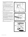
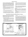
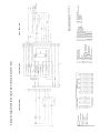
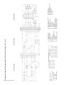
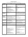
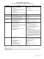
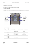
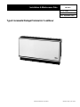
Installation & Maintenance Data
IM 358-6
Group: PTAC
Part No.: 106018431
Date: September 1999
Type K Incremental Packaged Terminal Air Conditioner
©1999 AAF–McQuay Incorporated
IM 358-6 / Page 1 (Rev. 9/99)
Table of Contents
Inspection ........................................................................... 2
Model Nomenclature .......................................................... 3
Wall Opening Requirements .............................................. 3
Wall Box Installation ........................................................... 4
Outdoor Louver Installation ................................................ 5
Heat Section Installation .................................................. 5-7
Sizes 007—014 ............................................................ 5-6
Sizes 019—022 ............................................................... 7
Installation of Heating Only Option .................................... 8
Cooling Chassis Installation ............................................... 8
Electric Power Wiring .................................................... 9-11
Room Cabinet and Control Installation ....................... 11-12
Equipment Start-up ........................................................... 13
Installing Remote Mounted Thermostat ........................... 13
Typical Wiring Diagrams ............................................. 14-28
Standard Chassis, Electric Heat,
MCO Controls, 007—014 .......................................... 14
Standard Chassis, Electric Heat,
MCO Controls, 019—022 .......................................... 15
Standard Chassis, Hot Water Heat,
MCO Controls, 007—014 .......................................... 16
Standard Chassis, Hot Water Heat,
MCO Controls, 019—022 .......................................... 17
Standard Chassis, Steam Heat,
MCO Controls, 007—014 .......................................... 18
Standard Chassis, Steam Heat,
MCO Controls, 019—022 .......................................... 19
Standard Chassis, Electric Heat,
24V, Wallstat, 007—014 ............................................ 2 0
Standard Chassis, Hot Water Heat,
24V, Wallstat, 007—014 ........................................... 21
Standard Chassis, Steam Heat,
24V, Wallstat, 007—014 ........................................... 22
Scheduled Maintenance ................................................... 23
Recommended Spare Parts ............................................. 23
Troubleshooting Chart ................................................. 24-25
Approximate Shipping Weights ........................................ 26
Installation, Service & Warranty Policy ............................ 26
Installation
The installation of this equipment shall be in accordance with the regulations of authorities having jurisdiction and all
applicable codes. It is the responsibility of the installer to determine and follow the applicable codes. Sheet metal parts,
self-tapping screws, clips and such items inherently have sharp edges, and it is necessary that the installer exercise
caution. This equipment is to be installed only by an experienced installation company which employs
trained personnel.
Inspection
When the equipment is received, all items should be carefully
checked against the bill of lading to be sure all crates and
cartons have been received. All units should be carefully inspected for damage when received. If any damage is noticed,
the carrier should make the proper notation on the delivery
receipt acknowledging the damage. The carrier should also
fill out a Carrier Inspection Report. The McQuay Traffic
Department should then be contacted.
The unit nameplate should be checked to make sure the
voltage agrees with the power supply available.
Figure 1.
IM 358-6 / Page 2 (Rev. 9/99)
The Type K Series Comfort Conditioner is designed and
built for through-the-wall installation in either new or existing
buildings. The self-contained refrigerant system delivers cooling to the desired space. Heating can be accomplished with
electric resistance or hydronic heat.
Each conditioner consists of the following components:
● Cooling Chassis
● Room Cabinet
● Heat Section
● Wall Box
● Control
● Louver
TYPE K CHASSIS
P
KES
1
009
C
Z
00
Z
00
AR
14
C
1
B
1
Product Category
P= Type K Incremental
Product Style
1= 1st Tyle Change
Product Identifier
KEC = Type K cool chassis, corrosion protection
KEI = Type K cool chassis, IAQ (positive pressure ventilation)
KES = Type K cool chassis
KHS = Type K heat section
SKU Type
A = Stock
B = Quick Ship
C = Tailored
Color
1 = Antique Ivory
Design Series
1 = A Design
Power Connection
C = Cord
Nominal Capacity
007 = 7,000
009 = 9,000
012 = 12,000
014 = 14,000
019 = 19,000
022 = 22,000
Return Air
14 = Bottom
Discharge
AR = Flat Top
Voltage
A = 115-80-1
C = 208-60-1
J = 265-60-1
P = 208-115-60-1
R = 265-115-60-1
Controls
(None)
Coil Options
(None)
Hand Orientation
Z = Not Applicable
Heating Options
(None)
Wall Opening Requirements
022 as shown below. The wall box is designed to be mounted
on the floor but may be located above the floor line to clear
obstructions. Without cabinet modifications, the wall box can
be placed up to 1'' (25mm) above the floor. The standard
adjustable kickplate can be telescoped to hide the space
below the wall box. Complete wall box installation instructions can found on page 4.
Before installing the unit, check the wall opening to be sure
the wall sleeve will slide in unobstructed. The rough opening
should measure 25'' x 361⁄2'' (635mm x 927mm) indoors and
141/2" x 36 1/2" (368mm x 927mm) outdoors for sizes 007—014
and 273⁄4''x 463⁄4'' (705mm x 1187mm) indoors and 163/8" x
463/4" outdoors (415mm x 1187mm) outdoors for sizes 019—
Figure 2.
Dimensions — inches
Unit Size
007—014
019—022
A
48
60
B
21⁄ 2 Min.
21⁄ 2 Min.
C
71⁄ 4 Min.
81⁄ 2 Min.
D
361 ⁄4
461 ⁄4
E
53 ⁄4
67 ⁄8
F
241 ⁄2
273 ⁄8
G
1311 ⁄16
157 ⁄8
H
21
24
J
31⁄ 2-5 1 ⁄2 Adj.
4-6 Adj.
K
13 ⁄4
3
L
8
91 ⁄4
M
1
5 ⁄8
N
453 ⁄4
591 ⁄2
P
25
273 ⁄4
R
361 ⁄2
463 ⁄4
A
1219
1524
B
64 Min.
64 Min.
C
184 Min.
216 Min.
D
921
1175
E
146
175
F
648
695
G
348
403
H
533
610
J
89-140 Adj.
102-152 Adj.
K
44
76
L
203
235
M
25
16
N
1162
1151
P
635
705
R
927
1187
Dimensions — mm
Unit Size
007—014
019—022
IM 358-6 / Page 3 (Rev. 9/99)
Wall Box Installation
The wall thickness will determine how much, if any, of the wall
box will protrude into the room. Figure 3 shows a typical
installation in a frame and brick wall. These instructions will
vary by depth of wall, but not by wall material. Do not remove
the weather panel at any time during the installation of the
wall box. Premature removal of this panel could result in
improper leveling or sealing. Install the wall box as follows:
1. If the wall opening has not been made, cut and break
through using care to leave interior and exterior surfaces
undamaged. See wall opening requirements on page 3 for
proper size.
2. Install lintels as shown on the plans and specifications.
3. If the wall opening has already been made, measure it to
be certain it has adequate clearance for the wall box. Be
sure to allow extra clearance for insulation around the wall
box to reduce sound and heat transfer. Continue with step
#4.
5. Place 2'' (51mm) fiberglass batt or 1" (25mm) styrofoam
insulation around the top and sides of the wall box.
6. Locate the wall box in the wall opening with the weather
panel to the outside. Use the top edge of the wall box for
horizontal leveling. The wall box must also be vertically
plumb. Shim the wall box to accomplish this. Recess so
louver is flush with outside wall.
7. Drill four (4) holes in the sides of the wall box and attach it
to the walls securely using appropriate fasteners.
Note: Never drill through bottom of wall box.
8. If face brick is being installed, continue coursing up the wall
until the wall box is completely surrounded and becomes
an integral part of the wall.
9. Caulk interior and exterior perimeter weathertight where
the box meets the wall. Use a nonhardening, waterproof
caulk such as silicone.
4. Apply a layer of mortar or roofing cement to the bottom
surface of the opening (see Figure 3).
Note: For rooms with thick carpet, wall box should be installed
1
⁄2'' (13mm) above concrete floor to facilitate future chassis
installation and removal.
Figure 3. (Drawing Not To Scale)
Table 1.
Dimension “A”
in.
0 to -1
0 to +1
1 to 2
2 to 3
3 to 4
4 to 5
5 to 6
6 to 7
7 to 8
8 to 9
mm
0 to -25
0 to +25
25 to 51
51 to 76
76 to 102
102 to 127
127 to 152
152 to 178
178 to 203
203 to 229
Hydronic
007—014
in.
mm
81 ⁄4
210
91 ⁄4
235
101⁄ 4
260
111⁄ 4
286
121⁄ 4
311
131⁄ 4
327
141⁄ 4
362
151⁄ 4
387
161⁄ 4
413
171⁄ 4
438
Heat
019—022
in.
mm
81 ⁄2
216
91 ⁄2
241
101⁄ 2
267
111⁄ 2
292
121⁄ 2
318
131⁄ 2
343
141⁄ 2
368
151⁄ 2
394
161⁄ 2
419
Note: Dimension “B” will vary by the thickness of the wall, the type of louver,
the amount the louver is recessed into the wall (if any) and the amount the wall
sleeve extends into the room. The minimum “B” dimension is 21 ⁄ 2'' (64mm). The
wall box can be factory furnished in increments between 21 ⁄ 2'' (64mm) and 10''
(254mm). Wall sleeve extensions in 1'' (25mm) increments can also be
provided to attach to the rear of the wall sleeve.
12345678901234
1234567890123456
1234567890123456
12345678901234
1234567890123456
1234567890123456
12345678901234
1234567890123456
1234567890123456
123456789012345
12345678901234
1234567890123456
12345678901234
123456789012345
1234567890123456
12345678901234
123456789012345
1234567890123456
Caulk Around
Opening
Before
Installing
Louver
Table 2.
Dimensions — inches
Wall Box
“B” Dimension
Overall Length
Dimensions — mm
Wall Box
“B” Dimension
Overall Length
IM 358-6 / Page 4 (Rev. 9/99)
007— 014
019 — 022
007— 014
019— 022
21⁄ 2
21⁄ 2
101 ⁄2
113 ⁄4
31⁄ 2
31⁄ 2
111 ⁄2
123 ⁄4
4
41 ⁄2
12
133 ⁄4
5
51 ⁄2
13
143 ⁄4
6
61 ⁄2
14
153 ⁄4
7
71 ⁄2
15
163 ⁄4
8
81 ⁄2
16
173 ⁄4
9
91 ⁄2
17
183 ⁄4
10
101 ⁄2
18
193 ⁄4
007— 014
019 — 022
007— 014
019— 022
64
64
267
298
89
89
292
324
102
114
305
349
127
140
330
375
152
165
356
400
178
191
381
425
203
216
406
451
229
241
432
476
254
267
457
502
Outdoor Louver Installation
1. Remove the louver from the shipping carton which also
contains the mounting hardware.
wall box and pull it back so the louver studs pass through
the holes of the wall box flange (see Figure 4).
2. Remove the weather panel from the wall sleeve to gain
access to the outside of the wall box. Verify that gap
between exterior wall and wall box is caulked.
6. Attach the washers and nuts to secure the louver in place.
3. If an optional louver frame is required, install prior to louver
installation. Caulk that portion of the frame which will come
in contact with the wall. Pass the louver frame through the
wall box opening and from the outside of the building, slide
over the end of the wall box. Position as desired, then drill
holes through the top and sides of the overlapping wall box
and louver frame. Secure to the wall with screws. Caulk
wall box/louver frame joint on all four sides. Provide
additional caulking around outside wall and louver frame
to ensure a weather tight seal.
7. If heat section and cool chassis are not to be immediately
installed, replace the weather panel.
Figure 4.
4. Make a temporary handle by looping a piece of flexible
wire or heavy cord through the louver. This will insure that
a firm grasp can be maintained during installation.
5. From a position inside the room, push the louver through
the opening at the rear of the wall box. Line it up with the
Heat Section Installation (Sizes 007– 014)
The Type K heat section is matched to the Type K cooling
chassis but packaged and shipped separately. Check the
heat section carton label and the unit’s nameplate to ensure
it is correct for the cooling chassis and the space.
The following steps should be followed when installing the
heat section:
1. Remove the heater from the shipping carton and examine
for concealed damage. Report any damage found to the
carrier. The control is packaged with the heat section
in a separate carton. Remove this carton from the heat
section and set it aside until after the heat section is
installed.
2. Manually spin the blowers to make sure there is no interference. Minor misalignment may have occurred during
shipping and should be corrected. If it can’t be corrected
with minor adjustment, the condition should be reported to
the factory. Do not lubricate roomside motor at this time.
Each unit is adequately lubricated before leaving the
factory.
3. Observe the method of installation. The heat section has
side channels that ride on rails in the wall box. At the back
of the wall box towards the top are two hooks that engage
the heat section. Locate these hooks before sliding the
heat section in place. “U”-shaped clips are included that
lock the heat section in place once installed. “U”-clips can
usually be found taped to the wall box interior.
4. Remove the weather panel from the wall box. If the louver
has not been installed, install it before placing the heat
section into the wall box.
5. Slide the heat section into place so that the holes of the
heat section surround the hooks of the wall box. Lock it to
the wall box using the “U”-shaped clips provided (see
Figure 5). The “U”-shaped clips should be positioned with
the open end pointing down.
Figure 5.
IM 358-6 / Page 5 (Rev. 9/99)
Additional Instructions for Hydronic Heat (Sizes 007– 014)
type of system and the pressure applied.
When hot water is used, an air vent must be installed
at the highest point in the piping connection. If the vent is
not automatic, it should be piped with easy access for
regular maintenance. Caution: Locate vent so it does
not drip or spray on electrical components.
6. The piping for steam or hot water can be supplied from
either the right or left side of the coil. Hot water must be
supplied to the bottom of the coil, and steam to the top of
the coil. See Detail A through H for specifics. To simplify
connections to the coil, use 5⁄8'' O.D. copper tubing where
local codes allow.
9. Insulate all exposed water or steam lines that are located
within the room cabinet. Failure to do this may cause
erratic operation of the thermostat.
7. A shutoff valve is recommended on the supply and return
side of the coil.
10. Protect the heat section from damage during construction. Do not operate the heat section without a filter or
the warranty will be void.
8. When steam is used, a trap is required on the return side.
Trap size should be determined by the consulting
engineer or steam trap supplier, depending upon the
Figure 6. Suggested Piping Arrangements
Hot Water Supply
Steam Supply
Detail "A" – Hot Water Supply R.H., Return L.H.
Detail "B" – Steam Supply R.H., Return L.H.
2"
(51mm)
Return Stub
CL
CL
C
L
25/8 "
(67mm)
Return Stub
W
Y
S
T
25/8 "
(67mm)
V
S
T
Detail "D" – Steam Supply R.H., Return R.H.
Detail "C" – Hot Water Supply R.H., Return R.H.
C
L
C
L
U
Return
Stub
2"
(51mm)
V
C
L
C
L
2"
(51mm)
U
1"
(25mm)
Return Stub
W
T
Y
1"
(25mm)
V
T
Detail "F" – Steam Supply L.H., Return R.H.
Detail "E" – Hot Water Supply L.H., Return R.H.
C
L
2"
(51mm)
Return Stub
2"
(51mm)
V
25 /8"
(67mm)
C
L
C
L
Return Stub
C
L
W
25 /8"
(67mm)
S
V
Y
2"
(51mm)
U
C
L
C
L
Return Stub
1"
(25mm)
S
C
L
C
L
Y
2"
(51mm)
U
V
IN.
MM
IM 358-6 / Page 6 (Rev. 9/99)
S
Return Stub
W
1"
(25mm)
U
Detail "H" – Steam Supply L.H., Return L.H.
Detail "G" – Hot Water Supply L.H., Return L.H.
2"
(51mm)
S
V
S
191 ⁄4
489
T
213 ⁄4
552
U
211 ⁄4
540
V
101 ⁄2
267
W
231 ⁄2
597
V
Y
201 ⁄4
514
U
Heat Section Installation (Sizes 019 – 022)
Figure 7 shows the heat section installed in a standard wall
box. Note that the heat section slides into a wall box on the
slide rails. For heat section installation, proceed as follows:
Figure 7.
1. Remove heat section from shipping carton.
2. Visually check for shipping damage and report any visible
damage immediately to the trucker. Spin blower wheels by
hand to assure they do not rub within their housing.
Shipping may have loosened mounts. Adjust as required.
3. Check voltage rating on dataplate fastened to heat
section. This must conform to voltage supplied for the
equipment.
4. Locate slide rails on each side of wall box and insert heater
section into the wall box. Slide to the rear until it is firmly
seated.
5. Screw in the heat section lock screws as shown in Figure
7. (Screws are shipped with the heat section.)
Steam or Hot Water Application (Sizes 019 – 022)
When the heat section requires steam or hot water, the
installation varies. See Figures 9 and 10 for suggested piping
arrangements.
Figure 9. Hot Water Coil
1. Supply and return piping for steam or hot water is supplied
from right-hand side only. Hot water must be supplied to
the bottom of the coil, and steam to the top of the coil.
2. To simplify the steam or hot water connections to the coil,
use 5⁄8'' O.D. copper tubing where local codes permit. See
Figure 8 for rough-in dimensions.
3. When hot water is to be used, an air vent must be put in at
the highest point in the piping connection. See Figure 9. If
the air vent used is not of the automatic type, it should be
piped so that it may be easily opened.
4. A shutoff valve is recommended on the supply and return
side of the coil. A steam trap is required on the return side
when steam is used for heating. See Figure 10.
5. All steam or hot water lines which are located within the
room cabinet should be insulated.
Warning: If the heat section is used for heating an area
during construction, specifically plastering, precautions must
be taken to protect the equipment by using covers of corrugated board, sheet metal or plywood. If the installation
specifies heat only, be sure to install permanent weather
panel and filter adapter (see “Installation of Heating Only
Option”). Failure to heed this warning can cause malfunction
of the equipment.
Figure 10. Steam Coil
Figure 8.
IM 358-6 / Page 7 (Rev. 9/99)
Cooling Chassis Installation
1. Remove the cooling chassis from the shipping carton and
examine it for damage. Do not rest it on end. Check the
plate rating against the power supply to make sure that
they are the same (see Figure 12). Also check the size (capacity) to make sure that it coincides with the heat section;
e.g., Size 009 cooling.
2. The cooling chassis is supplied with an internal spring
mounted compressor. The hold-down nuts on the compressor mountings should not be loosened.
3. Manually spin the condenser fan wheel to be sure that
there is no interference or looseness. If it is loose, tighten
the setscrew located over the center of the flat on the motor
Figure 12.
IM 358-6 / Page 8 (Rev. 9/99)
shaft. Do not lubricate condenser fan motor at time of
installation.
4. Slide the chassis into the wall box. Chassis must be
square in the box so that all the rubber seals are pressed
tight. Check bottom seal between chassis and wall box to
ensure that it has not been unseated from slot during
chassis installation.
5. For unit sizes 019—022, there is a “J” bolt on each side
that holds the chassis in place. Thread the “J” bolts
through the holes supplied in the chassis and tighten until
the chassis is firmly seated in the wall box.
Electric Power Wiring
Before making any electrical connections, observe the
following precautions:
a. By installing a remote double-pole switch in the
conditioner’s power line within sight of the unit.
1. Check the nameplate rating of the heat section and cooling chassis to make sure the equipment is connected to
the proper power supply and that proper fusing is used.
b. By installing a double pole, single throw “on-off”
switch located in a convenient position within the room
cabinet.
2. In cases where a number of conditioners are to
be installed, single circuits should be provided for
each machine.
After all these precautions are observed, proceed as follows:
3. A separate disconnect is recommended for each
conditioner in addition to individual fusing. This can be
accomplished in several ways:
Units With Electric Heat (Sizes 007–022)
A 4" x 4" electrical junction box is located on the left side of the
heat section. Field wiring should be brought to this point for
power to the unit. See Figure 13 & 14.
Figure 13. Electric Heat Section (Sizes 007–014)
Notes:
➀ Guest room control, low voltage or master/slave wiring connections made at control box.
➁ 4'' x 24'' (102mm x 51m) wall space for electrical conduits except behind junction box.
➂ Junction box with knockout for 1/2'' (12mm) and 3/4'' (19mm) conduit.
4
Refer to page 4 for “B” dimension.
Figure 14. Electric Heat Section (Sizes 019–022)
Notes:
➀ Guest room control, low voltage or master/slave wiring connections made at control box.
➁ Refer to page 4 for “B” dimension.
IM 358-6 / Page 9 (Rev. 9/99)
Units With Hydronic Heat (Sizes 007–014)
The hydronic heat section can be supplied with a short (41⁄4''
high) control box or a long (13 1⁄ 2'' high) control box depending
on the number of options selected. Observe the control box
to determine which one was supplied for the job.
Small Control Box — If the short control box was supplied,
field wiring should be brought into the 2'' x 4'' junction box
which is located on the right-hand side of the heat section (see
Figure 15.)
Long Control Box
1. If the long control box was provided, make electrical
connections to a field supplied junction box that should be
fastened to the floor beneath the control (see Figure 16).
2. Locate the long control box. The power wires for the
control extend through the piece of flexible conduit that
exits from the bottom of the control. These wires should be
connected to the incoming power at the junction box
installed in Step 1.
Remote Control — For units with remote mounted
thermostat, refer to page 13.
Figure 15. Hydronic Heat Section With Short Control Box (Sizes 007–014)
Notes:
➀ See Detail A, B, C, D, E, F, G, or H on page 6 for dimensions of factory installed valve and return piping stub; 5/ 8'' O.D. copper tubing.
➁ Junction box has 7 /8'' diameter knockouts for 1/ 2'' conduit.
➂ Refer to page 4 for “B” dimension.
Figure 16. Hydronic Heat Section With Long Control Box (Sizes 007–014)
Notes:
➀ See Detail G or H on page 6 for dimensions of factory installed valve and return piping stub; 5 /8'' O.D. copper tubing.
➁ Refer to page 4 for “B” dimension..
IM 358-6 / Page 10 (Rev. 9/99)
Unit with Hydronic Heat (sizes 019–022)
1. Only one size control box is available for sizes 019–022.
Make all electrical connections to a factory supplied
junction box located on the L.H. side of the wall box.
(see Figure 17).
Figure 17. Hydronic Units (Sizes 019–022)
Coil Stubs for
Field Piping
Control Box
Room Cabinet
Control
Box
Main Power Cord
B
1
Heat Chassis
Power Cord
Cool
Chassis
Power
Cord
Room
Cabinet
Mounting
Holes (4)
Wall Box
(End View
w/o Cabinet)
Heat Chassis
Power Cord
Cool Chassis
Power Cord
Side View
Front View
4" x 4" Junction Box
(Mounted by Others)
Field Mounted to L.H. Edge of Wall Box
1
Refer to page 4 for "B" dimension.
Room Cabinet and Control Installation
The depth of the room cabinet varies by the amount the wall
box extends into the room. Check the unit tagging against the
room cabinet tagging to be sure they match. Installation of the
control box should be done at the same time as the room
cabinet.
Figure 18.
1. Remove the cabinet from the carton and inspect it for
damage. If any is found, contact the carrier immediately.
The room cabinet is made up of six pieces: a cabinet, a
removable front panel, a discharge grille, two (2) end
plates, and a kickplate. Make sure all pieces are included
with the room cabinet.
Remove the front panel by unlocking the concealed
latches at the bottom corners of the front panel (see Figure
18). Once latches are released, lift the front panel slightly
and pull panel forward, then lift again and remove from the
surrounding cabinet. Unit sizes 019—022 utilize safety
chains that must be disconnected from the room cabinet in
order to remove the front panel.
2. For unit sizes 007–014: Place the cabinet around the
installed wall box, heat section and cool chassis and push
the cabinet firmly against the wall. The discharge grille
seals should rest on the discharge opening of the
heat section.
Figure 19.
For unit sizes 019–022: Position the room cabinet over
the heat section so that the two studs on each side are
positioned over the matching slots in the heat section. Set
the cabinet down on the heat section, push tight against
the wall and secure using wing nuts supplied. See Figure 19.
3. Fasten the cabinet to the wall using appropriate fasteners.
The back flanges of the room cabinet have factory
furnished holes for securing the cabinet to the wall.
IM 358-6 / Page 11 (Rev. 9/99)
4. Fasten the two (2) end plates to the room cabinet using
the wing nuts supplied. These end plates are adjustable
and should be positioned to set flat on the finished floor
(see Figure 20).
Figure 20.
5. Locate the kickplate and clip it into the slots provided in
the end plates so that the flange is toward the floor.
6. Take the control box and escutcheon plate out of the
carton for attachment to the room cabinet.
7. There are two flanges beneath the control door that
support the control box (see Figure 21). Remove the two
screws in the control box that hold the escutcheon plate
in place. Remove the thermostat knob and escutcheon
plate.
8. While holding the control box in position, set the
escutcheon plate in place on the flanges beneath the
control door.
9. Using the two screws removed in Step 7, secure the
control box and escutcheon plate to the room cabinet.
10. Replace the thermostat control knob.
11. Connect the power cord from the heat section to the
bottom of the control box. Plug in the cord from the
control box to the receptacle in the cooling chassis.
Figure 21.
12. Move the thermostat bulb to the cooling chassis and
secure it to the snap clips provided. Inspect the filter to be
sure it is securely in place.
13. Loosen the wing nuts on the nose piece that is attached
to the heat section. Slide the nose piece toward the room
cabinet until it makes contact. Tighten wing nuts to
secure the nose piece in place. This nose piece prevents
air from leaking back into the cabinet and giving the
thermostat a false reading.
14. Retrieve the front panel and replace it in the room cabinet. Lock the concealed latches in place to prevent unauthorized tampering (see Figure 22). Note: Latches
must be in the open position before installing the front
panel.
15. Wipe cabinet with a soft cloth to remove smudges. If
required, use a mild, nonabrasive cleanser.
IM 358-6 / Page 12 (Rev. 9/99)
Figure 22.
Equipment Start-up
Initial start-up of the McQuay equipment by an experienced
person is usually the responsibility of the installing contractor.
This consists of inspecting and operating the equipment for all
functions at the time of initial installation, and making
adjustments as necessary. It also includes demonstrating its
proper operation to the owners or their agents. Note that
unless otherwise specifically agreed to in writing, there is no
field labor or start-up service included in the price of
the equipment.
The Type K unit is furnished with a concealed fan cycle
rocker switch on the control box. Before start-up, open the
front panel and place this switch in the “cycle” position.
Continue start-up procedures as follows:
1. Check the main power supply to be sure there is power to
the unit.
2. Open the control access door and press the button labeled
F-Fan. The indoor fans should be energized.
3. Move the fan speed rocker switch from “Low Fan” to “High
Fan” and back again. The fan speed should change.
4. Depress the button marked H-Heat. Turn the thermostat
knob completely counterclockwise. The electric heat
elements or the hydronic valve should become energized
and noticeable heat should be felt at the discharge grille.
5. Depress the C-Cool button and move the thermostat
completely clockwise. The compressor and condenser fan
should come on and the air from the discharge should feel
cold.
6. Depress the S-Stop button and all functions of the unit
should stop. Caution: The stop button does not disconnect
power to the unit. Before servicing the equipment, disconnect the unit from the power source.
Ventilation
The introduction of outside air is controlled by an automatic
damper. During normal operation, the damper will be open
whenever the Heat, Cool, or Fan control buttons are
depressed. If the indoor fan is not energized, the damper will
be closed.
A concealed cutoff switch is provided so that the damper
can be kept closed.
This switch is located at the front left-hand side of the
cooling chassis (see Figure 12). It can be reached by removing the front panel.
Remote Mounted Thermostat Installation (Sizes 007—014 Only)
Units that are furnished with remote mounted thermostats
should be wired as shown in Figure 23. The connections for
field wiring are on a seven-position terminal board located on
the face of the control box. Other considerations for remote
mounted thermostat are as follows:
1. If slave units are to be employed, remove the jumper from
terminals A to C of the slave unit. Connect terminal A of the
master unit to the corresponding terminal A of the slave
unit as shown in Figure 23.
The master unit is furnished with a 50 VA transformer
that is capable of handling up to 7 slave units. If additional
slave units are to be added, a larger field supplied transformer must be mounted external to the unit. The master
and slave units draw 5.6 VA each. Furnish a transformer
to handle the number of slaves installed, plus the
master unit.
2. When using a programmable wall thermostat, connect the
common terminal of the thermostat to terminal A of the unit
terminal board. Refer to the instructions furnished with the
thermostat to locate the common terminal. Note: It may be
necessary to reduce the number of slave units connected
to the master or field supply a larger transformer when
using a programmable thermostat. Check the VA draw of
the chosen thermostat, plus the VA draw of the master and
slave units to be sure the total doesn’t exceed 50 VA power
draw. Slave units are connected as described in #1 above.
Figure 23.
Manual Changeover Thermostat
Automatic Changeover Thermostat
Thermostat Part # 0046736101
Subbase Part # 0046742100
Thermostat Part #0060685101
Subbase Part # 0002005963
(Add in
Field)
Y1 W1
Y1 W1
IM 358-6 / Page 13 (Rev. 9/99)
IM 358-6 / Page 14 (Rev. 9/99)
COOL SECTION
R1
R2
R3
C1
C2
C3
GRC
HL
HTR
MP
NSP
P1
CONTROL BOX
Capacitor, Indoor Fan
Capacitor, Outdoor Fan
Capacitor, Compressor
Guest Room Control
High Limit
Heater
Motor Protector
Night Setback Control
Plug, Control Box/Heat Section
to Cool Section
Relay, Heat
Relay, Cool
Relay, Night Setback (NSB)
Typical Wiring Diagrams
Standard Chassis With Electric Heat & MCO Controls (Sizes 007—014)
R4
R5
R6
R7
S1
S2
S3
S4
T1
TB1
TB2
TB3
TB4
Relay, Guest Room Control (GRC)
Relay, Hot Water Valve
Relay, Control
Relay, Night Setback (NSB)
Control Switch
Fan Speed Switch
Fan Cycle Switch
Damper Switch
Transformer
Terminal Block, Control Box
Terminal Board (24V), Control Box
Terminal Board, Heat Section
Terminal Board, Cool Section
TB6
TC1
TC2
TC3
TC4
VM
WN
HEAT SECTION
Terminal Box
Room Thermostat
Night Setback Thermostat (NSB)
Heat Fan Lockout
Low Ambient Lockout
Valve Motor
Wire Nut
IM 358-6 / Page 15 (Rev. 9/99)
COOL SECTION
CONTROL BOX
C1
C2
C3
F1
HL
HTR
MP
P1
P2
P3
P4
P5
R1
R2
Standard Chassis With Electric Heat & MCO Controls (Sizes 019—022)
Capacitor, Indoor Fan
Capacitor, Outdoor Fan
Capacitor, Compressor
Fuse
High Limit
Heater
Motor Protector
Plug, Heat Section to Cool Section
Plug, Heat Section to Control Box
Plug, PC Board
Plug, on Master Wire Harness
Plug, on Master Wire Harness
Relay, Run
Relay, Outdoor Fan Motor
R3
R4
R5
R6
R7
R9
S1
S4
T1
TB2
TB3
TB4
TB5
TB6
Relay, Cooling
Relay, Indoor Fan Motor
Relay Heating 1st Stage
Relay, Heating 2nd Stage
Relay, Night Setback (NSB)
Relay, Hot Water Valve
Control Switch
Damper Switch
Transformer
Terminal Box
Terminal Box
Terminal Box
Terminal Box
Terminal Box
TC1
TC2
TC5
VM
WN
Room Thermostat
Night Setback Thermostat (NSB)
Freezestat
Valve Motor
Wire Nut
Note: Large heat shown. Refer to unit diagram for
details of small or medium heat.
HEAT SECTION
IM 358-6 / Page 16 (Rev. 9/99)
COOL SECTION
R1
R2
R3
C1
C2
C3
GRC
HL
HTR
MP
NSP
P1
Capacitor, Indoor Fan
Capacitor, Outdoor Fan
Capacitor, Compressor
Guest Room Control
High Limit
Heater
Motor Protector
Night Setback Control
Plug, Control Box/Heat Section
to Cool Section
Relay, Heat
Relay, Cool
Relay, Night Setback (NSB)
HEAT SECTION
Standard Chassis With Hot Water Heat & MCO Controls (Sizes 007—014)
R4
R5
R6
R7
S1
S2
S3
S4
T1
TB1
TB2
TB3
TB4
Relay, Guest Room Control (GRC)
Relay, Hot Water Valve
Relay, Control
Relay, Night Setback (NSB)
Control Switch
Fan Speed Switch
Fan Cycle Switch
Damper Switch
Transformer
Terminal Block, Control Box
Terminal Board (24V), Control Box
Terminal Board, Heat Section
Terminal Board, Cool Section
TB6
TC1
TC2
TC3
TC4
VM
WN
Terminal Box
Room Thermostat
Night Setback Thermostat (NSB)
Heat Fan Lockout
Low Ambient Lockout
Valve Motor
Wire Nut
CONTROL BOX
IM 358-6 / Page 17 (Rev. 9/99)
COOL SECTION
C1
C2
C3
F1
HL
HTR
MP
P1
P2
P3
P4
P5
R1
R2
CONTROL BOX
Standard Chassis With Hot Water & MCO Controls (Sizes 019—022)
Capacitor, Indoor Fan
Capacitor, Outdoor Fan
Capacitor, Compressor
Fuse
High Limit
Heater
Motor Protector
Plug, Heat Section to Cool Section
Plug, Heat Section to Control Box
Plug, PC Board
Plug, on Master Wire Harness
Plug, on Master Wire Harness
Relay, Run
Relay, Outdoor Fan Motor
R3
R4
R5
R6
R7
R9
S1
S4
T1
TB2
TB3
TB4
TB5
TB6
Relay, Cooling
Relay, Indoor Fan Motor
Relay Heating 1st Stage
Relay, Heating 2nd Stage
Relay, Night Setback (NSB)
Relay, Hot Water Valve
Control Switch
Damper Switch
Transformer
Terminal Box
Terminal Box
Terminal Box
Terminal Box
Terminal Box
TC1
TC2
TC5
VM
WN
HEAT SECTION
Room Thermostat
Night Setback Thermostat (NSB)
Freezestat
Valve Motor
Wire Nut
IM 358-6 / Page 18 (Rev. 9/99)
COOL SECTION
R1
R2
R3
C1
C2
C3
GRC
HL
HTR
MP
NSP
P1
Capacitor, Indoor Fan
Capacitor, Outdoor Fan
Capacitor, Compressor
Guest Room Control
High Limit
Heater
Motor Protector
Night Setback Control
Plug, Control Box/Heat Section
to Cool Section
Relay, Heat
Relay, Cool
Relay, Night Setback (NSB)
HEAT SECTION
Standard Chassis With Steam Heat & MCO Controls (Sizes 007—014)
R4
R5
R6
R7
S1
S2
S3
S4
T1
TB1
TB2
TB3
TB4
Relay, Guest Room Control (GRC)
Relay, Hot Water Valve
Relay, Control
Relay, Night Setback (NSB)
Control Switch
Fan Speed Switch
Fan Cycle Switch
Damper Switch
Transformer
Terminal Block, Control Box
Terminal Board (24V), Control Box
Terminal Board, Heat Section
Terminal Board, Cool Section
TB6
TC1
TC2
TC3
TC4
VM
WN
CONTROL BOX
Terminal Box
Room Thermostat
Night Setback Thermostat (NSB)
Heat Fan Lockout
Low Ambient Lockout
Valve Motor
Wire Nut
IM 358-6 / Page 19 (Rev. 9/99)
COOL SECTION
C1
C2
C3
F1
HL
HTR
MP
P1
P2
P3
P4
P5
R1
R2
CONTROL BOX
Standard Chassis With Steam Heat & MCO Controls (Sizes 019—022)
Capacitor, Indoor Fan
Capacitor, Outdoor Fan
Capacitor, Compressor
Fuse
High Limit
Heater
Motor Protector
Plug, Heat Section to Cool Section
Plug, Heat Section to Control Box
Plug, PC Board
Plug, on Master Wire Harness
Plug, on Master Wire Harness
Relay, Run
Relay, Outdoor Fan Motor
R3
R4
R5
R6
R7
R9
S1
S4
T1
TB2
TB3
TB4
TB5
TB6
Relay, Cooling
Relay, Indoor Fan Motor
Relay Heating 1st Stage
Relay, Heating 2nd Stage
Relay, Night Setback (NSB)
Relay, Hot Water Valve
Control Switch
Damper Switch
Transformer
Terminal Box
Terminal Box
Terminal Box
Terminal Box
Terminal Box
TC1
TC2
TC5
VM
WN
HEAT SECTION
Room Thermostat
Night Setback Thermostat (NSB)
Freezestat
Valve Motor
Wire Nut
IM 358-6 / Page 20 (Rev. 9/99)
COOL SECTION
R1
R2
R3
C1
C2
C3
GRC
HL
HTR
MP
NSP
P1
CONTROL BOX
Capacitor, Indoor Fan
Capacitor, Outdoor Fan
Capacitor, Compressor
Guest Room Control
High Limit
Heater
Motor Protector
Night Setback Control
Plug, Control Box/Heat Section
to Cool Section
Relay, Heat
Relay, Cool
Relay, Night Setback (NSB)
Standard Chassis With Electric Heat & 24V Wall Stat (Sizes 007—014)
R4
R5
R6
R7
S1
S2
S3
S4
T1
TB1
TB2
TB3
TB4
Relay, Guest Room Control (GRC)
Relay, Hot Water Valve
Relay, Control
Relay, Night Setback (NSB)
Control Switch
Fan Speed Switch
Fan Cycle Switch
Damper Switch
Transformer
Terminal Block, Control Box
Terminal Board (24V), Control Box
Terminal Board, Heat Section
Terminal Board, Cool Section
TB6
TC1
TC2
TC3
TC4
VM
WN
HEAT SECTION
Terminal Box
Room Thermostat
Night Setback Thermostat (NSB)
Heat Fan Lockout
Low Ambient Lockout
Valve Motor
Wire Nut
IM 358-6 / Page 21 (Rev. 9/99)
COOL SECTION
R1
R2
R3
C1
C2
C3
GRC
HL
HTR
MP
NSP
P1
CONTROL BOX
Capacitor, Indoor Fan
Capacitor, Outdoor Fan
Capacitor, Compressor
Guest Room Control
High Limit
Heater
Motor Protector
Night Setback Control
Plug, Control Box/Heat Section
to Cool Section
Relay, Heat
Relay, Cool
Relay, Night Setback (NSB)
Standard Chassis With Hot Water Heat & 24V Wall Stat (Sizes 007—014)
R4
R5
R6
R7
S1
S2
S3
S4
T1
TB1
TB2
TB3
TB4
Relay, Guest Room Control (GRC)
Relay, Hot Water Valve
Relay, Control
Relay, Night Setback (NSB)
Control Switch
Fan Speed Switch
Fan Cycle Switch
Damper Switch
Transformer
Terminal Block, Control Box
Terminal Board (24V), Control Box
Terminal Board, Heat Section
Terminal Board, Cool Section
TB6
TC1
TC2
TC3
TC4
VM
WN
HEAT SECTION
Terminal Box
Room Thermostat
Night Setback Thermostat (NSB)
Heat Fan Lockout
Low Ambient Lockout
Valve Motor
Wire Nut
IM 358-6 / Page 22 (Rev. 9/99)
COOL SECTION
R1
R2
R3
C1
C2
C3
GRC
HL
HTR
MP
NSP
P1
CONTROL BOX
Standard Chassis With Steam Heat & 24V Wall Stat (Sizes 007—014)
Capacitor, Indoor Fan
Capacitor, Outdoor Fan
Capacitor, Compressor
Guest Room Control
High Limit
Heater
Motor Protector
Night Setback Control
Plug, Control Box/Heat Section
to Cool Section
Relay, Heat
Relay, Cool
Relay, Night Setback (NSB)
R4
R5
R6
R7
S1
S2
S3
S4
T1
TB1
TB2
TB3
TB4
Relay, Guest Room Control (GRC)
Relay, Hot Water Valve
Relay, Control
Relay, Night Setback (NSB)
Control Switch
Fan Speed Switch
Fan Cycle Switch
Damper Switch
Transformer
Terminal Block, Control Box
Terminal Board (24V), Control Box
Terminal Board, Heat Section
Terminal Board, Cool Section
TB6
TC1
TC2
TC3
TC4
VM
WN
HEAT SECTION
Terminal Box
Room Thermostat
Night Setback Thermostat (NSB)
Heat Fan Lockout
Low Ambient Lockout
Valve Motor
Wire Nut
Scheduled Maintenance
Incremental conditioners are built to last. With proper care,
the unit should provide uninterrupted service for many years.
Scheduled maintenance of this equipment, as described
below, is the key to the equipment’s longevity.
Air filters must be cleaned at regular intervals. Twice
annually may be adequate in some areas while twice monthly
may be required in others. Areas with high dirt and lint
content or heavy usage of units require more frequent filter
maintenance that those areas of relatively clean operating or
low usage conditions. Unit malfunction may occur if air filters
are not kept clean.
The standard filter supplied with the Type K unit is a
permanent wire mesh type. This type of filter should be rinsed
with hot water and a mild detergent. Let dry and oil lightly to
enhance dust collecting ability.
The Type K is also available with a carbon filter, a zeolite
filter or electrostatic filter. The electrostatic filter is renewable
by rinsing with hot water and replacing in the unit once dry.
The carbon or zeolite filters must be discarded and replaced.
The frequency of this replacement depends on the air quality
of the room being filtered. Rooms with heavy smoke or
ammonia content will require more frequent filter changes
than rooms with minimal degrees of smoke or ammonia.
Note: When replacing the standard filter with an optional
carbon, electrostatic, or zeolite filter, compress the filter
brackets slightly. The optional filters are slightly thinner than
the standard filter and will stay in place better if the brackets
are squeezed slightly.
It is recommended that the chassis be removed every year
for a thorough check-up. The heat section need not be
removed but should be inspected or cleaned if necessary.
Should the heat section blowers or motor need service, the
entire fan board can be easily removed from the unit for
service.
To access the unit for cleaning or service, proceed as
follows:
1. Disconnect power to the unit.
2. Remove the front panel and the kickplate.
3. Unplug the chassis from the control box and remove the
chassis from the wall sleeve. Replace with spare chassis
or weatherplate.
4. Move chassis to maintenance area and check all seals,
wires, and insulation and repair as required.
5. Cover motor and protect all electrical components before
washing dirt from chassis.
Warning: Residential and institutional cleaning
compounds can cause permanent damage to the
packaged terminal unit. To avoid damage to unit controls
and heat transfer surfaces, do not spray cleaning
compounds onto the return air opening or unit controls.
Normal cleaning can be accomplished by wiping the unit
surface with a damp cloth. When using cleaning
compounds on carpets, floors or walls, turn the unit off to
avoid drawing potentially damaging vapors into the
package terminal unit.
6. Clean condensate drain and clear weep holes.
7. Dry equipment thoroughly, especially electric parts and
insulation.
8. Clean any rust spots with steel wool and paint with rust
inhibiting paint.
9. Check all fasteners and tighten if necessary.
10. Check the motor nameplate for routine oiling
instructions.
11. Test run chassis before reinstalling or returning to spare
parts stock.
Recommended Spare Parts
An advantage of the Incremental system is that failure of any
one part affects only one Incremental conditioner and does
not interrupt the operation of the rest of the system. A further
advantage is that a failed part can be quickly and easily
replaced, thus minimizing the inoperative time of the
equipment. This is so, however, only if a replacement part is
quickly available. In order to replace a failed part quickly and
keep all Incremental conditioners in good operating
condition, McQuay International recommends that at the time
Incremental conditioners are purchased, owners arrange for
a small stock of replacement parts.
Where an owner carries such a stock, immediate replacement of a defective part is possible. The defective part can
then be returned to McQuay International or one of its
authorized service stations. So long as it is still in warranty, it
is repaired or replaced and returned to the owner without cost
for shop labor and material. Thus, the stock of replacement
parts is constantly replenished. To the right is listed the kind
of parts which McQuay International recommends be carried
in stock, together with the quantity of parts recommended per
100 Incremental conditioners installed.
Qty. Per
Part Name
100 Units
Cooling Chassis ........................................................ 1
Compressor Overload Device .................................. 1
Compressor Running Capacity ................................ 1
Indoor Fan Motor ...................................................... 1
Outdoor Fan Motor ................................................... 1
Outdoor Fan Motor Capacitor ................................... 1
Pushbutton Switch .................................................... 2
Damper Switch ......................................................... 2
Thermostat ................................................................ 2
Knob for Thermostat ................................................. 6
Control Relay ............................................................ 2
Damper Motor ........................................................... 2
Hydronic Valve .......................................................... 4
Spare Filter ............................................................... 10
Touch-up Paint (1 Pt. Spray Can) ............................ 1
For the current spare parts list, and applicable prices, see our
McQuay representative or write McQuayService, P.O Box
1551, Minneapolis, MN 55440.
IM 358-6 / Page 23 (Rev. 9/99)
Troubleshooting Chart
These items should be checked by a qualified service technician only.
TROUBLE
1. Blowers won't
operate on Cool.
CAUSE
CURE
b. Faulty pushbutton switch.
c. Loose connections at pushbutton switch.
a. Check supply line fuses, circuit breakers, and be sure
the power is on. Blown fuses would indicate circuit overloading, a short circuit, or a grounded condition in the circuit.
Voltage supply to the equipment should be checked. Voltage underload must be within 10% of voltage given on
dataplate.
b. Replace.
c. Tighten.
a.
b.
c.
d.
e.
f.
g.
h.
i.
j.
Thermostat set too high.
Heat valve is open and heat is on.
Low voltage.
Faulty pushbutton switch.
Faulty connection at pushbutton switch.
Defective wiring to thermostat.
Loose connections at compressor terminals.
Wiring to compressor terminals defective.
Loose connections in compressor overload device.
Starting capacitor malfunctions (open circuited, short
circuited or loss of capacity).
k. Defective compressor motor (short circuited, open circuited,
grounded).
a.
b.
c.
d.
e.
f.
g.
h.
i.
j.
3. Blowers run on Cool
and compressor
starts, but stops after
a short interval.
a. Operation of overload device due to overloaded
compressor motor.
a. Check voltage supply. Clean condenser inside and out.
Check at outside face of condenser for recirculation of
condenser air. Put air “splitters” in, if missing. Check
to make sure condenser blower/fan is operating properly.
Check compressor for short circuit. If defective, *ship cooling chassis to nearest McQuay authorized warranty station.
4. Blowers run on Cool
and compressor
starts and runs, but
compressor
occasionally stops
(on overload device).
a. Low voltage due to overloaded circuits within building or
throughout the local power system. Due to varying power
demands, this condition might exist only at certain times
during the day or on very hot days.
b. High voltage due to fluctuations in local power system;
usually occurs at low load periods of the day.
c. Partial short circuit in compressor motor. Under normal
loading, a compressor with a partial short circuit might
appear to be operating all right; increased condensing air
temperature might then cause a short.
a. Run separate electric line to equipment. Consult local
power company.
a.
b.
c.
d.
a.
b.
c.
d.
2. Blowers operate on
Cool, but compressor
does not start.
5. Compressor starts
and runs on Cool, but
blowers do not run.
a. No power.
Faulty pushbutton switch.
Open circuited blower motor.
Blower rubbing against its housing.
Bearings on blower motor seized.
e. Loose connection at pushbutton switch.
Adjust. Rotate control knob to “Cooler.”
Close heat valve.
Check as above.
Replace.
Tighten.
Replace.
Tighten.
Replace.
Tighten
Replace.
k. *Ship cooling chassis prepaid to nearest McQuay authorized warranty station.
b. Consult local power company.
c. If confirmed, *ship cooling chassis prepaid to nearest McQuay
authorized warranty station.
Replace.
Replace.
Adjust blower motor or blower wheel position.
Lubricate motor with SAE #10 oil. (It may be necessary to
remove blower assembly to do this.)
e. Tighten.
6. Compressor starts
and runs on Cool, but
fan motor starts, then
stops.
a. Operation of the internally connected overload device due
to a short circuit in blower motor.
b. Windings, rubbing of blower motor or lack of lubrication in
blower motor bearings.
a. Adjust blower/fan wheel on shaft or blower motor mounting.
Lubricate with SAE #10 oil (see above).
b. Adjust blower wheel or motor or replace wheel.
7. Equipment gives
electrical shock.
a. Grounded electrical circuit.
a. Eliminate ground.
8. Insufficient cooling
capacity.
a. Equipment standing too long without being run.
a. If the air conditioner is allowed to stand for an extended
length of time without being run on Cool, it is possible for all
the refrigerant to become absorbed in the oil inside the
compressor and refrigeration circuit. If this should happen,
there will be no cooling until the necessary working
pressures have been established. This will take about 5
minutes of continuous running.
b.
1) Clean.
2) Remove obstructions.
3) Correct as in #5.
4) Check for correct voltage. Oil blower motor if necessary.
5) Adjust blower position and tighten setscrew.
6) Correct as in #3.
c.
1) Clean.
2) Turn equipment off to let ice melt.
3) Clean or replace.
4) Remove obstructions.
5) Correct as in #1.
6) Check for correct voltage. Oil motor is necessary.
7) Adjust blower wheel position and tighten setscrew.
b. Insufficient airflow through condenser due to:
1) Dirty condenser.
2) Obstructed louvers on outer cabinet or wall box.
3) Condenser blower/fan not running.
4) Condenser blower/fan not up to speed.
5) Condenser blower/fan slipping on motor shaft.
6) Recirculation of condenser air.
c. Insufficient airflow through evaporator due to:
1) Dirty evaporator.
2) Ice on evaporator coils.
3) Dirty air filter.
4) Obstructed discharge grilles.
5) Evaporator blower motor not running.
6) Evaporator blower motor not up to speed.
7) Evaporator motor slipping on motor shaft.
*If equipment is in warranty.
IM 358-6 / Page 24 (Rev. 9/99)
Troubleshooting Chart (cont'd)
These items should be checked by a qualified service technician only.
TROUBLE
CAUSE
CURE
8. Insufficient cooling
capacity (continued).
d. Heat load in room exceeds capacity of equipment.
e. Windows and doors in room are open.
f. Compressor not pumping, indicated by:
1) Low wattage.
2) Condenser not warm, evaporator only partially cool, or
not at all.
g. Restricted capillary tube or strainer, indicated by:
1) Frost on capillary or strainer.
2) Low wattage.
3) Condenser not warm.
4) Evaporator partially frosted, only partially cool, or not at
all.
d. Refer to original load calculations; recalculate heat load.
e. Close them.
f. *Ship cooling chassis prepaid to nearest McQuay authorized warranty station.
a. Thermostat set too low.
b. Defective thermostat.
a. Adjust.
b. Replace.
10. “Sweating”
a.
b.
c.
d.
Condensate drain from evaporator to condenser plugged.
Insulating seals on equipment damaged.
Evaporator blower motor not up to speed.
Evaporator blower incorrectly positioned.
a.
b.
c.
d.
Remove obstructions to water flow.
Adjust or replace.
Check for correct voltage. Oil motor if necessary.
Adjust.
11. Blowers won't operate on Heat.
a.
b.
c.
d.
e.
No power.
Heat is off (equipment with heat fan lockout).
Faulty pushbutton switch.
Loose connections at pushbutton switch.
Thermostat set too low.
a.
b.
c.
d.
e.
Correct as in #1.
Open heat valve or turn on heating system.
Replace.
Tighten.
Adjust. Rotate control knob to “Warmer.”
12. **Equipment is noisy.
a. Blower rubbing against enclosure.
9. Too much cooling.
b. Blower motor bearings are dry.
c. Loose blower hold-down nuts on motor-bracket assembly.
d. Refrigerant absorbed in compressor oil after extended
shutdown.
e. Equipment improperly installed.
f. Damper solenoid hums.
g.
h.
i.
j.
Loose terminal box cover on side of compressor.
Loose electrical components.
Copper tubing vibrating.
Harmonics.
k. Loose sheet metal parts.
13. Insufficient or no heat.
a. No steam or hot water being applied.
b. No power.
c.
d.
e.
f.
g.
h.
Faulty pushbutton switch.
Loose connection at pushbutton switch.
Thermostat set too high.
Thermostat faulty.
No power output on transformer secondary.
Inoperative valve.
1) Steam valve normally closed.
2) Hot water valve normally closed.
g. *Ship cooling chassis prepaid to nearest McQuay authorized warranty station.
a. Adjust fan position on motor shaft to reposition fan motor
bracket assembly.
b. Lubricate with SAE #10 oil or replace motor.
c. Align blower assembly and tighten nuts.
d. Noise will disappear after equipment runs awhile.
e. Make necessary adjustments to components.
f. Check for proper adjustment. Apply silicone oil or grease to
gap between solenoid and armature.
g. Tighten.
h. Fasten securely.
i. Adjust by bending or applying tape.
j. Occasionally equipment will have noisy operation for no
apparent reason. Inspection has revealed no loose components that might be the source of the noise. Due to the action
of the compressor, it is possible to have internal noise
develop if the refrigerant tubing has become bent even
slightly. To distinguish this condition from the simple rattle
producing vibration caused by loose screws, nuts, and other
components, grasp the refrigerant tubing at various points
throughout the system until a point is found where the noise
is eliminated or reduced. Bend the copper tubing very gently
until the noise disappears.
k. Tighten.
a. Contact building management.
b. Check power supply line fuses, circuit breakers. Blown
fuses would indicate circuit overloading, a short circuit, or a
grounded condition in the circuit.
c. Replace.
d. Replace wire or tighten.
e. Adjust rotate knob to “Warm.”
f. Replace.
g. Replace.
h.
1) Temporarily lock valve open; replace.
2) Replace.
Notes:
This guide was prepared with standard equipment in mind. If equipment is special, it may not be entirely applicable.
*If equipment is still in warranty.
**Note: Before trying to correct the noise, determine its cause: conditioned air blower, compressor or condenser blower. Operate the conditioned air blowers
only. If this doesn't cause the noise, operate on cooling. Then disconnect one compressor lead. If the noise stops, the compressor is the source. If not, it is
caused by the condenser blower.
IM 358-6 / Page 25 (Rev. 9/99)
Approximate Shipping Weights
Cooling Chassis
Size 007 ...................................................................
Size 009 ...................................................................
Size 012 ...................................................................
Size 014 ...................................................................
Size 019 ...................................................................
Size 022 ...................................................................
137 lbs.
137 lbs.
143 lbs.
159 lbs.
228 lbs.
238 lbs.
Hydronic Heat Section With Control
Size 007 ...................................................................
Size 009 ...................................................................
Size 012 ...................................................................
Size 014 ...................................................................
Size 019 ...................................................................
Size 022 ...................................................................
65 lbs.
65 lbs.
65 lbs.
65 lbs.
77 lbs.
77 lbs.
Electric Heat Section With Control
Size 007 ................................................................... 60 lbs.
Size 009 ................................................................... 60 lbs.
Size 012 ................................................................... 60 lbs.
Size 014 ................................................................... 62 lbs.
Size 019 ................................................................... 70 lbs.
Size 022 ................................................................... 70 lbs.
Wall Box With Rear Extension of:
Sizes 007—014, 21⁄2'' ..............................................
31⁄2'' ..............................................
Sizes 019—022, 21⁄2'' ..............................................
31⁄2'' ..............................................
45 lbs.
46 lbs.
57 lbs.
59 lbs.
Room Cabinet
Sizes 007—014, 71⁄4'' .............................................. 44 lbs.
81⁄4'' .............................................. 48 lbs.
Sizes 019—022, 81⁄2'' .............................................. 60 lbs.
Louver
Sizes 007—014 ........................................................
Sizes 019—022 ........................................................
6 lbs.
9 lbs.
Installation, Service & Warranty Policy
One-Year Warranty of Entire Conditioner
AAF–McQuay Incorporated, herein referred to as the “Company,” warrants to the original owner that each entire Incremental Comfort Conditioner is free from defects in material and
workmanship. Any part or portion thereof which becomes defective under normal use during the period of this warranty will be
repaired or replaced provided the Company’s examination shall
prove to its satisfaction that the part was or became defective
under normal use. This warranty contemplates that first year
maintenance labor was arranged for with the installer or otherwise at the time the conditioner was purchased or installed. The
Company’s obligations under this warranty are limited to: (a)
repairing the defective part or (b) furnishing a replacement part
provided the defective part is returned to the factory, transportation charges prepaid. No reimbursement will be made for
expenses incurred in making field adjustments or replacements
unless specifically authorized in writing by the Company.
This warranty constitutes the buyer’s sole remedy. It is
given in lieu of all other warranties. There is no implied
warranty of merchantability or fitness for a particular purpose. In no event and under no circumstance shall the
Company be liable for incidental or consequential
damages, whether the theory be breach of this or any other
warranty, negligence, or strict tort.
No person (including any agent, salesman, dealer, or
distributor) has the authority to expand the Company’s obligation
beyond the terms of this express warranty, or to state that the
performance of the product is other than that published by the
Company.
One-Year Refrigeration Circuit Warranty
Hermetically sealed motor-compressor assemblies and all components of refrigerant circuits not readily separable therefrom
are warranted to the original owner for one year. Refrigerating
IM 358-6 / Page 26 (Rev. 9/99)
circuits consist of the motor-compressor assembly, evaporator
coil, condenser coil and interconnecting tubing. Repairs under
this warranty will be made at the Company’s expense provided
that the refrigerating circuit is delivered, without shipping
damage, transportation prepaid to the factory or to a factory
designated repair station, at the Company’s option. This oneyear warranty does not include any other parts of the equipment
such as filters, fans, fan motors, controls, cabinet parts, electrical
relays, capacitors, protective devices, or wiring. The Company is
not obligated under this warranty for field labor such as service
for inspection, removing, packing and/or reinstalling the refrigeration circuit, nor for return transportation.
General Conditions
The above warranties are void if the Company’s equipment has
been damaged, misused, subjected to abnormal use or service
or its serial number has been altered, defaced or removed, or
payment for the equipment is in default. The Company is not
responsible for service to correct conditions due to misapplication, improper installation, inadequate wiring, incorrect voltage
conditions or unauthorized opening of the refrigeration circuit,
nor for consequential damages. In case the Company’s equipment is installed in conjunction with cabinets, grilles, louvers,
controls or other parts manufactured by others, these warranties
shall apply only to the Company’s manufactured portion of the
equipment. The conditions of the warranty plan are effective for
eighteen (18) months from date of factory shipment. The
Company reserves the right to make a handling and inspection
charge in the case of parts or equipment improperly returned as
defective and/or as being in warranty.
NOTES
IM 358-6 / Page 27 (Rev. 9/99)
AAF–McQuay Incorporated
4900 Technology Park Boulevard, Auburn, New York 13021-9030 USA (315) 253-2771
Printed on recycled paper containing at least 10% post-consumer recycled material.