1
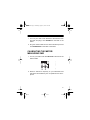
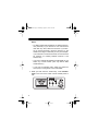
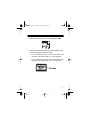
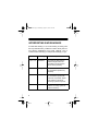
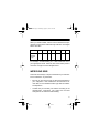
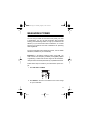
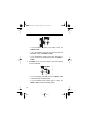
21-534.fm Page 1 Thursday, August 5, 1999 3:53 PM
Cat. No. 21-534
OWNER’S MANUAL
Please read before using this equipment.
CB/High-Frequency Ham
Power SWR Meter
21-534.fm Page 2 Thursday, August 5, 1999 3:53 PM
INTRODUCTION
Your RadioShack CB/High-Frequency Ham Power SWR
Meter helps you tune your CB or amateur radio system for
the best performance.
CB and amateur radio systems work best when the antenna
system’s impedance closely matches the transmitter’s output impedance. The meter’s standing wave ratio (SWR)
function helps you trim your antenna to the precise length
that produces the maximum transmit power. The meter’s
power meter function measures your radio’s peak envelope
power (PEP) or average power.
Carefully read all of these instructions to get the best use
from this meter.
Warning: You can use this meter to make measurements on
equipment that uses high voltages. Carefully observe all
safety precautions provided with the equipment you are testing.
Note: You need a separate 50-ohm coaxial cable (such as
RG-58U) with a PL-259 connector connected to both ends
(such as Cat. No. 278-968, not supplied), long enough to
reach from your radio’s antenna jack to the back of the
meter.
© 1998 Tandy Corporation.
All Rights Reserved.
RadioShack is a registered trademark used by Tandy Corporation.
2
21-534.fm Page 3 Thursday, August 5, 1999 3:53 PM
CONTENTS
Measuring SWR . . . . . . . . . . . . . . . . . . . . . . . . . . . . . . . . .
Connecting the Meter . . . . . . . . . . . . . . . . . . . . . . . . . .
Calibrating the Meter/Measuring SWR . . . . . . . . . . . . .
Interpreting SWR Readings . . . . . . . . . . . . . . . . . . . . .
Improving SWR . . . . . . . . . . . . . . . . . . . . . . . . . . . . . .
4
4
5
8
9
Measuring Power . . . . . . . . . . . . . . . . . . . . . . . . . . . . . . . 11
Care and Maintenance . . . . . . . . . . . . . . . . . . . . . . . . . . 14
Schematic Diagram . . . . . . . . . . . . . . . . . . . . . . . . . . . . . 16
Specifications . . . . . . . . . . . . . . . . . . . . . . . . . . . . . . . . . 17
3
21-534.fm Page 4 Thursday, August 5, 1999 3:53 PM
MEASURING SWR
Measuring SWR shows you how much of your radio’s transmit
power is reflected from the antenna back into the antenna cable, generating heat and wasting power. With this information,
you can adjust the length of your antenna or antenna cable so
your antenna and radio combination can produce the maximum power they are capable of producing.
For more information about measuring SWR, see the ARRL
Handbook, available at your local library.
CONNECTING THE METER
To connect this meter to your CB or amateur radio and your
antenna, you need RG-58U coaxial cable (not supplied) with
a PL-259 connector on both ends (such as RadioShack Cat.
No. 278-968). The cable must reach from the back of the
meter to your radio’s antenna jack.
Follow these steps to connect the meter to your radio and antenna.
4
21-534.fm Page 5 Thursday, August 5, 1999 3:53 PM
1. Turn off your radio. Then disconnect the antenna from
the radio and plug it into ANTENNA on the back of the
meter.
2. Plug the coaxial cable into the radio’s antenna jack and
into TRANSMITTER on the back of the meter.
CALIBRATING THE METER/
MEASURING SWR
1. Turn on your radio. Then set FUNCTION on the front of the
meter to CAL.
2. Select a channel or frequency on your transmitter and
hold down its transmit key. Do not speak into the microphone.
5
21-534.fm Page 6 Thursday, August 5, 1999 3:53 PM
Notes:
• An SWR reading will be different for different frequencies (channels). If you transmit on one channel more
often than any other, select that channel. If you transmit on several channels, choose a frequency in the
middle of the range of channels you use. (For example,
if you transmit on all 40 CB channels, choose Channel
20, because it is midway between Channel 1 and
Channel 40.)
• If you use a CB that has sideband modes (SSB), do not
select any of these modes. (Use only AM for SWR
measurements.)
• If you have an amateur radio, select the continuous
wave (CW) or tuning mode to check the SWR.
3. While you hold down the transmit key, rotate CALIBRATION on the front of the meter until the needle points to
CAL.
6
21-534.fm Page 7 Thursday, August 5, 1999 3:53 PM
4. Release the transmit key, then set FUNCTION to SWR.
5. Press the transmit key again, then find the SWR by reading the appropriate scale on the meter.
• If your transmitter’s power is less than 20 watts, read
the lower scale (marked with an L on its right side)
• If your transmitter’s power is more than 20 watts, read
the upper scale (marked with an H on its right side)
7
21-534.fm Page 8 Thursday, August 5, 1999 3:53 PM
INTERPRETING SWR READINGS
An ideal SWR reading is 1.0, but this reading is usually possible only under laboratory conditions or with a dummy load. Actual antenna installations have higher readings. The information below will help you interpret the readings you get.
SWR
8
Efficiency
Interpretation
1.0 to 1.5
Excellent
The antenna cable and the
antenna length match the
transmitter’s output requirements almost perfectly.
1.5 to 2.0
Very good
The antenna, the cable, and
the transmitter operate very
efficiently.
2.0 to 3.0
Acceptable
The antenna, the cable, and
the transmitter operate with
some loss. If possible, adjust
your antenna or antenna
mounting system to improve.
Above 3.0
Inefficient
Adjust your antenna or
antenna mounting system to
improve efficiency.
21-534.fm Page 9 Thursday, August 5, 1999 3:53 PM
When you measure SWR, use this chart to determine the percentage of power that is wasted through reflection of the signal
back to the radio.
SWR
1.0
1.1
1.2
1.5
2.0
2.5
3.0
Ref.
Power
(%)
0
0.22
0.8
4.0
11.1
18.4
25.0
For example, an SWR reading of 1.5 also means that 4% of
your signal power is lost. However, 96% of the radio’s power is
more than enough for almost all applications.
IMPROVING SWR
There are several ways to improve the SWR of your radio/antenna combination. Try these first.
•
Be sure you are using the type of cable recommended for
your equipment. If the manufacturer recommends a 50ohm cable, do not substitute another type that has a different impedance.
•
Confirm that you mounted your antenna according to the
manufacturer’s instructions. The angle and the base
arrangement can affect the SWR reading.
9
21-534.fm Page 10 Thursday, August 5, 1999 3:53 PM
•
Adjust the length of your antenna according to the instructions provided by the manufacturer. A change of as little as
1
/8 inch can make a measurable difference.
•
See your radio and antenna’s owner’s manuals.
10
21-534.fm Page 11 Thursday, August 5, 1999 3:53 PM
MEASURING POWER
You can use your meter to show how much power your radio
is transmitting. You can use this information with the SWR
reading (see “Measuring SWR” on Page 4) to determine the
efficiency of your antenna and radio combination, or to make
sure that your antenna and radio combination are operating
within legal limits.
For more information about measuring power, see the ARRL
Handbook , available at your local library.
Important: To accurately measure power using SSB, you
must connect a low-frequency oscillator (not supplied) capable
of generating a 1000–1500 Hz tone signal to the transmitter.
This procedure should be performed by a qualified technician.
Follow these steps to measure your transmitter’s power output.
1. Set FUNCTION to POWER.
2. Set RANGE on the front of the meter to the correct range
for your transmitter.
11
21-534.fm Page 12 Thursday, August 5, 1999 3:53 PM
• If your transmitter’s power is 20 watts or less, set
RANGE to 20W.
• If your transmitter’s power is more than 20 watts but
200 watts or less, set RANGE to 200W.
• If your transmitter’s power is more than 200 watts, or
you do not know the transmitter’s power, set RANGE to
2000W.
3. Set MODE on the front of the meter to the correct setting
for your transmitter.
• If your transmitter uses SSB or CW, set MODE to PEP
to measure peak envelope power.
• If your transmitter uses another type of output, set
MODE to AVG to measure average power.
12
21-534.fm Page 13 Thursday, August 5, 1999 3:53 PM
4. If your transmitter does not use SSB, select a channel or
frequency on your transmitter and hold down its transmit
key. Do not speak into the microphone.
If your transmitter uses SSB, input a 1000–1500 Hz tone
signal from the low-frequency oscillator you connected to
the transmitter. Then, select a channel or frequency on
your transmitter and hold down its transmit key. Do not
speak into the microphone.
5. Read the power level by noting the needle’s position on
the correct POWER scale.
• If you set RANGE to 20W in Step 2, read the lower scale
(marked with an L on its right side)
• If you set RANGE to 200W or 2000W in Step 2, read the
upper scale (marked with an H on its right side)
Note: If the power level is extremely low within the range you
selected, set RANGE to a lower setting and repeat Steps 4 and
5.
13
21-534.fm Page 14 Thursday, August 5, 1999 3:53 PM
CARE AND MAINTENANCE
Your RadioShack CB/High-Frequency Ham Power SWR
Meter is an example of superior design and craftsmanship.
The following suggestions will help you care for your meter so
you can enjoy it for years.
Keep the meter dry. If it gets wet, wipe it dry immediately. Liquids can contain minerals that can
corrode the electronic circuits.
Handle the meter gently and carefully. Dropping
it can damage circuit boards and cases and can
cause the meter to work improperly.
Use and store the meter only in normal temperature environments. Temperature extremes can
shorten the life of electronic devices and distort
or melt plastic parts.
Keep the meter away from dust and dirt, which
can cause premature wear of parts.
Wipe the meter with a damp cloth occasionally to
keep it looking new. Do not use harsh chemicals,
cleaning solvents, or strong detergents to clean
the meter.
14
21-534.fm Page 15 Thursday, August 5, 1999 3:53 PM
Modifying or tampering with your meter’s internal components
can cause a malfunction and might invalidate the meter’s warranty. If your meter is not operating as it should, take it to your
local RadioShack store for assistance.
15
21-534.fm Page 16 Thursday, August 5, 1999 3:53 PM
SCHEMATIC DIAGRAM
(illus - show schematic diagram
of meter)
Notes:
1. All resistance values are indicated in “OHM”
3OHM).
(K=10
2. All capacitance values are indicated in “mF”
-6 mF).
(P=10
3. All diodes (
16
) indicated in 1K100-350.
21-534.fm Page 17 Thursday, August 5, 1999 3:53 PM
SPECIFICATIONS
Measurable RF Power ...................................... 1–2000 Watts
SWR:
at 25 Ohms load impedance ...................................... 2.0
at 50 Ohms load impedance ...................................... 1.1
at 100 Ohms load impedance .................................... 2.0
Impedance ................................................................ 50 Ohms
Frequency Range ................................................... 3–30 MHz
Minimum Input Power for Calibration ........................... 1 Watt
Power Meter Accuracy (at 50 Ohms load impedance):
5 Watts ............................................................. ± 0.5 Watt
50 Watts .............................................................
±
5
Watts
500 Watts ........................................................ ± 50 Watts
Dimensions (HWD) ...................... 2 17/32 ¥ 6 15/32 ¥ 4 1/16 Inches
(64 ¥ 165 ¥ 102 mm)
Weight ........................................................................ 10.9 oz
(310 g)
Specifications are typical; individual units might vary. Specifications are subject to change and improvement without notice.
17
21-534.fm Page 18 Thursday, August 5, 1999 3:53 PM
NOTES
18
21-534.fm Page 19 Thursday, August 5, 1999 3:53 PM
Limited Ninety-Day Warranty
This product is warranted by RadioShack against manufacturing defects in material and workmanship under normal use for ninety (90) days from the date of
purchase from RadioShack company-owned stores and authorized RadioShack franchisees and dealers. EXCEPT AS PROVIDED HEREIN, RadioShack MAKES NO EXPRESS WARRANTIES AND ANY IMPLIED
WARRANTIES, INCLUDING THOSE OF MERCHANTABILITY AND FITNESS
FOR A PARTICULAR PURPOSE, ARE LIMITED IN DURATION TO THE DURATION OF THE WRITTEN LIMITED WARRANTIES CONTAINED HEREIN.
EXCEPT AS PROVIDED HEREIN, RadioShack SHALL HAVE NO LIABILITY
OR RESPONSIBILITY TO CUSTOMER OR ANY OTHER PERSON OR ENTITY WITH RESPECT TO ANY LIABILITY, LOSS OR DAMAGE CAUSED DIRECTLY OR INDIRECTLY BY USE OR PERFORMANCE OF THE PRODUCT
OR ARISING OUT OF ANY BREACH OF THIS WARRANTY, INCLUDING,
BUT NOT LIMITED TO, ANY DAMAGES RESULTING FROM INCONVENIENCE, LOSS OF TIME, DATA, PROPERTY, REVENUE, OR PROFIT OR
ANY INDIRECT, SPECIAL, INCIDENTAL, OR CONSEQUENTIAL DAMAGES,
EVEN IF RadioShack HAS BEEN ADVISED OF THE POSSIBILITY OF SUCH
DAMAGES.
Some states do not allow the limitations on how long an implied warranty lasts
or the exclusion of incidental or consequential damages, so the above limitations or exclusions may not apply to you.
In the event of a product defect during the warranty period, take the product and
the RadioShack sales receipt as proof of purchase date to any RadioShack
store. RadioShack will, at its option, unless otherwise provided by law:
(a) correct the defect by product repair without charge for parts and labor; (b) replace the product with one of the same or similar design; or (c) refund the purchase price. All replaced parts and products, and products on which a refund is
made, become the property of RadioShack. New or reconditioned parts and
products may be used in the performance of warranty service. Repaired or replaced parts and products are warranted for the remainder of the original warranty period. You will be charged for repair or replacement of the product made
after the expiration of the warranty period.
(continued)
19
21-534.fm Page 20 Thursday, August 5, 1999 3:53 PM
(continued) This warranty does not cover: (a) damage or failure caused by or attributable to acts of God, abuse, accident, misuse, improper or abnormal usage,
failure to follow instructions, improper installation or maintenance, alteration,
lightning or other incidence of excess voltage or current; (b) any repairs other
than those provided by a RadioShack Authorized Service Facility; (c) consumables such as fuses or batteries; (d) cosmetic damage; (e) transportation, shipping or insurance costs; or (f) costs of product removal, installation, set-up
service adjustment or reinstallation.
This warranty gives you specific legal rights, and you may also have other rights
which vary from state to state.
RadioShack Customer Relations, Dept. W, 100 Throckmorton St., Suite 600,
Fort Worth, TX 76102
We Service What We Sell
3/97
RadioShack
A Division of Tandy Corporation
Fort Worth, Texas 76102
3A8
811081270A
Printed in China