1
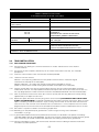
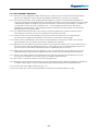
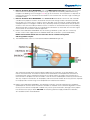
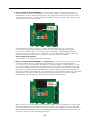
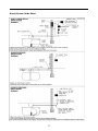
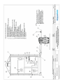
Installation
Operation
& Maintenance
Guidelines
for KingspanWater
Polyethylene Rainwater
Harvesting Tanks
GL0115P-03
ISSUE 04: DECEMBER 2009
GRAVITY SYSTEM
Contents
1
INTRODUCTION.................................................................................................................. 02
2
HANDLING AND STORAGE................................................................................................ 02
3
TANK INSTALLATION - (CIVIL WORK)............................................................................... 02
4
SYSTEM INSTALLATION - (PLUMBING & ELECTRICAL)................................................. 06
5
WARRANTY.......................................................................................................................... 13
HEALTH & SAFETY...................................................................................................................... 13
Enclosed Documents
2700 & 4500 Litre Tanks
DS0985P
RWH Direct Plastic Tanks 2700 & 4500 Litre Installation
DS0987P
Rainwater Gravity System Schematic
1800 Litre Tank
DS0995P
1800L Roto Rainwater Tank
DS0996P
1800L Roto RWH schematic (Gravity)
1
Introduction
1.1
These guidelines represent Best Practice for the installation of the above units. Many years of specialist
experience has led to the successful installation of thousands of units, it must be noted, however, that
these Guidelines are necessarily of a general nature. It is the responsibility of others to verify that they are
appropriate for the specific ground conditions and in-service loads of each installation. Similarly, a qualified specialist (e.g. Civil engineering consultant) must verify any information or advice given by our employees or agents regarding the design of an installation.
1.2
The unit is designed to be installed underground, as a minimum on a concrete slab with a concrete
backfill - unless the height of the water table means that additional hold down straps are required.
2
Handling & Storage
2.1.
Care must be taken to ensure that units are not damaged during delivery and handling on site.
2.2
The design requirements of our products will frequently mean that the centre of gravity of the unit is “offset”. Care must therefore be taken to ensure that the unit is stable when lifting. Rainwater may also collect inside units, particularly if they have been stored on site prior to installation, adding weight and increasing instability. Check units before lifting and pump out any excess water.
2.3
When lifting units, use webbing slings of a suitable specification. DO NOT USE CHAINS.
2.4
A suitable spreader bar should be used to ensure that units are stable and that loads are evenly distributed during lifting. When lifting units, a spreader bar should be used where the slings would otherwise be at an angle > 30 degrees to the vertical.
2.5
Lifting equipment should be selected by taking into account the unit weight, length and the distance of lift required on site.
2.6
We accept no responsibility for the selection of lifting equipment.
2.7
Whenever our units are stored or moved on site, ensure that the storage location is free of rock, debris and any sharp objects, which may damage the unit. The units must be placed on ground, which is flat and level
to evenly support the base of the unit. Do not roll units.
3
TANK INSTALLATION – (CIVIL WORK)
3.1
Siting
3.1.1 Where possible, take advantage of any gradient across a site to minimize the invert depth at the tank inlet, as this will reduce excavation. For frost protection a minimum invert depth of 500mm is recommended.
3.1.2 Avoid siting tanks in ground with a large gradient directly around the proposed position, as this can cause excessive ground pressure on the tank.
3.1.3
Our tanks are not designed to accept any traffic loads. A minimum traffic clearance of 2 metres must be
provided. If this is not possible the tank must be protected from superimposed loads, e.g. by a reinforced concrete surround and provided with an appropriate cover, which must not bear on the structure of the tank. Please contact and consultant civil engineer.
3.2
Before Installing Your Tank
3.2.1 Ensure Building Regulation approval.
3.2.2 Ensure ground porosity is suitable.
3.2.3 Inspect tank for damage before installation. Our tanks have been fully tested before despatch from our factory. Once the tank has been installed, we cannot accept claims for damage.
3.2.4 Check that you have the correct invert drain depth (neck height) of tank. A label indicates
the maximum permissible depth.
3.2.5 Check orientation and heights of inlet and outlets against drawings at the end of this manual.
3.2.6 The tank is supplied with a standard invert of 500 mm (allowing 75 mm for a manhole cover) from the top
of the inlet pipe.
02
3.2.7 DO:3.2.8 Use the correct backfill material.
3.2.9 Site the tank at the furthest practical location from habitable dwellings. Most building regulations
recommend a minimum of 7m.
3.2.10 Consider drainage falls, generally 1 in 60/70 between house and tank and maximum 1 in 200 for soakaways or other irrigation systems.
3.2.11 Lift the tank using ropes or slings through both of the shackles fitted either side of the neck.
3.2.12 DO NOT:3.2.13 Subject the tank to impact or contact with sharp edges.
3.2.14 Exceed an invert depth of:
i. 1.0m for 2,700 & 4,500L Tanks, Via brick work.
ii. 2.0m for 1800L Tank, Via brick work.
3.2.15 Install in trafficked areas without a suitable backfill design.
3.2.16 Site the tank so that it is subjected to excess ground pressure (e.g. sloping sites) or applied loads such as may be generated by the proximity of vehicular traffic.
3.2.17 Lift using only one lifting point.
3.2.18 Fill an unsupported tank.
3.3
Installation – General
3.3.1 When units are installed in unstable ground conditions where movement of the surrounding material and/or unit may occur, the connecting pipe work should be designed to minimise the risk of damage from differential movement of the unit(s) and/or surrounding material.
3.3.2 For units with burial depths greater than 1000mm from cover level to the top of the unit, specific site
conditions should be taken into consideration and the backfill designed to bear any loads which may be applied during and after installation to prevent the tank being subjected to these loads.
3.3.3 The excavation must be deep enough to provide bedding and cover depth as determined by the type of
surface pavement and loading. Asphalt and concrete pads should extend a minimum of 300mm
horizontally beyond the unit in all directions.
3.3.4
In situations where the excavation will not maintain a vertical wall, it will be necessary to shore up the side walls of the excavation with suitable trench sheets and bracing systems to maintain a vertical wall from the bottom to the top of the excavation. DO NOT completely remove the shoring system until the backfilling is complete. These sites should be considered as wet sites.
3.3.5 In areas where the water table is above the bottom of the excavation and/or the excavation is liable to flood, the excavation should be dewatered using suitable pumping equipment and this should continue until the installation is complete.
3.3.6 During installation care must be taken to ensure that the body of any unit is uniformly supported so that point loads through the unit are avoided.
3.3.7 The Concrete Specification is a general specification. It is not a site specific installation design.
03
GENERAL CONCRETE SPECIFICATION
IN ACCORDANCE WITH BS EN 206-1 ( BS 8500-1)
TYPE OF MIX
PERMITTED TYPE OF CEMENT
PERMITTED TYPE OF AGGREGATE
(coarse & fine)
(DC) DESIGN
BS 12 (OPC): BS 12 (RHPC): BS 4027 (SRPC)
BS 882
NOMINAL MAXIMUM SIZE OF AGGREGATE
20 mm
GRADES:
REINFORCED & ABOVE GROUND WITH HOLDING
DOWN BOLTS
REINFORCED (EG. FOR HIGH WATER TABLE)
UNREINFORCED (NORMAL CONDITIONS)
MINIMUM CEMENT
C30
270 - 280 Kg/M 3
CONTENT
C20
220 - 230 Kg/M 3
SLUMP CLASS
S1 (25mm)
RATE OF SAMPLING
READY MIX CONCRETE SHOULD BE SUPPLIED
COMPLETE WITH APPROPRIATE DELIVERY
TICKET IN ACCORDANCE WITH BS EN 12350-1
NOTE: STANDARD MIXES SHOULD NOT BE USED WHERE SULPHATES OR OTHER AGGRESSIVE
CHEMICALS EXIST IN GROUND WATER
3.4
C25 /30
C25 /30
C16 /20
Tank Installation
3.4.1 Dry Ground Conditions.
3.4.2 Excavate the site, allowing for a minimum clearance on all sides and base of the unit of 200mm
and level the base.
3.4.3 Ensure that the hole is kept dry. Should any rain or surface water collect in the hole, this should be
pumped out.
3.4.4 A base of at least 200mm of lean mix concrete should be provided.
3.4.5 Lower the tank into the hole:
ENV040:- use a rope sling underneath the tank (Under no circumstances should the sling be
attached to the inlet pipe or the outlet pipe).
ENV060 & ENV120:- use a rope sling through the lifting points provided on the tank
(Under no circumstances should the sling be attached to the inlet pipe or the outlet pipe).
3.4.6 Position the inlet pipe in line with the incoming drain. Note that the inlet and the outlet pipes are clearly embossed on the tank. The unique profile of the base will help to level the tank, but make sure the tank is in the truly upright position in order to maintain the 50mm head difference between the inlet and outlet pipes.
3.4.7 After any concrete in the base has taken up its initial set (usually after one day), ballast the tank by putting
approximately 0.5m depth of water into it.
3.4.8
Backfill the space around the tank with pea gravel or similar material (PEA SHINGLE ONLY TO BE USED
IN DRY SITE CONDITIONS). The backfill should be free from organic material, large stones, bricks or sharp objects. Backfilling should be carried out in layers, making sure that voids are not left under and around the sides of the tank and that there are no localized stress concentrations. It is most important that the installer progressively fills the tank with water to the level above the backfill in order to stabilize pressures on the tank.
3.4.9 See section 4 ‘System Installation’ for connecting all pipe work.
3.4.10 Backfilling can now proceed up to ground level in 300mm stages ensuring tank is ballasted in
all chambers as you go.
3.4.11 A galvanized lockable manhole cover (600x600mm) and frame is to be fitted to suit specific site loadings,
THE TANK MUST NOT BE LOAD BEARING. The top of the manhole should not be sat below the local ground level. If necessary you should use brick work above the tank to bring the cover up to ground level.
3.4.12 Venting is provided on all tanks and must be used, ventilation to be run above ground level and finished
with necessary rodent protection.
04
3.4.13 WET GROUND CONDITIONS:
3.4.14 Excavate a hole to appropriate depth allowing at least 300mm for lean mix concrete and hard-core base.
Allow for tank width plus at least 400mm with additional allowance for any necessary shuttering.
3.4.15 De-water the excavation using suitable pumping equipment. Ensure that the pump discharge does not
saturate the ground in the immediate vicinity. In wet ground conditions the installer should ensure that the base is adequate to support the weight of the tank and its contents. If the base of the excavation is unstable, i.e. running sand or similar, excavate an additional 250 – 300 mm below concrete levels and fill up with
compacted hard-core. Place a sheet of polythene over the hard-core and up the sides of the excavation
before putting in the concrete cradle.
3.4.16 Lay a bed of concrete (minimum 150mm thick) on top of the polythene at the base of the excavation.
De-watering is to continue until you are satisfied that the concrete has cured.
3.4.17 Lower the tank onto the concrete bed, ensuring that the inlet and outlet are in the correct position.
Ensure the tank is upright and then ballast it with water to a maximum of 500mm deep.
3.4.18 Haunch up the concrete bed at least 450mm all round the base, ensuring that all voids in the concrete are eliminated and at least 150mm of concrete is left below the tank base.
3.4.19 Backfill to the invert depth with concrete. Ensure that the water level inside the tank is maintained no more than 250-300mm above concrete backfill level. It is most important that the installer progressively fills the tank with water to a level above the backfill in order to stabilize pressure on the tank.
3.4.20 Backfill evenly all round the tank, consolidating in layers. The backfilling should start before the base has
hardened and be a single continuous operation so that the tank has a full concrete jacket without joins.
3.4.21 DO NOT use vibrating pokers to consolidate concrete. DO NOT discharge concrete directly on to tank.
Ensure that the concrete is not too wet and that is tamped in around the tank.
3.4.22 See section 4 ‘System Installation’ for connecting all pipe work.
3.4.23 Build up a shell of concrete around neck of tank to 150-200mm thickness before completing the backfill with a suitable material. Necks must be suitably braced whilst backfilling around this non-ballasted area.
3.4.24 Fit cover and frame. Apply surface finish e.g. turf.
3.4.25 Do not empty tank until the concrete backfill has cured. Tanks may be left filled with water.
05
4
SYSTEM INSTALLATION – (PLUMBING & ELECTRICAL)
4.1
Gravity (Header Tank) System Installation.
4.1.1
Please refer to the GRAVITY SYSTEM Guide Sheet (at the end of this section) throughout these instructions. As you are installing a GRAVITY system it is assumed that you have MAINS WATER SUPPLY available and you wish to use MAINS water in this scheme by the installation of a header tank. In all cases, this equipment should be installed by competent, qualified personnel and should comply fully with all the relevant regulations, particularly the current Water Regulations and the current edition of the IEE regulations concerning the safe installation of such equipment. Be safe.
4.1.2 It is assumed that you have read and understood the Tank Installation Instructions, the Tank is IN SITU but not backfilled, and you must now consider the installation of the pipe work and cable runs.
4.1.3
Please be aware that there are connections to the pump and depth sensor, located in the tank, which must exit via the turret. If you intend using extension rings on the tank turret please bear this in mind. If there is any doubt regarding the ability to carry out these connections due to such extensions, you may need to consider an access chamber. Consult with a qualified civil engineer in this circumstance, particularly regarding the
surface loading.
4.1.4 Study the GRAVITY Guide Sheet and decide on the following:
1) The route by which you will take the surface drain pipes back to the tank from the gullies and whether
you are fitting a Rain Water Filter or not.
2) The route of your Tank Overflow Pipe. Note.
3) The route and inverts for pipe work from any manifold chamber collection points or Rainwater Filter.
4) The location of the Control Panel. Note that this unit should be mounted under cover, protected from frost, and be located at a convenient height of between 1.5 meters and 2.4 meters above ground level. If you wish to mount the unit in any other location please contact ENVIREAU for further advice.
The following instructions, up to and including Item (9) involve essentially Civil and Plumbing
work. The Electrical Installation begins at Item (10).
Once you are confident in your choice of locations you should begin by laying in the pipe work and
electrical ducts as shown on the Guide Sheet. The collection pipes should be 110mm and should be
connected to the roof drainpipes via sealed gullies, which prevent the ingress of surface water.
WARNING. Surface water can contain many contaminants and the system will not function
correctly with contaminated water. Keep your installation clean, particularly the tank, to avoid blocked filters and valves etc. You may be forced by site conditions to install pipe work in a different order to that suggested below,
but for the sake of clarity the instructions follow the Guide Sheet sequence. The first stage is to install the pump plumbing pipe work.
NOTE. You are strongly advised to leave the installation of the pump itself until you are ready
to electrically connect it in to the Control Panel. See step (13) following.
5) Refer to the Guide Sheet DIAGRAM A. The pump outlet source is the tank connector supplied with
the tank. Make certain that it is securely tightened in to the tank turret. Cut the MDPE 25mm (black) pipe squarely and clean off rough edges. Use an insert in the end of the pipe if recommended by the supplier. Make sure that the pipe and tank connector are clean and free from grit and soil etc. Do not insert the pipe if the portion to be inserted is badly scratched or striated. With the collet loose on the tank
connector, insert the pipe fully home then tighten the collet. Once tightened, check the fitting nut, tank side, for tightness. (Do not over tighten.)
06
6)
Refer to the Guide Sheet DIAGRAM A. Lay in the MDPE pump outlet pipe according to your chosen route and ensure that bending radii are kept as large as possible to avoid kinking. Before terminating the pipe in the building, wash it through to void any grit or small stones. Fix and secure to a stop-cock or isolating valve close to, or convenient for connection to, the Control Panel. The next stage is the fitting of the Electrical Duct.
7)
Refer to the Guide Sheet DIAGRAM A. The electrical duct should be 110mm PVC and should be suit able for the purpose. The duct should enter the tank turret through the duct connection provided. Run the duct in its trench with as straight a route as possible, using the minimum number of bends with sweep-bend joints of 45 degrees maximum only if absolutely necessary. Feed the draw wire (or rope) as the duct is laid. Use accessible joint boxes if there is a need for an acute bend on entry into the building. Terminate the duct at a point close to, or convenient for connection to, the control unit. The next stage is the installation of the rainwater collection pipe work.
8)
Refer to the Guide Sheet DIAGRAM B. You are installing a GRAVITY system and so it is necessary
to take a mains water supply feed to the HEADER TANK and to connect in (as illustrated below).
NOTE. The illustration below does not show the weir or overflow arrangement
which regulations require.
9) The ENVIREAU float shown is of the recommended FLUIDMASTER type 747.
You should then couple up the incoming pump supply from the stop-cock, to the IN-LINE filter, and
then to the Control Panel. Fit the filter as shown on the Guide Sheet, and complete the connection to
the Envireau Inlet using a Compression Fitting. Do not tighten against the spigot. Use two spanners in
contra-rotation to compress the olive and affect a seal. Do not use soldered joints under any circumstances. You may use push-fit connections on the property side of the Control Unit but do not use push-fits anywhere on the pump side. The next stage is the completion of the electrical connections.
10) Refer to the Guide Sheet DIAGRAM C. The following instructions must be carried out by a competent, qualified person and must be to the relevant standards as laid down in the current IEE regulations. Failure to carry out this work to the required standards may cause system malfunction, damage or costly repairs. It could also cause injury or death. BE SAFE. The incoming electrical supply should be installed first,
all in accordance with the Guide Sheet.
07
11) Refer to the Guide Sheet DIAGRAM C. The main electrical supply should come from either the
Distribution Board, fused or with MCB Type C rated 16 amps, thence via a separate Residual Current Detector (RCD), or from a local switched fused spur with integral RCD. Remove the control unit lid and
identify the terminals within. The mains supply terminal block is marked L, N and E and is top left (facing) on the control unit Printed Circuit Board.
Note. Although the system can run from a 13 Amp switched socket outlet, this is not advised.
In all instances a separate RCD MUST be in circuit. The system draws approximately 4 amps at
240 volts A.C. Whatever cable is run to the local switch arrangement, the MAXIMUM cable size to
enter the control unit should be 1.5mm 2 flexible TRS. Use a suitable joint box to convert if necessary. Permanently isolate, by fuse removal, this supply until the total installation is complete.
Do not apply power until then.
The next stage is the locating and fitting of the display unit.
12) Refer to the Guide Sheet DIAGRAM C. The display unit is an important part of your system. Choose the location carefully. The unit is designed to be mounted “flush” using a plaster-depth back box,
or “surface” using a surface back box. The display unit should be located in a visible position, in an area that is often occupied. The display unit is wired back to the control panel, using standard “Alarm” cable. This cable should be four cores at 1 amp per core rating (7/0.2 mm each core. Core colours red, yellow, black, blue). The cable should be connected between the terminal block on the back of the display unit to the terminal block marked “DISPLAY” in the control panel. The terminal blocks at both ends are marked R for RED core, Y for YELLOW core, Bu for BLUE core and Bk for black core. The terminal block is
marked display and is top right (facing) on the control panel Printed Circuit Board.
(Note. If you wish to use the PUMP LOCK-OUT MODE or BMS contact on the display unit and you need to bring the feed from the contact back into the same location as the CONTROL unit, use 6 core cable. The two remaining cores go into the pair of terminals at the back of the display unit. See the document on NON-STANDARD SYSTEMS for details of the BMS CONNECTIONS and PUMP LOCK-OUT mode). The next stage is the wiring in (and installation) of the pump.
08
13) Refer to the Guide Sheet DIAGRAM C.
At this stage, the pump should not be in the tank. To install the pump you should take great care.
It is a HEAVY item. Be safe. Two persons will make the job much easier. Take the pump to the tank turret. Release the ties on the mains electrical cable. Uncoil the Hose. Draw the mains electrical cable through the duct along with another draw-wire (or rope) to pull through the sensor cable later. When the pump
cable is fully in place, with the waterproof connector accessible (on enough spare cable to reach ground level easily), the pump can be lowered carefully, on its rope, into the tank. Do not lower the pump by the electrical cable or by the hose. One person should hold on to the pump hose free end and should guide the other person, not allowing the cable to be trapped by the lowering pump. Once the pump is sitting on the tank bottom, the rope should be tied off to the turret bracket, just sufficiently taught to keep the
pump upright but not enough to suspend it. The pump hose should now be connected to the protruding thread of the tank connector. Do not over tighten. Run the pump electrical cable from the duct to the
control panel and wire it in to the terminals marked L,N and E, designated pump. The terminals are just below the MAINS IN terminals upper left on the PCB (facing).
NOTE. If you have extended the pump cables and have used oversized, armored or solid conductors to achieve this you must convert to the previously specified cable size using a joint box before entering the control panel. A suitable pump isolator switch is often used as a convenient joint box.
You are now ready to install and connect the depth sensor (often referred to as just sensor)
09
14) Refer to the Guide Sheet DIAGRAM C.
The depth sensor is a robust item but must not be subjected to excessive impact, crushing or stretching of the attached cable. To avoid these occurrences it is the last item to be installed.
NOTES.
a) The Sensor cable is of a pre-ordered length, which you have checked upon receipt.
b) It is NOT advisable to extend this cable by jointing. If it is absolutely necessary you must ensure that any joint is watertight and accessible.
c) There must be NO jointing of this cable in the tank turret.
d) Any use of cable not supplied by Envireau for the express purpose MUST be of a SIMILAR
specification. The minimum specification is 4 core (16/0.2mm per core, RED, YELLOW, GREEN, BLUE or NUMBERED) screened by braid or SWA. The outer insulation MUST be rated at 240v RMS.
e) The screen or SWA must be EARTHED at the control unit end only and must be electrically continuous with the screen on the sensor cable supplied.
To install the sensor, uncoil the cable fully and straighten on the ground surface. You are NOT advised to cut the cable to length at this stage. It is important that this cable is not unduly stretched so lubricate if necessary. Draw all the cable through the duct, along with another draw-wire (or rope) for future use if
necessary, until there is a minimum of three meters of cable in the tank turret. Do not leave excessive unused cable coiled in the turret or chamber. It is a trip hazard. Be safe.
Do not lower the sensor into the tank at this stage. Secure the sensor temporarily to the fitted turret bracket, out of the water.
Once the cable is through the duct it should be terminated in the Control Panel after cutting to length. Discard the unused cable. The sensor cable cores should be connected in to the SENSOR terminal block. This terminal block is below the display terminals, upper right (facing) on the PCB. The terminals are marked R for the RED core, Y for the YELLOW core, Bu for the BLUE core and Gn for the GREEN core.
15) You have now completed the installation of your GRAVITY system. Before proceeding to the final stage Set-up and Commissioning, you should check the following.
a) Are all pipe work joints secure?
b) Have you taken precautions to quickly isolate the electrical supply to the system?
c) Is the storage tank full (or at least half-full) of clean water, free from installation detritus?
d) Are you aware of the location of all items of equipment, particularly the display unit?
e) Have you completed the external plumbing to appliances?
Note. It is permissible to install a stop-cock within 0.5 meters of the outlet from the controller but there should not be less than 3 meters of pipe work in total to the system appliance(s), including the header tank, without the inclusion of a pressure vessel in the run.
10
16) Set-up and commissioning. It is essential that these instructions are carried out before
leaving the system with electrical power applied.
a) First of all, determine approximately the level of water in the storage tank i.e. Full, Half-full, etc. and confirm that the depth sensor is out of the water. Now TURN OFF the stop-cock on the pump incoming line before the in-line filter.
b) Apply power to the system and observe the display unit. The pointer on the display level indicator should read empty. (If it does not, investigate the connections to the depth sensor.)
c) Now lower the depth sensor into the tank and allow it to rest on the bottom. Observe the display level indicator again. The pointer will read either a “level” or will show a “fan-like” effect of flashing pointers.
d) You must now remove the lid of the controller and identify the setting controls along the bottom of the Printed Circuit Board. You must set the LEVEL indication using VR2.
e) To adjust the level display turn the small brass set-screw of VR2 CLOCKWISE to LOWER the reading, ANTI-CLOCKWISE to RAISE the reading. Note. If the Level Indicator is showing FLASHING pointers this is a HIGH reading (See “Troubleshooting”) and so you should turn VR2 clockwise. Set the display to
approximate to the actual water level in the tank.
f) Now remove the filter from the in-line filter carrier on the pump incoming pipe and VERY SLOWLY open the incoming stop-cock below the filter carrier. You will hear air rushing up the pipe from the pump. Be ready to turn off the stop-cock to avoid spillage from the filter carrier. Turn off the stop-cock when water wells up inside the filter carrier. Replace the filter and screw the parts together firmly. NOW OPEN THE STOP-COCK FULLY. Check for leaks.
g) Observe the display unit. The STATUS light may be illuminated. Ignore this indication during setting up. You must now set the PRESSURE switch point using VR8.
h) To set VR8, the pressurized indicator must first of all be extinguished. To do this you will now set the PUMP SWITCH-OFF pressure to a higher pressure than the pump can achieve. The pressurized indicator is the GREEN light nearest to VR8. TURN VR8 ANTI-CLOCKWISE UNTIL THE PRESSURISED INDICATOR EXTINGUISHES. If it is already unlit at initial observation then proceed to (i) below.
i) With the pressurized indicator extinguished and water in the external tank, the pump should be running. Check that this is the case by operating the ball-cock in the header tank or by operating any other
appliances on the same feed (e.g. external taps). Allow the header tank to FILL and the DEMAND
to cease.
j) NOW, turn VR8 clockwise until the pressurized indicator illuminates. You may turn VR8 up to 3 turns past this point to ensure pump switch-off on pressurization but if you turn the control too far the pump may fail to turn on when the system de-pressurizes due to demand. A reasonable overturn would be 1-2 turns clockwise from the pressurized indication point.
k) You have now completed set-up and commissioning. Test all appliances and check to ensure that the STATUS indicator light, which may have illuminated during set-up, has now extinguished again. If the
STATUS indicator light fails to extinguish within five minutes, switch off the system and go to the
“Troubleshooting” section.
SAFETY CHECK. Now that the system is commissioned you should check that the pump becomes disabled when the water level in the storage tank falls to a very low (EMPTY) level. To do this you should lift the sensor until it is approximately 7” (18mm) below the water surface. The pump should no longer operate on demand at this level, and the opening of ENVIREAU ball-cock in the header tank
will not cause the pump to start. If the pump still operates at this level, you may adjust VR5 slowly
anti-clockwise until the pump turns off.
11
Gravity System Guide Sheet
12
5
WARRANTY
Taken from ‘Kingspan’s Terms & Conditions of Sale’
The company will replace or, at its option, properly repair without charge any goods which are found to be defective and which cause failure in normal circumstances of use within a period of twelve months from the date of delivery.
This warranty is conditional upon:
(a) The Buyer notifying the Company of any claim within Seven days of the failure becoming discernible.
(b) The Company being allowed a reasonable opportunity to inspect the goods so as to confirm
that they are defective.
(c) The goods not having been modified, mishandled or misused and being used strictly in accordance with any relevant instructions issued by the Company.
The Company’s liability under this Clause is limited to the repair or replacement of the defective goods, and does not cover costs of transport, installation or associated site costs, if applicable.
The Company’s liability to replace or repair the goods is in lieu of and excludes all other warranties and
conditions, and in particular (but without limitation) the Company shall have no liability of any kind for
consequential loss or damage.
A Warranty Form is included in this package, to register your unit for Warranty. Please complete ALL sections of the Form, and return it at your earliest convenience.
For Technical queries please contact:
GB
Tel: +44 (0) 1296 633000
NI
Tel: +44 (0) 845 345 7178
For Service advice please contact Kingspan Environmental Services:
GB
Tel: +44 (0) 845 355 0555
Fax: +44 (0) 1264 325245
NI
Tel: +44 (0) 28 302 54077
Fax: +44 (0) 28 302 60046
HEALTH & SAFETY
These warnings are provided in the interest of safety. You must read them
carefully before installing or using the equipment.
These Guidelines represent Best Practice for the installation of our spherical tanks. Many years of specialist
experience has led to the successful installation of thousands of units. It must be noted, however, that these
Guidelines are necessarily of a general nature. It is the responsibility of others to verify that they are appropriate
for the specific ground conditions and in-service loads of each installation. Similarly, a qualified specialist (e.g. civil
engineering consultant or certified installer) must verify any information or advice given by employees or agents of
Kingspan regarding the design of an installation. It is important that this document is retained with the equipment
for future reference. Should the equipment be transferred to a new owner, always ensure that all relevant documents
are supplied in order that the new owner can be acquainted with the functioning of the equipment and the relevant
warnings.
INSTALLATION SHOULD ONLY BE CARRIED OUT BY A SUITABLY EXPERIENCED CONTRACTOR,
FOLLOWING THESE GUIDELINES. ELECTRICAL WORK SHOULD BE CARRIED OUT BY A QUALIFIED
ELECTRICIAN.
When covers are removed precautions must be taken against personnel falling into the unit. Should you wish to
inspect the operation of the equipment, please observe all necessary precautions, including those listed below,
which apply to maintenance procedures. Ensure that you are familiar with the safe working areas and accesses & that
the working area is adequately lit. Take care to maintain correct posture, particularly when lifting. Use appropriate
lifting equipment when necessary. Keep proper footing and balance at all times. Avoid any sharp edges. The removal
of sediment should be carried out by a contractor holding the relevant permits to transport and dispose of such
waste. The contractor must refer to the guidelines in this document.
AS WITH ALL SITE WORK, THE DANGERS OF WORKING WITH WATER AND ELECTRICITY POSE SEVERE
THREATS TO HEALTH, IF OBVIOUS AND FUNDAMENTAL PRECAUTIONS ARE NOT TAKEN. THEREFORE
IF YOU ARE IN ANY DOUBT REGARDING ANY OF THE FOLLOWING, PLEASE DO NOT HESITATE
TO CONTACT US.
13
180 Gilford Road, Portadown, Co. Armagh, Northern Ireland, BT63 5LF
Sales Hotline Tel: +44 (0) 28 3836 4444 Tel: +44 (0) 28 3836 4400 Fax: +44 (0) 28 3836 4445
Email: [email protected] or visit: www.kingspanwater.com or our company website: www.kingspanenv.com
College Road North, Aston Clinton, Aylesbury, Buckinghamshire HP22 5EW
Sales Hotline Tel: +44 (0) 1296 633000 Fax: +44 (0) 1296 633001
Email: [email protected] or visit: www.kingspanwater.com or our company website: www.kingspanenv.com