1
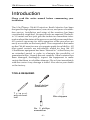
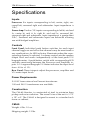
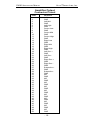
CM-60
INSTRUCTION
MANUAL
Monitor
Quality Cinema Products
Ultra★Stereo Labs, Inc. • 181 Bonetti Drive
San Luis Obispo, CA 93401
Telephone 805.549.0161 • e-mail [email protected]
CM-60 INSTRUCTION MANUAL
ULTRA★STEREO LABS, INC.
One Year Limited Warranty
★★★★★
Ultra★Stereo Labs, Inc. warrants that each product manufactured by it will be free from defects in material and workmanship
under normal usage for a period of one (1) year after its purchase
new from an authorized dealer. Our obligation under this
warranty is limited to repairing or replacing any product or
component which we are satisfied does not conform with the
foregoing warranty and which is returned to our factory, freight
paid, or serviced by one of our authorized contractors. The
foregoing warranty is exclusive and in lieu of all other warranties, whether expressed or implied. Such warranty shall not
apply to any product or component (A) repaired or altered by
anyone other than Ultra★Stereo Labs or an authorized service
contractor; (B) tampered with or altered in any way or subjected
to misuse, negligence or accident or (C) which has been improperly connected, installed or adjusted other than in accordance
with Ultra★Stereo Labs instruction.
Ultra★Stereo Labs, Inc.
181 Bonetti Drive
San Luis Obispo, CA 93401 USA
Telephone 805.549.0161
FAX 805.549.0163
e-mail [email protected]
Quality Cinema Products
© 1999 Ultra★Stereo Labs, Inc.
San Luis Obispo, CA, USA.
All Rights Reserved
0399
-2-
CM-60 INSTRUCTION MANUAL
ULTRA★STEREO LABS, INC.
Table of Contents
Introduction ....................................................... 4
Configuration ..................................................... 6
Installation ....................................................... 11
Specifications................................................... 14
Amplifier Pinouts ............................................. 15
Processor Pinouts ............................................. 16
CE Approved
Please record the following information for your records:
Model: ___________________ Serial Number: ___________
Date of Purchase: __________ Purchased from: __________
-3-
CM-60 INSTRUCTION MANUAL
ULTRA★STEREO LABS, INC.
Introduction
Please read this entire manual before commencing your
installation.
The Ultra★Stereo CM-60 Projection Booth Monitor has been
designed for high performance, ease of use, and years of troublefree service. Installation and setup of the monitors has been
considerably simplified. No special tools are required. The builtin VU meter and test jack give the technician immediate information about the status of the processor and all power amplifiers.
All controls necessary for daily operation of the processor are
easily accessible on the front panel. The components that make
up the CM-60 monitors are of computer grade for reliability. All
front panel controls are individually sealed for long life. All
Ultra★Stereo equipment has been “burned-in” at the factory for
an extended period in order to eliminate the possibility of
premature failure. Unpack the unit carefully. If the container has
been damaged, thoroughly inspect the equipment to make
certain that there is no hidden damage. File a claim immediately
with the carrier if any damage is found. Also advise your dealer
or the factory.
TOOLS REQUIRED
Small slotted
screwdriver
T r i m p o t
adjustment
tool
Wire strippers
No. 2 phillips
screwdriver
-4-
CM-60 INSTRUCTION MANUAL
ULTRA★STEREO LABS, INC.
You will need to supply the following materials:
• Shielded audio cable for connecting the CM-60 to the
cinema processor and power amplifier outputs.
• Four 10-32 x 1/2" screws to mount the CM-60 in the audio
equipment rack.
FEATURES
The CM-60 monitor has the following standard features:
• Six-Channel Monitoring - allows you to monitor either the
processor or power amplifier outputs to left, center, right,
surround left, surround right and subwoofer channels, in any
combination via the switch on the front panel (see illustration
on pg. 6 - switch 3.
• Input levels from processor and power amplifier can be
adjusted independently - no huge level jumps when switching
between processor and power amplifiers.
• Bargraph display may be calibrated to the reference level
for your theatre – the projectionist can see auditorium levels
instantly.
• Designed to work with bi or tri-amplified sound systems to
monitor the high, mid and low frequency outputs from the left,
center and right channels.
-5-
L
C
SL
-6-
1
CHANNEL SELECT
R
SR
SIX CHANNEL MONITOR
MODEL CM-60
Sub
2
10
0
VOLUME
9
8
1
2
6
7
5
3
4
CM-60 Front Panel
3
AMPLIFIERS
PROCESSOR
-20
-30
-40
+3
+2
+1
0
-1
-3
-5
-7
-10
4
VU
5
TEST
6
7
POWER
CM-60 INSTRUCTION MANUAL
ULTRA★STEREO LABS, INC.
Configuration
-7-
7. Power Switch
6. Internal Speaker
5. Test Jack - permits monitoring of the audio output of the CM-60. Inserting a mono 1/4"
phone plug here disables the internal speaker and routes the audio output to the Test
Jack. Do not connect any device here with less than 8Ω impedance.
4. VU Bargraph - displays the level of the selected channels. The VU Bargraph may be
calibrated by the rear panel trim adjustment (see 10, pg. 8). The VU Bargraph operates
independently of the volume control (2).
3. Processor/Amplifier Selector Switch - selects either the inputs from the cinema processor or power amplifiers for monitoring (see 4, 8 on pg. 8).
2. Volume Control - controls the volume of the internal or external speaker. The volume
control has no effect on VU Bargraph display.
1. Channel Select Buttons - pressing a Channel Select button causes the corresponding
LED to illuminate, and the signal from that channel to be monitored. Any combination
of six channels may be selected.
CM-60 INSTRUCTION MANUAL
ULTRA★STEREO LABS, INC.
FUSE
E
US
FUS
1
E F
-8-
FUSE
3A
RISK OF FIRE OR ELECTRIC
SHOCK DO NOT EXPOSE THIS
A P P L I A N C E TO R A I N O R
MOISTURE. DO NOT REMOVE
COVER. NO USER SERVICEABLE PARTS INSIDE. REFER
SERVICING TO QUALIFIED
PERSONNEL. FOR CONTINUED
PROTECTION AGAINST FIRE OR
SHOCK HAZARD REPLACE ONLY
WITH THE SAME FUSE TYPE
AND RATING.
WARNING: TO REDUCE THE
Input:
24VAC
50/60Hz
50VA
PROCESSOR OUTPUTS
2
3
AC AC E L C R Ls Rs SW E
POWER
CM-60 Monitor
4
PROCESSOR OUTPUTS
5 6 7
GAIN
CM-60 Rear Panel
8
AMPLIFIER OUTPUTS
9
10
LINE
AMPLIFIER OUTPUTS
OUT
Ls
Rl Rm Rh E + H/I E Ll Lm Lh E Cl Cm Ch E
Rs
+ -
SW
+ -
CM-60 INSTRUCTION MANUAL
ULTRA★STEREO LABS, INC.
-9-
10. Amplifier Outputs - connect these terminals to the power amplifier speaker outputs
corresponding to left, center, right, left and right surrounds. and subwoofer. Left, center
and right channels have high and low frequency inputs to use with bi-amplified systems.
9. Line Out - the left, center and right channel signals from the processors are summed
from amplifiers and fed to this terminal.
8. Amplifier Outputs - the amplifier outputs may be connected through a standard 50conductor flat cable and connector to J2. (See Amplifier Output Connection Pinout
table, pg. 15).
7. Amplifier Level - this trimpot adjusts the level of the input lines coming from the power
amplifiers.
6. Processor Level - this trimpot adjusts the level of the input lines coming from the
processor.
5. Bargraph Level - this trimpot adjusts the sensitivity of the front panel VU Bargraph
meter.
4. Processor Outputs - the processor outputs may be connected through a 25-pin D-sub
connector. (See Processor Output Connection Pinout table, pg. 16.)
3. Processor Outputs - connect these terminals to the cinema processor outputs corresponding to left, center, right, left and right surrounds, and subwoofer.
2. AC Input - 24V
1. Main Fuse - 3 Amp
CM-60 INSTRUCTION MANUAL
ULTRA★STEREO LABS, INC.
CM-60 INSTRUCTION MANUAL
ULTRA★STEREO LABS, INC.
PROCESSOR OUTPUTS
CM-60 Hookup Diagram
CM-60 Monitor
WARNING: TO REDUCE THE
RISK OF FIRE OR ELECTRIC
SHOCK DO NOT EXPOSE THIS
A P P L I A N C E TO R A I N O R
MOISTURE. DO NOT REMOVE
COVER. NO USER SERVICEABLE PARTS INSIDE. REFER
SERVICING TO QUALIFIED
PERSONNEL. FOR CONTINUED
PROTECTION AGAINST FIRE OR
SHOCK HAZARD REPLACE ONLY
WITH THE SAME FUSE TYPE
AND RATING.
Input:
24VAC
50/60Hz
50VA
POWER
FUSE
3A
LINE
PROCESSOR OUTPUTS
GAIN
AMPLIFIER OUTPUTS
OUT
H/I E Ll Lm Lh E Cl Cm Ch E
PROCESSOR OUTPUTS
AC AC E L C R Ls Rs SW E
AMPLIFIER OUTPUTS
Ls
Rl Rm Rh E + -
Rs
+ -
SW
+ -
FUS
G
N
D
G
N
D
G
N
D
G
N
D
E F
G
N
D
+
- +
Subwoofer
Surround Right
+
Surround Left
+
Right
+
Center
-
+
Left
- 10 -
G
N
D
E
US
FUSE
-
CM-60 INSTRUCTION MANUAL
ULTRA★STEREO LABS, INC.
Installation
Mount the CM-60
The ideal place for the CM-60 Monitor is in the sound rack or
projector console between the stereo processor and power
amplifiers. The terminal blocks on the rear of the CM-60 are
designed to facilitate the application of stripped and tinned wire
leads and are pluggable for easy service and trouble shooting.
Monitor Hookup
1. Power: Use 18AWG wire provided to connect the wall
transformer to the CM-60.
2. Processor Outputs: Use shielded wire to connect the linelevel outputs from the cinema processor to the CM-60. There is
one terminal for the "hot" signal from each channel, and one
common "E" (ground) terminal. The CM-60 also has a DB-25
computer style connector that matches the Ultra★Stereo DSP-60
processor, as well as many other processors. When the DB-25
connector is used, the processor output connections on the
terminal block should be left unconnected.
3. Amplifier Outputs: Use any suitable wire to connect the
power amplifier's speaker outputs to the "Amplifier Outputs"
terminals on the CM-60. The CM-60 has three inputs for each of
the three front channels for use with bi-amplified or tri-amplified
systems. For systems that are not bi or tri-amplified, use only the
low frequency inputs (Ll, Cl, Rl). For bi-amplified systems use
only the low frequency (Ll, Cl, Rl) and high frequency (Lh, Ch,
Rh) inputs. Unused inputs can be left unconnected. The surround and subwoofer inputs are balanced and may be used with
bridged or other non-grounded amp systems. The amplifiers may
also be connected to the CM-60 using a 50-conductor ribbon
cable and interface boards at each amplifier. Contact the factory
for more information on this convenient system.
- 11 -
CM-60 INSTRUCTION MANUAL
ULTRA★STEREO LABS, INC.
4. Crossover monitoring: The CM-60 also has line-level inputs
for monitoring the biamp crossovers. These connections are
available only on the DB25 connector. There are no screw
terminals. The three front channels have low and high frequency
inputs. The DSP-60 (and perhaps others) will simultaneously
transmit the full-range audio signal and the high and low
frequency crossover outputs. It may be necessary therefore to
disable the full range signal so only the post-crossover audio is
being monitored. There are jumpers inside the CM-60 for this
purpose (see pg. 13).
5. Split Surround Processors: For connection to split-surround
processors such as the Ultra★Stereo models JS-230, connect the
left and right processor outputs to the CM-60 surround left and
surround right inputs, respectively.
6. Line Output: For convenient connections to Ultra★Phonic or
other hearing impaired systems, the CM-60 has a line-level
output that combines the left, center, and right processor outputs.
Setting Levels
Run a pink noise test film such as Ultra★Stereo Type 1 or Dolby®
Cat. 69. Set the processor main fader and power amplifier levels
so the house speakers are playing back at the normal listening
level. Set the Processor/Amplifier switch to Processor and note
the reading on the front panel bargraph meter. Next, set the
Processor/Amplifier switch to Amplifier, and adjust the
Amplifier Level trimpot on the rear of the unit for the same
bargraph reading.
- 12 -
CM-60 INSTRUCTION MANUAL
ULTRA★STEREO LABS, INC.
Biamp Jumpers
R112
D29
RA2
RA1
R67
R4
- 13 -
AMPLIFIER
REMOVE JUMPERS TO USE
BIAMP PROCESSOR INPUTS
RA9
RA10
J1
BAR
U13
PROCESSOR
JP1 JP2 JP3
CM-60 INSTRUCTION MANUAL
ULTRA★STEREO LABS, INC.
Specifications
Inputs
Processor: Six inputs corresponding to left, center, right, surround left, surround right and subwoofer. Input impedance is
10kΩ.
Power Amp: Twelve (12) inputs corresponding to left hi, mid and
lo, center hi, mid & lo, right hi, mid and lo, surround left,
surround right and subwoofer. Input impedance is greater than
50kΩ. Surround and subwoofer inputs are balanced allowing
use with bridged amplifiers.
Controls
Front Panel: Individual push button switches for each input
channel toggle on and off so that channels may be monitored in
any combination. An LED indicator illuminates when the corresponding channel is selected. A volume control sets the speaker
output level and works independently of the front panel VU
bargraph meter. A push-button switch with corresponding LED
switches monitoring between the Processor and Amplifier inputs. A 14-segment bargraph VU Meter indicates the input level
from -40 to +3 VU.
Rear Panel: Three trimpots adjust the processor, amplifier and
VU meter input levels.
Power Requirements
24 VAC from external wall mount transformer.
100 and 240 V transformers are available.
Construction
The CM-60 Monitor is constructed of steel to minimize hum
pickup and noise radiation. The overall size of the unit is 3.72"
x 19" x 8". The CM-60 is designed to mount in a standard rack
frame or cabinet.
CM-60
Weight: 8 lbs. 10 oz.
Shipping weight: 12 lbs.
- 14 -
CM-60 INSTRUCTION MANUAL
ULTRA★STEREO LABS, INC.
Amplifier Output
Connector Pinout
Pin#
1
2
3
4
5
6
7
8
9
10
11
12
13
14
15
16
17
18
19
20
21
22
23
24
25
26
27
28
29
30
31
32
33
34
35
36
37
38
39
40
41
42
43
44
45
46
47
48
49
50
Function
Left Low
GND
Left Mid
GND
Left High
GND
Center Low
GND
Center Mid
GND
Center High
GND
Right Low
GND
Right Mid
GND
Right High
GND
Left Surr +
GND
Left Surr GND
Right Surr +
GND
Right Surr GND
Subwoofer +
GND
Subwoofer GND
N/C
GND
N/C
GND
N/C
GND
N/C
GND
N/C
GND
N/C
GND
N/C
GND
N/C
GND
N/C
GND
N/C
GND
- 15 -
CM-60 INSTRUCTION MANUAL
ULTRA★STEREO LABS, INC.
Processor Output
Connector Pinout
Pin #
1
2
3
4
5
6
7
8
9
10
11
12
13
14
15
16
17
18
19
20
21
22
23
24
25
Function
GND
Left
N/C
N/C
Center
N/C
N/C
Right
N/C
GND
GND
GND
N/C
GND
Left LF
Left HF
GND
Right LF
Right HF
GND
Center LF
Center HF
Surr L
Surr R
Sub
- 16 -
CM-60 INSTRUCTION MANUAL
ULTRA★STEREO LABS, INC.
- 17 -
CM-60 INSTRUCTION MANUAL
ULTRA★STEREO LABS, INC.
- 18 -
CM-60 INSTRUCTION MANUAL
ULTRA★STEREO LABS, INC.
- 19 -
CM-60 INSTRUCTION MANUAL
ULTRA★STEREO LABS, INC.
Ultra★Stereo Labs, Inc.
181 Bonetti Drive
San Luis Obispo, CA 93401 USA
Telephone 805.549.0161
FAX 805.549.0163
e-mail [email protected]
- 20 -
Quality Cinema Products
© 1996, 1998 Ultra★Stereo Labs, Inc.
San Luis Obispo, CA, USA.
All Rights Reserved