1
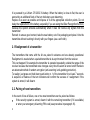
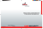
SPYBALL® 6829 Alarm + Immobiliser Thatcham cat. MC1 SPYBALL® 6809 Alarm Upgrade Thatcham cat. MC2>1 Meeting The British Insurance Industry’s Criteria for Motorcycle Security USER INSTRUCTIONS Thank you for choosing Spyball by Cobra. We recommend you read this guide carefully and keep it for future reference. 1 VEHICLE SECURITY Table of contents 1. 2. 2.1. 2.2. 3. 3.1. 4. 4.1. 4.1. 4.2. 5. 6. 7. 8. 8.1. 8.2. 9. 10. 11. 12. 13. 2 Kit composition Features of the radio transmitter Realignment of a transmitter Pairing of new transmitters Biker Recognition function Selection of the Biker Recognition function Arming / disarming of the security system Passive arming / disarming of the engine immobiliser (applies only to model 6829) Arming / disarming of the full security system without Biker Recognition function (use as a conventional transmitter) Arming / disarming of the full security system with Biker Recognition function Protection functions Temporary deactivation of the movement sensor Adjustment of movement detection sensitivity (this is a dealer operation) Alarm cycle Reduction of audible alarm power Check control function Alarm memory and diagnostics Anti-hijack function Back-up battery supply Service Mode “Turn indicator on” audible warning signal Selectable functions – Enabling and disabling procedures Automatic timed switch-off function (sleep function) Emergency disarming via PIN code 16.1. Reading the PIN code 16.2. Changing the PIN code 17. Troubleshooting guide 18. Technical data 14. 15. 16. 1. KIT COMPOSITION The kit includes A control unit with its protective metal shield Two remote control transmitters with Biker Recognition function A set of fitting accessories and a wiring harness A user manual (This is not a DIY product. Fitting instructions are available for download from the professional installer area of the Cobra website www.cobra-at.com) 2. FEATURES OF THE RADIO TRANSMITTER The radio transmitter (p/n 8742) has two buttons with different functions and a small LED in the middle, that flashes during transmission. It is protected against the use of code scanners and grabbers. 3 It is powered by a Lithium CR 2032 3V-battery. When the battery is close to flat, the user is warned by an additional flash of the turn indicators upon disarming. Replace it as soon as possible and dispose of it at the appropriate collection points. Do not delay the replacement of the battery, especially if you are using the Biker Recognition function, because the system activates automatically when it does not receive any signals from the transmitter! Remark: to ensure good contact, take the new battery out of its packaging and place it into the transmitter without touching it directly with your fingers (use a soft cloth). 2.1.Realignment of a transmitter The transmitters that come with the kit are paired in advance and are already operational. Realignment is needed when a paired transmitter is de-synchronised from the receiver. This can happen if for example the transmitter is operated repeatedly outside the range of the receiver because the transmitted code changes every time the alarm is turned on/off thanks to an advanced method of random encryption (anti-scanning / anti-grabbing protection). To realign, just press and hold down push-button n. 1 of the transmitter for at least 7 seconds. A sequence of flashes of the turn indicators will confirm the success of realignment. If the system is armed, it will disarm. 2.2. Pairing of new transmitters In the event of loss of failure, one or two new transmitters can be paired as follows: If the security system is armed, disarm it with the remaining transmitter (if it is available) or enter your emergency disarming PIN code (see procedure in paragraph 16). 4 Turn ignition on and wait 20 seconds. The dashboard LED illuminates and remains on about 3 seconds. Before the dashboard LED extinguishes, turn ignition off and then on again. A short and sharp sound signal confirms that the system is ready for pairing. The LED switches off. You have 6 seconds to complete the operation as described below. Press push-button n. 1 of a transmitter (or press both transmitters in turn, if you want to pair two). The LED illuminates shortly, to confirm that pairing has been successful. Once the operation is completed, turn the ignition off. If the ignition remains on, the system will automatically quit the pairing procedure In both cases the exit from the procedure is confirmed by a short sharp audible signal. Important: 1) For security reasons, each system can accept a maximum of two remote transmitters. 2) 5 Every pairing procedure disables the transmitters which the receiver had previously been paired with. Therefore: if you have lost a transmitter and you wish to pair a spare one, do not forget that the one which has remained in your possession has to be re-paired too (or it will stop working). If you are not able to acquire a replacement transmitter quickly, then simply repeat the process to re-pair your existing transmitter, and this will disable the missing transmitter. 3. BIKER RECOGNITION FUNCTION Besides its operation as a conventional remote control key, the transmitter can be used in Biker Recognition mode.This function is selectable. When the Biker Recognition function is enabled, the transmitter sends a coded signal at regular intervals (1.5 secs). The small LED on the transmitter flashes at the same rate. In this configuration the full security system (6829 = immobiliser + alarm, 6809 = alarm) activates automatically as the transmitter goes beyond the range of the receiver, i.e when the biker walks more than approximately 3 metres away from the parked motorcycle with the transmitter in his/her pocket. Similarly, it deactivates when the biker returns to his/her vehicle and the transmitter signal reaches the receiver. For more details regarding arming and disarming in Biker Recognition mode, please see also the information provided in the paragraphs below. 3.1. Selection of the Biker Recognition function This selection needs to be made on both the control unit and the transmitter. For the setting of the control unit, please refer to the chart included in paragraph 14, which provides general information about the possible configurations of the system (5 selectable functions). Additionally, the Biker Recognition function needs to be activated/deactivated via the transmitter: To activate, press and hold down both push-buttons at the same time until the small LED located on the transmitter starts to flash quickly for about 2 seconds. (*) To deactivate, press and hold down both buttons until you get a long flash from the LED (*). 6 If you expect to leave this function unused for a long time, you are strongly recommended to at least deactivate it from the transmitter, because this reduces the battery drain considerably and prolongs the life of the battery. (*): to avoid accidental arming (which may occur if the two buttons are not pressed exactly at the same time), carry out this operation at a distance from the motorcycle, beyond the range of the receiver. 4. ARMING / DISARMING OF THE SECURITY SYSTEM 4.1. Passive arming / disarming of the engine immobiliser (applies only to model 6829*) To conform with the British Insurance Industry’s Criteria for cat. MC1 security systems, the immobiliser section always activates automatically 27 secs after the motorcycle’s ignition has been turned off, whether the full system is activated or not. This is confirmed by a short flash of the turn indicators. To disarm the engine immobiliser, turn the ignition on, wait for the LED to start flashing quickly, then press push-button n. 1 of the transmitter (there is no need to press the button if the Biker Recognition function is activated). Disarming is confirmed by a long flash of the turn indicators. (*): The 6809 has no immobiliser function. It is a Thatcham cat. MC2 intended for fitment to motorcycles pre-equipped with a cat. 2 immobiliser. 7 1 alarm upgrade, 4.2. Arming / disarming of the full security system without Biker Recognition function (use as a conventional transmitter) To activate the full system (6829 = immobiliser + alarm, 6809 = alarm), press push-button n. 1 of the transmitter once. This can be done also if the immobiliser has already armed passively (Spyball 6829). Arming is confirmed by: Three short flashes of the turn indicators. Three sharp sound signals (if this function is enabled – see paragraph 14) (*) The dashboard LED lights up. The LED permanently illuminates for about 60 seconds. This is the arming period, which allows for the stabilisation of the control unit (first 25 seconds) and for subsequent testing of the functions (35 secs) – see paragraph 8.2., “Check control function”. Once this period has elapsed, the LED starts flashing to indicate that the system is fully active. The immobiliser is already operational during the arming period. To deactivate the full system (6829 = immobiliser + alarm, 6809 = alarm), press push-button n. 1 of the transmitter once. Disarming is confirmed by: A long flash of the turn indicators (**) A deep sound signal (if this function is enabled – see paragraph 14) The dashboard LED extinguishes. If disarming is not followed by starting the vehicle, the immobiliser will re-arm as described in paragraph 4.1 (Spyball 6829). 8 (*) Three additional sound signals in quick succession indicate that there is an irregularity in peripheral protection (e.g. the seat is open, the side stand is up), which will be disabled during that arming period. (**) A short additional flash indicates that the battery is low and needs replacement. 4.2. Arming/disarming of the full security system with function Biker Recognition Once the ignition is turned off, the full security system (6829 = immobiliser + alarm, 6809 = alarm) activates automatically within 21 seconds of the transmitter leaving the operating range of the receiver (about 3 meters). If the immobiliser has already armed passively (Spyball 6829), it is followed by the activation of the alarm section. Arming is confirmed by: Three short flashes of the turn indicators. Three sharp sound signals (if this function is enabled – see paragraph 14) (*) The dashboard LED lights up. The LED remains permanently illuminated for approximately 25 seconds. This is the short arming period, which the unit needs to stabilise. Once this period has elapsed, the LED starts flashing, to indicate that the system is fully active. The immobiliser (Spyball 6829) is already operational during the arming period. 9 If the Biker Recognition function is activated, the disarming of the alarm section is also automatic as the biker returns to the protected vehicle and the transmitter signal reaches the operating range of the receiver. For security reasons the immobiliser remains on and can be deactivated only following the procedure described at paragraph 4.1. (Spyball 6829). The disarming of the alarm section is confirmed by: A long flash of the turn indicators (**) A deep audible tone (if this function is enabled – see paragraph 14) The dashboard LED extinguishes. (*) Three additional sound signals in quick succession indicate that there is an irregularity in peripheral protection (e.g. the seat is open, the side stand is up), which will be disabled during that arming period. (**) A short additional flash indicates that the battery is getting low and needs replacing. 5. PROTECTION FUNCTIONS Dual engine immobilisation (Spyball 6829). Twenty-seven seconds after the ignition has been turned off, the immobiliser activates automatically and inhibits two vital circuits of the motorcycle’s electrical system. Starting becomes impossible. This function prevents the motorcycle from being driven under its own power by an unauthorised person. Peripheral protection. The system has a negative instantaneous alarm trigger input for contact switches (not supplied). These can be fitted to for example the seat or the topcase. Any attempt to gain access to the protected area will trigger the alarm. The trigger polarity is selectable (positive or negative), so that the storage compartment under the seat can be also protected by sensing the positive signal that controls the illumination of the courtesy light. 10 Movement detection. Triggers the alarm in the event of for example lifting, towing, forcing the steering lock by means of a revolutionary sensor (Spyball® patent) that detects changes in the motorcycle’s position over 360 degrees. Ignition lock tamper protection. Triggers the alarm if the ignition is turned on while the system is armed. Anti-sabotage protection (see also paragraph 11). In the event that the normal power supply is interrupted (for example if the cables of the motorcycle battery are cut), the integrated back-up battery allows the alarm system to sound (if armed) and signal sabotage. 6. TEMPORARY DEACTIVATION OF THE MOVEMENT SENSOR The system can be armed without activating the movement sensor. This facility may be useful to prevent a false alarm when anti-theft protection is required but the motorcycle is subject to movement (for example on a ferry). Procedure: Press push-button n. 1 to arm the system. Within 25 seconds press push-button n. 2. A sharp audible signal will confirm that the sensor has been deactivated. The cancellation is temporary and is valid for an arming period only. The movement detection function is reinstated the next time the system is armed. 11 7. ADJUSTMENT OF MOVEMENT DETECTION SENSITIVITY (this is a dealer operation) The movement detector can be adjusted to 8 different levels of sensitivity to displacement and 8 different levels of sensitivity to shock. The detector is fine-tuned for optimal performance by the dealer upon installation. Please consult your dealer if you require a different setting. 8. ALARM CYCLE Any irregularity that is detected by: the peripheral protection circuit (e.g. the opening of a protected storage compartment or case) the movement sensor (e.g. an attempt to drag the motorcycle away) the ignition lock tamper protection circuit (e.g. an attempt to force the lock) generates a 30-sec. alarm cycle. The alarm condition is signalled by the 114dB piezoelectric siren that is integrated within the device (sound warning) as well as by the flashing of the turn indicators (visual warning). After that the device automatically returns to the set condition. During the alarm condition pressing the remote control button n. 1 once will simply silence the siren and stop the indicators, leaving the system armed and ready to detect further irregularities. To disarm the system, press the push-button twice. For environmental protection, the alarm cycles in an activation period are limited to a maximum of 10/sensor trigger input. 12 8.1. Reduction of audible alarm power The volume level of the alarm can be reduced when the motorcycle is parked in areas where noise pollution needs to be minimised. When arming, keep push-button n. 1 of the transmitter pressed for about 7 seconds. Upon arming, keep push-button n. 1 pressed for about 7 seconds. The reduction of the sound power is confirmed by two deep short audible signals. This setting is valid for one arming period only. 8.2. Check control function During the arming time the protection functions of the system can be tested without generating an alarm cycle. Arm the system, wait 25 seconds to allow for stabilisation, then test the protection functions as appropriate during the remaining 40 seconds: a) b) c) 13 If the instantaneous alarm trigger input has been used to protect a case or the storage compartment under the seat, simulate the removal / opening. If the simulation is detected correctly, it is signalled by sharp audible signals. Test the movement sensor, by e.g. simulating an attempt to force the steering lock, dragging the motorcycle or tilting it up from the side-stand to vertical. If the simulation is detected correctly, it is signalled by sharp audible signals. If required, adjust sensitivity. Turn ignition on. If the ignition lock tamper protection circuit works properly, you will hear a sequence of sharp audible signals. 9. ALARM MEMORY AND DIAGNOSTICS If the security system has been triggered during your absence, upon disarming you will be warned by different audible signals, depending of the nature of the alarm cause: a) 1 audible signal = tampering with the ignition lock, unauthorised access to a protected compartment / case (instantaneous trigger input), cut of power supply b) 2 audible signals = lifting or dragging the motorcycle c) 3 audible signals = a + b The warning signal remains stored until the end of the inhibition time (60 secs) that follows the subsequent arming. 10. ANTI-HIJACK FUNCTION This function has been designed in response to the fast growing phenomenon of vehicle hijacking, typically while the driver is waiting before a stop sign or at traffic lights. The system switches to anti-hijack mode if the stolen motorcycle is running and the victim of the seizure is still in possession of the remote control transmitter with enabled Biker Recognition function. After the coded signal from the transmitter has been absent for 2 minutes, the siren starts to sound – firstly at low volume rising to full volume – and the turn indicators flash in an uninterrupted sequence of alarm cycles. When the motorcycle ignition is turned off, the complete security system arms itself automatically and engine starting becomes impossible. Disarming is only possible via the remote control or the emergency disarming PIN code. 14 Remark: the same will happen if you leave the range of the transmitter ignition of your motorcycle is on. while the Important: To benefit from this functionality, remember to ALWAYS keep the transmitter on your person in a pocket or wallet. NEVER attach it to the ignition key of the motorcycle! This function is also selectable and can be enabled or disabled as chosen by the user. Please refer to the table included in paragraph 14, which provides general information about the possible configurations of the system (5 selectable functions). 11. BACK-UP BATTERY SUPPLY The 6829 is equipped with internal Ni-MH back-up batteries that are automatically recharged when the motorcycle is driven. In the event that normal power supply is interrupted (e.g. in the event that the cables of the motorcycle battery are cut), the integrated back-up battery will allow the alarm system to sound (if armed) and will signal any sabotage. When the power supply is reinstated, the system sets itself to the same status (armed/disarmed) as it was before the interruption. 12. SERVICE MODE If you are using the transmitter in Biker Recognition mode and you need to have your motorcycle serviced but you prefer not to leave the transmitter with it, this quicker procedure 15 will allow you to temporarily disable automatic arming / disarming and the anti-hijack function without entering the selection procedure (Service set-up). Disarm the system via the emergency disarming PIN code (see paragraph16). The system sets itself to service mode: The Biker Recognition signal is over-ridden, the alarm will not activate automatically; The immobiliser remains active (Spyball 6829). The Biker Recognition operation mode will be reinstated the first time push-button n. 1 is pressed again. In the meantime you will hear four short sharp audible reminder signals every time the ignition is turned off. 13. ”TURN INDICATOR ON” AUDIBLE WARNING SIGNAL This ancillary function does not relate to anti-theft protection, but it can make riding easier and safer. If you enable it, the system will remind you with audible warning signals after a turn indicator has been flashing for more than 24 seconds. The procedure of selection is described in paragraph 14. 14. SELECTABLE FUNCTIONS – ENABLING AND DISABLING PROCEDURES The functions listed below are selectable and can be enabled or disabled as chosen by the user. The set-up is stored until a different configuration is selected. Biker Recognition (see paragraph 3) On/off audible signals (see paragraph 4) “Turn indicator on” audible warning signal (see paragraph 13) 16 - Anti-hijack function (see paragraph 10) Polarity of instantaneous alarm trigger input (this selection should be set up by the installer and must not be altered by the user once the security system has been fitted). Procedure: While the security system is disarmed, turn ignition on, press and hold down push-button n. 1 of the transmitter about 7 seconds, until the LED lights up, then release. The LED remains on about 3 seconds. During this lapse of time, press push-button n. 1 again. A short sharp audible signal confirms that the procedure has been initiated. The LED switches off, and then provides five different visual indications that relate to the five selectable functions. Please refer to the chart below: VISUAL INDICATION 1 flash 2 flashes 17 SELECTABLE FUNCTION Biker Recognition TO SELECT TO DESELECT CONFIRMATION SIGNAL CONFIRMATION SIGNAL Press push-button n. 1 of the transmitter after the first flash Three (3) sharp audible signals follow Arming and disarming Press push-button n. 1 of audible signals the transmitter after the second flash Three (3) sharp audible signals follow Press push-button n. 2 of the transmitter after the first flash One (1) sharp audible signal follows Press push-button n. 2 of the transmitter after the second flash One (1) sharp audible signal follows 3 flashes 4 flashes 5 flashes “Turn indicator on” audible Press push-button n. 1 of warning signal the transmitter after the third flash Three (3) sharp audible signals follow Anti-hijack function Press push-button n. 1 of the transmitter after the fourth flash Three (3) sharp audible signals follow Polarity of the Press push-button n. 1 of instantaneous alarm the transmitter after the trigger input (for dealer fifth flash use only) Positive polarity Press push-button n. 2 of the transmitter after the third flash One (1) sharp audible signal follows Press push-button n. 2 of the transmitter after the fourth flash One (1) sharp audible signal follows Press push-button n. 2 of the transmitter after the fifth flash Negative polarity Once the selections are finalised, a long low audible sound will confirm that they have been entered successfully. Note1): If you wish to modify any functions, you can reset them individually without needing to reset all 5 functions. Note 2): in the event of an error, turn ignition off to quit without making any changes. Note 3): do not alter the polarity of the instantaneous alarm trigger input (5 flashes) as set up by the installer, or this protection function will stop working. Note 4): the audible on/off signals are illegal in some Countries. Please check your local regulations and set up the system accordingly. 18 15. AUTOMATIC TIMED SWITCH-OFF FUNCTION (SLEEP FUNCTION) Although the current consumption rate of Spyball security systems is extremely low, another special feature has been implemented with the purpose of protecting the battery of your motorcycle: the radio receiver that is integrated within the unit switches off automatically after the motorcycle has been unused for 7 days and the current consumption rate drops considerably. When it is in sleep mode, the alarm system does not therefore react to the radio transmitter. In order to reinstate the normal functions of the device: If the system is disarmed, turn ignition on; If the system is armed, turn ignition on and press push-button n. 1. If the transmitter is not available, enter the emergency disarming pin code as described in paragraph 16. If turning the ignition on is not followed by pressing the transmitter on/off button or the pin code is not entered correctly, the siren will sound. 16. EMERGENCY DISARMING VIA PIN CODE In the event of loss or failure of the radio remote control, you can deactivate the security system by means of the procedure below, using the PIN code you can find on the last page of this manual or the replacement code that you may have entered (see paragraph 16.2.). The final page of this manual includes also a quick description of the disarming procedure; we recommend that you record the PIN code there, then cut out the card and keep it in your wallet for future reference. 19 If the full system is armed: 1. Turn ignition on. The alarm starts to sound. 2. Wait. The alarm stops. The LED switches off, then it starts to flash slowly. 3. Count the number of flashes. As soon as the number of flashes equals the first number of your PIN code, turn the ignition off (for example, if the first number of your code is 3, then wait for the LED to flash 3 times before turning the ignition OFF). The LED switches off. 4. Within three seconds, turn the ignition on again. Count the number of flashes. As soon as the number of flashes equals the second number of your PIN code, turn the ignition off (for example, if the second number of your code is 10, then wait for the LED to flash ten times before turning the ignition OFF). The LED switches off. 5. Enter the remaining numbers of the PIN code using the same procedure. In the event of an error, an alarm cycle will follow. At the end of the alarm cycle you will be able to repeat the procedure. ONCE ALL THE DIGITS HAVE BEEN ENTERED CORRECTLY, THE SYSTEM DISARMS WITH A LONG BLEEP AND THEN SWITCHES TO SERVICE MODE (see paragraph 12). If only the immobiliser is armed (Spyball 6829): 1. 2. 3. 20 Turn ignition on. The LED flashes quickly for 12 secs. Wait. The LED switches off, then it starts to flash slowly. Enter the digits of the PIN code using the same procedure as described above. In the event of an error entering the first two digits, the LED will start to flash quickly. Turn the ignition on and repeat the procedure. ONCE ALL THE DIGITS HAVE BEEN ENTERED CORRECTLY, THE SYSTEM DISARMS WITH A LONG BLEEP AND THEN SWITCHES TO SERVICE MODE (see paragraph 12). 16.1. Reading the PIN code If you have lost the PIN code but you have a working transmitter, you can recover the code with this simple procedure: While the system is disarmed, turn ignition on then press and hold down pushbutton n. 1 of the transmitter about 7 secs. The LED illuminates about 3 seconds, then it switches off for a short time and subsequently displays 4 sets of flashes. Count and note the number of flashes in each set. Those are the numbers of the PIN code. The end of the reading is confirmed by a short sharp audible signal. 16.2. Changing the PIN code If you wish, you can replace the original PIN code with one of your choice. The procedure is described below: While the system is disarmed, turn the ignition on then press and hold down pushbutton n. 1 of the transmitter about 7 seconds. The LED illuminates about 3 seconds. During this lapse of 3 seconds, press push-button n. 2. A short sharp audible signal confirms you have entered the procedure. The LED extinguishes, then it starts to flash slowly. 21 Count the flashes. As soon as you reach the number you have chosen as the first number of your PIN code, turn the ignition off. Turn the ignition on again and follow the same procedure to select the 3 remaining numbers. A short sharp audible signal will confirm that the procedure has been completed successfully. Read the code you have entered (see paragraph 16.1.) to make sure it is correct, then record it. Note 1): You can select digits between 1 and 18. Once the LED has flashed 18 times, the procedure stops and needs to be repeated: Note 2): To quit the procedure without making any changes, turn the ignition off before the new code is completed. 17. TROUBLESHOOTING GUIDE Malfunction Recommended inspections / operations The alarm does not respond to the transmitter. - 22 Make sure the system has not entered the sleep cycle (see paragraph 15) Operate the transmitter closer to the unit (the area might be affected by noise interference with the radio signal) Replace the transmitter battery Realign the transmitters (see paragraph 2.1. ) If none of these operations is successful, contact a The alarm/immobiliser is disarmed, but the motorcycle will not start - The system is not triggered by moving/lifting the bike - Spyball dealer (in the meantime, if the system is armed, disarm it with the PIN code (see paragraph 16) Make sure the motorcycle is in neutral gear Make sure the kill switch is in the RUN position Make sure the main ignition fuse in the motorcycle is intact Make sure the motorcycle battery is charged Some models will only start with the side stand up or the clutch lever pulled in – please check If none of these operations is successful, contact a Spyball dealer Has the inhibition time elapsed? Is the movement detector activated (not deselected)? If necessary, please adjust the movement detector (see paragraph 7.) If none of these operations is successful, contact a Spyball dealer 18.TECHNICAL DATA Power supply (control unit) Current consumption rate Back-up battery Capacity of engine immobilisation circuit Operating temperature 23 Nom. 12V Max 17V Min. 9V < 1 mA OFF; 1mA ON (including the LED) Rechargeable 7,2V 170mAh NiMH battery Max 6A -20°C / +85°C Siren sound power Size of the control unit Size of the transmitter Transmitter battery Transmitter battery life 114dB@1m 90x67x30mm 50x37x12,5 3V CR2032 Min.12 months (with Biker Recognition function on) RECOMMENDATION! Although designed to be resistant to water ingress (IPX5), this electronic equipment might be damaged by steam cleaning / high pressure washing. Never direct the jet at the unit and protect it to prevent water infiltration. Diagrams, descriptions and features are only indicative. The manufacturer reserves the right to modify them without notice. The manufacturer will not be responsible for malfunctions/damages resulting from the negligence of the the supplied installation and operation instructions. The system must only be considered as a deterrent against attempted theft. 24 Environmental Protection The CR 2032 batteries from the transmitters should be disposed of responsibly at your local battery recycling centre (to be found at refuse collection centres and supermarkets). Warranty This product is protected by a 24-month warranty from the date of purchase as certified by a receipt or an invoice. The warranty will become null and void if any failure is caused by negligent installation or misuse, as a result of accidental damage or transportation or by anything other than a manufacturing defect. The warranty will also be overridden if the unit is tampered with by anyone not authorised by Cobra AT. In the event of incorrect fitting/misuse, the manufacturer will not be liable for any kind of direct or indirect damage to persons or objects. Warranty claims must be made through an authorised Dealer. 25 26 27 PIN: ……………………………………………………………… EMERGENCY DISARMING VIA PIN CODE If the full system is armed: 1. Turn ignition on. The alarm starts to sound. 2. Wait. The alarm stops. The LED switches off, then it starts to flash slowly. 3. Count the number of flashes. As soon as the number of flashes equals the first digit of your PIN code, turn ignition off (for example, if the first number of your code is 3, then wait for the LED to flash 3 times before turning the ignition OFF). The LED switches off. 4. Within 3 seconds, turn ignition on again. Count the number of flashes. As soon as the number of flashes equals the second digit of your PIN code, turn ignition off (e.g., if the second digit of your code is 10, then wait for the LED to flash ten times before turning the ignition OFF). The LED switches off. 5. Enter the remaining digits of the PIN code using the same procedure. In the event of a error, an alarm cycle will follow. At the end of the alarm cycle you can restart the procedure. ONCE ALL THE DIGITS HAVE BEEN ENTERED CORRECTLY, THE SYSTEM DISARMS WITH A LONG BLEEP, THEN IT SWITCHES TO SERVICE MODE (see paragraph 12). If only the immobiliser is armed (Spyball 6829): 1. Turn ignition on. The LED flashes quickly for 12 secs. 2. Wait. The LED switches off, then it starts to flash slowly. 3. Enter the digits of the PIN code using the same procedure as described above. In the event of a error entering the first two digits, the LED will start to flash quickly. Turn ignition on and repeat the procedure. ONCE ALL THE DIGITS HAVE BEEN ENTERED CORRECTLY, THE SYSTEM DISARMS WITH A LONG BLEEP, THEN IT SWITCHES TO SERVICE MODE (see paragraph 12). 06DE3248A – 03/10 28 Cobra Automotive Technologies Via Astico 41 – 21100 VARESE – ITALY www.cobra-at.com