1
ITA
p
~
/\
A DIVISION
1-\...
VITA-SPA
DM INDUSTRIES
Hy Vit;e In...n8tiQMI
INSTALLATION
AND
OPERATING
INSTRUCTIONS
Member
~
~.
National
Spa & Pool
Institute
THESE INSTRUCTIO,NS
OF
MUST GO TO THE
END USER OF THIS EQUIPMENT.
IND!X
p.
GENERALINfORMATION
1.3
1.11NSTRUCTIONSU.LNe.1563
1.2
INSTALLATION
SAFETY
ELECTRICAL
1.3.2
1.3.1
Grounding
Ground
1.3.6
1.3.5
1.3.4120VoltSvstemReset
1.3.3
OPERATING
2.1
2.2
2.2.1
2.2.2240VoltSystem
ELeCTRlCALsERV'CE
LOCAT(NGVOURSPA
3.1
3.3
3.2
3.3.1
G&TTING
STARTINGYOURSPA
3.3.2
FEATURES
AND
~FETY
HEALTH
PowerlndicatorLight
Doorlnterlock
Hi9h
FEATURES.
INFORMATION.
Temperature
INSTRUCTIONS
i ~
:
,.
Limit
R-.t
1
1
2
2
2
2
3
3
3
..3
..4
..4
..4
'20VoltSystem
INSTRUCTIONS
5
ThermostatSetting
FQur
VOUR
ANO
Function
SPA
FUNCTIONS
Air READV
Switch.
TO -DX
USE.
SERIES.
""",
5
6
8
6
6
3.4
3.4.1
3.3.3
3.4.2
3.4.3
3.4.4
FEATuRes
TimeClockOption
Acc~ry.1
Jet8utton
SvStemButton
SystemlndicatorLight
TimeDelavFunctiDn
SpasideControl...,
AcceSS)ry
Automatic
FreezeProtection
Electronic
Heat..lndicatDrLight
FreezeProtection
Heat
AND
R~
#2Button
Thermostat.
FUNCTIONS
equipment
Indicator
Button
li~t
Prote«ltion
-L)(
SERIES.
,
;
...
,
6
7
7
, , , ,7
7
,
7
7
..;
7
7
,
7
,
1
7
7
7
,
'A
3.5
MAIN'f!NANC!
JETACTION
3.4.5
7
Tim8Clock
8
4.4.3
4.2
1
WIRINGDIAGRAMS
TROU8LESHOOTINQGUIDE
~ECIFICATION
GENERAL
4.1.4
4.1.2
4.1.3
4.1.5
4.1.6
SPA
4.1.1
4.3.1
FILTER
WATER
Winterizing
Equjpm.nt
CoYer
CI..ningYour~
Pump
DralningYourS~
Chemical
CARTRIDGE
4.3.2
4.3.4
4.3.3
Alkali~itv
P.'Control
HowToTestWat8f'
4.3.5
4.3.6
4.3.7
4.3.8
W.tetClarity
CalclumH8rdn
Colored
Foaming
4.3.9
4.3.10
Altematlve
AlQa8
MAINTeNANcE.MAINTENANCE.
Priming/W.ter
Treatment.
MAINTENANCE.
L8Yel
Vs
Prop8f'
Filtration.
'
Water/Scale
,
Disinfection
.,
Formation. ,
,
Method8
...;
.,
,
.,
,
,
B
8
8
8
8
B
9
9
g
9
'0
10
11
"
11
11
"
12
12
B8Ck Pock~
Back Pocket
.Back
Pocket
GENeRAL INFORMATION
1.1
REQUIRED INSTRUCTIONS
spa only). Should this cord fail to reach the
service, it shall become necessary to have an
electrician run a special No.12
wire, 20
ampere service to reach this power cord. Do
not use an extension cordl To do so will cause
the spa to operate improperly, and will damage
the pump, blOWer and possibly other
equipment Most important: THE USE OF
AN EXTENSION CORD WI LL VOID ~LL
WAR RANTI ESI
U.L. No.1563
OWNERS MANUAL
FOR ALL U.L. LISTED VITA SPA
LX and DX SERIES SYSTEMS
READ AND FOLLOW
BEFORE OPERATING
1.
Connect
ALL INSTRUCTIONS
THE SPA!
only to a grounded,
grounding
type
receptacle.
2.
3.
4.
5.
6
A pressure wire connector is provided on the
power box located inside the ~uipment
access door, to permit connection of a bonding
wire between this point and any metal equipment, metal encloSJre of electrical equipment,
metal wat.er pipe or conduit within five feet of
the spa as needed to comply with local
requirements. Bonding wire must be at leaSt a
No.8 AWG 98.4 (2mm2) solid copper wire.
1.2
1.
Ground Fault Circuit Interrupter: This equipmerit is provided with a Gfound Fault cireuit
Interrupter On the equipment pack inside the
aeeess dOOr. After tf1e ~8 is filled and befOre
use of your spa, with the plug connected to
the power, push the "test" button on the
ground fault interrupter , the power indicator
light located under the GFCI should turn "off".
Push the "reset" button. When the "reset"
bunon is pressed, the power indicator light
should turn "on". If the interrupter fails to
operate in this manner , there is a ground
current flowing, indicating the poSsibility of
an electrical shock. Disc:onnect the j)lug
from the receptacle until the source .of the
6reakClown fl8S &een iaentified and corrected.
Installation: The spa must be installed in such
a manner as to provide drainage of the
compartment for electrical components. You
need to pick a hard, flat and reasonably level
~rface. When properly installed, both skirt
and tub will rest flat on the supporting
~rface. Failure to do this can cau~ the skirt
to buckle or the tub to tilt and the side to
distort. We recommend a poured concrete pad
or similar hard surface.
SUpplying POWerto the Spa: After you have
selected your level SUrl8Ceand have placed the
spa in the position you desire. be SJre the
power cord pro\fided will reach your grounding
receptacle. The spa comes with a heavy duty
cord ( No.12 wire) arid is designed to plug into
a 120volt. 20 ampere, deaieBted circuit, (to the
1
DANGER. RISK OF ElECTAICAl
SHOCK.
Install at least S feet (1.52m) from all metal
surfaces. Do not permit any efectricaJ appliance such as a light, telephone, radio or television within S feet (1.52m) of a spa or hot tub.
SAFETY
AND
HEALTH
INFORMATION
Always enter and exit spa slowly and cau
tiously. Wet wrfaces will be slippery.
2.
Never use a spa while under the influence of
alCohol, anticoagulants, antihiStamines, v850constrictors,
vasodilators, stimulants, hypnotics, narcotics or tranquilizers.
3.
eecau. of the ever increasing popularity of
hot tub$ and spas, more p~ple of every age
are di~overing ttiis new, total relaxing, and
therapeutic activity. Everyone's body and
circulation sYSteM is different, ana responds
to hot water immersion in different ways. For
this reamn the amount of time spent safely in
your "of tub or ~a will wry. MoSt peOpte in
good health find the temperature 100°F to be
rewarding and limit themselves to maks of
between 10-20 minutes. Long exposure may
result in nausea, dizziness or fainting. Before
you use your hot tub or spa, it would be
prudent to see your family dOCtor for
recommendations regardless of your age,
health, and medical history.
4.
Pregnant women and persons ~ffering from
heart disease, diabetes, high or low blood
pressure should not enter the spa without
prior medical consultation and permission
from their doctor .
5.
Unsupervised
proh ibited.
6.
Do not use the spa alone.
use by
children
~Ould
be
~
..
1.3.4 120 VOLT SYSTEM RESET
Tftis reset is a general system reset to protect
the 120 volt components of your spa. It is
identified 8S "Breaker" on the control panel
and is marked. with a 1120" designating maximum amperage the reMt will hold. Sh9uld a
~oft Occ.JiI ffiis reset will automatically pop
out. diSi:ontinuing eleCtrical power to 120
vOlt citQJitry. This reset muSt be manually
reset once the problem has been resolved.
1.3.5 POWER INDICATOR LIGHT
This light located under the G.F.C.I.
when your spa is powered.
iNStAllATtoN
2.1 LoCATiNG YOuR spA
Your spa dealer is your beSt r~rce
for
determing flOw DeSt to inStall
your
new
Spa, what power requirements are necesSary
and what preliminary site preparation must be
accomplished.
The spa must be installed in such a manner as
to provide drainage away from the spa. Putting
the spa in a depression could allow rain, overflow ot other casual water to flOOOthe equ ipment and create a wet cond it ion f9r the spa to
seat in.
is ON
1.3.6 HIGH TeMpERATuRE
LIMIT REseT
This heat reset button is loeated on tOp of the
heater housing and is identified as "Heater
Reset". This button is designed to pop out in
the event the water becomes too hot. If this
occurs, the high limit re~t will disc:ontinue
POwer to the electrical heating element. This
f~t
buttOn MuSt 58 manually depressed to
reset its funCtion. This can only be done when
the water has cooled down to about 80°F for
the reset to fiolo. The nigfi limit reset is
designed to protect againSt overheating in the
event the thermostat should fail to operate or
in the unlikely event the heater should remain
on without water flow.
The SJ)aneeds a hard, flat and level surface to
rest on. When properly installed, the bottom
of the spa will fit flush with the alpporti~
surface. FAILURE TO PROviDe A FLAT
SURFACE WILL CAUSE THE SPA TO
DISTORT, COLLAPSE OR DAMAGE THE
SKIRTINGI we fecommend a poured eoncrete
SlJrface Ot similar hard s.jrlace.
Consider the following
~ggeStions
selecting the ideal area for yotJr Spa:
S
J::~.I-- ::::,;,.--\
.J
\
\
~.
.-
' ~-::'1
,. \, ~
.-1
.--=:-:-
':
,
,.\
-..~
:':
:
~~"
'I
I
~
'
[J
,- ~ ~;
;
I
I
i
I
,
!
/
\
~
/
/-
.
~1
.l~
~..[J
I ~
.
c:.;.
~
, t
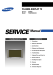
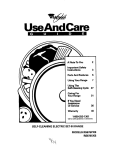
1. Filter
2. Heater
Re.t
Li~t
3. Hi-Limit
Reset
4. Spa Light
5. Heater
8. Push-PuII Gate Valve
7. Air Control
Knob
,
,
ID 11 12
\
,
I
\
.,
13 14 15 18 11 II
II
21
8. Control Panel
9. M81:Ntie Door Interlock
10. Power Supply Cord (120V .20A)
11. Dfainage Hose Bib
12. Ground Lug
13. Power Box
14. 20A Systel" Breaker
3
when
Aesthetics -Select
a location that
enhances the overall environment of
your home.
a.
3 4
-.,
INSTRUcTIONS
;1
I
,
21
15. G.F.C.I.
16. Power Light
17. Pump
18. Magnetic Door Interlock
19. Control Enclosure
20.
-- Time CI6ek
21. Air Blower
b.
c.
d.
,ccccc,--c-2.2.1 120 VOlT SYSTEM
120 Volt wired Portable Spas come with
a 120 volt power cord. This cord contains
heavy duty No.12 wire and is designed to be
the ON L y cord connection between the spa
and the power supply. NEVER use an extension cord to bring power to the sPa.-Extension
cords create resistance and will caUE the spa
equ ipment to operate on too low levels of
voltage. This lower voltage will cause major
damage to the electrical components in the
spa and may void the warranty.
local codes -check
local codes pertaining to fences, gates ai\d electric prior
to location of your spa.
Privacy and Wind Shielding -A sheltered
environment with less wind and weather
exposure can resuIt in lowered operation
and maintenance costs. Also consider
view or non-view from the house,
proximity to change area and a pathway
to and from you r spa clear of debris and
dirt so as not to track them into the spa.
Spa Maintenance -Consider
the spa
closeness to trees and shrubbery; leaves
and birds could cfeate extra work in
keeping your spa elean.
Use the supplied power cord to meaSJre the
distance to your electrical outlet If the cord
will not reaeh~ you muSt either move the spa
or have an electrician run a dedi~ted 120
volt, 20 ampere service to an ~ptable
proximity of the spa.
.
2.2 ELECTRICAL SERVICE
Spas
equipped with LX or OX series
equipment skid.packs can be installed with
120 or 240 volts. Note that 240 volt
inStallation affects heater utilimion
only.
Wired 120 volts. the heater draws 1.5 KW.
Connected with 240 volts. the heater draws
6.0 KW. All remaining electrical components
COntinue to operate on 120 volts protocted
by the 20- amperes syStem reset. (SEE SECTION 1.3.4).
Please check your power outlet before inStalling the spa. This~outlet must have a minimum
of 120 volts and 20 amperes. In addition this
pOWer ret.-eptacle muS! be a aeaieated ~fvice,
meaning that no other outlets, appliiiiees or
devices can share the .me circuit. Other
appliances rOb tne circuit of the amperage
neceS$aryfor the 5J>ato operate properly. Also
check that the circuit is properly grounded
and that the receptacle is properly OOnfi9tJred
to accept the pOwer plug. {SEE SECTION
1.3.1 ). In IC)meareas, a ground faUlt interrupter
may be required affnerecept8ble. Check yourlocal building codes. If you have any doubts,
nave your circuit checked by a qualified and
lic-ensed electriCian. Onee the electrical
inspeetlon nas been coii'ipletea a~ any deficiency Corrected, you are ready to move on to
section 3.1 "Getting your spa rudy to u~".
In addition, your
Spa
has tfle unique
design flexibility to be conveFted to either a
240. V, 30 A syStem or a 240 V, 50 A syStem.
The basic differenceS be~een
tfle tflree
electrical ~Stems are in the heater utilizitiori.
They are outlined as follows:
Supply Voltage
Supply Amerage
Heater -KW
Pump Low Speed
Pump Jet (High) Speed
Air Blower
Jet and Air Blower
2.2.2 240 VOlT SYSTEM
YOUf
Spa lX or DX serieS is deSigned to
be easily Converted from 120 volts to 240
volts. Please review section 2.2.
-ON
-ON
-ON
-ON
REATER CONVERStON FROM 120 TO 240
VOl TS REQUIRES
SPECIFIC WIRING
CHANGES THAT ~~N ~~ -~~ERf()RMEI)
ONL V By YOUR DEALeR OR LICENSED
ELECTRICIAN.
All three syStems perform very well. System
selection depends upon personal preference,
household amperage availability and geographic location.
The following iRstfuetion5 are to be given to a
licensed electrician for his use to run a 240
volt hard conduit service to your ~a:
Note that although connecting any of the three
systems is easy, there are very important differences in how each one is done. PLEASE,
FOLLOW INSTRUCTIONS
CAREFULLY.
USE A QUALIFIED AND LICENSED ELECTRICIAN FOR 240 VOLT INSTALLATION.
1.
4
A DUAL
COMMON
TRIP
(not two
single) 30 or 50 amperes circuit br-ker
must be installed
at the household
circuit bOx, depending upon the heater
2.
3.
utilization
mode you Have selected.
This .rvice must be dedicated ar'td used
only to power your spa.
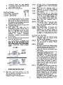
Four wire$ are to be pulled:
STEP 1.
STEP 2.
SYSTEM
Dual Circuit Breaker
2 Line voltage -Wire size No.
1 Ground -Wire Size No.
1 Neutral -Wire size No.
4.
5.
6.
7.
JOA
10
10
12
STEP 3.
50A
8
8
12
STEP 4,
In no case should smaller than 10 gauge
wire for 30A system or 8 gauge wire for
SOA system be used and only then when
the distance from the breaker box to the
equipment is less than 50 feet.
The power box is set-up to receive 314..
coOOuit and fittings.
Open power bOx. Make four wire
connections to power terminal strip as
per the inStructions on the box cover.
(SEE ILL BELOW) Make conversion
wiring changes as per the instructions
outlined
in
..Heater
Conversion
Instruction.', located in the back pocket
of this manual.
Ground equipment to a permanent earth
ground per applicable code.
STEP 5.
STEP 6.
STEP 1.
STEP 8.
ALL ELECTRICAL
CONNECTION
MUST BE TO NEC (NATIONAL ELecTRIC CODE) AND TO ANY PERTINENT
LOCAL ELECTRIC
CODE STANDARDS.
I LL.
12OV -1M
NO.4
ELECTRICAL
SERVICE:
-8»tZ
I
L-.
ZOA.12OV
N8Itr8
~
011-
0,...
12/3
F*
C.-
~-A1A-..Z
ELECTRICAL
SERVICE:
.100..
.'2
DUAL
OPERATING
3.1
mA
8RUKIR
INSTRUCTIONS
GeTTING
YOUR SPA READY TO USE
With all electrical connections done you are
now ready to fill-up your Spa.
Pleese go through the following steps:
5
DO NOT PLUG in 120 volt PQWef'CQrd.
For -2.-40VAC system, make ~re breakers
are OFF.
Make aJre ALL electrical power to
equipment
is in the OFF positioli.
Make sure thermostat is rotated to the
OFF position.
Make 9.lre the two 1~'. gate vaives
located at the Pump inlet and the heater
outlet are in the OPEN position. Lift
up on T handle. MAKE SURE ALL
JETS ARE OPEN (counter-clock wise}.
Make sure drain (hose-bib) valve Is
tight Iy closed.
Using garden hose, fill ~a with water
to 4" of top of spa -DO NOT permit
water line to drop below 5" from top
of spa at anytime.
Wait approximately
15 minutes and:
Inspect ~a
water connections and
perimeter for any leaks or puddles of
water. If there are any leaks, call service
for repair If the leak cannot be readily
corrected, i.e.: connections, unions, etc.
3.2 STARTING YOUR SPA
STEP 1. Plug power cord into 120 volt power
receptacle. Make sure breaker is ON
for 120 v or 240 v systems.
STEP 2. Press "T" test bUtton on GFCI and then
"R" r~t
buttdn to operate. Reoiiew
section 1.3.2.
STEP 3. ox SERIES:
.Set timer for current time. select running
time and set timet selector switcfi t6 ON
position as explained in section 3.3.3.
.Close
door. Spa will not function if the
door is open.
.Push selection button to function #1, low
speed pump. (See Section 3.3.1 )
LX SERIES: Press SYS button (SEE
SECTION 3.4 ..LX Feature and Functions"). Light will come on. Press jet but~
ton. let jet operate for one minute minimum. When the jets are noted to have
steady stream the system is ready. If
there is no jet flow after one minute, turn
system off and repeat start-up proce.
dure. (SECTION 3.2).
STEP 4. OX SERIES: You have just put the timer
selector switch to ON position. Low
speed pump will remain constantly on .
Set thermostat to desired setting. (See
section 3.3.2) Once spa has reached the
desired temperature, set timer selector
switch to center position for automatic
timer control. (See section 3.3.3)
LX SERIES: Press SYS button off .Turn
thermostat counter clockwise to desired
setting. Your spa will start to heat.
STEP 5. .Cover
your spa and it will maintain
pre-set
temperature
continuously,
hours a day.
3.3.2 THERMOSTAT SETTING
The thermostat is located on left side Qf the
control Panel. Turn thermostat clockwise to
desired setting. We recommend starting at
314 of knob rotation. Heater will turn on, and
the spa will begin to heat. Heat indicator light
located on Therapy Control Panel on when
heater is on. (See Section 3.2 Step 4, 5 for
initial heat up time.)
the
24
Initial heat up time will will vary depending on whether spa is configured 120 or
240 volts. Spas with covers will heat as
follows:
120 Volt spas heat 2° -3°
per hour with
cover.
240 Volt spas heat 5° -8°
per hour with
cover.
STEP 6. Add spa water chemicals. (See Spa
Maintenance.).
3.3
FEATURES AND FUNCTIONS
RIES
3.3.1
FOUR
-DX
Check water temperature with a thermometer and adjust thermostat to desired temperature. Once you find the temperature you
like best, identify its location on the panel.
The heater will turn on and off maintaining
the desired temperature during programmed
time.
SE-
FREEZE PROTECTION:
Freeze protection is provided by setting the
thermostat at an adequate temperature
level. IMPORTANT: Time Selector Switch
must be set"QN" to provide freezer protection
(See Section 3:3.3).
FUNCTION
AIR SWITCH
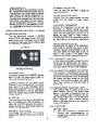
THERAPY CONTROL PANEL
3.3.3
DX Series spas are equipped with a Therapy
Control Panel as shown above. Each depression of the Selection button ehanges the operation of the equipment in the following sequence:
1. Low Speed Pump: READY indieator
light is ON if pump low speed is on and
the heater is OFF. HEAT indicator light is
ON if heater is ON.
2. High Speed Pump (JET) and Blower:
JET and BLOWER indicator lights are
ON. On 220V installation only. HEAT indicator light is on when the heater is on.
3. High Speed Pump (JET): JET indicator
is ON. On 220V installation only. HEAT
indicator light is on when the heater is on.
4. Blower only: BLOWER indicator light is
ON.
ClOCK
The timer controls the pump low speed
ONL v: ALL OTHER spa functions are acces-sible regarding of timer selector switch position, and regardless of timer being on or off.
TIMER SELECTION SWITCH
OFF POSITION (UP): Low speed pump is
permanently off.
TIMER CONTROL POSITION (CENTER):
Timer will start and stop pump low speed as
selected.
ON POSITION (DOWN): Low speed pump is
permanently ON. This position is used to initially heat the spa. or if the spa is going to be
used on several occasions during an entire
day.
Function 1 is controlled by the timer and the
timer selector switch. (See section 3.3.3)
Functions 2, 3 and 4 can be accessed directly by depressing the Selection switch.
These functions are NOT affected by the
timer operation.
LIGHT button turns the light ON and OFF.
ALWAYS sequence back the equipment to
function 1 after spa use. The timer will turn
the pump on and off at selected times. The
heater will maintain the desired water temperature while the pump low speed is on.
TIME
6
SETTING TIMER
a. Turn dial clockwise to set current time
(AM or PM) by lining up the time indicator
arrow and the current corresponding time
on the dial.
b. Each pin represents 15 minutes. Push pin
toward center of dial to set desired running time.
TIMER OPERATION
ALWAYS sequence your spa back to function
No.1 (heater-low speed pump) after spa use.
Program timer 3 to 4 hours daily to maintain
water flltratiQn and desired temperature. Set
timer to come for one hour before and one
hour after your intended use, plus two additional hours. For instance, in you intend to
use your spa between 6 and 8 p.m., set timer
between 5 and 6 p.m. and between 9 and 10
p.m. Additionally. set timer for one hour at 9
a.m. and 2 p.m.
3.4 FEATURES AND FUNCTIONS -LX
ACCESSORY #2 BUTTON:
Turns the light ON and OFF. It does hot
interact with heater .
SYSTEM INDICATOR LIGHT
Indicates that the system button has been
pushed and the system is under manual
control.
ELECTRONIC THERMOsTAT
Controls the temperature of the spa. Set
thermostat
to desired setting and water
temperature and filtration will be maintained.
Heater and low speed pump will. turn on as
needed on both 12Ov or 240\1 systems.
FREEZE PROTECTION is provided by setting
the thermostat at an adequate temperature
level.
SERIES
3.4.1 SPA SIDE CONTROL
The spa side panel includes 4 ON/OFF
buttons: SVS (low speed pump), JET (high
speed pump), Acc #1 (blower). Acc .2 (light),
an electronic thermostat and 2 indicator lights
for SYSTEM and HEA TE R.
f'lEATER INDICATOR LIGHT
Indicates wtiefl me heater is ON regardless of
pump mode or whether the pump is being
operated manually, theJ'moSt8ticall'y or by the
time clock. When the heater light is ON. the
heater is ON, except if the Heater Reset
Indicator Light is OFF. (See Section 3.4.4.)
I L L. NO.6
-
3.4.2 TIME DELAY FUNCTION
A time delay is provided to keep the pump
running for 25 seconds after the heater is
turned OF F. This allows the heater element to
cool down before the water flow is StOpped.
SPA SIDE CONTROL
3.4.3 AUTOMATIC EQUIPMENT PROTECTION
This function is electronically built-in and
automatically turns Off all manually activated
equipment inctuding the "SVS" funCtion after
the system has been turned on for 30-45
minutes. This function protects your equipment from running too long and saves on
electric bills.
SYSTEM BUTTON :
This button controls all 4 ON/OFF buttons.
When it is off. the system light is OFF and
none of the buttons will work.
It directly controls the low speed pump.
Whenever it is on, the pump will run continuously, even if it is in the thermostat control
mode until turned OFF by the "-Automatic
Equipment Protection" function. (See Section
3.4.3) The System always resets off following
a power outage.
3.4.4 HEATER RESET INDICATOR LIGHT
This if1dieator light is located on top of the
heater housing, next to the Heater ReSet
Button. It is used in conjunction with the
"Heater IMieator Light" loCated on the Spa
Side Control (See 3.4.1) to trouble Sttoot
heater operation.
{See Trouble Shooting
Guide in the back pocket of this manual for
further information.)
JET BUTTON:
Turns the pump from low to high speed and
back. For systems with 120 volt heaters, the
heater will turn OFF whenever this button is
pushed. On 240 volt -50A heated system, the
heater will not be affected.
3.4.5
TIME
CLOCK
SETTING TIMER
a.
Turn dial clockwise
to correct
time.
Turning
dial
counterclockwise
wilt
damage timer switching mechanism and
void warranty.
ACCESSORY #1 BUTTON;
Turns blower ON and OFF. This function
interacts with heater the same way as the Jet
button.
7
b.
cAuTION:
---"
---" a.6SiNG
coMPi.ETEi.
y MoRE
.-.,
~,
THAN TWO JETS AT A TIME WILl RESTRICT
YOuR sPA wATeR FLOW AND MAY~CAUSE
THE HEATER AND PUMP TO OVERHEAT.
Each switch activator represents 15
minutes. Push switch activator toward
center of dial to set desired running time.
TIMER OPERATION
"
The timer controls the pump low speed. Its
sole function is to provide added filtration
when needed. The thermostatically controlled
water temperature is not affected by the
timer. When the timer is ON, the pump low
speed comes on, as well as the heater if
needed. When the timer isOFF, the pump low
speed and heater still turn ON and OFF to
maintain the water at the desired temperature.
The timer provides only filtration time if
the thermostat is turned all they way down.
Two air control knobs located next to your spa
control panel control the amount of air intake
Into the jets. Jet pressure is at maximum level
when air knob~ are open. O~e turn is-all that is
ij~~ess~
tQ'",,-I!y-~~n- !5e-8!r- ~nti'Ol~: ~~
need to overtighten when closing. One air
knob
controls the
all divertajet.
regular jets. The second
knob regulates
.
BLOWER
Your spa is equipped with the most efficient air
injection system in the industry. Individual air
injectors are strategically located to provide
maximum therapy. When the blower is on, the
injector cap unique "Shower Head" design
creates thousands of tiny air bubbles. These
bubbles burst through the warm water following your body contour and providing you with
an overall sOOth;~ ana relaxing massage.
The "SYS" button electronically overrides the
timer. JuS! puSh "SYS", then " JET" or
"BLOWER"
buttons to enjoy your spa.
ILL. NO.7
.~«.-"
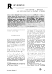
SPA MAINTENANCE
4.1 GENERAL MAINTENANCE
4.1.1 EQUIPMENT
Is located under the wood skirt. The G.F.C.I.
should be tested before u~ of your spa. Any
other servicing should be done by your dealer
or other authorized peroonnel.
.
""p.~.'
"..~
4.1.2 COVER
Is an optional item for use with your spa, but
is essential for proper temperature control and
efficient operation. We strongly r~mmend
to use a cover.
TIME CLOCK LX
3.5
JET
ACTION
JETS.
Spas are provided with 3 types of therapy jets.
ADJUSTABLE JETS. 3 to 5 per spa can be
adjusted by turning the entire face of the jet
counterclockwise to open and clockwise to
close. The water stream is directional and
massages one point of the body.
MINI~SAGE JETS, 2 to 3 per spa are not ad~
justable. Water stream has a swirling action
which covers a 12.. area of the body.
DIVERTAJETS, 1 to 2 per spa open clockwise
and close counterclockwise by turning the entire face of the jet. When on, divertajets channel 100% of the pump output, creating a whirlpOOl! turbo action which in turn provides a
motion massage on your entire body or part of
it, depending on how close to the jet stream
you choose to be.
4.1.3 CLEANING YOUR SPA
U~ a liquid cleaner that contains no abrasives,
e.g., 409, Fantastic, Spa Gloss -DO NOT use
a cleanser or hard brushes.
4.1.4. WINTERIZING
In areas
of
the
country
Q
where
the
temperature
goes below 32 I follow these steps.
STEP 1. If the spa is not to be used, drain
completely
and store in garage if
possible. (See 4.1.5)
STEP 2. If you are going to u~ the spa, keep
$pa warm on thermostat contrOl. DO
NOT TURN UNIT OFF or frozen
water
may
burst
plumbing.
(See
SectiQ" 3.3.2 "Freeze prQtection" and
3.4.1)
Jets are located at proper heights to provide
soothing massage on various parts of your
body. Adjust jets as needed, but never close
them completely.
4.1.5 DRAINING YOUR SPA
STEP 1. Unplug the spa.
8
~-rr~r
i\lt;I(:11
'J;jl\lt~11
IIO5H
to
IIIIJ..I
i I,t:
i illl;1
I, JI..,t,.,1
\"Iii
l'II'I'ly
!.,I!,i'i'
,
yl'llr
.,.'",1
IJV
;jl
If
I:I~
110Se
Spa
~;lfJIIOII
VIlli
nr\;
v'Jirll\~r,
!10
temperature ac(:elt~rates the release of body oils
;Ind ~Irease into tl)e water. Water flow through
tllc filter causes susrJended particles and oils to
ber;onlf:. triil1ped on ils fine polyester mesh
surfa(:c. 13ODY OILS cAr\JNoT BE WASHED
ofr
\'1!I-rl-l r'\ GARDEN HOSE. OILS MUST
BE DISSOL Vl:D. This is easily done by lifting
tile cartrid~le out of the housing and soaking it
ov(~rniqllt il)to a 5-Ijallon pail of water with 1
cup of (lisl)wasllcr
detergent
(Cascade for
instance). The cartridge must then be rinsed
TI--IOROUGI-IL Y and left to dry before using
it again. A SIJare standby cartridge is an
excellent investlnent. It provides convenience
and assures that your filter will always be
ready to operate at peak efficiency.
hilJ
Ij()llsirl!l.
~Irilvlt\i.
~V,i!\::r.
I\JI
y(~IIOW
out
Jr(lining
l()
SlCI)~
3
!
I!
1!\llil
'
;
I. '
1
.
",
"
II
'1111 ..
~;
IliIJ(;
Ilrliull:;
illl(1
on
tIll'
I!\i'
tij ,(,
1IIIIlII)
rUll1r)
i,;
ovl:r
tJ I'UMP
pnIMIN(;/WI\TEr~
IJlimll
f~ssef1tirtl
(l)rrf)r::Lly
I()ft.
tllat
heart
the
10 [Jrl:VCI-It
-rh(~lefore,
illltl
rtllll['
IlrIIJ(JI\;IIII,
l:.lll111)
ill i)
l.I\,l:;II'I(;II:'t;J
I)y
i.ll LIIP irllel
prl"Vents
the rJIIOlp
hei;lter.
url!
Tl1is
yollr
pump
rlliiirrtain
I)OI'kl!tS
of
and
be
the
tile
from
of
whicll
111~;IIPr lissl~rnbly.
Tllese
air
in turn
water
can
is
cavitations
1orl11dtion
pllshinIJ
your
prime
prime
or
condition
folll)('lj
to
to
rump
puinr
HOW OI=TEN: Frequency of filter cleaning
depends upon water chem istry .spa u sage and
spa location.
Every 3 to 4 weeks may be
sufficient.
f-Iowever. your cartridge needs to
be cleaned if the water level in the center of
the cartrid~Je drops substantially in pump high
speed. A clogged (:art ridge will cause air suction through the center of the cartridge and
will cause the pump to cavitate. (See Section
it
operated
how
l)rill1irl!J
the
uf
spa and
(jumage
knowing
yOtIr
or
R('!-illstall
inlioors
suriolls
Ijijr',
I)tlrlll)
sure
LEVEL
is tile
(~(l!JipOI~rlt.
tile
by
1'v1iJkc
tile spa.
1.11!' wi1t!;r
is
line
suction
rUlllrJ
rlhl\J
i ,IIIII)I["J
.il! ii llllIUIl';.
:IO!tJ
I iltcr
cartrilJ~Jt
p
ltiscon-
rt:tllrn
'JV:lrt'!
IIi!!
rl',I, 1111i \;.ttl:r
(J
I)V
011 llle
through
rlama<Je
c:ir
4.1.6)
the
pockets
Ij'/:
Tral1l1C(j (lir ulJrirl!J initial filling.
Refer to
I)rinlinu
in~;trllctions.
{Section
3.2)
~)I)a water
level (Jrol1pinrJ too low. It is
:1
throllUh
the centl-.r
of thc filtf!r
MainterIJrlCe"
curtrill~Je.
Sf:!ction
or li1ck of pllmp prime.
THESE
CONDITIONS
':.:ORRECT[[)
FILTER
Every
efficient
IMMI:DII\Tr=L
"Sputters"
cavitation
MUST
top
loadin\1
-Vs- FI L TRATION
BE
v.
skimmer/filter
A WELL
MAINTAINED
'r'oU
MAINTAIN
yoUr{
considcr
chemical
have to consider
most
system
in
srlry
f()()t (:ilrlri(I(J(~ filll'rs
both l)i~Jh and low
to
rcmovc
FILTER
HELPS
SPA:
Berore
you
treatment
your filter.
particles
of
of your spa, you
Filters are necesoust,
dirt,
alqae,
body oils, etc. that are continously
entering
the wuter.
If your filter
doesn't
operate
corrr'r.llv.
fIr \f111fl r'1101If\11 (;It Ir';I'it1hOlIr'irl;lily)
UI Isii'l lllCIlllti.lllled
IJruIJerly,
tllen Il C(lllnul
remove
lhesc wustes from
your
spa. These
speed functions.
F i Iter maintenance
in keeping
your
TREATMENT
The pleasure you derive from your spa is
directly
related to the quality of the wa,ter
you have in it. There are two primary factors
to consider in maintaining
your spa and the
quality of the water in it: one is chemical
treatment, the other is proper filtration.
Both
are iml)Ortant.
(See I'Filter.
CAr~TRIDGE
MI\IN1-ENI\NCE
Vita
Spa is desi!Jne(1 with
the
III(! if)(Juslry. I\ ~jO ';(I'lilr(~
1000;;, of the water un(jer
also
the
4.2)
No water jet (](~tion or jet stream
with
a "crackling"
noise indicate
4.3.1 CHEMICAL
NEVER USE ACID OR TRI-CHLOR
THEY
RUIN ACRYLIC SPA FINI$H. If the PH level
gets too high, simply empty the water and
refill with fresh water.
filter
cartriufJc.
Clo~I~Jl:il rill(~r
-Tllis
conuition
will
CijU51: tllf:! I)UmIJ to slJck uir through
centcr
4.2
of the
MAINTENANCE
WARNING!
es~;I..nti;il th(lt wuter
level he maintained
il1 ;11)OIJt ,1" from illl~ tO~) of the sl1a. A
low wfltlJr I(:vcl will cause the l1uml1 to
sLIck uir
4.3 SPA WATER
is the most critical factor
spa water
clean.
High
9
7
extra wastes put a burden on your chemicals
causing exta expense you d'on't need.
Depending on spa usa~fe. clean your filler
evcry 4 weeks. (SeIJ Set:lioll 4.2) Cilallye your
sll.lw.ltl.rl.V(.lyHlIll0wl!l'ks.
KNOW THE AMOUNT
OF WA-rER
SPA: Refcr lu yuur Vila SpalJruclIure
Read tests within
10 seconds
after
all test
solu tions are added.
Make color comrarisons
ill dayli(Jht.
not
urluer
ilrtifit;ial
liyllt.
Colors are eiJsiest
r!!iJd i,l tllc sh(J(j!!, facil)fJ away frorn the
8.
liullt SOllrc!!, rcadillq
a Wllitc lJack~lroulId.
IN yoUr{
fur spa
thf~ test lJlock
agiJinst
gallonage.
Store thc test I(it uWily rrol11 SUllli411t ull{1 hc"t.
Insure
that test solutions
are fresh;
rCIJlace
ALWAYS TEST THE WATER: Testing is the
only way to make sure the water is safe and
comfortable.
Tap water that's safe to drink
may not be right for your spa. Mineral and
metal imbalances can shorten the life of your
Sl1a and equ ipment. I t is iml1OltDl1l llJDt you
have an accurate test kit for chlorine and/or
bromine, pH and total alkalinity.
One that
also tests for calcium hardness is even more
regularly.
Arlotller
Si~Jiliric(Jnt fll(;tor is tile ratio of
bather load to gallonage amJ the amount of
contaminants
put into the water from each
bl1t1lcr. Sevcrl11 Clr!llr l1(JVlJlltll!I(!S in tlJe sJ)a
disinfection
arise from the use of hrominc
when compared to tllc stlJrl(Jard techniques of
chlorine trea trllent.
1.
Disinfection
efficierlcy
with bromirle is
not signific(Jrltly rH ueperldellt in the pI;
range of 7.0 to 8.0.
2.
Bactericidal
and viricidal
efficency
of
bromine is not reduced by the presellCe
of ammonia and/or orgarlic amines (i.e.,
perspiration, urine}.
3.
Eye irritatiorl
alld halogen odors are
minimized by the use of bromine.
4.
When properly stored, bromine is very
stable.
helpful.
Make these tests daily until user load is established,
and then several times weekly
to be
\
sure proper levels are maintained.
The
regular
I
use of your test kit will avoid costly guesswork
and alert
you
to serious
problems
before
they
develop.
4.3.2
HOW TO TEST THE WATER: Water testing is
done by filling the test kit with a sample of
spa water, adding drops of test solutions, and
noticing color changes.
The accuracy
avoid errors:
2.
3.
4
5.
6.
of chemical
tests is critical.
Following
tIle initial hydrolysis
of urolllill(J,
tllfJ
remaining water chemistry
is IJlIse(J ui)on Hypobromous Acid and Hypochlorous
Aci(J. I-JyIJobromous Acid reacts with ammonia to form a scries of
compounds
called bromamines
which are active
disinfectants.
Hypochlorous
Acid liberateLi frolTl
bromine functions lIS a regenerated form or active
bromine disinfectant
thereby creating additional
free bromine.
To
Run jets (without air} for a few minutes
to mix water in the spa thoroughly
before testing.
Rinse test block with spa water berore
and after each test -never empty test
block into the spa water after a test.
Take w()ter samples toward the center of
the spa, at least twelve inches below the
surface -do not take samples near the
filter return lines.
To obtain
proper size, hold the test
solution
bottles
vertically
add drops
To
sanitize
mine
water
always
maintaill
a collstalll
activu
or chlorine
residual
of 2 to 4 pplll.
clear,
"shock " wilh
clllorine
to
inactive
is the
ammonia
facturer
bromine
most
back
cost
in water.
instructions
to the ( HoUr)
efficient
method
form.
of
uro-
To l.<eelJ
ruisc the
Clllorine
oxidizing
Follow
your
chemical
Inanufor proper
c'lcmical
usu arId
dosage.
4.3.3 pH CONTROL:
pH can be described as a measure of tllC acid
activity
in water. It is important
because it
dictates the perccnta!jc of trlJly uscful S,lllitizer
that can be expected.
slowly.
Do not perform other tests when the free
chlorine/bromine
level is above average conduct tests only when level drops almost every test kit will bleach out and
not give accurate readings.
Do not use fingers to cover the larger
test cell; as chemicals on skin can affect
resu Its.
The overall importance of IJH control is often
underestirnated.
If pH is out of the desirable
range it can adversely affecl: (1) clarily of the
10
,,",
~;':(
water; (2) bactericidal
efficiency
of the sanitizing agent; (3) odor of the water; (4) skin and
eye irritation
to the bather;
of the spa water;
wall and piping
deterioration
(5)
corrosiveness
(6) scale formation
on spa
(7) short
filter
cycles
(8)
of heaters.
The pH scale runs from 0 to 14, with 7.0
being the neutral or mid-point.
any pH less
than 7.0 is on the acid side of the scale: the
closer one comes to a pH of 0.0 the more
corrosive th~ water. Any rH greater than 7.0
is on the bi)sic or alkaline sirle of tIle scale; the
closer one comes to a pH of 14.0 the more
caustic tl)e water. It is generally agreed that a
f)H in the range of 7.4 to 7.8 is the most
comfortable and desirable level.
Adjusting the pl-l can be readily accomplished.
l-he ad(Jition of pl-l litJ. which is sodilJm
(~arbonatc or so(lcJ ash will raise pl-1 rapidly
while raisinl] alkdlinity slowly.
4.3.4 ALKALINITY:
Total ulkalinity,
as opposed to pH, is the
rlllantitative
measllrement
of the alkaline
material,
bicarbonates,
hydroxides,
etc.
rresent in the water which acts as a buffer
against rapid pH chan(]e. Slla water should be
tested regularly to determine the total alkalinity which should be in the ran!le of 90 to 120
ppm. -90 bein~J the ideal. To raise T A, use
SodilJm Bicarbonate
(baking
soda) which
raises the alkalinity
rapidly. It also will raise
the pl-f slowly.
ACID
OR TRI-CHLOR
MUST
NOT
BE
USED. IT WILL RUIN YOUR SPA FINISH.
4.3.5 CALCIUM I-IARDNESS:
Total hardness is made up of pissolved calcium
IJlus smaller quantities of other mi~eral salts
including Inagnesium. It must be noted that
the amour It of calcium hardness present will
vilry from one spa to another and is what
dictates water balance. The higher the calcium
hardness level the lower total, Cjllkalinity;
conversely the higher the TA the ,lower the
cillcium hardness one should maintain. Water
will tend to halance itself hy leaching calcium
frorll WII{lt(~Vl~r is (Iv(Jilable be it pool Wlllls or
your hody. Try to maintain a higher calcium
11ilr(Jn(~ss1(~v~1than the T A --idelJlly it should
be 200 [() 22b I)prn.
4.3.6
WATER
Because
clcvat('(1
CLARITY:
of the
heavy
tcmpcratllrcs,
demar:ld
yollr'
on the water
Sl)a water
at
may
appear to be cloudy. This indicates that your
filter may be fouled and should be cleaned
immediately.
If after cleaning the filter, the
water remains cloudy, check pH and TA. If
cloudiness
still
persists,
introduce
water
clarifier. This J)roduct is formulated to suspend
part iClJlate matter
to form
large enough
particles to be trapped by your filter. Also
you will use less chlorine or bromine because
the water clarifier removes and neutralizes the
particles before the chlorine or bromine has
time to oxidize them.
If frequent
dosages are indicated
water continues to remain cloudy,
need to drain and refill you spa.
and the
you will
4.3.7 FOAMING:
Foaming
is caused by shampoo and soap
residues, hair sprays, cleansers and even "soft"
water -low
total alkalinity
and calcium
hardness. When air is bubbled through water,
surface tension tends to create a film on top
of the water which, in fact, does not allow the
air bubbles to pop. These bubbles begin to
form on the surface and have the appearance
of foam.
In order to reduce the foam, the use of No
Foam
is
recommended.
This
product
immediately
reduces
surface
tension
by
breaking down the oils and removing them
through filtration.
Squirt a small amount of
No Foam across the surface of your spa water.
If you find that it does not accomplish
defoaming
of the water within
one hour,
repeat the dosage. If several applications are
required, this is an indication
that the spa
should be drained and refilled
with fresh
water .
4.3.8 COLORED WATER/SCALE
FORMATION:
Colored water is generally caused by: the
presence of metals such as iron, copper and
manganese. They can be present as metallic
ions in solution or as finely divided particles
of metallic compounds
in suspension. Each
metal imparts its own characteristic
color to
the water when oxidized
by chlorine
or
bromin~. Iron produces a reddish brown tint.
Copper causes the water to appear blue-green
and when manganese is present, the water
takes on a dark brownish black hue.
Because minerals and metals are generally
present ill the fill or make-up water, a proper
chelating agent should be used to hold these
minerals and metals in suspension to prevent
scaling ilnd corrosion.
Corrosion and -=ale formation
result in
decreased heater efficiency
and. if left
~ncheck~, m~y ~use complete ~1~99i~ of
heater lines necessitating expensive replacements of heaters. pipes and metal fittings.
?
.oxidized
9rganic
~n~
by ozone.
inQrg~niG ~taminants
th~n e~jly
separateQ
the3.water
through
filtration
system.
ozone
~ Is the
"most
-friendly"-
to
are
fr9m
the
environment
introduces
~obecause,
forms ~ 91unlike
tP~ic chlorine,
Qr ~reactiveit
4.3.9 ALGAE:
Algae are microscopic plants which can grow
in a spa if the free chlorine or bromine readings drop too low. It can sneak up on you
without you seeing it. Algae spores are always
in the atmosphere and soil. Rain showers,
winds and dust storms are constantly ~umping
these spores into your outside spa. Sunlight
and warm temperatures provide th~ ~Iimate
for algae to reproduce and grow -and grow.
When you can see them you already have
about 30 million algae per ounce of water.
by-products.
4. Ozone, unlike chlorine, leaves no foreign
chemicals remaining in the water.
5. No by-products other than oxygen, carbon
dioxide, and filterable remains are geflerated by
using ozone.
ENJOY
The best way to take care of algae is to never
let it appear. Diligent testing is a great preventative along with the use of an algaecide.
Treatment consists of supercholorination and
an algaecide appli~tion.
4.3.10 ALTERNATIVE DISINFECTION METHODS
The spa industry is unique in that its end
product. the spa, in its most basic definition, is a
vessel which. when filled with water, heated to
the recommended temperature for safe use,
second, then allowing that water t~ move around
a person's
body, creates a pleasurable,
therapeutic environment. Unfortunately, this.
same
water
becomes
saturated
with
contaminants and bacteria.
Primarily, there are three methods of disinfecting
the spa water. The first, and most widely used, is
chlorine disinfection. Atthough powerful and
effective, there are some adverse si~e effects:
strong odor, limited life, strong irritant. very
unstable. The second, bromine, although not as
strong as chlorine, has minimal odor, is more
stable, and is less of an irritant. The third
alternative is ozone. Although it is 50% more
powerful than chlorine and 90% more powerful
than bromine, it has not been as popular as the
first two disinfectants, due to its relatively new
introduction in the market. Howeveri it is fast
becoming
the recommended
method of
disinfection for the following reasons:
1.Disinfection takes place at a much higher
oxidation level. In fact, there are no bacteria or
"Iruses that are resistant to ozone.
12
YOUR
SPA!