1
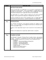
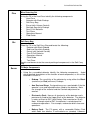
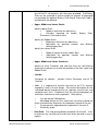
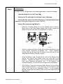
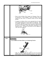
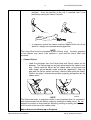
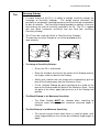
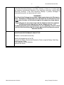
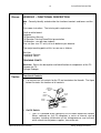
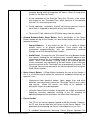
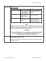
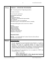
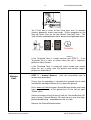
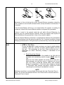
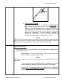
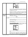
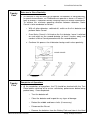
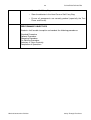
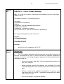
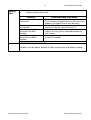
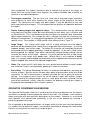
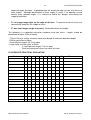
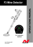
INSTRUCTORS NOTES AND SYLLABUS F3 Metal Mine Detector Issue 1.3 March, 2006 2 F3 INSTRUCTOR NOTES WARNING THIS DOCUMENT CONTAINS MINELAB ELECTRONICS LIMITED RIGHTS TECHNICAL DATA OR RESTRICTED RIGHTS DATA OR BOTH. Minelab Electronics This work is copyright. Apart from any use as permitted under the Copyright Act 1968, no part may be reproduced by any process without written permission from Minelab Electronics 118 Hayward Avenue, Torrensville South Australia.5031 Minelab Countermine Division Safety Through Excellence 3 SLIDE F3 INSTRUCTOR NOTES DESCRIPTION INSTRUCTORS NOTES These Instructor Notes are produced to assist instructors in preparing for the F3 Operator Training Course. They are provided as a guide and are not intended to be prescriptive. They should be used in combination with the information contained in the F3 Operations Manual and Field Guide. The confirmation of a student’s ability to operate the F3 will be achieved through a series of performance objectives completed after each lesson. Personnel attending the course will be required to pass an outdoor operator confirmation exercise to qualify as a proficient operator on the equipment. One INTRODUCTION The instructor will provide a short welcome and brief the students on the course. This can include some background information on Minelab and its countermine product range. Students will be organized into pairs and issued one F3 mine detector per pair. Students will complete course registration administration as required. Two COURSE OUTLINE The Minelab F3 Operator Training Course includes lectures and practical sessions. The course is conducted over two to three days (depending on language translation requirements) and consists of the following lessons: • Introduction • LESSON 1 – General description and preparation • LESSON 2 – Functional description • LESSON 3 – Operating procedures • LESSON 4 – Care & Trouble Shooting • Outdoor training • Operator Confirmation Exercise • Award of Course Certificates Minelab Countermine Division Safety Through Excellence 4 Three F3 INSTRUCTOR NOTES LESSON 1 – GENERAL DESCRIPTION & PREPARATION Aim. Correctly describe and identify the F3 and prepare it for use. Classroom Instruction. The training aids required are: Chalk board or white board Computer Projector F3 Operations Manual F3 Operator Training PowerPoint presentation One F3 inside a Hard Case and one F3 in its soft Carry Bag F3 detectors - one per two students (including Hard Case) The major teaching points of this lesson are as follows: Safety Equipment Specifications Description of Main Components F3 Preparation TEACHING POINTS Three Four Safety. Emphasize the need to become very familiar with the equipment and the need to be able to identify all parts. Relate this to safety issues during the demining process. All components should be checked for correct operation before operating the equipment. If a fault develops, an operator must be able to correctly name the part of the detector that is at fault. Explain the importance of the Test Piece. Equipment Specifications. List the basic specifications. Explain that the entire detector is waterproof to IP67. Explain the need to use good quality alkaline batteries and not carbon batteries. When using rechargeable batteries, they should have a minimum capacity of 3Ah (3,000mAh), batteries with a capacity of 4.5Ah (4,500mAh) are recommended. Minelab Countermine Division Safety Through Excellence 5 Five F3 INSTRUCTOR NOTES Mine Detecting Set Using the F3 in the Hard Case identify the following components: • Hard Case • Detector with Black Endcap • Soft Carry Bag • Earset (with Volume Control) • Red Low Sensitivity Endcap • Four D Cell Batteries • Test Piece • Operations Manual • Field Guide • Six Soft Carry Bag Show the F3 in the Soft Carry Bag and locate the following: • Detector with Black Endcap • Red Low Sensitivity Endcap • Earset (with Volume Control) • Four D Cell Batteries • Operations Manual • Field Guide • Test Piece Explain and demonstrate the correct packing of components in the Soft Carry Bag. Seven F3 Major Components • Using the assembled detector identify the following components. Avoid giving detailed descriptions of the function of each component, as this will be covered in Lesson 3. o Endcap. The sensitivity of the detector by using either the Black (maximum) or Red (minimum) Endcaps. o Arm Rest and Strap. Designed to ensure a comfortable fit for the operator’s arm and adjustable when fitted to the detector. Note the strength of the material and the Camlock adjustment for comfort. o Electronics Pack. Houses all electronics of the detector and is permanently fixed to the Upper Shaft of the detector. The detector is water resistant to IP67 (with Battery Pack mounted on Shaft). Note: Although rated to IP67, the detector is not designed for underwater operations. For example, underwater diver clearance operations. o Battery Pack. The F3 comes with a removable Battery Pack which holds four alkaline ‘D’ cell batteries as standard. However, Minelab Countermine Division Safety Through Excellence 6 F3 INSTRUCTOR NOTES if the client has purchased the option of a Battery Charger then four NiCad ‘D’ cell batteries will have been provided. The Battery Pack can be removed to reduce weight for periods of prolonged use provided the optional Battery Pack Bag & Extension Cable is included with the detector. o Upper, Middle and Lower Shafts. Identify Upper Shaft: • Made of aluminum for robustness. • Provides mounting for handle, Electronics Pack and Armrest. Identify the Middle Shaft: • Made from aluminum for robustness. • Adjustable for operator comfort demining positions. Identify the Lower Shaft: • • Battery Pack, and differing Made of impact resistant carbon fibre Adjustable for operator comfort and demining positions. differing o Upper, Middle and Lower Camlocks. Identify all three Camlocks and note that they are self-cleaning and are the mechanisms to lock the position of the Coil, Lower and Middle Shafts. o Handle. Designed for comfort. Controls. Includes Earset Connector and all F3 o Coil. It is important to mention that part of the F3’s superior capability is due to its coil design. Give a brief description on the monoloop design explaining that no separate transmission and reception coils exist. Emphasize that the closed waterproof coil eliminates interference from vegetation. Other points: • Can be rotated 180 degrees. • Monoloop design ensures consistent sensitivity around the entire circumference and across the complete surface of the coil. • Design permits edge detection (explained in Lesson 3). • Extremely tough. o Skid Plate. The skid plate provides protection for the coil. It has no effect on the sensitivity of the coil even when wet and is easy to replace. Minelab Countermine Division Safety Through Excellence 7 Eight F3 INSTRUCTOR NOTES F3 Preparation To prepare the F3 for operations the following procedure should be followed: • Open the Hard Case or Soft Carry Bag. • Remove the F3 and inspect for obvious signs of damage. • Check that the correct Sensitivity Endcap is selected and mounted correctly. (Changing Endcaps discussed in Slide 10). • Battery Pack and Inserting Batteries o Invert the F3 being careful to rest the Endcap either inside the Hard Case or Soft Carry Bag to keep it clear of dirt, remove the Battery Pack and insert four D Cell batteries as follows: Battery Pack Battery Lock Lever Battery Map Battery Pack Lid P0615-A o Carefully unlock the Battery Pack Lid by rotating the Battery Lock Lever counter clockwise one-quarter turn. Once unlocked, carefully pull the lid away from the Battery Pack (the lid will stay attached to the Battery Pack by a tether). o Using the battery maps, located on the side of the Battery Pack and on the inside of the Battery Pack Lid, insert four D cell batteries. Replace the Battery Pack Lid and rotate the Battery Lock Lever clockwise one-quarter turn. If the batteries are inserted incorrectly, the F3 will fail to function when switched on. o If the Battery Pack was removed (Note: removal of the Battery Pack to replace batteries is not necessary) ensure that the Lock Lever at the front of the Electronics Pack is in the unlocked position and position the Battery Pack on the rail underneath the Upper Shaft. Minelab Countermine Division Safety Through Excellence 8 F3 INSTRUCTOR NOTES Upper Shaft Battery Pack Electronics Pack Lock Lever P0616-A o Slowly slide the Battery Pack towards the Electronics Pack until the connector is firmly engaged. Secure the Battery Pack by rotating the Lock Lever in a clockwise motion into the locked position. o If required, the Battery Pack can be separated from the Upper Shaft thereby reducing the overall weight of the detector. Using the bayonet connectors at each end of the Extension Cable connect the cable to the Battery Pack and feed the cable through the base of the Battery Pack Bag before connecting to the Electronics Pack. The Battery Pack Bag can then be clipped onto a belt worn by the operator. P0653-A Nine F3 Preparation • Extend Middle and Lower Shafts to suit demining Position Middle Camlock Upper Camlock Lower Camlock P0617-A o Open the Lower Camlock and rotate the coil to the desired position. The normal operating position of the coil is in line with the shaft. However, the coil can also be positioned at right angles to Minelab Countermine Division Safety Through Excellence 9 F3 INSTRUCTOR NOTES either side of the shaft (required if the F3 is to be used in the prone position). Once the position of the coil is selected, lock it into position by closing the Lower Camlock. P0618-A P0619-A P0620-A o In sequence, extend the Lower and then Middle Shafts to suit the deminer’s height and selected demining position. NOTE The Lower Shaft must be extended at least 100mm (4ins). Incorrect operation of the detector may result if the detector is used with the Lower Shaft fully retracted. • Connect Earset o Undo the dustcaps from the Earset plug and Earset socket on the detector. The Earset plug can only be connected to the socket in one way. Gently hold the Earset by the rubber collar using thumb and index finger (raised double arrow should be uppermost). Align the plug with the Earset socket and firmly slide the collar onto the socket. Confirm the plug is locked into position by gently pulling back on the rubber collar. P0638-B NOTE The Earset connector is waterproof and it is most important that it is connected and disconnected from the Earset socket by holding the rubber collar. Do not attempt to connect or disconnect the Earset by pushing or pulling on the strain relief or wire at the rear of the rubber collar. Adjust Armrest and Armstrap as Required. Minelab Countermine Division Safety Through Excellence 10 Ten F3 INSTRUCTOR NOTES Changing Endcaps • A unique feature of the F3 is its ability to change sensitivity through the exchange of Sensitivity Endcaps. This design feature eliminates the possibility of an operator selecting the wrong sensitivity through manipulation of dials or switches. The Sensitivity Endcap provides an obvious visual cue that confirms the level of sensitivity selected in the F3. The F3 is supplied with one Black (maximum sensitivity) and one Red (low sensitivity) Sensitivity Endcap. • The F3 can be used with Black or Red Sensitivity Endcaps. The decision on which Endcap to use will be provided by the local authority. P0650-A • P0651-A To change a Sensitivity Endcap: o Ensure the F3 is switched off. o Place the thumb of one hand in the centre of the Endcap and curl the fingers under the base of the Endcap. o Gently push inwards with the thumb and simultaneously pull the base of the Endcap away from the Electronics Pack. o Fit the selected Endcap by gently positioning the inside of the base of the Endcap under the base of the Electronics Pack. Using the palm of the hand, apply light pressure to fit the Endcap into position. • The Black Endcap is for Maximum Sensitivity. o The Black Endcap MUST be selected when searching for minimum metal mines or when maximum clearance depth is required. • The Red Endcap is for Minimum Sensitivity. o This feature may be useful when there is a need to ignore small metal fragmentation on the surface but still detect large targets at depth. Minelab Countermine Division Safety Through Excellence 11 F3 INSTRUCTOR NOTES NOTE If the Red Sensitivity Endcap is not fitted correctly, or there is no endcap fitted, the detector automatically defaults to the maximum sensitivity setting (Black Sensitivity Endcap). If the Red Sensitivity Endcap is partially dislodged or removed during use, an alarm tone will sound. **WARNING** The Sensitivity Endcap also provides impact protection to the Electronics Pack. Whenever an Endcap has been removed from the Electronics Pack never place the base of the detector against the ground or sharp objects. Depending on the size of the target and the depth of detection required, the Red Sensitivity Endcap may not be suitable for use. It is recommended that, prior to operational use, the capability of the F3, fitted with the Red Sensitivity Cap, be tested against the local threat to ensure detection occurs. QUESTIONS/PERFORMANCE OBJECTIVE Students shall be able to correctly: identify all components of the F3. connect the Battery Pack to the Electronics Pack using the Battery Pack Bag and Extension Cable insert batteries into the detector connect the Earset Minelab Countermine Division Safety Through Excellence 12 Eleven F3 INSTRUCTOR NOTES LESSON 2 – FUNCTIONAL DESCRIPTION Aim. Correctly identify and describe the functional controls and tones and the F3. Classroom instruction. The training aids required are: Chalk or white board Projector F3 Operations Manual F3 Operator Training PowerPoint presentation F3 detectors - one per two students One set (four size “D” cells) of fresh batteries per detector The major teaching points of this lesson are as follows: Revision Functional Controls Functional Tones TEACHING POINTS Revision. Revise the description and identification of components of the F3. Prepare the F3 Change Endcaps Twelve Functional Controls • For ease of use, all controls for the F3 are located on the Handle. The figure below illustrates the location of all controls: Ground Balance/ Audio Reset Button Noise Cancel Button On/Off Switch Earset Socket P0621-A • On/Off Switch. o The F3 is switched on by sliding the On/Off Switch toward the Handle. When switched on, the F3 completes a series of internal start-up functions including initialization of the microprocessor and self-tests which check internal power supplies, transmitter etc. Minelab Countermine Division Safety Through Excellence 13 F3 INSTRUCTOR NOTES o These internal diagnostics take approximately 12 seconds to complete during which the operator will hear a series of rising tones (known as the Start-Up Tones). o At the completion of the Start-Up Tones the F3 emits a low steady tone known as the Threshold Tone, which confirms to the operator that the F3 is functioning correctly. o During operation, continuous internal self-testing continues and an alarm tone is triggered on detection of any fault condition o To turn the F3 off, slide the On/Off Switch away from the Handle. • Ground Balance/Audio Reset Button. Easily identifiable as the Green Button located on top of the Handle, this dual action button carries out the following functions: o Ground Balance. A key feature of the F3 is its ability to detect metallic mines in all ground conditions. False alarms due to mineralised (magnetic/lateritic) soils are automatically removed through use of the Ground Balance function. o Audio Reset. On occasion, the Threshold Tone may become louder than normal. Holding the coil stationary over a metallic object or over mineralised ground for an extended period of time may cause this effect. Also, if the detector is being used in the kneeling position (shafts retracted), any movement of the coil relative to the shaft may cause the volume of the Threshold Tone to dramatically increase. The Threshold Tone can be returned to the normal volume level using the Audio Reset function. • Noise Cancel Button. A Black Button located to the rear of the Handle, it sits in a raised housing to reduce the chances of accidental contact by the operator’s arm. o Interference from electrical motors, lights, power lines and other detectors can occasionally cause the Threshold Tone to vary in pitch and volume. When this occurs, the ability of an operator to distinguish targets may be degraded. o Using the Noise Cancel function, an operator can initiate an automatic frequency scanning sequence resulting in the F3 selecting an operating frequency that minimizes the effect from interference. • Earset Socket. o The F3 has an internal speaker located inside the Handle. However, the F3 can also be fitted with an Earset via the Earset Socket. The procedure for connecting the Earset is described in Lesson One. o A standard humanitarian demining Earset (Earset Speaker On) Minelab Countermine Division Safety Through Excellence 14 F3 INSTRUCTOR NOTES permits the F3’s internal speaker to continue to function even when the Earset is connected. o For military countermine applications, an Earset that mutes the F3’s internal speaker when the Earset is connected is available (Earset Speaker Off). The Earset Speaker Off is identified by a short length of green tubing located at the rear of the Earset plug. o A further option includes a volume control located on the cable between the Earset plug and earpiece. This Earset also mutes the detector’s internal speaker when connected. **WARNING** Minelab recommends that an operator should always wear an Earset when using the F3 detector. Thirteen Functional Tones • The F3 emits tones that vary in pitch and volume to alert an operator to targets, automatic detector functions or equipment alarm conditions. The following table summarizes the tones that an F3 can produce (Note: the Powerpoint presentation includes embedded sound files to demonstrate the actual tones) Tones Start-Up Threshold Target Low Battery Minelab Countermine Division Event Internal checks when the F3 is switched on Signifies correct operation of the detector Indicates metal target detected Description Four rising tones over 12 seconds Steady slow volume continuous tone Increases volume (compared to Threshold Tone) and high or low pitch depending on target metal composition and depth Indicates batteries do High pitched fast oscillating not have enough tone charge to continue detection Safety Through Excellence 15 Fourteen F3 INSTRUCTOR NOTES Functional Tones Tones Equipment Fault Coil Fault Noise Cancel Event Indicates failure of detector component or a dislodged Red Sensitivity Endcap Indicates coil not connected or not receiving sufficient current Indicates Noise Cancel procedure is occurring Description Low pitched slow oscillating tone (ee-aww, ee-aww) Low pitched double tone every five seconds Two single beeps followed by 45 seconds of short double beeps finishing with four single beeps NOTE Circuitry within the F3 ensures that its performance remains consistent regardless of the type or charge state of the batteries. When the batteries can no longer supply the necessary power to sustain correct performance of the detector, a Low Battery Alarm will alert the operator. **WARNING** When Low Battery Alarm occurs the operator must immediately STOP demining operations. The F3 should be switched off and new or recharged batteries inserted into the Battery. PERFORMANCE OBJECTIVES Students shall be able to correctly identify and describe the functional controls and tones of the F3. Minelab Countermine Division Safety Through Excellence 16 Fifteen F3 INSTRUCTOR NOTES LESSON 3 – OPERATING PROCEDURES Aim. To correctly perform F3 operating procedures. Classroom instruction. The training aids required are: Chalk board or white board Projector F3 Operations Manual F3 Operator Training PowerPoint presentation One F3 detector One set (four “D” cells) of fresh batteries Two different types of mineralized rock (laterite if available) The major teaching points of this lesson are as follows: Revision Standard Procedure Optional Procedure Sweeping Procedure Pin-Pointing Procedure Detectors in Close Proximity Completion of Operations TEACHING POINTS Revision. List and describe the Functional Controls and the different Functional Tones of the F3. Sixteen Standard Procedure • The F3 is designed to ensure the operation of the detector is as simple as possible. Additionally, the F3 is extremely capable, safe to use, robust and eliminates the need for complicated controls or lengthy training requirements. Where the procedures taught in this lesson contravene local Standard Operating Procedures, local procedures should take precedence provided all Minelab recommended safety procedures are followed. • After unpacking the F3 and preparing it for use complete the THREE step standard procedure as follows: o STEP 1 - Switch ON Hold the coil at least 600mm (24ins) from the ground and away from any metallic objects. Turn the detector on by sliding the On/Off switch back towards the handle. Minelab Countermine Division Safety Through Excellence 17 F3 INSTRUCTOR NOTES P0645-A The F3 will emit a series of four rising tones over 12 seconds (internal diagnostic checks occurring). At the completion of the Start-Up Tones listen for the low volume Threshold Tone. This slide includes embedded wav file to demonstrate applicable tones. If the Threshold Tone is steady continue with STEP 2. If the Threshold Tone is noisy or uneven when the coil is stationary, perform a Noise Cancel. If the Threshold Tone is steady but seems louder than normal when the coil is away from the ground and metallic targets, perform an Audio Reset. Sixteen Cont o STEP 2 - Ground Balance demonstrate procedure) (Use the mineralized rock to Ensure that this procedure is carried out on ground free of metal and hold the coil about 150mm (6 ins) above the ground. Press down and hold the green Ground Balance button and slowly lower the coil directly to the ground then lift the coil up again 150mm (6ins). Continue to lower and raise the coil until the ‘Ground Balance OK’ tone is heard. (‘Ground Balance OK’ tone consists of a short highpitched double beep – embedded wav file on slide.) Release the Ground Balance button. Minelab Countermine Division Safety Through Excellence 18 F3 INSTRUCTOR NOTES Beep Beep 150mm (6 in) P0623-A NOTE Movement of the coil during the entire Ground Balance procedure should be slow, continuous and smooth and each down and up movement should take 3 to 4 seconds. If the Ground Balance OK tone is not heard within 20 seconds of starting the procedure, release the Ground Balance button and repeat this procedure. If there is metal in the ground under the coil whilst Ground Balancing, the detector may not ground balance correctly. Move the detector and repeat the Ground Balance over ground that is free of any metallic objects. After the Ground Balance procedure is completed the detector will automatically cancel interference from the ground under the Coil. If ground conditions change (changing mineralisation in the ground) this procedure may need to be repeated. Sixteen cont o STEP 3 - Test Piece Ensure the operator’s hands and arms are free of metallic objects (watches, rings etc), and that no other metallic objects are near the coil. The orientation of the Test Piece during the test is dependent on which Sensitivity Endcap is connected to the detector. Black Sensitivity Endcap: Hold the Test Piece above the middle of the Coil with the rounded end (containing metallic target) AWAY from the Coil. Move the Test Piece towards the centre of the Coil until it lightly touches the coil then move it sideways off the coil (the Test Piece should be moved slowly and smoothly during this procedure). A faint but clear response (change in Threshold Tone volume and pitch) should be heard indicating the sensitivity of the detector is correct. NOTE Maximum sensitivity is only available 30 seconds after the Threshold Tone is heard. Do not test the detector with the Test Piece until 30 seconds after the Threshold Tone is heard. Minelab Countermine Division Safety Through Excellence 19 F3 INSTRUCTOR NOTES P0647-A Red Sensitivity Endcap: Hold the Test Piece above the middle of the Coil with the rounded end (containing the metallic target) TOWARDS the coil. Move the Test Piece towards the centre of the Coil until it lightly touches the coil then move it sideways off the Coil (the Test Piece should be moved slowly and smoothly during this procedure). A clear response (change in Threshold Tone volume and pitch) should be heard indicating the sensitivity of the detector is correct. NOTE The Test Piece not only ensures the sensitivity of the detector is correct but also gives the operator an example of how a minimum metal mine might sound when deeply buried: for example Type 72A at 15cm . (Black Endcap only). Seventeen Optional Procedures • If after Step ONE the Threshold Tone is not low and steady, conduct one or both of the following: o Noise Cancel. If the Threshold Tone is noisy or uneven when the coil is stationary, conduct Noise Cancel. NOTE The detector cannot be used for clearing operations during the Noise Cancel procedure. The coil should not be moved during this procedure nor should metallic objects be brought near the coil during this procedure. Holding the coil stationary and at least 600mm (24ins) above the ground press and immediately release the Noise Cancel button (Black Button located behind the handle). Minelab Countermine Division Safety Through Excellence 20 F3 INSTRUCTOR NOTES P0649-A Noise Cancel will commence with two single beeps followed by 45 seconds of sharp double beeps finishing with four single beeps. (Embedded wav file in slide) During the 45 seconds, the detector scans the environment searching for the source of any electrical interference. Once detected, the F3 will automatically select a different operating frequency to eliminate or reduce the interference. o Audio Reset. Whenever the Threshold Tone sounds louder than normal perform Audio Reset. Seventeen cont NOTE The detector cannot be used for clearing operations during the Audio Reset procedure. Audio Reset should be carried out whenever the threshold volume seems louder than normal. Hold the coil at least 600mm (24ins) off the ground and away from any metallic objects. Press and immediately release the Ground Balance button (Green Button located on top of the Handle -if the button is held too long, the detector will begin to Ground Balance). P0646-A Within two seconds the threshold tone will return to its correct level. Once Noise Cancel or Audio Reset is complete, continue with Steps 2 and 3. Once completed, the F3 can now be used for demining operations in compliance with local Standard Operating Minelab Countermine Division Safety Through Excellence 21 F3 INSTRUCTOR NOTES Procedures. NOTE Noise Cancel and Audio Reset procedures can be performed at any time the Threshold Tone becomes noisy, uneven, or rises in volume. Having completed STEPS 1, 2 and 3 the F3 remembers the Ground Balance setting even after the detector has been switched off. After Noise Cancel is completed the F3 remembers the frequency selected to minimize interference, even if the detector is switched off. Eighteen Summary of Procedures Explain the following summary of procedures. STEP 1 SWITCH ON Optional Procedure Threshold Noisy/Uneven? Y NOISE CANCEL Y AUDIO RESET N Threshold Louder than Normal N STEP 2 GROUND BALANCE STEP 3 TEST PIECE • Remember that: o Optional Procedures can be performed at any time during operations but the F3 cannot be used for detection of targets during these procedures. Minelab Countermine Division Safety Through Excellence 22 F3 INSTRUCTOR NOTES o The detector remembers its Ground Balance condition after being switched off and will retain it until another Ground Balance is conducted. The detector remembers its Noise Cancel condition after being switched off and will retain it until another Noise Cancel is conducted. Minelab Countermine Division Safety Through Excellence 23 Nineteen F3 INSTRUCTOR NOTES Sweeping Procedure • The F3 should be swept with a smooth even motion at a speed of 0.6 m/s (2 ft/s). If the detector is swept too fast or too slow, small or deep targets may be missed. The coil should always be kept at the same height above the ground with care taken to ensure that the coil is not inadvertently raised at the end of each sweep Direction of Movement Mine Lane P0624-A • P0655-A Depth of detection relies on target distance from the coil, not depth of the target under the ground. Therefore, the coil should be swept as close to the ground as possible to maximize detection depth. (Local Standard Operating Procedures take precedence.) NOTE Minelab recommends a half coil (100mm/4ins) overlap on successive sweeps as an operator moves forward in a mine lane. • When a target is initially detected, an operator should continue to sweep the F3 beyond the suspected target in an attempt to find clear ground. In doing so the operator will: o immediately gain an impression of the size of the target prior to commencing the pin-pointing procedure; and o confirm the target is not in close proximity to a second target thereby avoiding a possible booby trap. Twenty Pin-Pointing Procedure • The design of the F3 makes pinpointing accurate and fast. The F3’s monoloop coil means there are no gaps in sensitivity around the coil’s circumference or across its surface. Pin-Pointing is conducted as follows: o STEP 1 Mapping the Target Having detected a target and obtained a rough idea as to its size and location using the sweeping procedure, the precise location of the target can be “mapped” using the F3’s “Edge Detection” technique. Minelab Countermine Division Safety Through Excellence 24 F3 INSTRUCTOR NOTES Edge Detection makes use of the coil’s consistent sensitivity around its circumference to detect the edges of a target. To conduct edge detection, the coil should approach the suspected location of the target from a variety of angles. As the coil approaches the target, the Threshold Tone will change indicating that the coil is in close proximity to the target. At the change of the Threshold Tone, the operator should mentally mark the position on the ground, move the coil away, and approach the target from another angle. This process continues until the operator achieves a mental picture of the target area. P0627-B **WARNING** Extreme care must be taken when mapping the target to ensure that the coil does not touch the ground (or any exposed parts of the mine) or snag on any previously undetected trip wires. For large minimum metal anti-tank mines, it is possible that the area mapped out may be less than the actual area of the mine. Minelab Countermine Division Safety Through Excellence 25 Twenty One F3 INSTRUCTOR NOTES Pin-Pointing Procedure (Cont.) o STEP 2 Determine Centre of Target In Step 1, the area of a target was determined. If the metal in the target is sufficiently small, the area mapped will also be small and therefore it is a relatively simple matter to pin-point the centre of the target. For larger targets, to determine the centre, the coil should be slowly moved across the mapped area. As the coil approaches the centre of the target, the threshold tone will increase to a maximum volume (pitch may be high or low depending on the composition of the metal). Where maximum volume is achieved, the coil can be considered to be above the centre of the target. Once confirmed, local Standard Operating Procedures should be followed to mark the target. P0855-A Maximum Volume NOTE An operator can confirm that the centre of a target has been located by moving the coil slightly, in any direction, and returning to the centre. In doing so the volume of the Threshold Tone should decrease from maximum as the coil leaves the centre and return to maximum as the coil returns to the centre. Twenty Two Multiple Targets • There may be occasions when an operator will encounter multiple targets. For example, small anti-personnel mines may be laid in a cluster, or a large anti-tank mine may be surrounded by smaller anti-personnel mines or booby-traps. Regardless, the pin-pointing procedure for the F3 can be used to effectively map a suspicious area as follows: o STEP 1 Mapping the Target Using edge detection technique to map the suspicious area. Minelab Countermine Division Safety Through Excellence 26 F3 INSTRUCTOR NOTES P0627-A NOTE To an experienced operator the shape of the mapped area can indicate whether multiple targets may be present. However, the volume from the large target may mask the volume of the smaller target and so great care is necessary for accuracy. If the coil is moved very close to the ground, it will be easier to hear a smaller target when close to a larger target. Twenty Three Multiple Targets (Cont.) o STEP 2 Determining the Centre The pitch of the Threshold Tone will rise or fall depending on the combination of metals or the composition of metal in a mine. This means that, in some instances, experienced operators may be able to identify one mine against another. By slowly moving the coil across the mapped area, it may be possible to detect tonal differences indicating multiple targets. P0854-A **WARNING** The volume from a large target may mask that of a small target if the small target is located very close to the large target. Minelab Countermine Division Safety Through Excellence 27 Twenty Four F3 INSTRUCTOR NOTES Detectors in Close Proximity • On occasion it may be necessary to operate F3 detectors in close proximity. In normal circumstances, an F3 detector can operate as close as 2 meters (7 feet) to another F3 detector without suffering excessive mutual interference. To achieve this minimum operating distance between detectors, Noise Cancel is to be conducted as follows: o With all other detectors switched off, switch on the first detector and perform Noise Cancel. o Once Noise Cancel is finished on the first detector, leave it switched on and switch on the second detector (at least 2 meters away) and conduct a Noise Cancel procedure with the second detector. o Continue this process for all detectors being used in close proximity. NOISE CANCEL 2 metres Twenty Five Completion of Operations • At the completion of operations, the F3 should be checked with the Test Piece before switching off to ensure satisfactory performance before being packed away. Once completed: o Turn the detector off. o Clean the detector and inspect for any signs of damage. o Retract the middle and lower shafts (if necessary). o Disconnect the Earset. o Remove the batteries from the Battery Pack and stow in the Hard Minelab Countermine Division Safety Through Excellence 28 F3 INSTRUCTOR NOTES Case or Soft Carry Bag. o Stow the detector in the Hard Case or Soft Carry Bag. o Ensure all components are correctly packed (especially the Test Piece and Earset). PERFORMANCE OBJECTIVES Students shall be able to explain and conduct the following procedures: Standard Procedure Optional Procedure Sweeping Procedure Pin-Pointing Procedure Detectors in Close Proximity Completion of Operations Minelab Countermine Division Safety Through Excellence 29 Twenty Six F3 INSTRUCTOR NOTES LESSON 4 – Care & Trouble Shooting Aim. To ensure that students understand how to properly maintain and trouble shoot on the F3. Classroom instruction. The training aids are: Classroom: Chalk board or white board Projector F3 Operator Training Powerpoint presentation F3 Operations Manual F3 detectors - one per two students One set (four size “D” cells) of fresh batteries per detector The major teaching points of this lesson are: Revision F3 Daily Maintenance F3 Trouble Shooting TEACHING POINTS Revision. • Twenty Seven Identify the main components of the F3 Routine Care The F3 has been designed and manufactured using robust materials to minimize the potential for faults or excessive wear on individual components. However, to assist in maintaining equipment longevity the following daily actions should be carried out: o During rest periods, if possible, shelter the detector from direct sun light, rain, snow etc o Before packing and with the detector fully extended. All shafts should be wiped down with a damp clean cloth to remove dirt and dust. o Solvents should not be applied to the detector. If solvents come into contact with any surface, it should be cleaned with fresh water and a dry clean cloth o Ensure the detector is dry before packing Minelab Countermine Division Safety Through Excellence 30 F3 INSTRUCTOR NOTES o Ensure batteries are removed before packing The Skidplate is designed to protect the Coil and may require replacement after long periods of use. To replace the Skidplate: o Use fingers to lever old Skidplate from coil o Apply even firm pressure around replacement Skidplate and push onto Coil P0654-A Twenty Eight F3 Trouble Shooting There are a number of actions that an operator can carry out when trying to fix a possible fault. By conducting fault finding procedures it may prevent the detector being reported as faulty and thereby result in the continued use of the equipment. Typical problems and possible solutions are described as follows: Problem F3 will not switch on After switching On there is a very loud noise After switching On the Threshold Tone varies in pitch and volume though the Coil is stationary Minelab Countermine Division Recommended Procedure 1. Check Batteries have been inserted correctly into the Battery Pack, or 2. Replace Batteries, or 3. Remove Battery Pack and reconnect ensuring Battery Pack Lever is locked into position, or 4. Exchange Battery Packs (if this solves the problem, the original Battery Pack may be faulty) 1. Ensure Lower Shaft is extended at least 10cm beyond the Middle Shaft, or 2. Conduct Audio Reset 1. Conduct Noise Cancel Safety Through Excellence 31 Twenty Nine F3 INSTRUCTOR NOTES Trouble shooting continued: Problem There is no sound from the Earset There is no sound from the Speaker Cannot hear the Test Piece with the Red Endcap Cannot hear the Test Piece with the Black Endcap Recommended Procedure 1. Disconnect and reconnect the Earset, or 2. Try a known serviceable Earset (if this solves the problem, the original Earset may be faulty) 1. Switch Off and On, or 2. Disconnect Earset, switch Off then On 1. Repeat the Test Piece test and make sure the metal in the Test Piece is pointed towards the Coil surface 1. Ensure that the detector has been turned on for at least 30 seconds PERFORMANCE OBJECTIVES Students shall be able to describe F3 daily maintenance and trouble shooting. Minelab Countermine Division Safety Through Excellence 32 F3 INSTRUCTOR NOTES OUTDOOR TRAINING/DEMONSTARTIONS At the completion of the classroom instruction it is important that all students have a sufficient amount of time to become proficient in the operation of the F3. It is recommended that outdoor training be conducted over two full days. It is recommended that the outdoor training be conducted in purpose prepared training lanes and that there be enough lanes for two students per lane. Each lane should be one metre wide and ten metres long and the lanes should have a separation of at least ten metres. It is also very important that the lanes be free from metal contamination prior to laying any training targets. Although the F3 is capable of canceling the electronic influence created by another F3 as close as 2m away and still operate to its full capability, a tenmetre separation between detectors is suggested. This will ensure that those students with no experience understand how to operate the detector and recognise its responses. Training lanes should be different from each other offering a range of challenging targets. Differing targets in each lane allows the paired students to move between lanes during the training. Simulated targets should represent the widest range of targets presently found in minefields around the world including those likely to be found in the area of operations. Whilst the students are practicing in their lanes, instructors should be move between each group providing feedback. At anytime during the training day, an Instructor should conduct the following demonstrations to complement the information gained in the previous lessons: • Ground Balance. If the soil in the training area is benign, prepare ahead of time and obtain some mineralised soil from the local area or a local brick manufacturer or distributor. Fired clay roof tiles work very well. Demonstrate to the class the reaction from the F3 when it is passed over mineralized soil. Conduct Ground Balance (GB). Repeat this process with a target laid under the mineralised rock. A common question refers to the possibility to GB away a metal target. The fact is that it is possible to GB a very small target in very heavily mineralised soil. Attempt to demonstrate this with a mineralized rock (hot rock) and an inert M14 or equivalent inert mine. It is most unlikely that bigger targets in benign soil can be balanced out. Minelab does not recommend that an operator try to balance out a potential target in a mine lane as proof it is actual metal. However, if a small target was GB then it should be obvious to an operator because when the coil is moved away from the target there should be an alarm from the surrounding soil. Make sure there are no misunderstandings on this important point. • Test Piece Procedure. Exactly as shown in the Field Guide. • Pinpointing. Minelab detectors pinpoint their targets in a different way to all other detectors and if the students have used another detector then it is important that the correct procedure for pinpointing is taught and adopted by the students. Review the pinpointing procedure taught in Lesson Three of this training programme. When teaching the application of ‘Mapping the Target’ ensure the students stop coil movement toward the target as soon as the slightest change is heard in the tone. Move the coil backwards and forwards to confirm the point of tonal change. At that point, mentally note the position of the leading edge of the coil on the ground. Approach the suspected target from other angles and continue to mentally note the coil position on the ground. Minelab Countermine Division Safety Through Excellence 33 F3 INSTRUCTOR NOTES Once completed, the student should be able to indicate the centre of the target, or where there are several targets close together, the student should be able to outline an area that is considered dangerous. • Two targets resolution. The aim here is to show how to map two targets laid within close proximity to each other showing the actual shape on the ground of the dual targets. By moving the coil slowly over both targets, if may be possible to hear two tones representing two targets. This will depend on the distance of separation between the targets. • Similar looking targets but opposite tones. This demonstration can be achieved using two coins that look similar but react differently to each other (eg. a US dime and an Australian 5c). This is to demonstrate how the tones can provide some information about target conductivity. For example the coins, although they look the same they are different in composition. In some demining programs this feature is used to help identify specific mines. For example, a VS50 sounds much different than a Type 72. • Large Target. For a large metal target such as a metal anti-tank mine the edge of detection will be detected much sooner than a target with little metal content. In turn the mapped “danger” area will be large. To reduce this area the coil should be lifted from the ground and the mapping procedure should be repeated. As the coil is lifted further from the ground, the “danger” area will be substantially reduced thereby making it easier to locate the center of the target. However, it must be pointed out that a large target may mask a small target (eg a booby trap). Where there is any suspicion of booby traps, it is strongly recommended that excavation of the mapped area commence on the original mapped area and not the reduced mapped area. • Water. Dig a hole and fill it with water (or use a plastic bucket without a metal handle) and show the F3 coil is not affected by operating in a wet environment. • Soil sifting. The closed Monoloop Coil offers an excellent method when searching an area for a target. Rest the coil on a known clean piece of ground close to the area to be excavated. As soil is removed take a handful and allow the soil to gently fall onto the coil top. If no response occurs brush the soil off and do it again with another sample. When presenting this demonstration ensure a small piece of metal is placed into the area to be excavated. Initially, show the students the detector alarming on a target in the ground then proceed to find it using this process. OPERATOR CONFIRMATION EXERCISE The Operator Confirmation Exercise is used to confirm all training objectives for the course. Instructors can decide to what degree the exercise can take. For example, it can include a theory evaluation with oral questions being given to the student. However, as a minimum each operator must demonstrate proficiency in the use of the detector by entering a previously prepared test area. For an operator to be deemed proficient, all targets within the test area must be detected. If a student fails to detect all targets, he should be permitted to attempt the Confirmation Exercise as many times as necessary in order to pass. Minelab Countermine Division Safety Through Excellence 34 F3 INSTRUCTOR NOTES An example of an Operator Confirmation Exercise Sheet is included at the end of these Instructor Notes. Equipment Cleared evaluation area – constructed as one mine lane (1m wide and 5m long) Targets to bury in the test area as described below – if inert mines are not available, F3 test pieces buried at varying depths will suffice WARNING If inert mines are to be used for the evaluation, ensure each mine is certified as free from explosive (FFE). Confirmation Each student is to complete the confirmation exercise which will comprise: Opening a packed detector and preparing it for operation. Correctly completing the Standard Procedure. required. Complete Optional Procedure is Enter the training lane and correctly sweep the coil, pin-point and mark targets. Repack the detector into its hard case. • Sweeping drill. Ensure the students sweep with the coil parallel to the ground, and as close as possible to the ground (observe local procedures) and that they overlap the front, rear and sides of the area by one half coil width (100mm/4ins). In addition as they progress up the training lane, they should advance the coil one half coil width (100mm/4ins). When a target is initially detected, always sweep beyond the sound of the target to cleared ground before commencing pinpointing procedures. Minelab Countermine Division Safety Through Excellence 35 F3 INSTRUCTOR NOTES A suggested training lane layout is as follows: E D C B A START POINT • A - medium Size Target (PMA-2 det). demonstrate solid pinpointing technique. • B - large and Small Target (M14 and PMA-2). A student must demonstrate that they can actually detect two targets. Be careful to ensure that the students do not miss the smaller target by only recognizing a response from the larger target. The targets must be laid so that the small target can be heard. It is also a teaching point that the obvious target normally draws attention and an operator suddenly focuses on it forgetting it could be booby-trapped with a second mine. A student must continue with the sweeping drill before investigating the target. • C - three similar targets in star shape (three test pieces). This brings out the lesson that they must sweep forward to clear ground. Some will note the first two targets and Minelab Countermine Division A good strong tone so that they can Safety Through Excellence 36 F3 INSTRUCTOR NOTES forget the upper third one. A good operator will actually be able to state that there are three targets. Although identification of three targets is useful, if an operator cannot identify three separate targets, it is sufficient to outline the “danger” area during the mapping technique. • D - one large target right on the edge of the lane. To prove that not all mines are conveniently located in the middle of lanes. • E - one small target (single test piece). Make difficult but achievable. The following is a suggested evaluation standard using inert mines – targets should be pinpointed to within 10 cm of centre - T72a at 15cm (or similar minimum metal mine buried at maximum detection depth) - PMN or equivalent at 20cm - Small different targets 10-15 cm apart - Large metal anti-tank mine at 30 cm - 2 small identical targets 7-10 cm apart - Small anti-personnel mine near metal anti-tank F3 OPERATOR PRACTICAL EVALUATION Name 1 Minelab Countermine Division 2 3 4 5 6 7 8 9 10 Remarks Safety Through Excellence