1
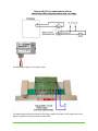
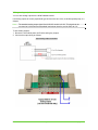
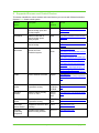
© 2008 Climate Automation Systems.
All Rights Reserved. No part of this document may be photocopied, reproduced, stored in a retrieval system, or
transmitted, in any form or by any means whether, electronic, mechanical, or otherwise without the prior written
permission of Climate Automation Systems.
No warranty of accuracy is given concerning the contents of the information contained in this publication. To the
extent permitted by law no liability (including liability to any person by reason of negligence) will be accepted by
Climate Automation Systems, its subsidiaries or employees for any direct or indirect loss or damage caused by
omissions from or inaccuracies in this document.
Climate Automation Systems reserves the right to change details in this publication without notice.
Windows is a trademark and Microsoft, MS-DOS, and Windows NT are registered trademarks of Microsoft
Corporation. Other product and company names herein may be the trademarks of their respective owners.
Climate Automation Systems
404.831.2762
gogreenwithENV.com
Table of Contents
1
About this Guide ............................................................................................................................ 4
Audience .........................................................................................................................................4
Scope ..............................................................................................................................................4
Typographical conventions .............................................................................................................4
2
Overview of the System ................................................................................................................. 5
System architecture ........................................................................................................................5
Prerequisites to installation .............................................................................................................6
3
Installing the Input/Output Module ................................................................................................. 7
Installation location .........................................................................................................................7
Mounting the I/O module.................................................................................................................7
Connecting power to the I/O module ..............................................................................................7
4
Installing the VLinx Serial Server ................................................................................................... 9
Mounting the VLinx serial server ....................................................................................................9
Connecting power to the VLinx serial server ..................................................................................9
Connecting the VLinx serial server to the network .........................................................................9
Configuring the VLinx serial server .................................................................................................9
5
Installing Thermostats .................................................................................................................. 11
Installing a communicating thermostat .........................................................................................11
6
Communication Wiring ................................................................................................................. 12
Communication wiring options ....................................................... Error! Bookmark not defined.
Communication wiring for Ethernet to VLinx serial server to I/O module ..... Error! Bookmark not
defined.
Communication wiring using a USB to RS485 converter .............. Error! Bookmark not defined.
7
Wiring Equipment to the I/O Module ............................................................................................ 13
Wiring analog and digital inputs ....................................................................................................13
Wiring digital outputs.....................................................................................................................14
Wiring analog outputs ...................................................................................................................18
8
Supported Sensors and Control Devices..................................................................................... 19
Installation Guide
Page 3 of 20
Copyright 2009
1
About this Guide
This guide provides the instructions for installing and configuring Climate Automation Systems’ ENV
climate control system.
Audience
This guide is intended for control contractors and mechanical contractors who install the components
of the ENV climate control system including sensors and field wires.
This guide assumes that you have some knowledge of basic low-voltage electrical wiring.
Scope
This guide provides all the information you need to install, configure, and start running the ENV
climate control system.
Typographical conventions
This document uses the following typographical conventions:
• Command and option names appear in bold type in definitions and examples. The names of directories, files, machines, partitions, and volumes also appear in bold.
• Variable information appears in italic type. This includes user-supplied information on command
lines.
• Screen output and code samples appear in monospace type.
In addition, the following symbols appear in command syntax definitions.
• Square brackets [ ] surround optional items.
• Angle brackets < > surround user-supplied values.
Installation Guide
Page 4 of 20
Copyright 2008
2
Overview of the System
ENV is an energy management system that controls, manages, and monitors all aspect of a
building’s environment. ENV is the first system of its kind to take intelligent climate control
technologies and bring them to the residential and commercial market. ENV uses real-time weather
information and the rules of a sustainable ENVironment to control any device in the building or
mechanical room (regardless of the manufacturer) to balance all aspects of the building’s
ENVironment and create the ideal climate for comfort, human well being, and energy reduction.
System architecture
The ENV software runs on a computer running Microsoft® Windows™ Vista Business.
The following diagram illustrates a typical installation of an ENV.
1. All devices being monitored or controlled are wired directly into an IO block, which is an A/D
convertor. The wiring to the IO block is low voltage. So, to switch a high voltage device on
and off, a relay must be used. Each IO block has a set of IO points to which the wires
connect. Each point has a unique address within each IO block.
2. The IO blocks are interconnected and daisy chained to the VLINX device which converts a
RS485 serial signal to Ethernet. In this way, the IO blocks are IP addressable and can be
seen from anywhere on the intranet.
3. If a forced air system is to be controlled by ENV, communicating thermostats are used. The
thermostats use four wires from the wall mount into the mechanical room to a control device
that comes with each thermostat. The control device is wired directly to the appropriate air
handler or heat pump. In this manner, the thermostats function as ordinary thermostats.
Each of the thermostats’ control device has a pair of wires that communicate RS 485 and
daisy chain and connect to the VLINX just like the IO block. They can daisey chain through
the IO block but that is not a requirement.
4. The VLINK is connected to a router or to switch within the building. In this way the VLINX is
visible on the intranet.
5. The PC is also connected to the intranet within the building and is able to communicate with
all of the IO blocks and with the thermostats via Ethernet.
Installation Guide
Page 5 of 20
Copyright 2009
Prerequisites to installation
Before you begin installation of the ENV climate control system, ensure the following are available:
• an active external network connection
• a router
Installation Guide
Page 6 of 20
Copyright 2008
3
Installing the Input/Output Module
The ENV climate control system uses one or more input/output modules to interface with the climate
control devices. Currently, the following Modbus-compatible DataNab input/output modules are
certified for use with the ENV system:
Module
Analog
Inputs
Ai8_R13
81
AiO8
81
Ai32
321
Analog
Outputs
84
Digital
Inputs
Digital
Outputs
Pulse
Counter
Comment
8
132
Yes3
A total of 8 universal inputs (analog,
digital, or counter - max. rate is 100
Hz) and 13 Digital Outputs.
8
No
8 universal inputs (analog or digital)
and 8 analog outputs which can drive
0-10 volt analog devices or external
relays.
32
No
32 universal inputs (analog or digital)
1. Digital input may be a dry contact or an NPN open collector transistor (jumper set to thermistor) or
external voltage (0v=off, 5v =on).
Analog inputs may be directly connected thermistors, 0-5 volts or 0-20 milliamps (internal jumper
selectable per input).
2. Outputs are isolated normally open single pole contacts.
3. Any input can also be a high speed counter in an Ai8_R13 only. Input must be a dry contact or an
NPN open collector transistor - 100Hz maximum.
4. The AiO8 can drive relays for use as a digital output as well as provide a 0-10 volt output.
Installation location
Mount the module in a low-voltage enclosed panel.
Environmental operating range:
• 50º to 99º F (10º to 50º C)
• Relative humidity should be 10% to 90%, non-condensing
Mounting the I/O module
Mount the modules in one of the following ways:
• using a DIN rail (preferred for quick change-outs)
• using four screws and the mounting holes provided on the cover plate
Be sure to leave space either side of the module for wiring.
Connecting power to the I/O module
Each DataNab I/O module consumes about 100 milliamps; take care not to exceed the power supply
rating based on the number of devices plus any auxiliary relays or externally powered sensors that
use the same power.
Power requirement is typically 12 to 24 volts DC or AC.
Note:
An Ai08 must be powered with 24 volts DC or AC to achieve full voltage (10 volts DC) on the
analog outputs.
Installation Guide
Page 7 of 20
Copyright 2009
To connect power:
1. Make sure that the power source is off.
2. Connect the power wires to the module’s lower power terminals labeled 24VAC and
. If using a
DC power supply, connect the positive (+) wire to the 24VAC terminal and the negative (-) wire to
the
terminal.
Caution: When wiring an Ai8_R13, make sure you connect power to the correct terminals.
DO NOT connect to the upper terminals labelled POWER.
Note:
When using more than one module, you can daisy-chain the power wiring between
modules.
3. Plug in the wall-plug power supply.
4. If the Power LED on the I/O module does not come on, make sure that power is present at the
module’s power input terminals and that polarity (if DC) is correct.
Installation Guide
Page 8 of 20
Copyright 2008
4
Installing the VLinx Serial Server
The preferred PC to I/O module communication option requires a VLinx serial server. This section will
guide you through installing the Ethernet to RS485 serial server.
Mounting the VLinx serial server
Mount the VLinx serial server into the same enclosed panel as the I/O module in one of the following
ways:
• using a DIN rail (preferred for quick change-outs)
• using four screws and the mounting holes provided on the cover plate
Be sure to leave space on either side for wiring.
Connecting power to the VLinx serial server
To connect power to the VLinx serial server:
1.
2.
3.
4.
Set the DIP switches on the VLinx serial server to the OFF position.
Connect the power cable to the DC-IN jack on the top of the VLinx serial server.
Plug in the wall-plug power supply.
If the Power LED is not lit, make sure that 12VDC is present at the power input terminal.
Connecting the VLinx serial server to the network
To connect power to the VLinx serial server:
1. Connect one end of a standard Ethernet network cable to the VLinx serial server.
2. Connect the other end of the network cable to the router.
Configuring the VLinx serial server
To configure the VLinx serial server (match the settings illustrated in the figure below, i.e., Server
Properties):
1. Download the VLinx documentation from http://www.bb-elec.com/product_family.asp?familyid=2.
2. Using the VLinx documentation and the VLINX software, set the VLinx serial server address to a
unique network address. Typically this should be 192.168.1.91 but could vary based on the IP
ranges used by the installed router.
3. Set the VLinx serial server port number to 4000.
Note:
You can use any port number as long as you specify the correct port number when you
configure the ENV climate control system software.
4. Set the serial communication parameters to 9600 baud, 8 data bits, and no parity.
5. Open the VLINX by removing the two screws on the side. You will see two jumpers on pin 78.
Move them to the location shown below so that they are placed across the two pins in each of the
two locations.
Installation Guide
Page 9 of 20
Copyright 2009
Installation Guide
Page 10 of 20
Copyright 2008
5
Installing Thermostats
Include a communicating thermostat as part of the system when managing a typical forced air heating
and cooling system. You can also use a communicating thermostat to control a radiant heat zone
where traditional readout and manual setpoint adjustment is still desired at that location.
Installing a communicating thermostat
Communicating thermostats provide a way for the controlling computer to manage traditional forced
air thermostats through a browser interface. The number of zones will determine the quantity and
type of communicating thermostats.
Climate Automation Systems has approved the Residential Control Systems, Inc.
(http://www.resconsys.com) TR16 communicating thermostat for use with the ENV system. Refer to
the RCS manuals found at http://www.resconsys.com/products/stats/serial.htm for installation
instructions and for instructions on how to set a unique address for each thermostat.
Tie the communicating thermostats to the ENV system by connecting (daisy chaining) a pair of wires
to the RS485 terminals of each thermostat and continue to other RS485 devices. Ultimately the pair
of wires should terminate at the VLinx. A grounding wire should also be included and daisy chained
throughout.
Installation Guide
Page 11 of 20
Copyright 2009
6
Communication Wiring
After you install the various components of the ENV climate control system, you must set up the
communication wiring so the components can communicate with the PC.
To connect communication wiring:
1. Connect the VLinx converter to the network through a router or hub using a standard network
cable.
2. Connect the VLinx serial server to the RS485 terminals on the I/O module using a 24 AWG to
18AWG twisted pair copper wire (you can also use raw Cat-5 cable) or you can purchase a 9Pin
female cable from Radio Shack and cut off one end to expose the wires and trace them back to
pins 3-5 as follows: Pin 3 is plus and pin 4 is minus and pin 5 is ground.
3. Connect the computer to the network through a router or hub using a standard network cable.
Installation Guide
Page 12 of 20
Copyright 2008
7
Wiring Equipment to the I/O Module
Use a maximum wire size of 18AWG for wiring inputs and outputs. A 22AWG wire is the
recommended size for inputs.
If you must run analog signal wiring a long distance or through areas with electrical interference, use
shielded wire. The shield should be connected to ground only at the panel end.
Wiring analog and digital inputs
You can wire analog and digital inputs to the following DataNab modules:
• Ai8_R13
• AiO8
• Ai32
Use analog inputs to monitor temperature, amps, or voltage. Typical analog sensors include
thermistor based temperature sensors. The ENV system is capable of handling either a 10K Type II
or a 10K Type III industry standard thermistor.
Use digital inputs to monitor status or alarms, such as damper position or a water sensor. Traditional
digital inputs are either a dry contact or open collector transistor from a device.
To wire inputs:
1. Be sure the I/O module power is off before wiring any inputs.
2. Connect analog input wiring as follows:
Installation Guide
Page 13 of 20
Copyright 2009
3. Connect digital input wiring as follows:
4. If the input is DC volts or milliamps, remove the module cover and set the configuration jumper for
the input to indicate the type of input used. Make sure the jumper is positioned correctly for each
input, as follows:
Note:
The default jumper setting is THERM (thermistor or dry contact).
Wiring digital outputs
You can wire digital outputs to the following DataNab modules:
• Ai8_R13 (direct and using an external relay)
• AiO8 (using a 12 volt DC external relay)
The Ai8_R13 has a single pole normally open contact built-in per output (total of 13). These can be
used to switch low voltage loads directly or high voltage loads via an external relay.
To wire digital outputs:
1. Be sure the I/O module power is off before wiring any outputs.
2. To use the Ai8_R13 to drive low voltage loads without an external relay, connect the wiring as
follows:
Installation Guide
Page 14 of 20
Copyright 2008
3. To use the Ai8_R13 to drive high voltage loads (120VAC or greater), use an external load relay to
separate the high voltage from the I/O module. Connect the wiring for driving a pump or heater as
follows:
4. An alternate method requires no 12-24 volts external volts for the coil. By using an RIB21CDC or
similar relay (available from Kele at www.Kele.com), the 2 low voltage control wires can be
connected directly to the contact output of the A8_R13. See the following diagram for using this
method:
Installation Guide
Page 15 of 20
Copyright 2009
The AiO8 only provides a 0-10 volt DC output:
The AiO8 always requires an external 12VDC relay to switch any load as it only outputs a 0-10 volt
signal. The power for the relay comes from the AiO8.
Installation Guide
Page 16 of 20
Copyright 2008
When using an external 12 volt DC relay, the energize voltage must be10 volts or less. The coil
impedance must be greater than 500 ohms.
An RIBTU1C (single pole double throw) or RIBTU2C (double pole double throw) relay is an ideal
external relay for use with the AiO8 I/O module as it can handle loads of 10 amps resistive or 1/3 HP
motor at 240 volts AC. Kele is a good source for this item at www.Kele.com.
Refer to the following figure:
Note:
You can manually override each output using the Hand-Off-Auto switches as follows:
Hand – Forces output to the ON state
Off – Forces output to the OFF state
Auto – Allows the output to follow the last command from the computer
Installation Guide
Page 17 of 20
Copyright 2009
Wiring analog outputs
You can wire analog outputs to the AiO8 DataNab module.
Use analog outputs to control proportional type devices such as a valve, a variable speed pump, or a
damper.
Note:
The standard analog output signal of an AiO8 I/O module is 0-10V. This signal can be
converted to 0-20mA with an associated load resistor sized to provide 20mA at 10V.
To wire analog outputs:
1. Be sure the I/O module power is off before wiring any outputs.
2. Connect the output wiring as follows:
Installation Guide
Page 18 of 20
Copyright 2008
8
Supported Sensors and Control Devices
This section identifies the various sensors and control devices you can use with Climate Automation
Systems’ ENV climate control system.
Sensor/
Device
Description
Part
Number
Source
I/O Module
Modbus module with 8
channel analog inputs and
13 relay outputs
Ai8_R13
http://www.datanab.com/controllers/
Ai8_R13.htm
I/O Module
Modbus module with 8
channel analog inputs/
analog outputs
AiO8
http://www.datanab.com/controllers/
AiO8.htm
I/O Module
Modbus module with 32
channel analog
Ai32
http://www.datanab.com/controllers/
Ai32.htm
Communicating
thermostat
Connects to, monitors, and
controls an HVAC
mechanical system
TR16-485
http://resconsys.com
TR40
http://www.automatedoutlet.com/pro
duct.php?productid=221
or
http://www.asihome.com/ASIshop/p
roduct_info.php?products_id=1291
or
http://www.discounthomeautomatio
n.com/cgibin/main/co_disp/displ/category_id/
724/product_id/6925/RCSCommunicating-Thermostat-RS485
VLINX
Serial to Ethernet converter
esp901
http://www.bbelec.com/product_family.asp?family
id=2
Temperature
sensor
Provide precision remote
temperature sensing
ST-R3 or
ST-R3S or
ST-R3R
http://www.kele.com/olcat/t1/10288.
html
Humidity
sensors
Measure relative humidity
from 0% to 100%
KHD or
KHO or
KHR
http://www.kele.com/olcat/h2/10820
.html
Immersion
sensor
Provides precision remote
temperature sensing
ST-W3E
-XHP
http://www.kele.com/olcat/t1/10297.
html
Duct temperature sensor
Temperature sensor for duct
mounting
KTD3
http://www.kele.com
Thermal
conducting
compound
Facilitates heat transfer
between mating surfaces
TCC-111
http://www.kele.com
Installation Guide
Page 19 of 20
Copyright 2009
Thermocouple
probe
High pressure sensors for
mounted NPT security
TC-NPT
http://www.omega.com/ppt/pptsc.as
p?ref=TC-NPT
Thermocouple
with protection
head
Industrial thermocouples
with protection heads
Various
http://www.omega.com/ppt/pptsc.as
p?ref=NB1-ICIN_INDUST_TC
Temperature
transmitters
Converts thermocouple or
RTD signals into a 4 to 20
mA dc signal output
TX90A
Series
http://www.omega.com/ppt/pptsc.as
p?ref=TX91A_92A&Nav=temn01
Variable speed
controller
Controls most single phase
AC pumps and motors
PSC-1
http://www.innovextechnologies.co
m/pdf/iWorX%20PSC1%20User%20Guide.pdf
Humidity
transmitters
Provides precision humidity
measurement
GEH
Series
http://www.kele.com/olcat/h2/11033
.html
KWH meter
Provides active electricity
measuring
EKM25IDS
http://kwhmeters.com/EKM_Meterin
g/Basic_Pass-through_Meters.html
KWH meter
KWH monitoring for a
120vac load
EKM-15E
http://kwhmeters.com/EKM_Meterin
g/120V,_External_CT_Meter.html
Multi-voltage
relay modules
Remote relays for control or
status feedback
PAM-1 or
PAM-4
http://www.kele.com/olcat/rc15/102
17.html
Installation Guide
Page 20 of 20
Copyright 2008