1
SERVICE MANUAL
HOBS
© Electrolux Distriparts
Muggenhofer Straße 135
D-90429 Nürnberg
Germany
Fax +49 (0)911 323 1022
DGS-TDS-N
Ausgabe: 04.08
DGS-TDS-N
21.04.08
Publ.-Nr.
599 519 523
685
EN
Repair-Instruction
for induction hobs
2
599 519 523 EN
1 General Information
These instructions serve the repairing of autarkic cooking hobs and cooking hobs in combination with
an oven with 3 or 4 inductions cooking zones respectively of the type E.G.O.. Also includes hobs with
2 induction zones (Domino, Mixed, Mixed gas) and the Frontline appliance series.
Please search for the corresponding alarm
symptom and then go through the alarm remedy measures from top to bottom.
Information concerning the replacement of parts is to be found in the corresponding replacement
instructions or are included with the spare parts.
All work is only to be carried out on the induction modules and the heating elements are only to be
carried out after they have been disconnected.
1.1
Leak current
A leak current of 5mA is normal and is therefore much higher than with other appliances.
1.2
Standby
The Standby power consumption amounts to < 1W (Induction plus user interface in the autonomous,
exception Frontline up to 2W).
The µprocessor for the measuring of the coil temperature is deactivated in standby, i.e. should the
cooking hob be heated up to hot pan being on the zone, no heating display "H“ is displayed when
switched off.
In this condition, the ventilator is also not switched on by external heating.
DGS-TDS
21.04.08
3
1.3
599 519 523 EN
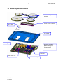
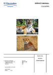
Block Diagram/Hob elements
Coils incl. Temperature
sensors.
Touch control w. carrier
Cover plate
Coil carrier
Cooling fan
Induction module w.
plastic housing incl.
mains terminal
Filter pcb
Power mod. Left
PowerMod. Right
DGS-TDS
21.04.08
4
599 519 523 EN
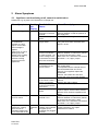
2 Alarm Symptoms
2.1
Appliance not functioning at all, cannot be switched on
References e.g. (1) refer to the illustrations in Chapter 2.8
Alarm Symptom
Cooking Possible Alarm
Hob
Cause
Display
Alarm Remedying
House fuse triggered
None
(1) Test the pin assignment and
230VAC between N and the phases on
the supply line.
See chapter 3 Testing Power Component
Cooking field cannot
be switched on.
Normally no "pips"
approx. 4 sec. after
mains voltage is
applied
respectively no quick
flashing up of the
display in the cooking
zone with not selfsufficient cooking
zones or front line
appliances.
None
Incorrect connection at
the power connection
terminal.
Final induction phase
defect.
Electronic system no
longer reacts
No mains voltage or
incorrect connection
(1 phase missing ->no
control voltage; N not
connected to terminal 4
and 5 not connected)
(1) Test the pin assignment and
230VAC between 4 N and the 2 phases
on supply line terminals 1 and 2.
Both of the "N“s should be connected to
terminals 4 + 5, if appr. jumper.
Disconnect the appliance from the mains
using the house fuse, reactivate after
approx. 10 sec..
No 5VDC betw. Pin 1 +
3 of the Bus for the
Touch Control
(2) Test 1+3 5VDC on the underside of
the cooking field
(corresponds with the external lines of
the bus between filter and Touch
Control), if not applied, replace the
Filterboard.
Caution: this is difficult to test from
underneath using normal test probes!
Connector of the cable (3) Test connector at the filter and Touch
to the Touch Control /
Control.
Display not inserted.
Reapply the mains voltage.
Fuse strip conductor burnt See chapter 3 "Check power section'"
out and/or final induction
phase defect
Touch control/display
defect.
Every 5-10 sec "beep"
of touch control
None
Only Frontline
All
appliances: cooking
indications
zone can not be
ON
activated. Display fully
on for more than 5 sec.
DGS-TDS
21.04.08
N not connected to
terminal 4 or 5.
Flat band cable
between user interface
and glass (touch
keyboard) not plugged
correctly.
If 5VDC exist and power component already
replaced: replace Touch Control, ensure
that the Touch Control is applied to the
glass.
(1) Test the pin assignment and
230VAC between 4 N and the 2 phases
on supply line terminals 1 and 2.
Both of the "N“s should be connected to
terminals 4 + 5, if appr. jumper.
Check line for seat and correct position
(contact direction), see capter
"References Frontline"
5
2.2
599 519 523 EN
Individual cooking zones do not work (partially) or work incorrectly or
cannot be used
Alarm Symptom Cooking Possible Alarm
Hob
Cause
Display
Alarm Remedying
Pan does not heat
up.
Pan in the border
area of the pan
detection and only
works with low power
Pan not detected.
Use different pot or this pot on a smaller
hob. See Chapter 4 Pot Detection
Information
Touch Control defect.
1) See Chapter 5. Touch Control Autarkic
Cooking Hobs Information..
2) Should this not help, replace Touch
Control.
(4) Change installation situation.
Normal
cooking
phase
Flashing
"F“
Display "F" with 2
hobs with all pots
(also 1 hob with 3
hob models)
Flashing
"F“
No power on all hobs Normal
cooking
phase
Individual buttons
cannot be used or
cannot always be
used.
Cooking hob power
Normal
too low or not
cooking
provided for a longer phase
duration.
Check whether the pots or pans are
suitable for induction. See 4 Pot Detection
Information
Coil not correctly
Check whether the coil lines are connected
connected.
and the torque has been adhered to.
Distance between coil Check whether the coil is applied to the
and glass ceramic too glass ceramic and whether the glass was
large.
pushed was pushed down when screwing
in position.
1 phase missing ; only (1) Test the pin assignment and
possible with
230VAC between 4 N and the 2 phases on
induction SW.Ver.
supply line terminals 1 and 2.
0.50.
Both of the "N“s should be connected to
terminals 4 + 5, if appr. jumper.
Should the above not succeed, replace the
affected power component..
Demo mode
See Chapter 5.2
activated.
Incorrectly installed,
exhaust not possible
to the front.
Unsuitable pots
(bottom bent)
Induction coil is not
applied to the glass
ceramic
Fan does not start.
"H" in display when
cooking hob and
oven cold and
switched off.
DGS-TDS
21.04.08
"H“
Temperature sensor
defect.
See Chapter 4 Pot Detection Information
Check whether the glass ceramic was
pushed down when being screwed in
position and the coil has been correctly
positioned.
1) When setting a cooking phase >0, the
fan runs at a slow speed. If not, check the
fan for foreign bodies, remove these where
appropriate.
2) If necessary, replace fan.
3) Should this not succeed, replace power
component.
Replace corresponding coil with
temperature sensor. Also see Instructions
"E4“.
6
2.3
599 519 523 EN
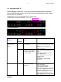
Alarm message "E“
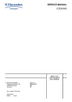
When the appliance is switched on, "E“ / „xx“ Alarm Number is displayed in the timer display. With
Frontline the display of the front zone indicates the error number when switching on. The affected
zones are subsequently displayed with an "E" in the cooking phase display and are thereby disabled.
The other zones can still be used.
example (left touch control / right indication in the cooking zone):
1) Display alarm number after switching on for 10 sec.
Alarm number
E5
2) 2 zones are disabled.
0
E
Alarm
Symptom
E
0
Display in Possible Alarm
the
Cause
Cooking
Hob Timer
Alarm display in the "E0“
Touch Control
display.
Incorrect configuration on
the Filterboard.
"E3“
Under voltage or over
voltage, is only displayed
for 10 sec. after voltage
has been applied.
"E4“
Coil temperature sensor
defect or not correctly
connected.
DGS-TDS
21.04.08
Alarm Remedying
Disconnect cooking hob from mains,
wait 10 sec and reconnect the mains
supply.
Should alarm still be displayed,
replace filterboard..
1) Disconnect cooking hobs from the
mains, wait 10 sec. and reconnect the
mains.
2) Should alarm still be displayed,
test L1 against N (4),
test L2 against N (5) at the mains
connection (1).
3) If OK, see
See Chapter 3 Testing Power
Component
1) (5)Inspecting the contacts on the
power component.
Is the connector inserted?
2) The resistance at room
temperature (25°C) amounts to 1000
Ohm. This corresponds to approx. 3.3
Ohm per +1°C deviation.
If not in this range, replace affected
coil including temperature sensor.
3) Should above not succeed, replace
power component concerned.
7
Alarm
Symptom
Display
in the
Cooking
Field
Timer
Alarm display in the "E5“
Touch Control
"E6“
Possible Alarm
Causes
Alarm Remedying
1 phase missing
1) Check the house fuse.
2) Check the pin assignment, (1)
test L1 against N (4),
test L2 against N (5)
3) If ok, see Chapter 3.
1) (5)Checking of the contact with the power
element.
Is the temp. Sensor connector locked in place
or the dummy connector (3 zone appliances,
no coil connected) inserted?
2) The resistance at room temperature (25°C)
is 1000 Ohm.A deviation of +1°C
corresponds to approx. +3.3 Ohm
Replace the corresponding coil incl.
Temperature sensor if not in this zone.
Communication
interference
between filter and
power component.
or temp. Sensor is
defective/missing
"E7“
"E8“
"E9“
DGS-TDS
21.04.08
599 519 523 EN
Note: a norm
requirement with
regard to new
powerboards results
in the power supply
for the electronics
on the powerboard
being deactivated in
the case of a
missing or incorrect
temp. sensor value.
Alarm Temperature
sensor heat sink
power component
Communication
interference betw.
filter and Touch
Control.
Central line at
RAST2.5 connector
/ line defect.
Incorrect
configuration for the
Touch Control on
the Filter board.
1) Check the cables between the two boards.
(6), Reinsert connector.
Or replace cable.
2) Should all of the zones on the cooking hob
be affected (Display "E" in the cooking phase
display), replace filter board .
3) Should the above not succeed, replace
power component.
Replace affected power component.
1) (3) Inspect connector at filter and the
Touch Control. Replace cable or filter and
Touch Control.
Reconnect mains voltage.
2) Should above not succeed, replace Touch
Control.
3) Should above not succeed, replace Filter
board.
Disconnect cooking field from the mains. Wait
10 sec. and reconnect to the mains voltage.
Should alarm still be displayed, replace Filter
board.
8
2.4
Other alarm symptoms
Alarm
symptoms
Display
Buzzer defect
Individual display
elements do not
illuminate or do not
do so continuously.
Penetrating aromas
from the hob when
warm.
Pots cause noises
2.5
599 519 523 EN
Possible Alarm
Cause
Alarm Remedying
Touch control
defect.
Defective display
elements
Replace Touch Control.
Coils subjected to a
manufacturing
defect.
Unsuitable pots.
Normal sound level
The aroma is non-toxic. Replace the affected
coils. These also have a slight arom when
cold. Clean the glass and aluminium sheet.
See Chapter 4 Pot Detection Information.
Interference noises result from the high
working frequency of the induction. This can
vary from pan to pan.
When measured in operation pursuant to
EN60335 §11-3 pursuant to EN60704 with 4
pots <47dBA.
A pot with boiling water has approx. 6062dBA.
Replace Touch Control.
Cooking zone with electric heating element not functioningt
Alarm symptoms
Possible Alarm Cause Alarm Remedying
Cooking zone not
functioning.
No phase 2 power voltage
or wrong connection
Electric heating element
defect
Relay defective
If the above should not
succeed.
DGS-TDS
21.04.08
(1) Check the pin configuration and
230V AC between N (4) and the phases
at terminals 1 and 2.
(7) Check whether the electric heating
element is open between the connections
or whther it has short-circuited. Replace
the heating element if defective.
8) Check whether the rely is defective
and whether no voltage is applied to the
electric heating element. Also refer to the
circuit diagram.
Replace the filter module with the relay
9
599 519 523 EN
(1)
(7)
(8)
2.5.1 Electric heating element relay instructions
•
•
2.6
Refer to the wiring diagram xxx.
The electric heating element is pulsed on relay board HOC2000 in the cooker.
Phase commutation with the cooker/hob combination, refer to Chapter 2.6, special error
images for the cooker/hob combination.
Special error images for the cooker/hob combination
•
•
•
•
Peculiarities:
Output
L2 is not continuous and is only connected through when the right zone is switched through
(D37 / D39, Details, refer to the wiring diagram).
The display in the hob is supplied with 5V DC from the induction module.
The electronic hob control in the cooker is supplied with 5V DC from the HOC2000
powerboard in the cooker.
Mixed with the electric heating element:
with the cooker/hob combination, the phases are normally connected to the
L1
left cooking zone
L2
right cooking zone
The induction module (front left and right cooking zones) are however connected to the
continuous phase L1.
Therear right electric heating element zone is always connected to L2.
L2 is only available however of one of the right cooking zones is switched on.
In order to avoid an overloading of L1, the rear left zone is therefore operated with L1 (D29) or
L2 (D37) if the front right zone is switched on.
The phase commutation is executed with the assistance of relays K501 and K504
A safety conductor strip (9) conductor strip of the K501 which can trigger a relay in case of an
error occurring (e.g. contact stuck together).
The output of the 210mm induction cooking zone is set to "P" if none of the right zones are
switched on and the rear left zone is fully switched on, without this display being released.
DGS-TDS
21.04.08
10
599 519 523 EN
(9)
2.6.1 No display or error display on the cooking zone display on the cooker
Alarm symptoms
Display
Error display "E".
"E" if the
display
exists.
When voltage is applied, the
hob display illuminates
briefly.
But: no display at the cooker,
no display at the hob, no
output at the induction zones.
DGS-TDS
21.04.08
Possible Alarm Cause Alarm Remedying
Errors in the cooking zone display in
the cooker concern the hob. I.e. the
same error number is displayed as in
the hob display. For error displays,
refer to Chapter 2.3. Error display "E".
hob control in the cooker
defective.
Additional instructions and tips
concerning cooker problems are to be
found in the Competence Service
Manual Doc. No. xxx.
11
599 519 523 EN
2.6.2 Cooking zone at the cooker okay, no display at the hob or no output.
Alarm symptoms
Display
The diplay in the hob does
None.
not illuminate when voltage is
connected.
Cooker display okay.
But: no cooking stage display
at the hob, no output at the
induction zones.
Possible Alarm Cause Alarm Remedying
Output connector not
inserted..
Check the connector (10) and
the cable, check that it is
correctly engaged.
No cooker output.
Check pin D35 at the output
connector to determine
whether 230V AC voltage is
connected.
Communication connector
1) Checking the connection
not inserted or line
between cooker / hob (11).
damaged.
2) Hereby also explicitly check
the entrance point of the cable
at the hob for damage (14).
3) Check the seat of the
connector at the display in the
hob (12) to the induction
module or (13) to the cooker /
external user interface, ditto
induction module.
No 5V DC betweem Pin 1+3 (2) check 5V DC Pin 1+3 on
of the display bus
the underside of the hob.
(corresponds to the our lines
of the bus line from the filter
to the display), if not
connected, replace the
filterboard. Caution: it is
difficult to measure this from
below with normal test probe!
Display defect
When voltage is applied, the
hob display illuminates
briefly. Display at cooker is
okay.
But: no output at the
induction zones
DGS-TDS
21.04.08
Replace display
See normal diagnosis chapter
2.2, individual induction
cooking zones do not
(temporarily) work or
incorrectly or cannot be
operated or see 2.3 chapter
error display "E"
12
599 519 523 EN
(10)
(11)
(12)
(13)
(14)
Display in the hob
4 hobs dep. In comb. With cooker
(14)
external user Interface
2.7
Unknown display
For details, refer to the cooking field instruction manual
Symbol
„.“
„-“
„A“
„E“
„F“
„H“
„L“
„P“
„∪“
DGS-TDS
21.04.08
Comment
Intermediate cooking levels („4.“)
Induction – zone switched off because of over temperature at the coil sensor (empty
pot)
Fast heating up function („Ankochstoss“)
Alarm display siehe 2.3 Alarm message "E“
Pot detection – no pot detected
Residual heat indication
Lock – Function or key lock
Power (booster) function for induction
Keeping warm
13
2.8
599 519 523 EN
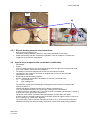
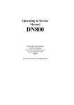
Control Point Illustrations
(2)
Terminal
1
2
3
4
5
Pin 1, 3
(1)
(5)
(3)
(4)
Air inlet
Min. 5 mm
Min. 20mm
Oven
Remark: if there is no ventilation gap in the front it’s still possible to operate the hob. Only with longer useage ( >15 min. ) the
performance will drop. For Mixed hob this is e.g. – 20%, for full induction hobs it’s higher.
DGS-TDS
21.04.08
14
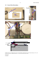
2.9
599 519 523 EN
Images control point for 2 zones / Mixed Induction
(1)
(5)
(7)
(6)
(3)
Attention: mains connection for Domino is directly on filter pcb.
(1) Domino
(3)
(2)
DGS-TDS
21.04.08
15
599 519 523 EN
3 Testing Power Component
1. When alarm messages and disabled zones exist ("E“ in cooking phase display), please make
a note of the power component which is affected.
2. (7) Check whether the lead from the filter board is connected, also check the bus lines (6)
µprocessors filter to power component.
3. If (8) IGBT has become shorted, this normally means that the IGBT housing is damaged.
Replace power component
4. (8) Measure resistance at the IGBTs
Pin1-Pin2 or Pin2-Pin3
>50kOhm
Æ Okay
<50Ohm
Æ power component defect & replace
Only replace the affected power component and (9) insert 20A fuse, completely separate the
fuse strip conductor.
S12 = right power component
S11 = left power component
5. By a short-circuit and destroyed power component, it is imperative that the coil lines be
inspected for signs of damage.
6. Also replace the filterboard should the replacement of the power component not succeed.
(6)
(9)
(7)
(7)
(6)
(8) 8 St. IGBT
Pin 1 2 3
DGS-TDS
21.04.08
16
599 519 523 EN
4 Pot Detection Information
Suitable pot materials:
• Steel enamel
• Stainless steel (with magnet. bottom)
• Aluminium (with magnet. bottom)
• Cast iron
Unsuitable materials:
• Aluminium (Æ too much power)
• Copper
• Stainless steel (not magnetic)
• Glass
• Ceramic
The pot detection is designed for the following diameters:
Nominal burner ∅ [mm]
Minimum pot bottom ∅
instruction manual [mm]
145
180
210
260
125
145
180
180
Minimum pot bottom ∅
adjusted with steel plate
[mm]
100
120
140
180
With regard to Ind. G4, the same diameter is stipulated in the instruction manuals as for the previous
model. However, the real diameter which still functions is much smaller.
The performance for different pots can very by as much as +/- 10-15%.
•
•
•
As reference pots, we recommend enamelled steel pots (e.g. Silit).
2-3 mm thick round steel plates in various diameters are very suitable for testing the pot detection
function.
Sandwich bottoms can cause very unpleasant noises if they are not correctly pressed. The same
is the case with regard to handles which are a little loose.
•
The bottom diameter of the pot is decisive and not the
exterior diameter.
•
With regard to stainless steel pots with sandwich bottoms,
the diameter of the magnetic part of the pot bottom is
decisive.
•
an additional influencing factor is the vertical distance from
the coil, i.e. an uneven sandwich bottom has a negative
effect on the power consumption. The effect is exactly the
same if the induction coil is not pressed on the glass
ceramic.
DGS-TDS
21.04.08
17
599 519 523 EN
5 Touch Control Autarkic Cooking Hobs Information
•
5.1
The Touch Control works on the basis of the infrared principle, i.e. a signal is transmitted with a
transmitter which is then reflected by the finger and received once more.
Instructions on the operation / possible operation errors if the buttons do
not function:
•
Do not use with the flat finger. Hold the finger relatively upright.
Otherwise 2 buttons can be activated, this is not signalled.
•
Please do not approach slowly, especially not from the side, it is better to approach the button
faster.
A signal change is above all evaluated.
•
Applying excessive pressure to the cooking hob will not make a difference.
It is better to release it for 5 sec. and then press the button again.
•
If the adjustment of the cooking stage/timer does not continue after the button has been released,
this is due to the fact that the Touch Control receives a "Button Pressed" signal even from a
distance of some mm.
If the user interface is not adjacent to the glass ceramic, the signal for the key evaluation is very
much smaller and the keys can not be operated any more, i.e. pay always attention to intact
plastic carriers.
•
If the appliance switches off without that the glass ceramic has been touched, is this because a
key in the extreme case.is switching even in a distance / height of 10 mm. This is the function
principle of the touch control and is a normal behaviour. I.e. do not replace the touch control!
DGS-TDS
21.04.08
18
5.2
599 519 523 EN
Demo mode / Self test (Service mode) / Alarm Menu
To enter the self-test/Demo mode, the following sequence of buttons must be pressed:
1. Hob is off. Press main switch continuously until display is going off (without beep).
2. Press the "+" and " -" buttons of the front zones together (->short beep) for about 3 seconds (->
again short beep)
3. Press the timer selection key
Step 1
Step 3
d.
Step 2
4. The display shows a "d" for demo mode.
If you press the timer select key again you switch to “S” for Service mode,
another press gets you to “E” the alarm menu.
5. By pressing the button "+" of a cooking zone you activate the menu.
For example, status like above shown in the graphic – hob is in demo mode,
press ‘+’ key of zone to deactivate the demo mode.
Demo Mode:
If demo mode is activated the display with the „d“ shows additionally a dot.
After selecting the demo mode, the electronic goes to off. Now it can be used like usual but only
without heater activation. The deactivation of the demo mode is done in the same procedure as
activating. After deactivating the demo mode the electronic must go off. Now the hob can be used in
normal mode.
Service Mode “s”
Routine:
1. Test all LEDs / Displays for 10 Sec.
2. Show Software version Touch control for 10 Sec. in timer display
In the 7-Segment Display for zone right front (zone 4) an “0” is displayed as an indication that it is
step 0 – HUI.
3. Software display version power board.
Alarm Mode “E”
The last 5 stored alarm codes (if >o) are displayed like an actual alarm, each for 5 sec., starting with
the oldest (read request ‘5’ Alarm code message) to the newest (read request ‘1’).
5.3
Product history
5.3.1 Change from automatic boost to manual boost
This change was done due to customer complaints. It was introduced in series production July2004.
The change is implemented with a modified configuration on the filter board of the induction.
DGS-TDS
21.04.08
19
599 519 523 EN
5.3.2 Error appliance can not be operated, display indicates "0"
This error has been disappeared after a reset.
For that there were 2 fault reasons in the hardware and software, this was removed by SW Vers. 4.2
from Dec. 2004.
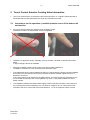
6 Frontline self-sufficient hobs
6.1
Special references disassembly/assembly in case of a service:
1. Disassemble appliance
Î Remove tension clips
2.
Open appliance
Î Attention! Before disassembling the glass draw off the connecting line between the user interface at the glass and
induction.
3. Replacement of display units
Î By means of a coin loosen plastic carriers by pressing and turning (29)
Î Shift back the plastic carrier until the front edge can be seen.
Î Lay plastic carrier to the bottom side
Î Remove locking bars like (30)
Î Draw off flat band cable
Î Replace electronic board
Î Assemble in the same way. Pay absolute attention to the correct putting and locking of the
band cable.
User interface and connection of two electronics at the glass ceramic (58 and 72 cm appliances)
(29)
(33) clamp bradings into the locking clips of the right carrier.
DGS-TDS
21.04.08
(33)
20
599 519 523 EN
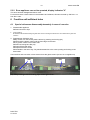
Assembly of band cable
(30)
Open locking (black bar)
(31)
Put band cable (silver contacts visible)
Close locking in arrow direction
(32)
Turn down the electronic with displays onto the glass side, press the carrier flatly to the glass lower side
and let it lock in. For assembly press the locking slightly to the bottom.
6.2
Demo mode / Self test
To enter the self-test/Demo mode, the following sequence of buttons must be pressed:
1. Hob is off. Press main switch continuously until display is going off.
2. Press the "+" and " -" buttons of the zones together (short beep) for about 3 seconds
DGS-TDS
21.04.08
21
599 519 523 EN
3. Then automatically the software version of the user interface is displayed,
for example „2“ „8“ = version 28 and all LEDs / Displays are ON for 10 Sec.
There is no alarm history mode available.
4. Demo mode
By pressing the button "A" / „P“ of one of the rear cooking zone you activate the demo mode, the
LED for Power function active is ON.
With activation of the demo mode the hob can be used like usual but without heater activation.
The deactivation of the demo mode is done in the same procedure as activating. The Led has to
be off.
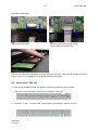
New Demo Mode/ Service Mode/ Alarm menu control philosophy starting with
October 2007 production
To access the self-test/demo mode, press the buttons in the following order:
1.
The cooking zone is switched off. Press the main switch until the display goes dark.
2.
Press the "+" and "-" buttons of the zones (short beep) simultaneously for about 3 seconds.
3.
After 3 seconds, a "d" for demo mode appears in the timer display or in the hot plate display
(depending on the model).
You can change between demo mode "d", service mode "S" and alarm menu "E" using the timer
button or "A" button (depending on the model). if you do not select anything, the unit will switch off.
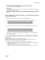
Demo Mode „d“
Activation: Press the "+" button of the left-hand cooking zone
Indication in the timer display or in the cooking zones display (depending on the model): "do"
You can use the unit as usual, but without heater activation.
To be able to use the unit normally, you have to carry out the following steps:
Repeat 1. to 3.; after 3 seconds, the timer display or the cooking zones display (depending on
the model) indicates a "do".
Deactivation: press the "+" button of the left-hand cooking zone
Indication in the timer display or in the cooking zones display (depending on the model): "d"
DGS-TDS
21.04.08