1
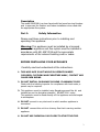
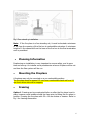
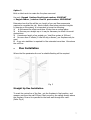
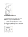
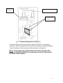
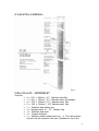
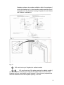
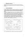
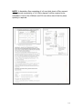
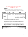
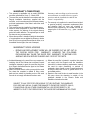
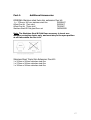
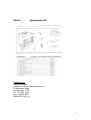
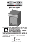
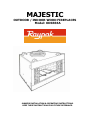
MAJESTIC
OUTDOOR / INDOOR WOOD FIREPLACES
Model: ODSR36A
OWNERS INSTALLATION & OPERATING INSTRUCTIONS.
KEEP THESE INSTRUCTIONS FOR FUTURE REFERANCE.
CONTENTS
Part 1:
Safety Information
Part 2:
Installation Instructions
•
•
•
•
•
•
•
•
•
•
•
Outdoor Installation
Planning Information
Mounting the Fireplace
Framing
Flue Installation
Flue Offset Installation
Positioning, safety Strips, Securing the fireplace
Chase Installation
Clearances
Sidewall Protection
Hearth Installations
Part 3:
Warranty
Part 4:
Additional Accessories
Part 5:
Spare Parts List
2
Description
The model ODSR36A is a clean faced solid fuel wood burning fireplace
and is approved for Outdoor and Indoor installation when used with
the appropriate flue system.
Part 1:
Safety Information
Please read these instructions prior to installing and
operating this appliance.
Warning: This appliance must be installed by a licensed
person. This appliance and flue system must be installed in
accordance with AS/ ANZ 2918 and the appropriate
requirements of the relevant building code or codes.
BEFORE INSTALLING YOUR APPLIANCE
Carefully read and understand all the instructions.
1. THIS APPLIACE IS HOT WHILE IN OPERATION KEEP
CHILDREN, CLOTHING AND FURNITURE AWAY, CONTACT MAY
CAUSE SKIN BURNS.
2. DO NOT INSTALL IN GARAGE OR NEAR FLAMMABLE FLUID
Check with the building inspector for compliance with local codes; a
permit may be required.
3. This appliance must be installed using Raypak approved flue kit and
installed as per the Australian standard AS/ANZ 2918 codes
This appliance must be flued directly off the appliance and discharged
to atmosphere.
4. DO NOT connect to any duct work to which another appliance is
connected.
5. DO NOT connect this unit to a chimney flue that is serving another
appliance.
6. DO NOT USE CHEMICALS OR FLUIDS TO START THE FIRE.
3
7. The flue should be inspected periodically and cleaned if necessary.
8. DO NOT store wood, flammable liquids or other combustible materials
close to the unit.
9. Contact your local fire authority for information on how to handle a
chimney fire. Have a clearly understood plan to handle a flue fire, turn
air control to the closed position and call the fire brigade.
10.DO NOT tamper with the combustion air control beyond the normal
adjustment.
11.DO NOT install combustible materials on the fire place surround.
This fire place is not designed to be a water tight fireplace. When
installing this unit against an external wall, the wall must be finished
before setting the unit in place.
12.Always leave the damper in the open position while the unit is in use
Once the required draw is obtained, close mesh screen to protect from
sparks that may occur.
13.DO NOT install these units into a mobile home or caravan. These units
are NOT mobile home approved.
Part 2:
Installation Instructions
• OUTDOOR INSTALLATION
Read this manual prior to beginning this installation and check
that you have been provided with the correct components
necessary to carry out the installation.
1
2
Remove all parts from inside the fire box.
Check outdoor flue kit part number: ODSSFLKT
Contents
• 1 x 203 x 1220 mm ( 8’) Inner stainless steel flue
• 1 x 279 x 1100 mm ( 11‘) Outer stainless steel flue
• 1 x Stainless Steel Cowl
• 1 x Powder coated vented dress ring . # This vented dress
ring will only be required to be used ( situated on top of the
fireplace enclosure to provide ventilation within the enclosure )
when the fireplace is in a free standing position and the flue is
4
exposed above the fireplace housing, this applies for both
Indoor and Outdoor installations
Note: If this unit is installed outdoors and the flue is to be
installed in a chase construction ( see Fig 6 ) or requires a
roof penetration ( pergola or veranda ) you must use the
Indoor flue kit part number: ODIDSSFLKT
Select the location for the appliance. This appliance must not be installed
inside minimum clearances to the house and any combustibles materials as
shown in Fig 1 & Fig 2
WARINING: FAILURE TO FOLLOW THE MINIMUM CLEARANCE
REQUIREMENTS MAY RESULT IN AN UNSAFE INSTALLATION.
Fig 1
Specifications & Framing layout
5
Fig 2 Free standing installation
Note: If the fire place is a free standing unit, it must be located a minimum
of 3m from the opening of the fire box to combustibles structure. A minimum
height of 1.9m measured from the base of the fire box to the flue termination
cowl is permitted.
•
Planning Information
Preplanning an installation is very important to ensure safety, and to save
time and money. An installer must predetermine where a fireplace will be set
and how the flue system will be run.
•
Mounting the Fireplace
A fireplace may only be mounted on a non combustible surface.
The fire place must be spaced 13 mm from a combustible back wall and 13
mm from either side wall or support.
•
Framing
Option 1 Framing can be constructed before or after the fire place is set in
place, however most installers build the frame prior to fitting the fire place in
position Framing the fire place with 50 x 100 mm timber or heavier. Refer to
Fig 1 for framing dimensions.
6
Option 2
Brick or block work to create the fire place surround.
Use only Raypak Outdoor flue kit part number: ODSSFLKT
or Raypak Indoor / outdoor flue kit part number: ODIDSSFLKT
Determine how the flue will be run, length of run and flue components
required to complete the job. Never install a flue below minimum heights.
In planning a flue system, it is important to know the following.
1
A flue cannot be offset more than 45 deg from a vertical plane.
2
A flue may run straight up or it may be necessary to offset it to avoid
obstructions.
3
A maximum length of an angled run ( total flue system is 500mm )
4
No more than 2 offsets (2 total 45 deg c elbows ) per fireplace may be
used.
5 A guy wire stabilizer is required for flue extended more than 1.8m above
the roof line.
•
Flue Installation
Where the flue penetrates the roof a suitable flashing will be required.
Fig 3
Straight Up flue Installation
To mark the centre line of the flue , put the fireplace in final position and
measure out from the wall 235mm. Mark a spot on the ceiling directly above
the fireplace. Draw a line parrallel to the back wall through this mark.
(Refer Fig 4)
7
Fig 4. Locate centreline of flue with plumb line.
•
Offset Installation
In order to clear an obstruction, it may be necessary to offset flue from
vertical. This is accomplished by using 2 x 45 deg ° offsets elbows.
Option 1: Twin skin Raypk Offset kit part number: DSSSOKT
Option 2: Triple skin Raypak Offset kit part number: TSSSOKT
•
Positioning, safety Strips, Securing the fireplace.
Slide the fire place into position. Four nailing flanges are incorporated on
each corner of the surround. Bend the nailing flanges out, level the box, then
secure it firmly in place by nailing the flanges to the framing members as
shown in.
Fig 14
Fig 5 Fasten fireplace into position
8
•
Chase Installation
A chase is a vertical boxlike structure which encloses the fireplace and flue.
Chases are typically built on the outside of the house or free standing with
fireplace opening cut into the outer wall of a room. (Fig 6) This structure with
the exception of 10 mm externally ventilated air gap (total area 9,268 mm2 )
around the 285 mm flue casing at the ceiling penetration
.
Fig 6
•
Fireplace and chase parts identification
Clearances
The following information provides minimum clearances that are required
when the installation is indoors or outdoors in a chase construction.
9
13 mm
Air space
40mm Air space required
13 mm Air space
to sides
Fig 7 Minimum clearances to combustibles
Fire stop (ceiling ring) must provide a minium of 9300mm2 of venting of
enclosure ( eg 10 mm gap around the outer flue casting at ceiling penetration
) where fireplace and flue casing are fully enclosed to ceiling level.
Note: The venting ring must be fitted in all cases when the flue
leaves the fireplace enclosure to ensure the correct air flow around
the case of the fire place.
10
A typical flue installation
Fig 8
Indoor Flue Kit - ODIDSSFLKT
Contents
•
•
•
•
•
•
•
•
•
4 x
1 x
4 x
2 x
1 x
1x
1x
2 x
1 x
ring
203 x 900mm ( 8” ) Stainless steel flue
203 x 150mm ( 8” ) Stainless steel flue adaptor
279 x 900mm ( 11”) Stainless steel flue
305 x 900mm ( 12”) Stainless steel flue
Stainless steel ceiling ring
Stainless steel 8” – 12 “ adaptor ring
Stainless steel cowl
Support brackets
Powder coated vented dress ring . # This vented dress
will only be required to be used ( situated on top of the
11
fireplace enclosure to provide ventilation within the enclosure )
when the fireplace is in a free standing position and the flue is
exposed above the fireplace housing, is applies for both Indoor
and Outdoor installations
Fig 9
Fig 10
305 mm from top of fireplace for radiant models
115 mm from top of fire place opening for radiant models (
non combustibles material must separate the black face surrounds of the
fireplace and any combustible mantel material ) the minimum perpendicular
side wall clearance from the fireplace opening 400 mm.
12
•
Side Wall Protection
Adjacent combustibles side walls that are within the minimum dimensions
(shown in Fig 11 of fireplace opening must be protected by a non combustible
materials.
•
Hearth installations
A hearth extension is required to protect a combustible floor in front of the
fireplace . refer Fig 13 for minimum dimensions and mounting details .Note
Hearth Extension must not cover the air inlet opening of the fire
place.
The hearth extension described in Fig 11 must be a durable non-combustible
material with a minimum ( total ) Rt valve of 1.09 refer to Fig 12 for
examples . The overall height ( above a combustible floor ) ,depth and width
must be indicated , with the extension centred to the fireplace opening.
The top of the installation must be covered with a non-combustible decorative
covering or a piece of 0.18” minimum sheet metal ,to protect hearth
extension material Fig 11 Secure the hearth extension to the floor to
prevent shifting , using trim moulding or other similar means at three ( 3 )
outer edges . Seal crack between the fireplace hearth and hearth extension
with a non-combustible material Fig 11 & Fig 13
Fig 11 Combustible side wall protection and hearth extension dimensions
13
NOTE: In Australia a floor consisting of a 6 mm thick sheet of fibre cement
with a thermal conductivity of 0.41 W/m degree K will be required to be
extended in front of the 4000mm and 200 mm either side of the fire place
opening is required.
Fig 12
Fig 13
14
Part 3:
Warranty
RAYPAK WOOD FIRE WARRANTY
- AUSTRALIA ONLY Rheem* will:
a) Repair or, if necessary replace any Raypak Wood Fire, or
b) Replace any component (or, if necessary, arrange the installation of a new wood fire ),
which falls within the Warranty Periods specified below, in accordance with and subject to
the following table, conditions and exclusions.
Installation
From date of installation
Model
Period
Warranty
ODSR36Al
Years 2
Raypak provide a warranty on any manufacture
part with a 1 year labour warranty .
Indoor or Outdoor
installation
Exclusion : If a glass weather proof Bi Fold door
is fitted it does have a limited warranty of 90 days
from the date of purchase.
Notes:
* Rheem provides warranty service on behalf of Raypak Australia Pty Ltd.
** Refer to item 5 of warranty conditions.
Rheem reserves the right to transfer fully functional components from the defective wood fire to
the replacement wood fire if required.
In addition to this warranty, the Trade Practices Act 1974 and similar laws in each state and
territory provide the owner under certain circumstances with certain minimum statutory rights in
relation to your Raypak wood fire. This warranty must be read subject to that legislation and
nothing in this warranty has the effect of excluding, restricting or modifying those rights.
RHEEM AUSTRALIA PTY LTD
A.B.N 21 098 823 511
RAYPAK AUSTRALIA PTY LTD
A.B.N 65 078 743 414
FOR SERVICE TELEPHONE
131 031 AUSTRALIA
0800 657 335 NEW ZEALAND
or refer local Yellow Pages
15
WARRANTY CONDITIONS
1. This warranty is applicable only to model ODSR36A
2.
3.
4.
5.
Insurance and travelling costs between the
nearest Rheem Accredited Service Agent’s
wood fire manufactured from 1st March 2005.
premises and the installed site shall be the
The wood fire must be installed in accordance with the
owner’s responsibility.
Raypak installation instructions, supplied with the
wood fire , and in accordance with all relevant statutory
6. The warranty only applies to the wood fire and original
and local requirements of the State in which the wood
or genuine (company) component replacement parts
fire is installed.
and therefore does not cover any plumbing or
This wood fire must be installed by a licensed person. .
electrical parts supplied by the installer and not an
Where a failed component or wood fire is replaced
integral part of the wood fire, e.g. ; glass weather
under warranty, the balance of the original warranty
doors.
period will remain effective. The replaced part or wood
fire does not carry a new warranty.
Where the wood fire is installed outside the boundaries
of a metropolitan area as defined by Rheem or further
than 25 km from a regional Rheem branch office, or an
Accredited Service Agent, the cost of transport,
WARRANTY EXCLUSIONS
1.
REPAIR AND REPLACEMENT WORK WILL BE CARRIED OUT AS SET OUT IN
THE RAYPAK WOOD FIRE WARRANTY, HOWEVER THE FOLLOWING
EXCLUSIONS MAY CAUSE THE WOOD FIRE WARRANTY TO BECOME VOID
AND MAY INCUR A SERVICE CHARGE AND / OR COST OF PARTS.
(a) Accidental damage to the wood fire or any component,
(c) Where the wood fire is located in a position that does
including: Acts of God; failure due to misuse; incorrect
not comply with the Raypak wood fire installation
installation; attempts to repair the wood fire other than
instructions or relevant statutory requirements, causing
by a Rheem Accredited Service Agent or the Rheem
the need for major dismantling or removal of
Service Department.
cupboards, doors or walls, or use of special equipment
to bring the wood fire to floor or ground level or to a
(b) Where it is found there is nothing wrong with the wood
serviceable position.
fire; where the complaint is related to fluing, water
leaks and are related to plumbing and not the wood (d) Repairs to the wood fire due to scale formation in the
fire and do not comply with relevant codes or acts.
flue ways where the chemistry is outside of the
guidelines detailed in the Owner’s Guide and
Installation Instructions booklet.
SUBJECT TO ANY STATUTORY PROVISIONS TO THE CONTRARY, THIS WARRANTY
EXCLUDES ANY AND ALL CLAIMS FOR DAMAGE TO FURNITURE, CARPETS, WALLS,
FOUNDATIONS OR ANY OTHER CONSEQUENTIAL LOSS EITHER DIRECTLY OR
INDIRECTLY DUE TO THE OPERATION OF THE WOOD FIRE WORKMANSHIP OR OTHER
.
16
Part 4:
Additional Accessories
ODSR36A Stainless steel twin skin extension flue kit:
1 x 279mm x 900 mm stainless steel flue
Offset Flue Kit (Twin skin)
Offset Flue Kit (Triple skin)
Stainless Steel Bi Fold glass Door set
DSSSEXKT
DSSSOKT
TSSSOKT
36GDKSSSR
Note: The Stainless Steel Bi Fold Door accessory is to act as a
weather protection device only, and must stay in the open position
at all times while the fire is lit.
Stainless Steel Triple Skin Extension Flue Kit:
1 x 203mm x 900mm stainless steel flue
1 x 279mm x 900mm stainless steel flue
1 x 305mm x 900mm stainless steel flue
17
Part 5:
Spare parts List
Distributed by:
Raypak Australia
( Division of Rheem Australia Pty Ltd )
39 Koornang Road
Scoresby Vic 3179
Ph 03 9757 3333
Fax 03 9757 3350
ABN 65078 743 414
18