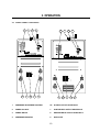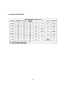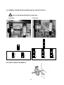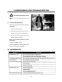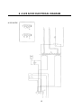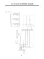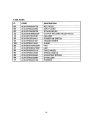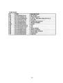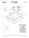
1
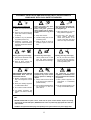
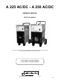
A 225 AC/DC - A 250 AC/DC
OWNER’S MANUAL
KEEP THIS MANUAL
The technical specifications and the wiring diagrams contained in this owner’s manual are valid only
for the model that has the part number indicated below.
A 225 AC/DC: ALW-M110500425
A 250 AC/DC: ALW-M110500426
Air Liquide Welding is a trademark of L’Air Liquide S.A.
08/01
TABLE OF CONTENTS
1
SAFETY PRECAUTIONS - READ BEFORE USING
1.1
1.2
1.3
1.4
1.5
1.6
1.7
1.8
1.9
1.10
2
SPECIFICATIONS AND DESCRIPTION
2.1
2.2
2.3
2.4
2.5
3
FRONT PANEL CONTROLS . . . . . . . . . . . . . . . . . . . . . . . . . . . . . . . . . . . . . . . . . . . . . . . .10
INSTALLATION
4.1
4.2
4.3
4.4
4.5
4.6
5
DESCRIPTION . . . . . . . . . . . . . . . . . . . . . . . . . . . . . . . . . . . . . . . . . . . . . . . . . . . . . . . . . . .7
SPECIFICATIONS . . . . . . . . . . . . . . . . . . . . . . . . . . . . . . . . . . . . . . . . . . . . . . . . . . . . . . . .7
COMES COMPLETE WITH . . . . . . . . . . . . . . . . . . . . . . . . . . . . . . . . . . . . . . . . . . . . . . . . .7
DUTY CYCLE AND OVERHEATING . . . . . . . . . . . . . . . . . . . . . . . . . . . . . . . . . . . . . . . . . . .8
VOLT-AMPERE CURVES . . . . . . . . . . . . . . . . . . . . . . . . . . . . . . . . . . . . . . . . . . . . . . . . . . .9
OPERATION
3.1
4
INSTALLATION OF EQUIPMENT . . . . . . . . . . . . . . . . . . . . . . . . . . . . . . . . . . . . . . . . . . . .3
PERSONAL PROTECTION . . . . . . . . . . . . . . . . . . . . . . . . . . . . . . . . . . . . . . . . . . . . . . . . .3
FIRE AND EXPLOSION PREVENTION . . . . . . . . . . . . . . . . . . . . . . . . . . . . . . . . . . . . . . . .4
METAL FUME HAZARDS . . . . . . . . . . . . . . . . . . . . . . . . . . . . . . . . . . . . . . . . . . . . . . . . . .4
TRANSPORTING THE POWER SOURCE . . . . . . . . . . . . . . . . . . . . . . . . . . . . . . . . . . . . . .5
MAGNETIC FIELDS CAN AFFECT PACEMAKERS . . . . . . . . . . . . . . . . . . . . . . . . . . . . . . .5
H.F. RADIATION CAN CAUSE INJURY . . . . . . . . . . . . . . . . . . . . . . . . . . . . . . . . . . . . . . . . .5
ARC WELDING CAN CAUSE INTERFERENCE . . . . . . . . . . . . . . . . . . . . . . . . . . . . . . . . . .5
WELDING AND THE EFFECTS OF LOW FREQUENCY AND MAGNETIC FIELDS . . . . . . .5
PRINCIPAL SAFETY STANDARDS . . . . . . . . . . . . . . . . . . . . . . . . . . . . . . . . . . . . . . . . . . .6
CONNECTING THE EQUIPMENT TO THE MAIN SUPPLY . . . . . . . . . . . . . . . . . . . . . . . .11
SELECTING A LOCATION . . . . . . . . . . . . . . . . . . . . . . . . . . . . . . . . . . . . . . . . . . . . . . . . .11
CONNECTION AND PREPARATION OF EQUIPMENT FOR STICK-ELECTRODE
WELDING . . . . . . . . . . . . . . . . . . . . . . . . . . . . . . . . . . . . . . . . . . . . . . . . . . . . . . . . . . . . .11
WELDING PARAMETERS . . . . . . . . . . . . . . . . . . . . . . . . . . . . . . . . . . . . . . . . . . . . . . . . .12
INTERNAL CONNECTION FOR OPERATING 230, 460 OR 575 VOLTS . . . . . . . . . . . . . . .13
HOW TO INSTALL THE WHEELS . . . . . . . . . . . . . . . . . . . . . . . . . . . . . . . . . . . . . . . . . . . .13
MAINTENANCE AND TROUBLESHOOTING
5.1
5.2
ROUTINE MAINTENANCE . . . . . . . . . . . . . . . . . . . . . . . . . . . . . . . . . . . . . . . . . . . . . . . . .14
TROUBLESHOOTING . . . . . . . . . . . . . . . . . . . . . . . . . . . . . . . . . . . . . . . . . . . . . . . . . . . .14
6
A 225 AC/DC ELECTRICAL DIAGRAM . . . . . . . . . . . . . . . . . . . . . . . . . . . . . . . . . . . . . .15
7
A 250 AC/DC ELECTRICAL DIAGRAM . . . . . . . . . . . . . . . . . . . . . . . . . . . . . . . . . . . . . .16
8
A 225 AC/DC SPARE PARTS LIST . . . . . . . . . . . . . . . . . . . . . . . . . . . . . . . . . . . . . . . . . .17
9
A 250 AC/DC SPARE PARTS LIST . . . . . . . . . . . . . . . . . . . . . . . . . . . . . . . . . . . . . . . . . .18
WARNING
Read and understand this entire Owner’s Manual before installing, operating or servicing this equipment. While the information contained in this Owner’s manual represents our best judgment, Air Liquide assumes no liability for its use.
Reproduction of this work, in whole or part, without written permission of the publisher is prohibited.
All rights reserved.
The publisher does not assume and hereby disclaims any liability to any party for any loss or damage caused by any error
or omission in the Air Liquide A 225 AC/DC – A 250 AC/DC Owner’s Manual, whether such error results from negligence, accident or any other causes.
1. SAFETY PRECAUTIONS - READ BEFORE USING
9 Avoid direct contact between wet garments and
metal parts that are electrically charged.
The use of welding equipment can cause
injury to the operator. The reading and understanding of the safety standards mentioned below is compulsory prior to connecting, preparing, using or
transporting welding equipment.
10. Always wear gloves and rubber-soled shoes
when working in wet areas or standing on
metal surfaces.
1.1 INSTALLATION OF EQUIPMENT
11. Always turn off welding equipment that is not
being used. Do not leave welding equipment
unattended.
1. Installation and maintenance of equipment
must be performed in compliance with local
safety standards.
2.
Significant DC voltage exists after the removal
of input power to inverters. Always discharge
input capacitors before touching any parts.
Service work should be completed by qualified personnel only.
Frequently inspect the welder plug,
receptacle and wiring. If damaged, replace
immediately with approved electrical connections and adequately sized wiring.
1.2 PERSONAL PROTECTION
3. Connect the welding ground as near as possible to the operating area.
1. Welding operations produce radiation, noise,
heat and noxious fumes. Suitable safety precautions must be taken to minimize the risk.
4. Do not pass welding equipment cables through
or near lifting chains, crane cables or any electrical lines.
2.
5. If earth grounding of the workpiece is required,
ground it directly with a separate cable.
6. Do not touch the electrode if you are in contact
with the work, ground or another electrode from
a different welding machine.
3.
7. Use only well-maintained equipment. Repair or
replace damaged parts immediately. Maintain
welding equipment according to owner’s manual.
Wear fire resistant work gloves, long
sleeve shirts, pants, safety shoes, cap and
welding helmet to protect the skin from radiation and metal sparks.
Always wear ear protection.
4. Always wear eye protection with side shields.
5. Position a fire resistant screen around the
welding area to protect bystanders from radiation, sparks and slag.
8. Never use welding equipment near water. Do
not spray water or other liquids on the welding
equipment.
3
6.
5. In the event that a welding operation occurs in
a confined place, the operator should be
accompanied by another person.
Compressed gas cylinders
are potentially dangerous. Consult the supplier
for correct handling procedures. Always protect
compressed gas cylinders from the sun’s rays,
flames and sudden temperature changes.
6. Always keep gas cylinders in a well-ventilated
area. Close the main gas valve when cylinder
is not in use.
7. Do not perform welding operations near chlorinated hydrocarbon vapors produced by
degreasing or painting. The heat generated by
arc rays can react to form phosgene, a highly
toxic gas.
1.3 FIRE AND EXPLOSION PREVENTION
Hot slag and sparks can
cause fire. The risk of fire and explosion can
be minimized by removing all flammable material from the welding area.
8. Irritation of the eyes, nose and throat are symptoms of inadequate ventilation. Take immediate
steps to improve ventilation. Do not continue
welding if symptoms persist.
1. Always perform welding operation with caution.
Containers and tubes that have been emptied
and thoroughly cleaned still represent a potential hazard.
1.5 TRANSPORTING THE POWER SOURCE
2. Never perform welding operations or cut a
closed container or pipe.
1. The welding machine may be carried by the
handle.
3. Never perform welding operations on open containers or pipes that may have been contaminated with substances that could explode or
react when exposed to heat or humidity.
2. Always disconnect the power source and
accessories from the main supply before lifting
or handling the welding equipment.
3. Do not drag, pull or lift welding equipment by
the weld cables.
4. As a preventative measure, keep fire extinguishers near the welding operation.
1.6 MAGNETIC FIELDS CAN AFFECT
PACEMAKERS
1.4 METAL FUME HAZARDS
Welding fumes and gases may be
hazardous if inhaled.
1.
1. Install a ventilation system in the welding area.
2. Pacemaker wearers should consult with a
physician prior to being exposed to any welding
or cutting operation.
2. Use a forced air system when welding lead,
beryllium, cadmium, zinc, zinc-coated or painted material. Always wear a protective mask.
3. If the ventilation system is inadequate, use an
air respirator.
4. Beware of gas leaks. Shielding gases such as
argon are heavier than air and when used in
small spaces, will replace the air.
4
Keep pacemaker wearers away from
welding operations.
1.9 WELDING AND THE EFFECTS OF LOW
FREQUENCY AND MAGNETIC FIELDS
1.7 H.F. RADIATION CAN CAUSE INJURY
1.
As welding current flows through welding cables, it
can cause electromagnetic fields. To reduce magnetic fields, use the following procedures:
High frequency (HF) emissions can
interfere with radio navigation, safety devices,
computers and communication equipment.
1 Keep cables close together by twisting or taping
them.
2. Installation of welding equipment should be
performed by a qualified electrician.
2. Arrange cables to one side and away from the
operator.
3. The operator is responsible for having a qualified electrician correct any interference problem
resulting from the welding equipment installation.
3. Do not coil or drape coils around operators
body.
4. If notified by the FCC about interference, stop
using the welding equipment immediately.
4. Keep welding power source and cables as far
away from the operator as practically possible.
5. Have the welding equipment installation
checked and maintained on a regular basis.
5. Connect work clamp to workpiece as close to
the weld as possible.
6. Keep high-frequency source doors and panels
tightly shut. Keep spark gaps at the correct setting and use grounding to minimize the possibility of interference.
1.8 ARC
WELDING
INTERFERENCE
1.
CAN
1.10 PRINCIPAL SAFETY STANDARDS
Safety in Welding and Cutting, ANSI Standard
Z49.1 from the American Welding Society, 550
N.W. Lejeune Rd., Miami, FL 33126.
CAUSE
Safety and Health Standards, OSHA 29 CFR
1910, from the Superintendent of Documents,
U.S. Government Printing Office, Washington,
D.C. 20402.
Electromagnetic energy can interfere
with sensitive electronic equipment such as
computers and computer-driven equipment like
robots.
2. Be sure that all equipment in the welding area
is electro-magnetically compatible.
Recommended Safe Practices for the Preparation
for Welding and Cutting of Containers That Have
Held Hazardous Substances, American Welding
Society Standard AWS F4.1, from the American
Welding Society, 550 N.W. Lejeune Rd., Miami, FL
33126.
3. To reduce possible interference, keep weld
cables as short as possible, close together and
down low.
National Electrical Code, NFPA Standard 70, from
the National Fire Protection Association,
Batterymarch Park, Quincy, MA 02269.
4. Locate welding operations at least 100 meters
(350 feet) away from any sensitive electronic
equipment.
Safe Handling of Compressed Gases in Cylinders,
CGA Pamphlet P-1, from the Compressed Gas
Association, 1235 Jefferson Davis Highway, Suite
501, Arlington, VA 22202.
5. Be sure welding equipment is installed and
grounded according to this manual.
Code for Safety in Welding and Cutting, CSA
Standard W117.2, from the Canadian Standards
Association, Standard Sales, 178 Rexdale
Boulevard, Rexdale, Ontario M9W 1R3.
6. If interference still occurs, the operator must
take extra measures such as moving the welding machine, using shielded cables, using line
filters, or shielding the work area.
Safe Practices For Occupation And Educational
Eye And Face Protection, ANSI Standards Z87.1
from the American National Standards Institute,
1430 Broadway, New York, NY 10018.
Cutting And Welding Processes, NFPA Standards
51B, from the National Fire Protection Association,
Batterymarch Park, Quincy, MA 02269.
5
EQUIPMENT INSTALLATION AND MAINTENANCE MUST BE PERFORMED IN
COMPLIANCE WITH LOCAL SAFETY STANDARDS.
Electric shock could be fatal
1. Never touch exposed electrical
parts.
2. Switch off and disconnect the
power source before installing
or opening.
Fumes and gases may represent a safety hazard.
Fumes and gases generated
during welding may be dangerous if inhaled over a long period
of time.
Use a protective mask with suitable glass filter (at least NR10)
to safeguard eyes.
1. Keep clear of fumes.
2. Protect face, ears and neck
during welding operations.
Advise other persons in the
vicinity to look away and stand
clear of arc rays and hot metal.
3. Installation may be performed
by qualified persons only.
2. Ventilate welding area or wear
a breathing mask.
4. Installation procedure must
comply with national electricity
standards and all other relevant
regulations.
3. Install a natural or forced air
ventilation system in the work
area.
Moving parts may cause injury.
Hot areas may cause injury.
1. Keep clear of hazardous areas,
such as moving rollers.
1. Beware of weld flame. Always
keep a fire extinguisher close at
hand.
2. Never place welding equipment
on inflammable surfaces.
3. Do not weld in closed containers.
Welding wire may cause injury.
Let the power source or other
parts cool before performing
any maintenance or servicing.
Do not point the torch toward
any part of the body, other persons or any type of metal when
unwinding welding wire.
A falling power source or other
equipment may cause serious
injury to persons or damage to
objects.
The positioning of welding
equipment on inflammable surfaces could lead to fire outbreak
or explosion.
1. Always make use of the handle
to lift power source (applies to
portable models).
1. Never position equipment on
combustible or inflammable
surfaces.
2. Use eye bolts and adequate lifting equipment to raise the
power source.
2. Do not install equipment in the
vicinity of inflammable liquids.
2. Keep all doors, panels and
covers closed and in place.
WELDING MAY CAUSE FIRES OR
EXPLOSIONS. Never weld near
inflammable materials.
1. Wear appropriate eye, ear and
body protection equipment.
4. Let welding equipment and
material cool before handling
them.
• INSTALLATION AND MAINTENANCE OPERATIONS MUST BE PERFORMED BY QUALIFIED PERSONS
ONLY.
• BEFORE INSTALLING the power source, check that the power socket satisfies ampere and voltage
requirements (see data table plate). ENSURE that the socket is protected by appropriate fuses and automatic switches.
• CONNECT an approved standard plug corresponding to the system socket to the power supply cable.
6
2. SPECIFICATIONS AND DESCRIPTION
2.1 DESCRIPTION
The 225 AC/DC sets a new standard for economical AC/DC arc welding machines. This ruggedlybuilt welder is a proven performer with serious
amperage to burn 2.5 mm (3/32 in) to 4.0 mm
(5/32 in) low-hydrogen and special-alloy electrodes.
A standard running gear improves mobility and
assists the operator in positioning the equipment
for those hard-to-reach areas. Standard dinse connections increase the versatily of the equipment
and make welding cable replacement an easy
task.
The 230/460 volt, 1-phase input power gives operators the option of choosing the power connections that are right for them. Infinte current regulation allows precise setting of amperage to achieve
the exact heat for your welding needs.
The 250 AC/DC sets a new standard for AC/DC
arc welding machines. This ruggedly-built welder
is a proven performer with serious amperage to
burn 2.5 mm (3/32 in) to 4.0 mm (5/32 in) low-hydrogen and special-alloy electrodes. A standard
running gear improves mobility and assists the
operator in positioning the equipment for those
hard-to-reach areas. Standard dinse connections
increase the versatily of the equipment and make
welding cable replacement an easy task.
The 230/460/575 volt, 1-phase input power gives
operators the option of choosing the power connections that are right for them. Infinite current regulation allows precise setting of amperage to
achieve the exact heat for your welding needs.
2.2 SPECIFICATIONS
A 225 AC/DC
A 250 AC/DC
2.3 COMES COMPLETE WITH:
A 225 AC/DC
A 250 AC/DC
1. 2.4 m (8 ft) input power cord without plug
2. Handle and running gear
1. Handle and running gear
For options and accessories contact your distributor.
7
2.4 DUTY CYCLE AND OVERHEATING:
Duty cycle is the percentage of 10 minutes that the
unit can weld at its rated output without overheating. If the unit overheats, the weld output will stop.
To correct this situation, wait fifteen minutes for the
unit to cool. Reduce amperage or duty cycle
before starting to weld again.
A 225 AC/DC DUTY CYCLE
OUTPUT AMPERES
OUTPUT
AMPERES
A 225 AC/DC
250
AC
200
150
100
DC
50
0
10
20
30
40
50
60
70
80
90
100
90
100
% DUTY CYCLE
A 250 AC/DC DUTY CYCLE
OUTPUT AMPERES
OUTPUT
AMPERES
A 250 AC/DC
300
250
AC
200
150
100
DC
50
0
10
20
30
40
50
60
% DUTY CYCLE
8
70
80
2.5 VOLT-AMPERE CURVES
Volt-ampere curves show the maximum voltage and amperage output capabilities of the welding power source.
Curves of other settings fall under curves shown.
A 225
A225 AC/DC
AC/DC
90
80
MAX DC
70
MAX AC
Voltage
(V)
Tensione (V)
60
50
MIN AC
40
30
20
MIN DC
10
0
0
20
40
60
80
100
120
140
160
180
200
220
240
260
280
300
200
220
240
260
280
300
Corrente (A)
Amperage
(A)
A 250
AC/DC
A250 AC/DC
90
80
70
MAX AC
Voltage
(V)
Tensione (V)
60
50
MAX DC
MIN AC
40
30
20
MIN DC
10
0
0
20
40
60
80
100
120
140
160
Corrente (A) (A)
Amperage
9
180
3. OPERATION
3.1 FRONT PANEL CONTROLS
4
6
1
5
3
9
2
7
4
8
6
1
5
3
9
2
7
8
1.
AMPERAGE ADJUSTMENT CONTROL
5/6. AC WELD OUTPUT RECEPTACLE
2.
POWER-ON LIGHT
7.
POSITIVE WELD OUTPUT RECEPTACLE
3.
POWER SWITCH
8.
NEGATIVE WELD OUTPUT RECEPTACLE
4.
AMPERAGE INDICATOR
9.
DATA PLATE
10
4. INSTALLATION
4. Avoid areas where dust or other objects could
be sucked into the system.
Before connecting, preparing or using
equipment, read Section 1: Safety Precautions.
5. Equipment must not obstruct corridors or work
activities of other personnel.
7. Position the power source securely to avoid
falling or overturning.
4.1 CONNECTING THE EQUIPMENT TO
THE MAIN SUPPLY
8. Understand the risk of falling equipment situated in overhead positions.
The equipment is shipped without an installed
plug.
For the A 225 AC/DC, use a plug that is suitable
for carrying the amps indicated on the data plate.
4.3 CONNECTION AND PREPARATION OF
EQUIPMENT FOR STICK-ELECTRODE
WELDING.
For the A 250 AC/DC, install a #8 or larger input
power cord to the internal connections indicated in
section 4.5. Use a plug that is suitable for carrying
the amps indicated on the data plate.
Connect all welding accessories carefully to
prevent power loss. Carefully follow safety precautions described in section 1.
Check to ensure that the power outlet is equipped
with a fuse that is capable of carrying the amps
indicated on the data plate of this unit.
TURN OFF WELDER BEFORE MAKING
CONNECTIONS.
DC MODE
4.2 SELECTING A LOCATION
1. Connect the ground cable to the negative
receptacle and locate the ground clamp near
the welding zone.
Special installation may be required
where gasoline or volatile liquids are present
(See NEC Article 511 or CEC Section 20). Do
not move or operate this equipment where it
could tip over. When selecting a location for
this equipment, ensure that the following
guidelines are followed.
2. Connect the electrode cable to the positive
receptacle and fit the selected welding electrode into the electrode holder.
3. Use the above connection for welding electrodes that use DCEP (Reverse Polarity) welding current. Reverse the connection for welding
electrodes that use DCEN (Straight Polarity)
welding current.
1. Use data plate to determine input power
requirements.
2. The operator must have unobstructed access to
all controls and equipment connections.
AC MODE
3. Do not position equipment in small, closed
places. Ventilation of the power source is
extremely important. Make sure that the louvers
on the side panels are not obstructed and that
there is no risk of obstruction during operation.
1. Connect the ground cable and the electrode
cable to the AC receptacles.
2. Fit the selected welding electrode into the electrode holder.
11
4.4 WELDING PARAMETERS
12
4.5 INTERNAL CONNECTION FOR INSTALLING 230, 460 OR 575 VOLTS
TURN OFF WELDER BEFORE MAKING CONNECTIONS.
A 250 AC/DC
230 V
460 V
230 V
4.6 HOW TO INSTALL THE WHEELS
13
460 V
575 V
L1 L2
GND
G 1 2 3 4 5 6 7 8 9
L1 L2
GND
G 1 2 3 4 5 6 7 8 9
L1 L2
GND
G 1 2 3 4 5 6 7 8 9
GND
G 1 2 3 4 5
GND
G 1 2 3 4 5
G 1 2 3 4 5
G 1 2 3 4 5 6 7 8 9
A 225 AC/DC
5. MAINTENANCE AND TROUBLESHOOTING
Disconnect power before maintenance.
Service more often during severe conditions.
5.1 ROUTINE MAINTENANCE
Every three (3) months, perform the operations below:
1. Replace unreadable labels
2. Clean and tighten weld terminal connections
3. Repair or replace worn hoses and cables
4. With dry compressed air, blow out the unit to
reduce the build-up of dust.
Every six (6) months perform the operations below:
Blow out the inside of the unit
Increase frequency of cleaning when operating in dirty or dusty conditions.
5.2 TROUBLESHOOTING
14
6. A 225 AC/DC ELECTRICAL DIAGRAM
A 225 AC/DC
15
7. A 250 AC/DC ELECTRICAL DIAGRAM
A 250 AC/DC
16
8. A 225 AC/DC SPARE PARTS LIST
17
18
9. A 250 AC/DC SPARE PARTS LIST
19
20