1
Installation and Operation
701-12442B
Manufactured in the USA by Audio Authority Corporation, Lexington Kentucky • 800-322-8346 or 859-233-4599 • www.audioauthority.com
Model 1173BK
Model 1173BK Multi-Zone Audio Router
Multi-Zone Audio Router with Volume Control
for the
HD Cat 5 Matrix Routing System
Audio Authority and the Double-A Symbol are registered trademarks of Audio Authority Corp.
AVAtrix and ExpressRamp are trademarks of Audio Authority. Copyright December, 2008, all rights reserved.
HDMI, the HDMI logo and High-Definition Multimedia Interface are trademarks or registered trademarks of
HDMI Licensing LLC.
Audio Authority® Corporation Lexington, Kentucky
www.audioauthority.com • 800-322-8346 • 859-233-4599
Warnings
To reduce the risk of fire or electric shock, do not expose this unit to rain or moisture.
!
•
•
•
•
•
•
•
2
The exclamation point symbol alerts users to important operating and
maintenance instructions in this booklet.
Read this manual before installing or using this product.
This product must be installed by qualified personnel.
Do not open the cover—there are no user-serviceable parts inside.
Do not expose this unit to excessive heat.
Install only in dry, indoor locations.
Do not obstruct the ventilation slots.
Clean the unit only with a dry or slightly dampened soft cloth.
Audio Authority Model 1173BK User Manual
•Connect associated equipment (see detailed instructions in the AVAtrix Manual).
•Connect the product to a suitable power outlet using only the power supply furnished.
•Update AVAtrix firmware to v1.4 or greater.
General Information
The Model 1173BK Multi-Zone Audio Router with Volume Control is a companion
product to the AVAtrix™ HD Cat 5 Routing System. It provides six analog or digital
audio source outputs to a distributed audio system to enable coordination of a room’s
audio program with the video program being received on a Cat 5 zone receiver. The
1173BK responds to IR or RS-232 commands from programmable control systems to
attenuate volume levels on individual analog outputs.
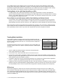
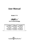
INFRARED
DATA INDICATOR LIGHT
•Read these instructions.
Model 1173BK Multi-Zone Audio Router
•Unpack the product and its accessories, and check to see all contents are included.
ADDRESS SWITCH
18 VOLT DC
In Tracking Mode, this switch
POWER
should match the 1176 switch
INPUT
setting; in Source mode, set to M
•Register your purchase at www.audioauthority.com/register to activate your warranty and for future upgrade notification. Write your registration password on the
back cover of these instructions.
701-12442B
Getting Started
Key Features
•Independently adjusts volume from 0 to -78dB in each zone (analog only)
INFRARED
OUTPUT
JACK
•Maximum configuration is six sources on 18 AVAtrix zones (Tracking Mode), or six
sources on 30 zones (Source Mode)
•IR routing for volume control and source control signals from zones
•18-volt power supply
•User manual
•Rack mounting adapters
Other Materials You May Need
•RCA patch cords
•IR emitters with 3.5mm plugs
•IR receivers (to connect to each Cat 5 zone receiver)
•Firmware upgrade for older AVAtrix installations
(download the upgrade from www.audioauthority.com/page/software)
Installation
These instructions address the Model 1173BK, which is always used with an
AVAtrix™ system. The system must include either a Model AVM-562 or Model
AVX‑562 with Cat 5 zone receivers, and can also include up to four Model 1176BK
matrix expanders. Refer to the AVAtrix instruction manual for complete installation
and setup directions.
* ExpressRamp™ enables a smooth volume change from the current level to a pre-defined level using a
single RS-232 command. It streamlines the programming of audio “scenes” on control systems and avoids
abrupt volume changes. ExpressRamp is not available using IR commands. See page 10 for details.
Manufactured in the USA by Audio Authority Corporation, Lexington Kentucky • 800-322-8346 or 859-233-4599 • www.audioauthority.com
•Model 1173BK Audio Router
Audio Authority Model 1173BK User Manual
DIGITAL AUDIO OUTPUT JACK
Carton Contents
LEFT/RIGHT ANALOG AUDIO OUTPUT
JACKS
•ExpressRamp™ zone volume control*
3
The 1173BK provides an audio breakout point to connect AVAtrix source audio to audio distribution equipment that
accepts stereo analog audio (for digital audio, see page 7). The analog outputs are volume controlled via commands
transmitted through the AVAtrix IR inputs or the RS-232 port. The 1173BK can be used in two different modes: Tracking
Mode or Source Mode, each designed to integrate with a different types of audio system, as follows:
Tracking Mode, for Use with Simple Amplifiers or AVRs
In Tracking Mode, each 1173BK output switches its content along with the AVAtrix so that the audio distribution
system’s output automatically matches what is playing on the video display in each room. Example: Zone 2 is viewing
Source 5 - the 1173BK outputs Source 5 audio from its Output 2. IR commands, including volume control, are routed
to the appropriate zone outputs and sources.
Source Mode, for an Audio System with its Own Switching and Volume Control
In Source Mode, each 1173BK output always provides the audio signal from its corresponding source input on the
AVAtrix (e.g. source 2 audio is always available on 1173BK output 2). The audio distribution system handles audio
signal switching and volume control for each zone. The 1173BK volume control is generally not used in Source Mode.
Both modes allow for infrared communication from the AVAtrix Cat 5 receivers in each room back to a distributed audio
system. AVAtrix IR codes are available at www.audioauthority.com/page/software, or from your remote control manufacturer. ExpressRamp volume control is only active when using RS-232 commands. See page 10 for details.
Tracking Mode Installation
Place a Model 1173BK in the AVAtrix equipment stack immediately beneath the
related Cat 5 output row. The diagram on the facing page shows a basic system (for
six zones), but an expanded system (for 12 or 18 zones) would be configured as
shown in the table.
The AVM-562 architecture allows up to five expanders. Using Tracking Mode, the
maximum number of Cat 5 zone outputs is 18 (shown) with three 1173BK expanders installed.
Model AVM-562
(Address A)
Model 1173BK
Address A
Model 1176BK
Address B
Model 1173BK
Address B
Model 1176BK
Address C
Model 1173BK
Address C
1. Set the 1173BK rotary address switches to match the corresponding Cat 5
matrix outputs (AVM-562 and 1176BK).
2. Connect the #1 Cat 5 output of the AVAtrix to the Cat 5 receiver in Zone 1.
3. Connect the #1 analog output of the Model 1173BK to the Zone 1 audio inputs of the amplifier or audio system (see
diagrams on pages 5 and 6). Digital Audio may be used where desired, but volume control must be performed by the
audio distribution system (see diagram on page 7).
4. If the AVAtrix system does not have current firmware (December 16 or later) then the firmware must be upgraded to
version 1.4 or greater. This upgrade allows the AVAtrix to control volume via the 1173BK.
5. Program the remote control system using AVAtrix IR codes, or RS-232 commands. To program IR remotes, download
AVAtrix IR codes from www.audioauthority.com/page/software or obtain the codes from your remote control manufacturer. ExpressRamp volume control is only active when using RS-232 commands (see page 10 for serial potocol).
IR Receivers
An IR receiver plugged into a dual Cat 5 zone receiver permits infrared commands to be sent to the 1176BK for A/V
source selection, to the AVAtrix A/V sources for source control, and to the 1173BK for volume control. The AVAtrix takes
care of routing the IR signals generated in each room to where they must go. The AVAtrix may be used with any of five
Cat 5 receiver styles. Models 9878 and 9879 and 9880 dual Cat 5 receivers feature an IR pathway and analog audio, and
1180R and 1180RD do not.
4
Audio Authority Model 1173BK User Manual
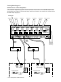
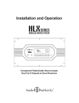
Tracking Mode Diagram 1:
Multi-Zone Amplifier
Tracking Mode is used with audio distribution systems having dedicated amplifiers for each room’s speakers. The amps
may be dedicated A/V receivers (see page 10) or a multi-zone amp, as shown below. The 1173BK audio output #1 tracks
with the AVAtrix Cat 5 output #1 so that the audio always matches the video at the zone. Address each 1173BK to match
the AVAtrix outputs (see page 4).
IR to Source 1
SOURCE 1
SOURCE 2
SOURCE 3
SOURCE 4
SOURCE 5
SOURCE 6
MAIN OUTPUT
AVM-562
1
2
1
3
2
4
3
5
4
AVM-562
(Address = A)
6
5
1173BK
A
6
Address = A
Variable
Audio
Output
Variable
Audio
Output
1
2
3
4
5
6
Speaker Wire
Multi-Zone
Amplifier
AC
Power
Strip
Cat 5
Cat 5
Zone 1
18V Power
Supplies to
Power Strip
Zone 3
Stereo Speakers
Stereo Speakers
IR Remote Control
IR Remote Control
IR
Receiver
9879
IR
Receiver
9879
Audio Authority Model 1173BK User Manual
5
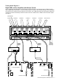
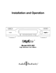
Tracking Mode Diagram 2:
A/V Receivers as Zone Amplifiers
In this configuration dedicated A/V receivers are used in place of a multi-zone amp. Here the 1173BK performs volume
control, whereas in diagram 3 IR signals are routed to each AVR to control volume. The 1173BK audio output #1 tracks
with the AVAtrix Cat 5 output #1 so that the audio always matches the video at the zone. Address each 1173BK to match
the AVAtrix outputs (see page 4).
IR to Source 1
SOURCE 1
SOURCE 2
SOURCE 3
SOURCE 4
SOURCE 5
SOURCE 6
MAIN OUTPUT
AVM-562
1
2
1
2
3
3
4
5
4
AVM-562
(Address = A)
6
5
1173BK
A
6
Address = A
Variable
Audio
Output
Variable
Audio
Output
18V Power
Supplies to
Power Strip
AVR 1
L R
AVR 3
L R
L R
Zone 3
Stereo Speakers
Stereo Speakers
IR Remote Control
IR Remote Control
IR
Receiver
6
Speaker Wire
Cat 5
Cat 5
Zone 1
L R
9879
Audio Authority Model 1173BK User Manual
IR
Receiver
9879
Tracking Mode Diagram 3:
Digital AVRs as Zone Amplifiers with Volume Control
In this configuration dedicated AVRs are used. Analog or digital audio may be connected from the 1173BK to the AVR
inputs. Digital output may be either 5.1 surround sound (e.g. zone 1 below), or two channel PCM (e.g. zone 3). IR signals
from each zone are routed to that zone’s AVR to control volume. The 1173BK audio output #1 tracks with the AVAtrix Cat
5 output #1 so that the audio always matches the video at the zone. Address each 1173BK to match the AVAtrix outputs
(see page 4).
IR to Source 1
SOURCE 1
SOURCE 2
SOURCE 3
SOURCE 4
SOURCE 5
SOURCE 6
MAIN OUTPUT
AVM-562
1
1
2
3
2
IR
3
Digital
Audio
4
5
4
IR
6
5
Address = A
Volume
Control
Signals
Volume
Control
Signals
IR
SUB L R
C
1173BK
A
6
Digital
Audio
DIGITAL
AVM-562
(Address = A)
DIGITAL
L R
AVR 1
18V Power
Supplies to
Power Strip
IR
L R
AVR 3
Cat 5
Speaker Wire
Zone 1
5.1 Channel Speakers
Cat 5
Speaker Wire
ax
Co
Zone 3
Stereo Speakers
9879
9879
IR Receiver
Sub
IR Remote Control
IR Remote Control
Audio Authority Model 1173BK User Manual
7
Source Mode Installation
In this mode the unswitched audio channels of the six AVAtrix system A/V sources
are provided as inputs to the audio distribution system. The Model 1173BK is therefore not associated with any one Model 1176BK, so only one 1173BK is necessary
even when there are multiple 1176BKs in the system as shown in the table.
The AVM-562 architecture allows up to five expanders. Using Source Mode, the
maximum number of Cat 5 zone outputs is 30 (shown) with one 1173BK installed.
Model AVM-562
(Address A)
Model 1176
Address B
Model 1176
Address C
Model 1176
Address D
Model 1176
Address E
Model 1173BK
Address M
1. Install the Model 1173BK anywhere in the AVAtrix stack and set its address dial
to the “M” position.
2. Connect the desired audio outputs, which represent the six AVAtrix A/V sources, to audio input channels on the audio
distribution system.
3. Audio system infrared outputs, if present, are intended to control its input sources. Plug a stick-on IR emitter into
each of the audio system’s IR output jacks and apply the emitter to the corresponding A/V source. In this way, source
control commands originating in each room are routed by the audio system via infrared to the relevant source. See
below for more information about using RF control systems.
IR Signal Routing
In Source Mode, the A/V sources and zone volume are generally controlled via IR through the audio distribution system
keypad / IR receiver in each zone. The AVAtrix IR commands must be routed through a separate IR receiver connected
to the AVAtrix Cat 5 receiver, necessitating two IR receivers in rooms with both A/V Cat 5 receivers and distributed audio
service. To program IR remotes, download AVAtrix IR codes from www.audioauthority.com/page/software or obtain the
codes from your remote control manufacturer. The AVAtrix may be used with any of five Cat 5 receiver styles. Models
9878 and 9879 and 9880 dual Cat 5 receivers feature an IR pathway and analog audio, and 1180R and 1180RD do not.
Using RF Control Systems
If desired, use the RS-232 connection for source switching and volume control, utilizing the 1173BK ExpressRamp volume
control (see page 10). The RF base station should generally be located near the AVAtrix. It may be to advantage to use
Model 1111 to inject IR commands from the RF base station zone outputs into the Cat 5 pathways to simplify programming. See Model 1111 manual for details.
Source Mode User Instructions
Depending on the installation, you will use a wall-mounted controller or an infrared or wireless controller to select which
music from various audio-only or audio/video sources you wish to enjoy. Your installer will have connected the AVAtrix
system and your whole-house or room audio system to work together, enabling you to bring the pictures and sound you
desire to each location in your home.
8
Audio Authority Model 1173BK User Manual
Source Mode Diagram
Integrated Audio Distribution System
Source mode is used with a whole-house audio system that includes its own switching and volume control. The 1173BK
audio output #1 always provides the audio from Source 1. 1173BK volume control is not generally used with this type of
system.
SOURCE 2
IR Signals from zone IR receiver to Source 1
SOURCE 1
1
SOURCE 3
2
SOURCE 4
3
SOURCE 5
4
5
SOURCE 6
6
MAIN OUTPUT
AVM-562
Address = A
1173
M
Address = M
Left / Right
Analog
Audio
Digital
Audio
(Optional)
Variable Audio Output
Audio Input for
Source 1
18V Power
Supplies to
Power Strip
Output to
Zone 1
IR Output to Source 1
Cat 5
Audio Distribution System
with Integrated Switching
Speaker Wire
Zone 1 Keypad
(Located in Equipment Closet)
Zone 1
Audio System
Keypad / IR
Receiver
IR
Receiver
Speakers
AVAtrix
Zone
Reciever
IR
Remote
Control
Note: In addition to the 2-channel audio
distribution, a digital home theater receiver
and speaker system may be connected to
the Cat 5 zone receiver if desired.
Audio Authority Model 1173BK User Manual
9
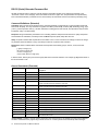
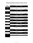
RS-232 (Serial) Extended Command Set
All valid commands receive a response, and all changes in the AVAtrix system via any method are reported. In the
“Command” column on the next page, actual commands are shown in upper case, and parameters are represented by
lower case bold characters (commands are not case-sensitive). All commands must be surrounded by brackets [ and ].
Command Definitions (Extended)
Command: String received by the AVAtrix from the controlling hardware. Commands are not case sensitive and should
be 8-bit with No parity. The only characters recognized are: letters (a-z and A-Z), numbers (0-9), brackets ([ and ]), signs
(+ and -), and the question mark (?) . All other characters, including spaces and commas, are optional and may be either
included for clarity or omitted entirely.
Response: String transmitted by the AVAtrix to the controlling hardware. Responses are 8-bit with no parity. Responses
are transmitted as noted below, and always have a C/R L/F sequence (0x0d, 0x0a) after each line.
Query: A special command that requests the current status of one or more connections or settings, but does not change
any operation within the AVAtrix. A query must always contain the ? question mark character.
Parameters: Values contained within commands and responses which identify groups, sources, zones, and router
devices.
j: group in range {1-6}
m: source in range {1-6}
n: zone in range {1-6}
x: A/V router device in range {A-F}
In this document, braces { and } are used to signify ONE of the enclosed characters. For example, {L,U} indicate either of
the two characters L or U.
General Commands (Extended)
Command:
Response:
[C,M,Im]
(M,Im)
Connect main output to source m
[C,Rx,On,Im]
(Rx,On,Im)
Connect zone n of A/V router x to source m
[C,X,Im]
(X,Im)
Connect all zones on all A/V routers to source m
[C,Gj,Im]
(Gj,Im)
Connect all outputs in group j to source m
[R,Rx,On,V]
(Rx,On,R,V,t)
Restrict video from A/V router x, zone n’s source from all other zones. t represents the
number of minutes left for this restriction. (see note)
[R,Rx,On,C]
(Rx,On,R,C,t)
Restrict control of A/V router x, zone n’s source from all other zones. t represents the
number of minutes left for this restriction.(see note)
[A,Rx,On]
(Rx,On,A)
Allow, A/V Router x, Zone n’s source to all zones.
Description:
[V,Rx,On,vvv]
(Rx,On,V,vvv)
Set volume level of zone n of 1173BK in tracking mode to volume vvv (ExpressRamp*)
[V,Im,vvv]
(Im,V,vvv)
Set volume level of source m (valid when 1173BK is in source mode)
[V,X,vvv]
(X,V,vvv)
Set volume level of all 1173BK’s in tracking mode to volume vvv (ExpressRamp*)
[L,P]
(P,L)
Lock out front panel controls
[U,P]
(P,U)
Unlock front panel controls
[L,I]
(I,L)
Lock out internal IR receiver
[U,I]
(I,U)
Unlock internal IR receiver
[+B]
(B,+)
Turn on display blanking
[-,B]
(B,-)
Turn off display blanking
[+P]
(P,+)
Select Professional Screen
[-,P]
(P,-)
Select Residential Screen
* ExpressRamp™ enables a smooth volume change from the current level to a pre-defined level using a single RS-232
command. It streamlines the programming of audio “scenes” on control systems and avoids abrupt volume changes.
10
Audio Authority Model 1173BK User Manual
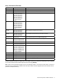
Query Commands (Extended)
Query:
Response:
Description:
[?,C,Rx,On]
(Rx,On,Im)
Query zone connection
[?,R,Rx,On]
(Rx,On,R,V,t)
Query zone restriction status. (see note)
[?,C,M]
(M,Im)
Query main connection
[?,C,X]
(RA,O1,Im) (RA,O2,Im)
(RA,O3,Im) (RA,O4,Im)
(RA,O5,Im) (RA,O6,Im)
(RB,O1,Im) (RB,O2,Im)
(RB,O3,Im) (RB,O4,Im)
(RB,O5,Im) (RB,O6,Im)
…through all devices
(M,Im)
Query all connections
[?,R,X]
(RA,O1,R,V,300) (RA,O2,Im)
(RA,O3,Im) (RA,O4,Im)
(RA,O5,Im) (RA,O6,Im)
(RB,O1,Im) (RB,O2,Im)
(RB,O3,Im) (RB,O4,Im)
(RB,O5,Im) (RB,O6,Im)
…through all devices
(M,Im)
Query restriction status of all zones (see note)
[?,C,RA]
(RA,O1,Im) (RA,O2,Im)
(RA,O3,Im) (RA,O4,Im)
(RA,O5,Im) (RA,O6,Im)
Query connections of all zones on A/V router x
[?,R,RA]
(RA,O1,R,V,300) (RA,O2,Im)
(RA,O3,Im) (RA,O4,Im)
(RA,O5,Im) (RA,O6,Im)
Query restriction status of all zones on A/V router x (see note)
[?,V,Rx,On,vvv]
(Rx,On,V,vvv)
Query volume level of zone n of 1173BK in tracking mode
[?,V,Rx]
(Rx,O1,V,vvv) (Rx,O2,V,vvv)
(Rx,O3,V,vvv) (Rx,O4,V,vvv)
(Rx,O5,V,vvv) (Rx,O6,V,vvv)
Query volume level of all zones of 1173BK tracking A/V router x
[?,V,Im]
(Im,V,vvv)
Query volume level of source m (valid when 1173BK is in source mode)
[?,V,I]
(I1,V,vvv) (I2,V,vvv) (I3,V,vvv)
(I4,V,vvv) (I5,V,vvv) (I6,V,vvv)
Query volume level of all sources (valid when 1173BK is in source mode)
[?,V,X]
(RA,O1,V,vvv) (RA,O2,V,vvv)
(RA,O3,V,vvv) (RA,O4,V,vvv)
(RA,O5,V,vvv) (RA,O6,V,vvv)
(RB,O1,V,vvv) (RB,O2,V,vvv)
(RB,O3,V,vvv) (RB,O4,V,vvv)
(RB,O5,V,vvv) (RB,O6,V,vvv)
…through all devices
Query volume level of all zones of all 1173’s in tracking mode
[?,{L,U},P]
(P,{L,U})
Query status of panel lockout
[?,{L,U},I]
(I,{L,U})
Query status of internal I/R lockout
[?,{L,U},A]
(A,{L,U})
Query status of AutoSelect lockout
[?,{+,-},B]
(B,{+,-})
Query status of Display blanking
[?,{+,-},P]
(P,{+,-})
Query status of Display Screen
All valid commands are listed in the tables above. If the AVAtrix receives any other string in brackets [ and ] it is identified
as an invalid command and the AVAtrix responds with the message (ERROR).
Note: When a zone is restricted, its input is set to a non-valid input number. If a user tries to restrict video or control of a
zone that is not on a valid input, the AVAtrix returns the input number to alert the programmer that the restriction was not
performed. Example: (Rx,On,I7).
Audio Authority Model 1173BK User Manual
11
Limited Warranty
If this product fails due to defects in materials or workmanship within one year from the date of the
original sale to the end-user, Audio Authority guarantees that we will replace the defective product
at no cost. Freight charges for the replacement unit will be paid by Audio Authority (Ground service
only). A copy of the invoice from an Authorized Reseller showing the item number and date of purchase (proof-of-purchase) must be submitted with the defective unit to constitute a valid in-warranty
claim.
Units that fail after the warranty period has expired may be returned to the factory for repair at a
nominal charge, if not damaged beyond the point of repair. All freight charges for out-of-warranty
returns for repair are the responsibility of the customer. Units returned for repair must have a Customer Return Authorization Number assigned by the factory.
This is a limited warranty and is not applicable for products which, in our opinion, have been damaged, altered, abused, misused, or improperly installed. Audio Authority makes no other warranties either expressed or implied, including limitation warranties as to merchantability or fitness for
a particular purpose. Additionally, there are no allowances or credits available for service work or
installation performed in the field by the end user.
2048 Mercer Road, Lexington, Kentucky 40511-1071
Phone: 859/233-4599 • Fax: 859/233-4510
Customer Toll-Free USA & Canada: 800/322-8346
Website: http://www.audioauthority.com
752-587
1/10