1
53-1000854-07
9 January 2015
Brocade 5100
Hardware Installation Guide
© 2015, Brocade Communications Systems, Inc. All Rights Reserved.
ADX, Brocade, Brocade Assurance, the B-wing symbol, DCX, Fabric OS, HyperEdge, ICX, MLX, MyBrocade, OpenScript, The Effortless
Network, VCS, VDX, Vplane, and Vyatta are registered trademarks, and Fabric Vision and vADX are trademarks of Brocade
Communications Systems, Inc., in the United States and/or in other countries. Other brands, products, or service names mentioned may be
trademarks of others.
Notice: This document is for informational purposes only and does not set forth any warranty, expressed or implied, concerning any
equipment, equipment feature, or service offered or to be offered by Brocade. Brocade reserves the right to make changes to this document
at any time, without notice, and assumes no responsibility for its use. This informational document describes features that may not be
currently available. Contact a Brocade sales office for information on feature and product availability. Export of technical data contained in
this document may require an export license from the United States government.
The authors and Brocade Communications Systems, Inc. assume no liability or responsibility to any person or entity with respect to the
accuracy of this document or any loss, cost, liability, or damages arising from the information contained herein or the computer programs that
accompany it.
The product described by this document may contain open source software covered by the GNU General Public License or other open
source license agreements. To find out which open source software is included in Brocade products, view the licensing terms applicable to
the open source software, and obtain a copy of the programming source code, please visit http://www.brocade.com/support/oscd.
Contents
Preface..................................................................................................................................... 5
Document conventions......................................................................................5
Text formatting conventions.................................................................. 5
Command syntax conventions.............................................................. 5
Notes, cautions, and warnings.............................................................. 6
Brocade resources............................................................................................ 7
Contacting Brocade Technical Support.............................................................7
Document feedback.......................................................................................... 8
About This Document................................................................................................................ 9
Supported hardware and software.................................................................... 9
What’s new in this document............................................................................ 9
Brocade 5100 Introduction .................................................................................................... 11
Brocade 5100 overview...................................................................................11
Facility requirements....................................................................................... 12
Port side of the Brocade 5100.........................................................................13
Port Numbering................................................................................... 13
Non-port side of the Brocade 5100................................................................. 14
Field replaceable units (FRUs)........................................................................14
Ports on Demand license................................................................................ 15
ISL trunking groups......................................................................................... 15
Brocade 5100 Installation and Configuration.......................................................................... 17
Installation and safety considerations............................................................. 17
General precautions............................................................................17
ESD precautions................................................................................. 17
Power precautions.............................................................................. 18
RTC battery precautions..................................................................... 18
Environmental considerations............................................................. 19
EIA rack considerations...................................................................... 19
Recommendations for cable management......................................... 20
Items required for installation.............................................................. 20
Items included with the Brocade 5100............................................................ 20
Installing a standalone Brocade 5100............................................................. 21
Rack installation for a Brocade 5100.............................................................. 21
Brocade 5100 configuration............................................................................ 22
Providing power to the switch............................................................. 22
Creating a serial connection................................................................22
Switch IP address............................................................................... 23
Date and time settings........................................................................ 24
Brocade 5100 Operation........................................................................................................ 27
Powering the Brocade 5100 on and off...........................................................27
LED activity interpretation............................................................................... 27
Brocade 5100 LEDs............................................................................ 27
Brocade 5100 Hardware Installation Guide
53-1000854-07
3
LED locations....................................................................................28
LED Patterns.....................................................................................28
POST and boot specifications.......................................................................30
POST................................................................................................ 30
Boot...................................................................................................31
Interpreting POST results..............................................................................31
Maintaining the Brocade 5100...................................................................... 31
Installing an SFP............................................................................... 32
Diagnostic tests.................................................................................32
Field Replaceable Units (FRUs)........................................................33
Power supply/fan assembly FRU replacement................................. 33
Managing the Brocade 5100.........................................................................34
Removal and Replacement of Combined Power Supply and Fan Assembly (Port-side Air
Exhaust).......................................................................................................................... 35
Before beginning installation.........................................................................35
Installing a combined power supply and fan assembly FRU........................ 35
Time required.................................................................................... 36
Items required................................................................................... 36
Replacing the power supply/fan assembly........................................36
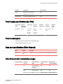
Brocade 5100 Technical Specifications................................................................................ 39
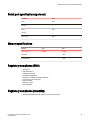
Regulatory Statements..........................................................................................................45
BSMI statement (Taiwan)..............................................................................45
Canadian requirements.................................................................................45
CE Statement................................................................................................45
China CC statement......................................................................................46
China ROHS................................................................................................. 46
FCC warning (US only)................................................................................. 47
KCC statement (Republic of Korea)..............................................................47
VCCI statement.............................................................................................47
Cautions and Danger Notices................................................................................................ 49
Cautions........................................................................................................49
Danger Notices............................................................................................. 52
Index.................................................................................................................................... 55
4
Brocade 5100 Hardware Installation Guide
53-1000854-07
Preface
● Document conventions......................................................................................................5
● Brocade resources............................................................................................................ 7
● Contacting Brocade Technical Support.............................................................................7
● Document feedback.......................................................................................................... 8
Document conventions
The document conventions describe text formatting conventions, command syntax conventions, and
important notice formats used in Brocade technical documentation.
Text formatting conventions
Text formatting conventions such as boldface, italic, or Courier font may be used in the flow of the text
to highlight specific words or phrases.
Format
Description
bold text
Identifies command names
Identifies keywords and operands
Identifies the names of user-manipulated GUI elements
Identifies text to enter at the GUI
italic text
Identifies emphasis
Identifies variables and modifiers
Identifies paths and Internet addresses
Identifies document titles
Courier font
Identifies CLI output
Identifies command syntax examples
Command syntax conventions
Bold and italic text identify command syntax components. Delimiters and operators define groupings of
parameters and their logical relationships.
Convention
Description
bold text
Identifies command names, keywords, and command options.
italic text
Identifies a variable.
Brocade 5100 Hardware Installation Guide
53-1000854-07
5
Notes, cautions, and warnings
Convention
Description
value
In Fibre Channel products, a fixed value provided as input to a command
option is printed in plain text, for example, --show WWN.
[]
Syntax components displayed within square brackets are optional.
Default responses to system prompts are enclosed in square brackets.
{x|y|z}
A choice of required parameters is enclosed in curly brackets separated by
vertical bars. You must select one of the options.
In Fibre Channel products, square brackets may be used instead for this
purpose.
x|y
A vertical bar separates mutually exclusive elements.
<>
Nonprinting characters, for example, passwords, are enclosed in angle
brackets.
...
Repeat the previous element, for example, member[member...].
\
Indicates a “soft” line break in command examples. If a backslash separates
two lines of a command input, enter the entire command at the prompt without
the backslash.
Notes, cautions, and warnings
Notes, cautions, and warning statements may be used in this document. They are listed in the order of
increasing severity of potential hazards.
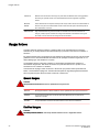
NOTE
A Note provides a tip, guidance, or advice, emphasizes important information, or provides a reference
to related information.
ATTENTION
An Attention statement indicates a stronger note, for example, to alert you when traffic might be
interrupted or the device might reboot.
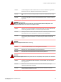
CAUTION
A Caution statement alerts you to situations that can be potentially hazardous to you or cause
damage to hardware, firmware, software, or data.
DANGER
A Danger statement indicates conditions or situations that can be potentially lethal or
extremely hazardous to you. Safety labels are also attached directly to products to warn of
these conditions or situations.
6
Brocade 5100 Hardware Installation Guide
53-1000854-07
Brocade resources
Brocade resources
Visit the Brocade website to locate related documentation for your product and additional Brocade
resources.
You can download additional publications supporting your product at www.brocade.com. Select the
Brocade Products tab to locate your product, then click the Brocade product name or image to open the
individual product page. The user manuals are available in the resources module at the bottom of the
page under the Documentation category.
To get up-to-the-minute information on Brocade products and resources, go to MyBrocade. You can
register at no cost to obtain a user ID and password.
Release notes are available on MyBrocade under Product Downloads.
White papers, online demonstrations, and data sheets are available through the Brocade website.
Contacting Brocade Technical Support
As a Brocade customer, you can contact Brocade Technical Support 24x7 online, by telephone, or by email. Brocade OEM customers contact their OEM/Solutions provider.
Brocade customers
For product support information and the latest information on contacting the Technical Assistance
Center, go to http://www.brocade.com/services-support/index.html.
If you have purchased Brocade product support directly from Brocade, use one of the following methods
to contact the Brocade Technical Assistance Center 24x7.
Online
Telephone
E-mail
Preferred method of contact for nonurgent issues:
Required for Sev 1-Critical and Sev
2-High issues:
[email protected]
• My Cases through MyBrocade
•
Continental US: 1-800-752-8061
• Software downloads and licensing •
tools
Europe, Middle East, Africa, and
Asia Pacific: +800-AT FIBREE
(+800 28 34 27 33)
• Knowledge Base
•
For areas unable to access toll
free number: +1-408-333-6061
•
Toll-free numbers are available in
many countries.
Please include:
•
Problem summary
•
Serial number
•
Installation details
•
Environment description
Brocade OEM customers
If you have purchased Brocade product support from a Brocade OEM/Solution Provider, contact your
OEM/Solution Provider for all of your product support needs.
• OEM/Solution Providers are trained and certified by Brocade to support Brocade® products.
• Brocade provides backline support for issues that cannot be resolved by the OEM/Solution Provider.
Brocade 5100 Hardware Installation Guide
53-1000854-07
7
Document feedback
• Brocade Supplemental Support augments your existing OEM support contract, providing direct
access to Brocade expertise. For more information, contact Brocade or your OEM.
• For questions regarding service levels and response times, contact your OEM/Solution Provider.
Document feedback
To send feedback and report errors in the documentation you can use the feedback form posted with
the document or you can e-mail the documentation team.
Quality is our first concern at Brocade and we have made every effort to ensure the accuracy and
completeness of this document. However, if you find an error or an omission, or you think that a topic
needs further development, we want to hear from you. You can provide feedback in two ways:
• Through the online feedback form in the HTML documents posted on www.brocade.com.
• By sending your feedback to [email protected].
Provide the publication title, part number, and as much detail as possible, including the topic heading
and page number if applicable, as well as your suggestions for improvement.
8
Brocade 5100 Hardware Installation Guide
53-1000854-07
About This Document
● Supported hardware and software.................................................................................... 9
● What’s new in this document............................................................................................ 9
Supported hardware and software
Although many different software and hardware configurations are tested and supported by Brocade
Communications Systems, Inc. for Fabric OS v6.1.0, documenting all possible configurations and
scenarios is beyond the scope of this document.
This document is specific to the Brocade 5100 and Fabric OS v6.1.0. To obtain information about a
Fabric OS version other than v6.1.0, see the documentation specific to that OS version.
What’s new in this document
• An illustration indicating the port numbers and the port groups is added.
• A chapter on removal and replacement of power supplies and fan assemblies is added.
• All references to EIA cabinet have been changed to EIA rack since closed cabinets are not supported
by Brocade products.
• The regulatory compliance statements are moved to a new chapter/appendix.
‐
China CCC certification has been updated from “GB17625.1-2003 or latest” to
“GB17625.1-2012 or latest”.
‐
Laser compliance statement is removed.
‐
The Japan VCCI statement has been updated.
‐
China RoHS compliance statements are removed and a reference to the latest independent
China RoHS compliance document is added.
• A new chapter/appendix on cautions and danger notices is added with translation in multiple
languages.
Brocade 5100 Hardware Installation Guide
53-1000854-07
9
What’s new in this document
10
Brocade 5100 Hardware Installation Guide
53-1000854-07
Brocade 5100 Introduction
● Brocade 5100 overview...................................................................................................11
● Facility requirements....................................................................................................... 12
● Port side of the Brocade 5100.........................................................................................13
● Non-port side of the Brocade 5100................................................................................. 14
● Field replaceable units (FRUs)........................................................................................14
● Ports on Demand license................................................................................................ 15
● ISL trunking groups......................................................................................................... 15
Brocade 5100 overview
The Brocade 5100 is an Enterprise class 1U, 40-port Fibre Channel 1, 2, 4 or 8 Gbps Fibre Channel
switch that offers the next generation Brocade, single-chip architecture for Storage Area Networks
(SANs). The Brocade 5100 is designed to function in large-scale enterprise SANs and can also fit the
requirements of small to medium-sized work groups.
Because the Brocade 5100 has a slim 1U height and a high port count, you can use the Brocade 5100
to create very dense fabrics in a relatively small space. With its flexible Ports On Demand (POD)
capability, the Brocade 5100 provides excellent overall value as the foundation of a SAN with the ability
to grow with an organization’s SAN needs.
The Brocade 5100 is the latest mid-range offer from the Brocade family of entry-to-enterprise products.
It supports the following features:
•
•
•
•
•
•
•
•
•
•
•
•
Up to 40 ports of high-performance 8 Gbps technology and POD scaling from 24 to 32 or 40 ports.
Support for 1, 2, 4, and 8 Gbps auto-sensing Fibre Channel switch and router ports.
FICON®, FICON Cascading and FICON Control Unit Port ready.
Two hot-swappable, redundant integrated power supply and fan FRUs.
Universal ports that self-configure as E, F, M, or FL ports. Ex_Ports are activated on a per port basis
with the optional Integrated Routing license.
Fibre Channel Routing (FCR) service that provides improved scalability and fault isolation (through
the optional Integrated Routing license).
An RJ45 Ethernet management port, that in conjunction with EZSwitchSetup, supports switch IP
address discovery and configuration, eliminating the need to attach a serial cable to configure the
switch IP address and greatly increasing the ease of use.
USB port that provides storage for firmware updates, output of the supportSave command and
storage for configuration uploads and downloads
Single motherboard design with 667 MHz PowerPC 440EPx Reduced Instruction Set Computer
(RISC) CPU and integrated peripherals which provide high performance.
Inter-Switch Link (ISL) Trunking (licensable), which allows up to eight ports (at 1, 2, 4, or 8 Gbps
speeds) between a pair of switches combined to form a single, logical ISL with a speed of up to 128
Gbps full duplex for optimal bandwidth utilization and load balancing.
Dynamic Path Selection (DPS), which optimizes fabric-wide performance and load balancing by
automatically routing data to the most efficient available path in the fabric.
Rack-mount design using existing rail kits (fixed, sliding, and mid-mount/Telco rail kits) on a 19" EIA
rack.
Brocade 5100 Hardware Installation Guide
53-1000854-07
11
Facility requirements
• Industry-leading extended distance support, which enables native Fibre Channel extension greater
than 590 km.
• Expanded security for up to 16,000 hardware zones. Hardware zoning is accomplished at the port
level of the switch or by World Wide Name (WWN). Hardware zoning permits or denies delivery of
frames to any destination port address.
• Unicast, multicast (255 groups), and broadcast data traffic type, are support.
• Brocade Small Form-Factor Pluggable (SFP) or SFP+ optical transceivers support any combination
of Short Wavelength (SWL), Long Wavelength (LWL) or Extended Long Wavelength (ELWL) optical
media among the switch ports.
• Brocade Fabric Operating System (Fabric OS), which delivers distributed intelligence throughout
the network and enables a wide range of value-added applications including Brocade Advanced
Web Tools and Brocade Zoning. Optional Fabric Services include: Adaptive Networking with QoS,
Brocade Extended Fabrics, Brocade Enhanced Group Management, Brocade Fabric Watch, ISL
Trunking, Integrated Routing, and End-to-End Performance Monitoring (APM).
• Port-to-port latency minimized to 700 nanoseconds through the use of cut-through frame routing at
8 Gbps.
• Extensive diagnostics and system monitoring capabilities, which enhance high Reliability,
Availability, and Serviceability (RAS).
• The Brocade EZSwitchSetup wizard, which makes SAN configuration a three-step point-and click
task.
Facility requirements
The following table provides the facilities requirements that must be met for the Brocade 5100.
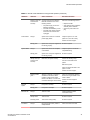
TABLE 1 Facility Requirements
Type
Requirements
Electrical
•
Primary AC input 100-240 VAC, 2.0A, 47-63 Hz; switch autosenses input voltage
•
Adequate supply circuit, line fusing, and wire size, as specified by the electrical rating on the
switch nameplate
•
Circuit protected by a circuit breaker and grounded in accordance with local electrical codes
Refer to GUID-2965C97E-D67D-4F0A-8461-4C96C8CB0654#GUID-2965C97ED67D-4F0A-8461-4C96C8CB0654 for complete power supply specifications.
Thermal
Rack (when
rackmounted)
12
•
A minimum air flow of 79.8 cubic meters/hour (47 cubic ft/min.) available in the immediate
vicinity of the switch
•
Ambient air temperature not exceeding 40 ° C (104 ° F) while the switch is operating
• One rack unit (1U) in a 48.3 cm (19-inch) rack
• All equipment in rack grounded through a reliable branch circuit connection
•
Additional weight of switch not to exceed the rack’s weight limits
•
Rack secured to ensure stability in case of unexpected movement
Brocade 5100 Hardware Installation Guide
53-1000854-07
Port side of the Brocade 5100
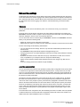
Port side of the Brocade 5100
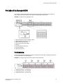
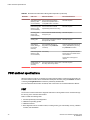
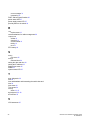
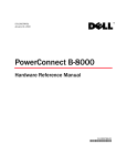
The port side of the Brocade 5100 includes the system status LED, console port, Ethernet port and
LEDs, USB port, and Fibre Channel ports and the corresponding port status LEDs.
FIGURE 1 Port-side view of the Brocade 5100
1.
2.
3.
4.
5.
6.
7.
8.
System status (top) and power (bottom) LEDs
System RS232 console port (RJ-45)
System Ethernet port (RJ-45)
Ethernet port LEDs (green/amber)
USB port
Fibre Channel port status LED
Fibre Channel ports
Switch ID pull-out tab
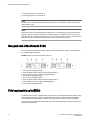
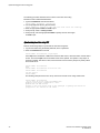
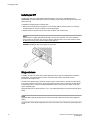
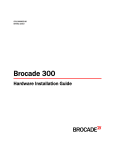
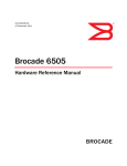
Port Numbering
The Fibre Channel ports on the Brocade 5100 are numbered from left to right, in eight-port groups from
0 to 39 as illustrated in the following figure.
FIGURE 2 Trunking port groups and port numbers of the Brocade 5100
1. Trunking port group 1; FC ports 00-07
2. Trunking port group 1; FC ports 08-15
3. Trunking port group 1; FC ports 16-23
Brocade 5100 Hardware Installation Guide
53-1000854-07
13
Non-port side of the Brocade 5100
4. Trunking port group 1; FC ports 24-31
5. Trunking port group 1; FC ports 32-39
NOTE
You can also use port index and PIDs to identify a port. For more information, refer to the Fabric OS
Administrator's Guide
NOTE
Brocade ISL Trunking is licensed software that allows you to create trunking groups of ISLs between
adjacent switches. Trunking is supported by combining maximum of eight ports per group to form 64Gbps ISL trunk. The trunking port groups are 0-7, 8-15, 16-23, 24-31, and 32-39. For more information
about Brocade ISL Trunking, refer to the Brocade Fabric OS Administrator’s Guide.
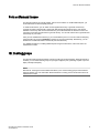
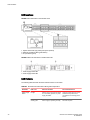
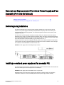
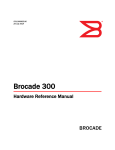
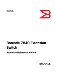
Non-port side of the Brocade 5100
The non-port side of the Brocade 5100 includes the two redundant power supply-fan assemblies and
the corresponding status LEDs.
FIGURE 3 Non-port side view of the Brocade 5100
1.
2.
3.
4.
5.
6.
7.
8.
Fan (for power supply/fan FRU2)
Power supply/Fan status LED (for power supply/fan FRU 2)
Power supply connector (for power supply/fan FRU2)
Fan (for power supply/fan FRU2)
Fan (for power supply/fan FRU1)
Power supply/Fan status LED (for Power Supply/fan FRU 1)
Power supply connector (for power supply/fan FRU 1)
Fan (for power supply/fan FRU1)
Field replaceable units (FRUs)
The Brocade 5100 has two integrated power supply and fan unit field replaceable units (FRUs). These
power supply/fan assembly units are hot-swappable and redundant, and are capable of functioning
universally without voltage jumpers or switches. The FRU units are identical and interchangeable.
The front panel has a status LED that provides the status of the entire switch, including the two power
supply/fan assembly FRUs.
14
Brocade 5100 Hardware Installation Guide
53-1000854-07
Ports on Demand license
Ports on Demand license
The Brocade 5100 has 40 ports. By default, ports 0-24 are enabled. To enable additional ports, you
must install Ports On Demand (POD) licenses.
To install a POD license, you can either use the supplied license key or generate a license key.
Typically the switch is shipped with a paper pack that specifies the transaction key to use with the
Software License Keys link. Use this transaction key on the Brocade Web site at www.brocade.com /
licensekeys and follow the instructions to generate the key. You can also use this site to generate other
license keys for your switch.
After you have installed the license keys, you must enable the ports. You can do so without disrupting
switch operation by using the portEnable command on each port individually. Alternatively, you can
disable and re-enable the switch to activate all ports simultaneously.
For detailed information on enabling additional ports using the POD license, refer to the Fabric OS
Administrator’s Guide
ISL trunking groups
The Brocade 5100 supports Interswitch Link (ISL) Trunking as a licensed feature. When this feature is
enabled, you can create trunked groups of up to eight contiguous ports, permitting a speed of up to 64
Gbps (128 Gbps full duplex).
NOTE
Brocade ISL Trunking is licensed software that allows you to create trunking groups of ISLs between
adjacent switches. For more information about Brocade ISL Trunking, refer to the Brocade Fabric OS
Administrator’s Guide
Brocade 5100 Hardware Installation Guide
53-1000854-07
15
ISL trunking groups
16
Brocade 5100 Hardware Installation Guide
53-1000854-07
Brocade 5100 Installation and Configuration
● Installation and safety considerations............................................................................. 17
● Items included with the Brocade 5100............................................................................ 20
● Installing a standalone Brocade 5100............................................................................. 21
● Rack installation for a Brocade 5100.............................................................................. 21
● Brocade 5100 configuration............................................................................................ 22
Installation and safety considerations
You can install the Brocade 5100 switch in the following ways:
1. As a standalone unit on a flat surface.
2. In an EIA rack using a fixed-rail rack mount kit. The optional fixed-rail rack mount kit can be ordered
from your switch retailer.
3. In an EIA rack using an optional slide-rail rack mount kit. The optional slide-rail rack mount kit can be
ordered from your switch retailer. When mounting into a slide-rail rack, you can mount the chassis to
slide from either the port side or the non-port side.
4. In an EIA rack using an optional mid-mount rack kit for switches. The optional mid-mount rack kit for
switches can be ordered from your switch retailer.
General precautions
When using this product, observe all danger, caution, and attention notices in this manual. The notices
are accompanied by symbols that represent the severity of the safety condition.
NOTE
Refer to Cautions and Danger Notices on page 49 for translations of safety notices for this product.
DANGER
The procedures in this manual are for qualified service personnel.
CAUTION
Changes or modifications made to this device that are not expressly approved by the party
responsible for compliance could void the user's authority to operate the equipment.
ESD precautions
This product contains electrostatic discharge (ESD) sensitive field-replacable units (FRUs) When
working with any FRU, use correct ESD procedures.
Brocade 5100 Hardware Installation Guide
53-1000854-07
17
Power precautions
CAUTION
Before plugging a cable into to any port, be sure to discharge the voltage stored on the cable
by touching the electrical contacts to ground surface.
CAUTION
Static electricity can damage the chassis and other electronic devices. To avoid damage, keep
static-sensitive devices in their static-protective packages until you are ready to install them.
Wear a wrist grounding strap connected to chassis ground (if the device is plugged in) or a bench
ground.
DANGER
For safety reasons, the ESD wrist strap should contain a series 1 megaohm resistor.
Power precautions
To install and operate the switch successfully, ensure the following:
• The primary outlet is correctly wired, protected by a circuit breaker, and grounded in accordance
with local electrical codes.
DANGER
Make sure that the power source circuits are properly grounded, then use the power cord
supplied with the device to connect it to the power source.
• The supply circuit, line fusing, and wire size are adequate, as specified by the electrical rating on
the switch nameplate.
• This switch might have more than one power cord. To reduce the risk of electric shock, disconnect
both power cords before servicing.
DANGER
Remove both power cords before servicing.
DANGER
Disconnect the power cord from all power sources to completely remove power from the
device.
• This product is designed for an IT power system with phase-to-phase voltage of 230V. After
operation of the protective device, the equipment is still under voltage if it is connected to an IT
power system.
DANGER
To avoid high voltage shock, do not open the device while the power is on.
• The power supply standards provided in "Power Supply Specifications" are met.
RTC battery precautions
Do not attempt to replace the real-time clock (RTC) battery. There is danger of explosion if the battery
is incorrectly replaced or disposed of. Contact your switch supplier if the real-time clock begins to lose
time.
18
Brocade 5100 Hardware Installation Guide
53-1000854-07
Environmental considerations
DANGER
Risk of explosion if battery is replaced by an incorrect type. Dispose of used batteries according
to the instructions.
Environmental considerations
For successful installation and operation of the switch, ensure that the following environmental
requirements are met:
• At a minimum, adequate cooling requires that you install the switch with the non-port side, which
contains the air intake vents, facing the cool-air aisle.
• All equipment in the rack should force air in the same direction to avoid intake of exhaust air.
CAUTION
Ensure that the airflow direction of the power supply unit matches that of the installed fan
tray. The power supplies and fan trays are clearly labeled with either a green arrow with an
"E", or an orange arrow with an "I."
• A maximum of 49.3 cubic meters/hour (29 cubic feet/minute) and a minimum of 37.4 cubic meters/
hour (22 cubic feet/minute) of air flow is available to the air intake vents on the non-port side of the
switch.
CAUTION
Make sure the airflow around the front, sides, and back of the device is not restricted.
• Ensure that temperature requirements are met.
CAUTION
Do not install the device in an environment where the operating ambient temperature might
exceed 40°C (104°F).
EIA rack considerations
For successful installation and operation of the switch in a EIA rack, ensure the following requirements
are met:
• The rack must be a standard EIA rack.
• Plan a rack space that is one rack unit (1U) high; 4.45 cm (1.75 inches) and 48.3 cm (19 inches)
wide.
• Ground all equipment in the rack through a reliable branch circuit connection and maintain ground at
all times. Do not rely on a secondary connection to a branch circuit, such as a power strip.
• Ensure that airflow and temperature requirements are met on an ongoing basis, particularly if the
switch is installed in a closed or multi-rack assembly.
• Verify that the additional weight of the switch does not exceed the rack’s weight limits or unbalance
the rack in any way.
• Secure the rack to ensure stability in case of unexpected movement, such as an earthquake.
DANGER
Make sure the rack housing the device is adequately secured to prevent it from becoming
unstable or falling over.
Brocade 5100 Hardware Installation Guide
53-1000854-07
19
Recommendations for cable management
Recommendations for cable management
The minimum bend radius for a 50 micron cable is 2 inches under full tensile load and 1.2 inches with
no tensile load.
Cables can be organized and managed in a variety of ways, for example, using cable channels on the
sides of the rack or patch panels to minimize cable management. Following is a list of
recommendations:
NOTE
You should not use tie wraps with optical cables because they are easy to over tighten.
CAUTION
Before plugging a cable into to any port, be sure to discharge the voltage stored on the cable
by touching the electrical contacts to ground surface.
• Plan for rack space required for cable management before installing the switch.
• Leave at least 1 m (3.28 ft) of slack for each port cable. This provides room to remove and replace
the switch, allows for inadvertent movement of the rack, and helps prevent the cables from being
bent to less than the minimum bend radius.
• If you are using Brocade ISL Trunking, consider grouping cables by trunking groups. The cables
used in trunking groups must meet specific requirements, as described in the Fabric OS
Administrator’s Guide .
• For easier maintenance, label the fiber optic cables and record the devices to which they are
connected.
• Keep LEDs visible by routing port cables and other cables away from the LEDs.
• Use hook and loop style straps to secure and organize fiber optic cables.
Items required for installation
The following items are required for installing, configuring, and connecting the Brocade 5100 for use in
a network and fabric:
•
•
•
•
•
•
Workstation with an installed terminal emulator, such as HyperTerminal
Unused IP address and corresponding subnet mask and gateway address
Serial cable (provided)
Ethernet cable
SFPs and compatible cables, as required
Access to an FTP server for backing up the switch configuration (optional)
Items included with the Brocade 5100
The following items are included with the standard shipment of the Brocade 5100. When you open the
Brocade 5100 packaging, verify that these items are included in the package and that no damage has
occurred during shipping:
• The Brocade 5100 switch, containing two power supply/fan assembly units
• One accessory kit containing:
‐
‐
20
Serial Cable with an RJ-45 connector
6 ft. Power Cord
Brocade 5100 Hardware Installation Guide
53-1000854-07
Installing a standalone Brocade 5100
‐
‐
‐
Rubber feet, required for setting up the switch as a standalone unit
Brocade 5100 QuickStart Guide
EZSwitchSetup CD
Installing a standalone Brocade 5100
Perform this task to install the Brocade 5100 as a standalone unit.
1. Unpack the Brocade 5100 and verify the items listed on Items included with the Brocade 5100 on
page 20. Verify the items are present and undamaged.
2. Apply the adhesive rubber feet. Applying the rubber feet onto the switch helps prevent the switch
from sliding off the supporting surface.
a)
b)
Clean the indentations at each corner of the bottom of the switch to ensure that they are
free of dust or other debris that might lessen the adhesion of the feet.
With the adhesive side against the chassis, place one rubber foot in each indentation and
press into place.
3. Place the switch on a flat, sturdy surface.
4. Provide power to the switch as described in Providing power to the switch on page 22.
NOTE
Do not connect the switch to the network until the IP address is correctly set. For instructions on how
to set the IP address, see Brocade 5100 configuration on page 22
Rack installation for a Brocade 5100
You must use one of three rack mount kits to install a Brocade 5100 in a EIA rack. A rack mount kit can
be installed in two ways:
• To allow the port side of the switch to slide out of the exhaust-air side of the rack. In this installation,
the port side of the switch is flush with the edge of the rack.
• To allow the non-port side of the switch to slide out the cool-air side of the rack. In this installation,
the port side of the switch is set 7.62 cm (3 inches) back from the edge of the rack, allowing a more
gradual bend in the fiber optic cables.
Whichever mounting method you choose, follow the installation instructions shipped with the
appropriate rack mount kit:
• To install the switch into a fixed-rail rack, refer to the Fixed Rack Mount Kit Installation Procedure.
• To install the switch into a slide-rail rack, refer to the Slide Rack Mount Kit Installation Procedure.
• To install the switch into mid-mount rack, refer to the Mid-Mount Rack Mount Kit (Switch) Installation
Procedure.
Brocade 5100 Hardware Installation Guide
53-1000854-07
21
Brocade 5100 configuration
Brocade 5100 configuration
Once you have set up the Brocade 5100 in a rack or as a standalone switch, it is time to give it power
and a basic configuration. If you are going to use the Brocade 5100 in a single-switch setup, you can
use EZSwitchSetup to complete the basic configuration.
See the EZSwitchSetup CD , included with the Brocade 5100 for more information. You can also use
the Brocade 5100 Quick Start Guide .
If you do not want to use EZSwitchSetup, follow the instructions in the rest of this section.
Providing power to the switch
Perform the following steps to provide power to the Brocade 5100.
1. Connect the power cords to both power supplies, and then to power sources on separate circuits to
protect against AC failure. Ensure that the cords have a minimum service loop of 6 in. available and
are routed to avoid stress.
2. Power on the power supplies by flipping both AC switches to the "1" symbol. The power supply
LEDs display amber until POST is complete, and then change to green. The switch usually requires
from 1 to 3 min to boot and complete POST.
NOTE
Power is supplied to the switch as soon as the first power supply is connected and turned on.
3. After POST is complete, verify that the switch power and status LEDs on the left of the port side of
the switch are green.
Creating a serial connection
You will perform all basic configuration tasks in this guide using a serial connection.
Complete the following steps to create a serial connection to the switch.
1. Connect the serial cable to the serial port on the switch and to an RS-232 serial port on the
workstation.
If the serial port on the workstation is RJ-45 instead of RS-232, remove the adapter on the end of
the serial cable and insert the exposed RJ-45 connector into the RJ-45 serial port on the
workstation.
2. Open a terminal emulator application (such as HyperTerminal on a PC, or TERM, TIP, or Kermit in
a UNIX environment), and configure the application as follows:
• In a Windows environment:
22
Parameter
Value
Bits per second
9600
Databits
8
Parity
None
Brocade 5100 Hardware Installation Guide
53-1000854-07
Switch IP address
Parameter
Value
Stop bits
1
Flow control
None
• In a UNIX environment, enter the following string at the prompt:
tip /dev/ttyb -9600
If ttyb is already in use, use ttya instead and enter the following string at the prompt:
tip /dev/ttya -9600
Switch IP address
You can configure the Brocade 5100 with a static IP address, or you can use a DHCP (Dynamic Host
Configuration Protocol) server to set the IP address of the switch. DHCP is enabled by default. The
Brocade 5100 supports both IPv4 and IPv6.
Using DHCP to set the IP address
When using DHCP, the Brocade 5100 obtains its IP address, subnet mask, and default gateway
address from the DHCP server. The DHCP client can only connect to a DHCP server that is on the
same subnet as the switch. If your DHCP server is not on the same subnet as the Brocade 5100, use a
static IP address.
Setting a static IP address
Perform the following steps to set a static IP address on the switch.
1. Log into the switch using the default password, which is password.
2. Use the ipaddrset command to set the Ethernet IP address.
If you are going to use an IPv4 IP address, enter the IP address in dotted decimal notation as
prompted.
Ethernet IP Address: [192.168.74.102]
If you are going to use an IPv6 address, enter the network information in semicolon-separated
notation as prompted.
switch:admin> ipaddrset -ipv6 --add 1080::8:800:200C:417A/64
IP address is being changed...Done.
3. Complete the rest of the network information as prompted.
Ethernet Subnetmask: [255.255.255.0]
Ethernet IP Address: [192.168.74.102]
Ethernet Subnetmask: [255.255.255.0]
4. Enter off to Disable DHCP when prompted.
DHCP [OFF]: off
Brocade 5100 Hardware Installation Guide
53-1000854-07
23
Date and time settings
Date and time settings
The Brocade 5100 maintains the current date and time inside a battery-backed real-time clock (RTC)
circuit. Date and time are used for logging events. Switch operation does not depend on the date and
time; a Brocade 5100 with an incorrect date and time value still functions properly. However, because
the date and time are used for logging, error detection, and troubleshooting, you should set them
correctly.
Time zones
You can set the time zone for the switch by name. You can also set country, city or time zone
parameters.
If the time zone is not set with the new options, the switch retains the offset time zone settings. The
tsTimeZone command includes an option to revert to the prior time zone format. For more information
about the --old option, see the Fabric OS Command Reference.
You can set the time zone for a switch using the tsTimeZone command. The tsTimeZone command
allows you to perform the following tasks:
• Display all of the time zones supported in the firmware
• Set the time zone based on a country and city combination or based on a time zone ID such as PST
The time zone setting has the following characteristics:
• You can view the time zone settings. However, only those with administrative permissions can set
the time zones.
• The tsTimeZone setting automatically adjusts for Daylight Savings Time.
• Changing the time zone on a switch updates the local time zone setup and is reflected in local time
calculations.
• By default, all switches are in the GMT time zone (0,0). If all switches in a fabric are in one time
zone, it is possible for you to keep the time zone setup at the default setting.
• System services that have already started will reflect the time zone changes only after the next
reboot.
• Time zone settings persist across failover for high availability.
Local time synchronization
You can synchronize the local time of the principal or primary fabric configuration server (FCS) switch
to a maximum of eight external network time protocol (NTP) servers. To keep the time in your SAN
current, it is recommended that the principal or primary FCS switch has its time synchronized with at
least one external NTP server. The other switches in the fabric will automatically take their time from
the principal or primary FCS switch.
All switches in the fabric maintain the current clock server value in non-volatile memory. By default,
this value is the local clock server <LOCL> of the principal or primary FCS switch. Changes to the
clock server value on the principal or primary FCS switch are propagated to all switches in the fabric.
When a new switch enters the fabric, the time server daemon of the principal or primary FCS switch
sends out the addresses of all existing clock servers and the time to the new switch. If a switch with
v5.3.0 or later has entered the fabric it will be able to store the list and the active servers; pre-5.3.0
Fabric OS switches will ignore the new list parameter in the payload and will update only the active
server address.
If the active NTP server configured is IPv6, then distributing the same in the fabric will not be possible
to switches earlier than v5.3.0 because IPv6 is supported for Fabric OS version 5.3.0 and later. The
default value LOCL will be distributed to pre-5.3.0 switches.
24
Brocade 5100 Hardware Installation Guide
53-1000854-07
Setting the date
The tsClockServer command accepts multiple server addresses in either IPv4, IPv6, or DNS name
formats. When multiple NTP server addresses are passed, tsclockserver sets the first obtainable
address as the active NTP server. The rest are stored as backup servers that can take over if the active
NTP server fails. The principal or primary FCS switch synchronizes its time with the NTP server every
64 seconds.
Setting the date
Perform the following steps to set the date on the switch.
1. Log into the switch using the default password, which is password.
2. Enter the date command, using the following syntax:
date "mmddHHMMyy"
The values are:
•
•
•
•
•
mm is the month; valid values are 01 through 12.
dd is the date; valid values are 01 through 31.
HH is the hour; valid values are 00 through 23.
MM is minutes; valid values are 00 through 59.
yy is the year; valid values are 00 through 99 (values greater than 69 are interpreted as 1970
through 1999, and values less than 70 are interpreted as 2000-2069).
switch:admin> date
Fri Sep 29 17:01:48 UTC 2007
switch:admin> date "0927123007"
Thu Sep 27 12:30:00 UTC 2007
switch:admin>
Setting time zones
You must perform the procedure on all switches for which the time zone must be set. However, you only
need to set the time zone once on each switch, because the value is written to nonvolatile memory.
Use one of the two following procedures to set the time zone.
The following procedure describes how to set the current time zone using timezone_fmt mode to
Central Standard time.
1. Log into the switch using the default password, which is password.
2. Enter the tsTimeZone command as follows:
switch:admin> tstimezone [--interactive]/ [, timezone_fmt]
Use timezone_fmt to set the time zone by Country/City or by time zone ID, such as PST.
The following example shows how to change the time zone to US/Central.
switch:admin> tstimezone
Time Zone : US/Pacific
switch:admin> tstimezone US/Central
switch:admin> tstimezone
Time Zone : US/Central
Brocade 5100 Hardware Installation Guide
53-1000854-07
25
Synchronizing local time using NTP
The following procedure describes how to set the current time zone using
interactive mode to Pacific Standard Time.
1. Type the tsTimeZone command as follows:
switch:admin> tstimezone --interactive
2. You are prompted to select a general location.
Please identify a location so that time zone rules can be set correctly.
3. Enter the appropriate number or Ctrl-D to quit.
4. At the prompt, select a country location.
5. At the prompt, enter the appropriate number to specify the time zone region
or Ctrl-D to quit.
Synchronizing local time using NTP
Perform the following steps to synchronize the local time using NTP.
1. Log into the switch using the default password, which is password.
2. Enter the tsClockServer command:
switch:admin> tsclockserver "<ntp1;ntp2>"
where ntp1 is the IP address or DNS name of the first NTP server, which the switch must be able to
access. The second ntp2 is the second NTP server and is optional. The operand "<ntp1;ntp2>" is
optional; by default, this value is LOCL, which uses the local clock of the principal or primary switch
as the clock server.
switch:admin> tsclockserver
LOCL
switch:admin> tsclockserver "132.163.135.131"
switch:admin> tsclockserver
132.163.135.131
switch:admin>
The following example shows how to set up more than one NTP server using a DNS name:
switch:admin> tsclockserver
"10.32.170.1;10.32.170.2;ntp.localdomain.net"
Updating Clock Server configuration...done.
Updated with the NTP servers
Changes to the clock server value on the principal or primary FCS switch are
propagated to all switches in the fabric
26
Brocade 5100 Hardware Installation Guide
53-1000854-07
Brocade 5100 Operation
● Powering the Brocade 5100 on and off...........................................................................27
● LED activity interpretation............................................................................................... 27
● POST and boot specifications.........................................................................................30
● Interpreting POST results................................................................................................31
● Maintaining the Brocade 5100........................................................................................ 31
● Managing the Brocade 5100........................................................................................... 34
Powering the Brocade 5100 on and off
To power the Brocade 5100 on, connect one or both power cords to the power connectors on the power
supplies and to a power source; then, set the AC power switches to "I". Power is supplied to the switch
as soon as the first power supply is connected and powered on.
The switch runs POST by default each time it is powered on; it can take up to several minutes to boot
and complete POST.
To power the Brocade 5100 off, power off both power supplies by setting each AC power switch to "O".
All devices are returned to their initial state the next time the switch is powered on.
LED activity interpretation
System activity and status can be determined through the activity of the LEDs on the switch. There are
three possible LED states: no light, a steady light, and a flashing light. The lights are green or amber.
Sometimes, the LEDs flash either of the colors during boot, POST, or other diagnostic tests. This is
normal; it does not indicate a problem unless the LEDs do not indicate a healthy state after all boot
processes and diagnostic tests are complete.
Brocade 5100 LEDs
The Brocade 5100 has the following LEDs:
•
•
•
•
One system status LED (above) on the left side
One power status LED (below) on the left side
40 port status LEDs, one for each Fibre Channel port, located above the ports
One power supply status LED on each power supply FRU, to the left of the ON/OFF rocker switch on
the non-port side of the switch
Brocade 5100 Hardware Installation Guide
53-1000854-07
27
LED locations
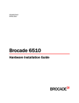
LED locations
FIGURE 4 Port Side LEDs on the Brocade 5100.
1. System status LED (top) and System power (bottom)
2. Ethernet port Status LEDs (green/amber)
3. FC port status (port 9)
FIGURE 5 Non-Port Side LEDs on the Brocade 5100.
1. Power supply status LED
2. Power supply status LED
LED Patterns
The following table describes the LEDs and their actions on the switch.
TABLE 2 Brocade 5100 LED Patterns During Normal Operation
28
LED Name
LED Color
Status of Hardware
Recommended Action
Power Supply
Status
No light
Primary power cord is disconnected
or is not actively powered, or power
supply has failed.
Verify the power supply is on and
seated and the power cord is
connected to a functioning power
source.
Steady green
Power supply is operating normally.
No action required.
Brocade 5100 Hardware Installation Guide
53-1000854-07
Brocade 5100 Operation
TABLE 2 Brocade 5100 LED Patterns During Normal Operation (Continued)
LED Name
LED Color
Status of Hardware
Recommended Action
Flashing green (for
more than five
seconds)
A power supply and fan assembly
fault has occurred for one of the
following reasons:
Take one of the following actions:
• The power supply or fan in the
assembly has failed.
• The FRU was disabled by a user.
• The FRU power switch has been
turned off or the unit has been
unplugged.
Power Status
No light
System is off or there is an internal
power supply failure.
•
•
Replace the FRU
Verify that the power supply/fan
assembly FRU is enabled
• Check the power switch and
plug
Verify the system is on. If the
system is on, the unit is faulty.
Contact Technical Support.
System Status
Steady green
System is on and power supplies are No action required.
functioning properly.
No light
System is off, boot is not complete,
or boot failed.
Steady green
System is on and power supplies are No action required.
functioning properly.
Steady amber (for
more than five
seconds)
Boot failed, the system is faulty.
Verify the system is on and has
completed booting.
Perform the following steps:
Connect a serial cable to the
system.
Reboot the system.
Check the failure indicated on the
system console.
Contact Technical Support.
Flashing amber/
green
Ethernet
Speed
Ethernet Link
Port Status
Brocade 5100 Hardware Installation Guide
53-1000854-07
Attention is required. A number of
variables can cause this status
including a single power supply
failure, a fan failure, or one or more
environmental ranges has exceeded.
Check the management interface
and the error log for details on the
cause of status.
No light
Port speed is 10 Mbps.
No action required.
Steady green
Port speed is 100 Mbps.
No action required.
No light
There is no link.
Verify the Ethernet cable is
connected correctly.
Steady amber
There is a link.
No action required.
Flickering amber
There is link activity (traffic).
No action required.
No light
No signal or light carrier (media or
cable) detected.
Check transceiver and cable.
Contact Technical Support if
required.
29
POST and boot specifications
TABLE 2 Brocade 5100 LED Patterns During Normal Operation (Continued)
LED Name
LED Color
Status of Hardware
Recommended Action
Slow flashing green Port is online but segmented
(flashing in twobecause of a loopback cable or
second intervals)
incompatible switch connection.
No action required.
Fast flashing green
(flashing in halfsecond intervals)
Port is online and an internal
loopback diagnostic test is running.
No action required.
Flickering green
(steady with
random flashes)
Port is online and frames are flowing
through the port.
No action required.
Steady green
Port is online (connected to external
device) but has no traffic.
No action required.
Slow flashing
amber (flashing in
two-second
intervals)
Port is disabled (because of
diagnostics or the portDisable
command).
Verify the diagnostic tests are not
running. Reenable the port using
the portEnable command.
Fast flashing amber Port is faulty.
(flashing in halfsecond intervals)
Check the management interface
and the error log for details on the
cause of status.
Contact Technical Support if
required.
Steady amber (for
more than five
seconds)
Port is receiving light or signal carrier No action required.
at 4 Gbps; but is not yet online.
POST and boot specifications
When the switch is turned on or rebooted, the switch performs POST. Total boot time with POST can
be several minutes. POST can be omitted after subsequent reboots by using the fastboot command
or entering the diagDisablePost command to persistently disable POST.
For more information about these commands, refer to the Fabric OS Command Reference Manual .
POST
The success or failure results of the diagnostic tests that run during POST can be monitored through
the error log or the command line interface.
POST includes the following tasks:
1. Conducts preliminary POST diagnostics.
2. Initializes the operating system.
3. Initializes hardware.
4. Runs diagnostic tests on several functions, including circuitry, port functionality, memory, statistics
counters, and serialization.
30
Brocade 5100 Hardware Installation Guide
53-1000854-07
Boot
Boot
In addition to POST, boot includes the following tasks after POST is complete:
1. Performs universal port configuration.
2. Initializes links.
3. Analyzes fabric. If any ports are connected to other switches, the switch participates in a fabric
configuration.
4. Obtains a domain ID and assigning port addresses.
5. Constructs unicast routing tables.
6. Enables normal port operation.
Interpreting POST results
POST is a system check that is performed each time the switch is powered on, rebooted, or reset.
During POST, the LEDs flash either amber or green. Any errors that occur during POST are listed in the
error log.
Complete the following steps to determine whether POST completed successfully and whether any
errors were detected:
1. Verify that the switch LEDs indicate that all components are healthy.
See the LED patterns section for descriptions and interpretations of LED patterns. If one or more
LEDs do not display a healthy state, verify that the LEDs on the switch are not set to "beacon" by
entering the switchShow command to detect if beaconing is active.
2. Verify that the switch prompt displays on the terminal of a computer workstation connected to the
switch.
If there is no switch prompt when POST completes, press Enter. If the switch prompt still does not
display, try opening a Telnet session or accessing the switch through another management tool. If
this is not successful, the switch did not successfully complete POST. Contact your switch supplier
for repair.
3. Review the switch system log for errors. Any errors detected during POST are written to the system
log, accessible through the errShow command.
For information about all referenced commands, and on accessing the error log, refer to Fabric OS
Administrator’s Guide . For information about error messages, refer to the Fabric OS Message
Reference Manual .
Maintaining the Brocade 5100
The Brocade 5100 does not require any regular physical maintenance and is designed for high
availability and to minimize the chance of failure. It includes diagnostic tests and field-replaceable units,
described in the following sections.
Brocade 5100 Hardware Installation Guide
53-1000854-07
31
Installing an SFP
Installing an SFP
The Brocade 5100 only supports Brocade-branded SFPs. If you use an unqualified SFP, the
switchShow command output shows the port in a Mod_Inv state. Fabric OS also logs the issue in the
system error log.
Complete the following steps to install an SFP.
1. Making sure that the bail (wire handle) is in the unlocked position, place the SFP in the correctly
oriented position on the port, as shown in the following figure.
2. Slide the SFP into the port until you feel it click into place; then close the bail.
NOTE
Each SFP has a 10-pad gold-plated PCB-edge connector on the bottom. The correct position to
insert an SFP into the upper row of ports is with the gold edge down. The correct position to insert
an SFP into the lower row of ports is with the gold edge up.
FIGURE 6 Installing an SFP in the upper row of port slot
Diagnostic tests
In addition to POST, the Fabric OS includes diagnostic tests to help you troubleshoot the hardware
and firmware. This includes tests of internal connections and circuitry, fixed media, and the
transceivers and cables in use.
The tests are implemented by command, either through a Telnet session or through a terminal set up
for a serial connection to the switch. Some tests require the ports to be connected by external cables,
to allow diagnostics to verify the serializer/deserializer interface, transceiver, and cable. Some tests
require loopback plugs.
Diagnostic tests are run at link speeds of 1, 2, 4, and 8 Gbps depending on the speed of the link being
tested.
NOTE
Diagnostic tests might temporarily lock the transmit and receive speed of the links during diagnostic
testing.
For information about specific diagnostic tests, refer to the Fabric OS Troubleshooting and Diagnostics
Guide.
32
Brocade 5100 Hardware Installation Guide
53-1000854-07
Field Replaceable Units (FRUs)
Field Replaceable Units (FRUs)
The power supplies have the fans inside and can be replaced onsite without the use of special tools.
The power supply/fan assembly units are keyed to ensure correct orientation during installation.
Replacement instructions are provided with all replacement units ordered.
Power supply/fan assembly FRU replacement
The Brocade 5100 fans are fixed inside the integrated power supply/fan FRU to provide necessary
airflow to cool the whole system. There is one fan located in the rear section of each FRU. The system
software sets fan speed and measures their speeds through the tachometer interface.
The two power supply/fan assembly FRU units are hot-swappable if replaced one at a time. They are
identical and fit into either slot.
Fabric OS identifies the power supplies as follows (viewing the switch from the port side):
• Power supply #1 is on the left
• Power supply #2 is on the right
Determining power supply/fan replacement need
1. Use one of the following methods to determine whether a power supply requires replacement:
• Check the power supply status LED next to the I/O switch. If the power supply status LED is not
on, verify that the power supply is on and seated and the power cord is connected to a functioning
power source. If the light does not turn green, the power supply needs to be replaced.
• In Web Tools, click the Power Status icon.
• Type the psShow command at the command prompt to display power supply status as shown
below:
switch:admin> psshow
Power Supply #1 is OK
Power Supply #2 is OK
2. Use one of the following methods to determine whether a fan requires replacement:
• Check the system status LED (see LED locations section for location of system status LED). If the
system status LED is flashing amber and green, it could mean the fan has failed. The green power
supply/fan LED will also flash in the event of failure. Check the management interface and the
error log for details on the cause of status.
• In Advanced Web Tools, check the Fan Status icon background color. It will be either yellow or
red if the fan has failed. When the fan is functioning correctly, the background color is green.
• Type the fanShow command at the command prompt to display fan status as shown below:
switch:admin> fanshow
Fan 1 is OK, speed is 7105 RPM
Fan 2 is OK, speed is 7258 RPM
For further information on replacing the power/fan units, see the Brocade 5100 Power Supply and
Fan Assembly Replacement Procedure .
Brocade 5100 Hardware Installation Guide
53-1000854-07
33
Managing the Brocade 5100
Managing the Brocade 5100
You can use the management functions built into the Brocade 5100 to monitor the fabric topology, port
status, physical status, and other information to help you analyze switch performance and to
accelerate system debugging.
The Brocade 5100 automatically performs power-on-self-test (POST) each time it is turned on. Any
errors are recorded in the error log. For more information about POST, see POST and boot
specifications on page 30.
For information about upgrading the version of Fabric OS installed on your switch, refer to the Fabric
OS Administrator’s Guide.
You can manage the Brocade 5100 using any of the management options listed in the following table.
TABLE 3 Management Options for the Brocade 5100 Switch
Management Tool
Out-of-band Support
In-band Support
Command line interface (CLI)
Ethernet or serial
connection
IP over Fibre Channel
Ethernet or serial
connection
IP over Fibre Channel
Ethernet or serial
connection
IP over Fibre Channel
Ethernet or serial
connection
IP over Fibre Channel
Ethernet or serial
connection
Native in-band interface(over
HBA only)
Ethernet or serial
connection
IP over Fibre Channel
Up to two admin sessions and four user sessions
simultaneously. For more information, refer to the
Fabric OS Administrator’s Guide and the Fabric OS
Command Reference Manual .
Brocade Web Tools
For information, refer to the Web Tools Administrator’s
Guide .
Standard SNMP applications
For information, refer to the MIB Reference Manual .
Brocade Fabric Manager (option to purchase)
For information, refer to the Fabric Manager
Administrator’s Guide .
Management Server
For information, refer to the Fabric OS Administrator’s
Guide and the Fabric OS Command Reference
Manual .
EFCM (option to purchase)
For information, refer to the EFCM documentation set.
NOTE
To achieve in-band support for IP over Fibre Channel, the software must be run on both the HBA and
the switch, and it must be supported by both the HBA and HBA driver.
34
Brocade 5100 Hardware Installation Guide
53-1000854-07
Removal and Replacement of Combined Power Supply and Fan
Assembly (Port-side Air Exhaust)
● Before beginning installation........................................................................................... 35
● Installing a combined power supply and fan assembly FRU...........................................35
Before beginning installation
This section describes how to change a power supply/fan assembly for a unit with a port-side air
exhaust. A new power supply/fan assembly field replaceable unit (FRU) must have the same part
number (P/N) as the FRU being replaced. The manufacturing P/N is located on the top of the power
supply/fan assembly.
The fans inside a power supply/fan assembly FRU either intake air or exhaust air from the chassis,
depending on the model. If your FRU requires port-side air intake, refer to the Combined Power Supply
and Fan Assembly Replacement Procedure for Port-side Air Intake. In addition to the part number, portside intake assemblies are also identified by a green label with an E on it.
Using the same P/N for all power supply/fan assembly FRUs ensures identical airflow for all the FRUs
on the chassis. The power supply/fan assembly unit handle color is also an indicator of the model type.
The handles for the installed FRUs must be the same color.
FIGURE 7 Power supply and fan assembly with part number
Installing a combined power supply and fan assembly FRU
The following figure shows the two combined power supply and fan assemblies. Fabric OS identifies the
FRUs from left to right as fan assembly #2 and fan assembly #1.
FIGURE 8 Power supply and fan assemblies on the non-port side
Disassembling any part of the power supply and fan assembly voids the warranty and regulatory
certifications. There are no user-serviceable parts inside the power supply and fan assembly.
Brocade 5100 Hardware Installation Guide
53-1000854-07
35
Time required
CAUTION
Changes or modifications made to this device that are not expressly approved by the party
responsible for compliance could void the user's authority to operate the equipment.
Because the cooling system relies on pressurized air, do not leave any of the fan assembly slots
empty longer than two minutes while the switch is operating. If a fan assembly fails, leave it in the
switch until it can be replaced. Maintain all fan assemblies in operational condition to provide
redundancy.
CAUTION
If you do not install a module or a power supply in a slot, you must keep the slot filler panel in
place. If you run the chassis with an uncovered slot, the system will overheat.
The following table describes the power supply/fan assembly status LED colors, behaviors, and
actions required, if any.
TABLE 4 LED behavior, description, and required actions
LED color and behavior
Description
Action required
No light
Power supply and fan assembly is
not receiving power.
Verify that the power supply and fan
assembly FRU is seated correctly.
Steady green
Power supply and fan assembly is
operating normally.
No action required.
Flashing green (for more than five
seconds)
A power supply and fan assembly
fault has occurred for one of the
following reasons:
Take one of the following actions:
•
•
• The power supply or fan in the
assembly has failed.
•
• The FRU was disabled by a user.
• The FRU power switch has been
turned off or the unit has been
unplugged.
Replace the FRU.
Verify that the power supply/fan
assembly FRU is enabled.
Check the power switch and
plug.
Time required
Replacing a fan assembly in the switch should take less than two minutes.
Items required
You need the following items to replace a power supply and fan assembly.
• New power supply and fan assembly FRU.
• Phillips-head screwdriver #1.
Replacing the power supply/fan assembly
Complete the following steps to replace a power supply and fan assembly.
36
Brocade 5100 Hardware Installation Guide
53-1000854-07
Removal and Replacement of Combined Power Supply and Fan Assembly (Port-side Air Exhaust)
1. Unscrew the captive screw on the power supply/fan assembly you are replacing using a Phillips-head
screwdriver.
2. Remove the power supply/fan assembly from the chassis by pulling the handle out, away from the
chassis.
3. Confirm that the new power supply/fan assembly has the same part number as the removed one.
4. Install the new power supply/fan assembly in the chassis:
a)
Orient the new fan assembly as shown in the following figure, with the captive screw on the
right.
FIGURE 9 Orientation of the power supply and fan assembly FRU
b)
Gently push the power supply/fan assembly into the chassis until it is firmly seated.
NOTE
Do not force the installation. If the FRU does not slide in easily, ensure that it is correctly
oriented before continuing.
CAUTION
Carefully follow the mechanical guides on each side of the power supply slot and
make sure the power supply is properly inserted in the guides. Never insert the power
supply upside down.
c)
Secure the power supply/fan assembly to the chassis by screwing in the captive screw
using the Phillips-head screwdriver.
5. Verify that the fan status LED is lit steady green to indicate normal operation.
6. Optionally, display the fan status using the fanShow command from the CLI.
Brocade 5100 Hardware Installation Guide
53-1000854-07
37
Replacing the power supply/fan assembly
38
Brocade 5100 Hardware Installation Guide
53-1000854-07
Brocade 5100 Technical Specifications
This document highlights the features and specifications for the Brocade 5100 switches.
System specifications
System component
Description
Enclosure
Non-port to port side airflow; 1U form factor, power from non-port side
Power inlet
C13
Power supplies
Dual, hot-swappable redundant power supplies with integrated system cooling fans
Fans
Two fans
Cooling
Integrated system cooling fans
System architecture
Nonblocking shared-memory switch
System processors
Power PC 440EPX and 667 MHz CPU
Fibre Channel
System component
Description
Fibre Channel ports
Switch mode (default): 24-, 32-, and 40-port configurations (8-port increments through
Ports on Demand licenses); universal (E, F, M, EX, FL) ports
Access Gateway default port mapping: 32 F_Ports, 8 N_Ports
ANSI Fibre Channel
protocol
FC-PH (Fibre Channel Physical and Signaling Interface standard)
Modes of operation
Fibre Channel Class 2 and Class 3
Fabric initialization
Complies with FC-SW-3 Rev. 6.6
FCIP (IP over Fibre
Channel)
Complies with FC-IP 2.3 of FCA profile
Port Status
40 port status LEDs
Brocade 5100 Hardware Installation Guide
53-1000854-07
39
Brocade 5100 Technical Specifications
LEDs
System component
Description
Switch status and
management
One system status LED (above) on the left side
One power status LED (below) on the left side
40 port status LEDs, one for each Fibre Channel port, located above the ports
One power supply status LED on each power supply FRU, to the left of the ON/OFF
rocker switch on the non-port side of the switch
Other
System component
Description
Serial Cable
RJ-45 connector cable
RJ-45 to DB9 adaptor
RJ-45 to DB9 for console cable
RJ-45 connector
10/100 Ethernet management port; in-band over Fibre Channel; serial port (RJ-45)
Weight and physical dimensions
Model
Height
Width
Depth
Weight
Brocade 5100
4.3 cm
42.9 cm
61 cm
9.3 kg
1.7 inches
16.9 inches
24 inches
20.6 inches
Environmental requirements
Condition
40
Operational
Non-operational
Ambient temperature 0°C to 40°C (32°F to 104°F)
-25°C to 70°C (-13°F to 158°F)
Relative humidity
(non-condensing)
10% to 85% at 40°C (104°F)
10% to 95 % at 70°C (158°F)
Altitude (above sea
level)
0 to 3000 m (10,000 feet)
0 to 12000 m (40,000 feet)
Shock
20 G, 6 ms, half-sine wave
33 G, 11 ms, half-sine wave, 3/eg Axis
Vibration
0.5 G sine, 0.4 gms random, 5-500 Hz
2.0 G sine, 1.1 gms random, 5-500 Hz
Brocade 5100 Hardware Installation Guide
53-1000854-07
Brocade 5100 Technical Specifications
Condition
Operational
Non-operational
Airflow
Maximum: 49.3 cmh (29 cfm)
N/A
Nominal: 37.4 cmh (22 cfm)
Heat dissipation
311 BTU/hr (Maximum 40 ports)
N/A
Power supply specifications (per PSU)
Power supply Maximum
model
output power
rating (DC)
Input voltage
Input line
frequency
Maximum
input current
Input line
protection
Maximum
inrush
current
Not available
100 - 240 V
(nominal)
50/60 Hz
(nominal)
16 A
Both AC lines
fused
35 A
85 - 264 V
(range)
47 - 63 Hz
(range)
150 W
Power consumption
110 W with all 48 ports populated with 16 Gbps SWL optics.
72 W with empty chassis and no optics.
Data port specifications (Fibre Channel)
Name
Number
Description
Brocade 5100
1, 2 , 4 and 8
Gbps
Configurations of 24, 32, or 40 ports in an efficiently designed 1U package
Fibre Channel data transmission ranges
Port speed (Gbps)
Cable size
(microns)
Short wavelength
(SWL)
Long wavelength
(LWL)
Extended long
wavelength (ELWL)
1
50
500 m (1,640 feet)
(OM2); 860 m (2,821
feet) (OM3)
N/A
N/A
62.5
300 m (984 feet)
N/A
N/A
9
N/A
10 km (6.2 miles)
80 km (50 miles)
Brocade 5100 Hardware Installation Guide
53-1000854-07
41
Brocade 5100 Technical Specifications
Port speed (Gbps)
Cable size
(microns)
Short wavelength
(SWL)
Long wavelength
(LWL)
Extended long
wavelength (ELWL)
2
50
300 m (984 feet)
(OM2); 500 m (1,640
feet) (OM3)
N/A
N/A
62.5
150 m (492 feet)
10 km (6.2 miles)
80 km (50 miles)
9
N/A
10 km (6.2 miles)
80 km (50 miles)
50
150 m (492 feet)
(OM2); 380 m (1,246
feet) (OM3)
N/A
N/A
62.5
70 m (230 feet)
N/A
N/A
9
N/A
N/A
N/A
50
50 m (164 feet)
(OM2); 150 m (492
feet) (OM3)
N/A
N/A
62.5
21 m (69 feet)
N/A
N/A
9
N/A
10 km
N/A
4
8
Serial port specifications (pinout RJ-45)
42
Pin
Signal
Description
1
Not supported
N/A
2
Not supported
N/A
3
UART1_TXD
Transmit data
4
GND
Logic ground
5
GND
Logic ground
6
UART1_RXD
Receive data
7
Not supported
N/A
8
Not supported
N/A
Brocade 5100 Hardware Installation Guide
53-1000854-07
Brocade 5100 Technical Specifications
Serial port specifications (protocol)
Parameter
Value
Baud
9600
Data bits
8
Parity
None
Stop bits
1
Flow control
None
Memory specifications
Memory
Type
Size
Main memory
SDRAM
512 MB
Boot Flash
4 MB
Compact Flash
1 GB
Regulatory compliance (EMC)
•
•
•
•
•
•
•
•
•
ANSI C63.4
ICES-003 Class A
CISPR22 and JEIDA
EN55022 and EN55024
EN55022 or CISPR22 or AS/NZS CISPR22
51318.22-99 and 51318.24.99
KN22 and KN24
GB17625.1-2003
CNS 13438(95)
Regulatory compliance (immunity)
• EN50082-2/EN55024:1998 (European Immunity Requirements)
Brocade 5100 Hardware Installation Guide
53-1000854-07
43
Brocade 5100 Technical Specifications
‐
‐
EN61000-3-2/JEIDA (European and Japanese Spec)
EN61000-3-3
Regulatory compliance (safety)
•
•
•
•
•
Bi-Nat UL/CSA 60950-1
EN 60950-1
IEC 60950-1
GB4943-2001 and GB9254-1998
CNS 14336(94)
Regulatory compliance (environmental)
• 2011/65/EU - Restriction of the use of certain hazardous substance in electrical and electronic
equipment (EU RoHS).
• 2012/19/EU - Waste electrical and electronic equipment (EU WEEE).
• 94/62/EC - packaging and packaging waste (EU).
• 2006/66/EC - batteries and accumulators and waste batteries and accumulators (EU battery
directive).
• 1907/2006 of the European Parliament and of the Council of 18 December 2006 concerning the
Registration, Evaluation, Authorisation and Restriction of Chemicals (EU REACH).
• Section 1502 of the Dodd-Frank Wall Street Reform and Consumer Protection Act of 2010 - U.S.
Conflict Minerals.
• 30/2011/TT-BCT - Vietnam circular.
• SJ/T 11363-2006 Requirements for Concentration Limits for Certain Hazardous Substances in EIPs
(China).
• SJ/T 11364-2006 Marking for the Control of Pollution Caused by EIPs (China).
44
Brocade 5100 Hardware Installation Guide
53-1000854-07
Regulatory Statements
● BSMI statement (Taiwan)................................................................................................45
● Canadian requirements...................................................................................................45
● CE Statement..................................................................................................................45
● China CC statement........................................................................................................46
● China ROHS................................................................................................................... 46
● FCC warning (US only)................................................................................................... 47
● KCC statement (Republic of Korea)................................................................................47
● VCCI statement...............................................................................................................47
BSMI statement (Taiwan)
Warning:
This is Class A product. In a domestic environment this product may cause radio interference in which
case the user may be required to take adequate measures.
Canadian requirements
This Class A digital apparatus meets all requirements of the Canadian Interference-Causing Equipment
Regulations, ICES-003 Class A.
Cet appareil numérique de la classe A est conforme à la norme NMB-003 du Canada.
CE Statement
ATTENTION
This is a Class A product. In a domestic environment, this product might cause radio interference, and
the user might be required to take corrective measures.
The standards compliance label on this device contains the CE mark which indicates that this system
conforms to the provisions of the following European Council directives, laws, and standards:
• Electromagnetic Compatibility (EMC) Directive 2004/108/EEC
• Low Voltage Directive (LVD) 2006/95/EC
• EN50082-2/EN55024:1998 (European Immunity Requirements)
Brocade 5100 Hardware Installation Guide
53-1000854-07
45
China CC statement
‐
‐
EN61000-3-2/JEIDA (European and Japanese Harmonics Spec)
EN61000-3-3
China CC statement
China ROHS
Refer to the latest revision of the China ROHS document (P/N 53‐1000428‐xx) which ships with the
product.
46
Brocade 5100 Hardware Installation Guide
53-1000854-07
FCC warning (US only)
FCC warning (US only)
This equipment has been tested and complies with the limits for a Class A computing device pursuant
to Part 15 of the FCC Rules. These limits are designed to provide reasonable protection against harmful
interference when the equipment is operated in a commercial environment.
This equipment generates, uses, and can radiate radio frequency energy, and if not installed and used
in accordance with the instruction manual, might cause harmful interference to radio communications.
Operation of this equipment in a residential area is likely to cause harmful interference, in which case
the user will be required to correct the interference at the user’s own expense.
KCC statement (Republic of Korea)
Class A device (Broadcasting Communication Device for Office Use): This device obtained EMC
registration for office use (Class A), and may be used in places other than home. Sellers and/or users
need to take note of this.
VCCI statement
This is a Class A product based on the standard of the Voluntary Control Council for Interference by
Information Technology Equipment (VCCI). If this equipment is used in a domestic environment, radio
disturbance might arise. When such trouble occurs, the user might be required to take corrective
actions.
Brocade 5100 Hardware Installation Guide
53-1000854-07
47
VCCI statement
48
Brocade 5100 Hardware Installation Guide
53-1000854-07
Cautions and Danger Notices
● Cautions.......................................................................................................................... 49
● Danger Notices............................................................................................................... 52
Cautions
A Caution statement alerts you to situations that can be potentially hazardous to you or cause damage
to hardware, firmware, software, or data.
Ein Vorsichthinweis warnt Sie vor potenziellen Personengefahren oder Beschädigung der Hardware,
Firmware, Software oder auch vor einem möglichen Datenverlust
Un message de mise en garde vous alerte sur des situations pouvant présenter un risque potentiel de
dommages corporels ou de dommages matériels, logiciels ou de perte de données.
Un mensaje de precaución le alerta de situaciones que pueden resultar peligrosas para usted o causar
daños en el hardware, el firmware, el software o los datos.
General cautions
CAUTION
Changes or modifications made to this device that are not expressly approved by the party
responsible for compliance could void the user's authority to operate the equipment.
VORSICHT
Falls dieses Gerät verändert oder modifiziert wird, ohne die ausdrückliche Genehmigung der für
die Einhaltung der Anforderungen verantwortlichen Partei einzuholen, kann dem Benutzer der
weitere Betrieb des Gerätes untersagt werden.
MISE EN
GARDE
Les éventuelles modifications apportées à cet équipement sans avoir été expressément
approuvées par la partie responsable d'en évaluer la conformité sont susceptibles d'annuler le
droit de l'utilisateur à utiliser cet équipement.
PRECAUCIÓN
Si se realizan cambios o modificaciones en este dispositivo sin la autorización expresa de la
parte responsable del cumplimiento de las normas, la licencia del usuario para operar este
equipo puede quedar anulada.
CAUTION
Do not install the device in an environment where the operating ambient temperature might
exceed 40°C (104°F).
Brocade 5100 Hardware Installation Guide
53-1000854-07
49
Cautions and Danger Notices
VORSICHT
Das Gerät darf nicht in einer Umgebung mit einer Umgebungsbetriebstemperatur von über
40°C (104°F) installiert werden.
MISE EN
GARDE
N'installez pas le dispositif dans un environnement où la température d'exploitation ambiante
risque de dépasser 40°C (104°F).
PRECAUCIÓN
No instale el instrumento en un entorno en el que la temperatura ambiente de operación
pueda exceder los 40°C (104°F).
CAUTION
Make sure the airflow around the front, sides, and back of the device is not restricted.
VORSICHT
Stellen Sie sicher, dass an der Vorderseite, den Seiten und an der Rückseite der Luftstrom
nicht behindert wird.
MISE EN
GARDE
Vérifiez que rien ne restreint la circulation d'air devant, derrière et sur les côtés du dispositif et
qu'elle peut se faire librement.
PRECAUCIÓN
Asegúrese de que el flujo de aire en las inmediaciones de las partes anterior, laterales y
posterior del instrumento no esté restringido.
CAUTION
Ensure that the airflow direction of the power supply unit matches that of the installed fan tray.
The power supplies and fan trays are clearly labeled with either a green arrow with an "E", or
an orange arrow with an "I."
VORSICHT
Vergewissern Sie sich, dass die Luftstromrichtung des Netzteils der eingebauten Lüftereinheit
entspricht. Die Netzteile und Lüftereinheiten sind eindeutig mit einem grünen Pfeil und dem
Buchstaben "E" oder einem orangefarbenen Pfeil mit dem Buchstaben "I" gekennzeichnet.
MISE EN
GARDE
Veillez à ce que le sens de circulation de l'air du bloc d'alimentation corresponde à celui du
tiroir de ventilation installé. Les blocs d'alimentation et les tiroirs de ventilation sont étiquetés
d'une flèche verte avec un "E " ou d'une flèche orange avec un " I ".
PRECAUCIÓN
Asegúrese de que la dirección del flujo de aire de la unidad de alimentación se corresponda
con la de la bandeja del ventilador instalada. Los dispositivos de alimentación y las bandejas
del ventilador están etiquetadas claramente con una flecha verde y una "E" o con una flecha
naranja y una "I".
Electrical cautions
CAUTION
Before plugging a cable into to any port, be sure to discharge the voltage stored on the cable
by touching the electrical contacts to ground surface.
50
Brocade 5100 Hardware Installation Guide
53-1000854-07
Cautions and Danger Notices
VORSICHT
Bevor Sie ein Kabel in einen Anschluss einstecken, entladen Sie jegliche im Kabel vorhandene
elektrische Spannung, indem Sie mit den elektrischen Kontakten eine geerdete Oberfläche
berühren.
MISE EN
GARDE
Avant de brancher un câble à un port, assurez-vous de décharger la tension du câble en reliant
les contacts électriques à la terre.
PRECAUCIÓN
Antes de conectar un cable en cualquier puerto, asegúrese de descargar la tensión acumulada
en el cable tocando la superficie de conexión a tierra con los contactos eléctricos.
CAUTION
Static electricity can damage the chassis and other electronic devices. To avoid damage, keep
static-sensitive devices in their static-protective packages until you are ready to install them.
VORSICHT
Statische Elektrizität kann das System und andere elektronische Geräte beschädigen. Um
Schäden zu vermeiden, entnehmen Sie elektrostatisch empfindliche Geräte erst aus deren
antistatischer Schutzhülle, wenn Sie bereit für den Einbau sind.
MISE EN
GARDE
L'électricité statique peut endommager le châssis et les autres appareils électroniques. Pour
éviter tout dommage, conservez les appareils sensibles à l'électricité statique dans leur
emballage protecteur tant qu'ils n'ont pas été installés.
PRECAUCIÓN
La electricidad estática puede dañar el chasis y otros dispositivos electrónicos. A fin de impedir
que se produzcan daños, conserve los dispositivos susceptibles de dañarse con la electricidad
estática dentro de los paquetes protectores hasta que esté listo para instalarlos.
CAUTION
If you do not install a module or a power supply in a slot, you must keep the slot filler panel in
place. If you run the chassis with an uncovered slot, the system will overheat.
VORSICHT
Falls kein Modul oder Netzteil im Steckplatz installiert wird, muss die Steckplatztafel angebracht
werden. Wenn ein Steckplatz nicht abgedeckt wird, läuft das System heiß.
MISE EN
GARDE
Si vous n’installez pas de module ou de bloc d'alimentation dans un slot, vous devez laisser le
panneau du slot en place. Si vous faites fonctionner le châssis avec un slot découvert, le
système surchauffera.
PRECAUCIÓN
Si no instala un módulo o un fuente de alimentación en la ranura, deberá mantener el panel de
ranuras en su lugar. Si pone en funcionamiento el chasis con una ranura descubierta, el
sistema sufrirá sobrecalentamiento.
CAUTION
Carefully follow the mechanical guides on each side of the power supply slot and make sure the
power supply is properly inserted in the guides. Never insert the power supply upside down.
Brocade 5100 Hardware Installation Guide
53-1000854-07
51
Danger Notices
VORSICHT
Beachten Sie mechanischen Führungen an jeder Seite des Netzteils, das ordnungegemäß in
die Führungen gesteckt werden muss. Das Netzteil darf niemals umgedreht eingesteckt
werden.
MISE EN
GARDE
Suivez attentivement les repères mécaniques de chaque côté du slot du bloc d'alimentation et
assurez-vous que le bloc d'alimentation est bien inséré dans les repères. N'insérez jamais le
bloc d'alimentation à l'envers.
PRECAUCIÓN
Siga cuidadosamente las guías mecánicas de cada lado de la ranura del suministro de
energía y verifique que el suministro de energía está insertado correctamente en las guías.
No inserte nunca el suministro de energía de manera invertida.
Danger Notices
A Danger statement indicates conditions or situations that can be potentially lethal or extremely
hazardous to you. Safety labels are also attached directly to products to warn of these conditions or
situations.
Ein Gefahrenhinweis warnt vor Bedingungen oder Situationen die tödlich sein können oder Sie extrem
gefährden können. Sicherheitsetiketten sind direkt auf den jeweiligen Produkten angebracht um vor
diesen Bedingungen und Situationen zu warnen.
Un paragraphe Danger indique des conditions ou des situations potentiellement mortelles ou
extrêmement dangereuses. Des labels de sécurité sont posés directement sur le produit et vous
avertissent de ces conditions ou situations
Una advertencia de peligro indica condiciones o situaciones que pueden resultar potencialmente
letales o extremadamente peligrosas. También habrá etiquetas de seguridad pegadas directamente
sobre los productos para advertir de estas condiciones o situaciones.
General dangers
DANGER
The procedures in this manual are for qualified service personnel.
GEFAHR
Die Vorgehensweisen in diesem Handbuch sind für qualifiziertes Servicepersonal bestimmt.
DANGER
Les procédures décrites dans ce manuel doivent être effectuées par un personnel de
maintenance qualifié.
PELIGRO
Los procedimientos de este manual deben llevarlos a cabo técnicos cualificados.
Electrical dangers
DANGER
For safety reasons, the ESD wrist strap should contain a series 1 megaohm resistor.
52
Brocade 5100 Hardware Installation Guide
53-1000854-07
Cautions and Danger Notices
GEFAHR
Aus Sicherheitsgründen sollte ein EGB-Armband zum Schutz von elektronischen gefährdeten
Bauelementen mit einem 1 Megaohm-Reihenwiderstand ausgestattet sein.
DANGER
Pour des raisons de sécurité, la dragonne ESD doit contenir une résistance de série 1 méga
ohm.
PELIGRO
Por razones de seguridad, la correa de muñeca ESD deberá contener un resistor en serie de 1
mega ohmio.
DANGER
Make sure that the power source circuits are properly grounded, then use the power cord
supplied with the device to connect it to the power source.
GEFAHR
Stellen Sie sicher, dass die Stromkreise ordnungsgemäß geerdet sind. Benutzen Sie dann das
mit dem Gerät gelieferte Stromkabel, um es an die Srromquelle anzuschließen.
DANGER
Vérifiez que les circuits de sources d'alimentation sont bien mis à la terre, puis utilisez lecordon
d'alimentation fourni avec le dispositif pour le connecter à la source d'alimentation.
PELIGRO
Verifique que circuitos de la fuente de corriente están conectados a tierra correctamente; luego
use el cordón de potencia suministrado con el instrumento para conectarlo a la fuente de
corriente
DANGER
Remove both power cords before servicing.
GEFAHR
Trennen Sie beide Netzkabel, bevor Sie Wartungsarbeiten durchführen.
DANGER
Retirez les deux cordons d'alimentation avant toute maintenance.
PELIGRO
Desconecte ambos cables de alimentación antes de realizar reparaciones.
DANGER
Disconnect the power cord from all power sources to completely remove power from the device.
GEFAHR
Ziehen Sie das Stromkabel aus allen Stromquellen, um sicherzustellen, dass dem Gerät kein
Strom zugeführt wird.
DANGER
Débranchez le cordon d'alimentation de toutes les sources d'alimentation pour couper
complètement l'alimentation du dispositif.
PELIGRO
Para desconectar completamente la corriente del instrumento, desconecte el cordón de
corriente de todas las fuentes de corriente.
Brocade 5100 Hardware Installation Guide
53-1000854-07
53
Cautions and Danger Notices
DANGER
To avoid high voltage shock, do not open the device while the power is on.
GEFAHR
Das eingeschaltete Gerät darf nicht geöffnet werden, da andernfalls das Risiko eines
Stromschlags mit Hochspannung besteht.
DANGER
Afin d'éviter tout choc électrique, n'ouvrez pas l'appareil lorsqu'il est sous tension.
PELIGRO
Para evitar una descarga de alto voltaje, no abra el dispositivo mientras esté encendido.
DANGER
Risk of explosion if battery is replaced by an incorrect type. Dispose of used batteries
according to the instructions.
GEFAHR
Es besteht Explosionsgefahr, wenn ein unzulässiger Batterietyp eingesetzt wird.
Verbrauchte Batterien sind entsprechend den geltenden Vorschriften zu entsorgen.
DANGER
Risque d'explosion en cas de remplacement de la pile par un modèle incorrect.
Débarrassez-vous des piles usagées conformément aux instructions.
PELIGRO
Riesgo de explosión si se sustituye la batería por una de tipo incorrecto.
Deshágase de las baterías usadas de acuerdo con las instrucciones.
Dangers related to equipment weight
DANGER
Make sure the rack housing the device is adequately secured to prevent it from becoming
unstable or falling over.
54
GEFAHR
Stellen Sie sicher, dass das Gestell für die Unterbringung des Geräts auf angemessene Weise
gesichert ist, so dass das Gestell oder der Schrank nicht wackeln oder umfallen kann.
DANGER
Vérifiez que le bâti abritant le dispositif est bien fixé afin qu'il ne devienne pas instable ou qu'il
ne risque pas de tomber.
PELIGRO
Verifique que el bastidor que alberga el instrumento está asegurado correctamente para evitar
que pueda hacerse inestable o que caiga.
Brocade 5100 Hardware Installation Guide
53-1000854-07
Index
A
I
access
installing a Brocade 5100 into an EIA cabinet 21
installing an SFP 32
installing a stand-alone Brocade 5100 21
interpreting POST results 31
ISL trunking groups 15
items required for installation 20
NTP 26
accessory kit 20
B
Brocade Advanced Web Tools 34
Brocade Fabric Manager 34
Brocade ISL Trunking 13, 15
BSMI statement (Taiwan) 45
C
Canadian requirements 45
CE statement 45
Command line interface (CLI) 34
configuring
date and time 24
NTP 26
configuring the Brocade 5100 22
L
LEDs
interpreting 27
on front panel 27
local clock 26
LOCL 26
logging
timestamp 24
M
Management Server 34
monitoring
through LED activity 27
D
date 25
date and time 24
diagnostic tests
N
NTP
access 26
about 32
E
P
EFCM 34
port
EIA rack
requirements 12
event
date and time 24
F
trunking 13, 15
port numbering 13
ports, enabling 15
ports, numbering 13
Ports On Demand 15
port status LEDs 27
POST
Fabric Manager 34
FCC warning (US only) 47
Field replaceable units (FRUs) 14
front panel
LEDs 27
Brocade 5100 Hardware Installation Guide
53-1000854-07
55
error messages 31
interpreting 31
POST and boot specifications 30
power status LED 27
power supply status LED 27
provide power to the switch 22
R
rack
requirements 12
recommendations for cable management 20
requirements
airflow 12
electrical 12
environmental 12
facility 12
rack 12
RTC battery 18
S
setting
time zone 25
settings
date and time 24
setting the date and time 24
setting the IP address 23
Setting time zones 25
SNMP 34
system status LED 27
T
tests, diagnostic 32
time 24
time and datedate and timesetting the switch date and
time 24
time zones 24
Time zones 24
trunking
about 13, 15
tsclockserver 25, 26
tsTimeZone 25
V
VCCI statement 47
56
Brocade 5100 Hardware Installation Guide
53-1000854-07