1
CE300993
Tuning-Fork Scale
HG
S&J? ± O S
( CE TYPE )
Operation Manual
-looo
Tokyo
CONTENTS
PAGE
INTRODUCTION
1
Four Basic Scale Modes
1
Four Basic Functions
1
Thirteen Weight Unit Variation
2
Other Specifications
2
Model s
2
EXTERNAL VIEW & NAMES OF PARTS
3
Key Function
3
Characters
3
INSTALLATION
4
Unpacking, Unlocking, Pan Loading
4
Leveling, Starting
5
Cautions on Use
5
SCALE MODE SETTING
6
How to Select a SCale Mode
6
1. Precision Weighing Scale Mode
7
Taring, Bar Graph Display
7
2. Counting Scale Mode
8
3. Percent SCale Mode
10
100% Setting with Reference Sample
10
100% Setting by Key Operation
11
4. Conversion SCale Mode
12
VARIOUS FUNCTIONS
13
How to Select Functions
13
Setting of Judgement Range
14
B. Accumulation Function
15
C. Comparator Function
16
Setting with Reference Sample
16
Setting by Key Operation
17
Ranking Indication of Judgment Result.
18
SELECTION OF TWO WEIGHT UNITS
18
VARIATIONS OF MEASUREMENT MODE in combination of functions...19
HOW TO VERIFY /CHNAGE MODE
19
CONTENTS OF VARIOUS FUNCTIONS
20
Part I Contents of Basic Function Modes
20
Part I - 2 Various Weight Units & Readability
Selection
21
Part II Contents of Comparator Functions
22
Part III Conditions & Results, Integration Time
& Stabilization Speed
Part IV Contents of INterface
23
23
LIST OF VARIOUS MESSAGES
Displays, Beeps
TROUBLESHOOTINGS
CALIBRATION
24
24
25
26
BATTERY OPTION
OUTPUT FORMAT
27
28
(2)
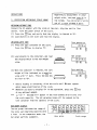
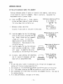
Congratulations to be one of the owners of the multi-purpose tuning-fork
scale VIBRA - HG series !
With 6 different weight unit displays, the VIBRA - HG scale offers 16 varieties
of function complex, which will satisfy you in any weighing field.
To get the optimum result, select the most suitable function to your weighing
purposes and conditions out of the full menu programmed for owners of VIBRA.
Let's start to look into the world of VIBRA !
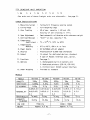
FOUR (4) BASIC SCALE MODES
page
1. High Precision Weighing Mode
1/150,000 (HG-15K) to 1/250,000 (HG-5000) divisions.
7
2. Counting + Weighing Mode
For the best controls of production and inventory,
switchable between COUNT & WEIGH by one touch.
8
3. Percentage + Weighing Mode
Automatic graduation change(1%, 0.1%, 0.01%, 0.001%) to
the loading weight. Provided for compound and mixture.
10
4. Conversion + Weighing Mode
Convertible to any optional unit by setting coefficient.
Switchable between Conversion and Weighing by one touch.
12
FOUR (4) BASIC FUNCTIONS
A. Precision Weighing Function
B. Accumulation Function
Convenient for mixing, compound or filling, sums up
every measurement data.
C. Comparator Function
Over/under judgment at upto 4 point setting, with
beep, ranking bar, or two-point bargraphs. Convenient
in checking package contents, quantity/weight.
D. Comparator + Accumulation Function
- 1-
7
15
16
16
SIX (6)WEIGHT UNIT VARIATION
1. mg
2. g
3. kg
4. ct
5. oz
6. lb
-Two units out of these 6 weight units are selectable.- See page 21.
OTHER SPECIFICATIONS
1. Measuring System
2. Taring Range
3. Zero Tracking
4. Span Adjustment
5. Overload Message
6. Temperature
Coefficient
7. Temperature/
Humidity
8. Power Source
9. Display
10. Output
11. Functions
12. Options
13. Under Weighing
Tuning-fork frequensy sensing system
Full weighing range
4% of max. capacity ( +2% and -2%)
Accuracy of zero tracking is 1/4 e.
Semi-automatic calibration with reference weight
"O-Err" at max. capacity + 9d.
-3 x 10"6/°C (10°C to 30°C)
0°C to 40°C, 80% r.h. or less
DC 9V/400mA with AC adaptor
Fluorescent of 12.5mm high characters
IJ output for dedicated devices, standard.
A type of RS232C interface pack, option.
See page 1.
1. Rechargeable built-in battery unit
2. Dedicated printers (CSP-16, CSP-193)
3. Bidirectional RS232C output interface
Provided as standard
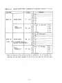
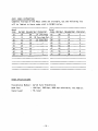
MODELS
HG-2000
HG-1000
2000g
1000g
0.005g
0.01g
0.05g
0.1g
0.005/0.01/ 0.01/0.02/
READABILITY 0.02/0.05/ 0.05/0.1/
0.2
0.1
-0.005g
io.Oig
REPEATABILITY
LINEARITY
-0.01g
io.O2g
TOLERANCE
MODELS
CAPACITY
SENSITIVITY
EC ACCURACY
PAN SIZE
WEIGHT
170mm dia
Approx. 4.5 kg
- 2 -
HG-5000
5000g
0.02g
0.2g
0.02/0.05/
0.1/0.2/
0.5
io.O2g
-0.05g
HG-10K
10kg
0.05g
0.5g
0.05/0.1/
0.2/0.5/
0.1
io.O5g
-0.1g
220mm x 180mm
Approx. 4.7 kg
HG-15K
15kg
0.1g
1 9
0.1/0.2/
0.5/1
2
-0.1g
-0.2g
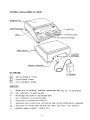
EXTERNAL VIEW & NAMES OF PARTS
Weighing Pan
T key(Tare)
F key(Function)
S key (Setting Change)
KEY FUNCTION
AC Adaptor
Setting Change & Finish
Function/Mode change
Tare & Parameter Change
CHARACTERS
g
pcs
%
#
M
Weight unit in weighing, counting, percentage mode (mg, kg, ct repiacable)
Unit indication in counting mode
Percentage indication in percentage mode
Unit indication in conversion mode
Indication in accumulation function
Indication that a particular setting has been stored.(Blinking:not complete)
Indication of settled down (Without this mark, the data is not settled.)
Automatic memory renewal ( Simple SCS )
- 3-
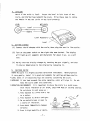
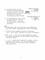
INSTALLATION
1. UNPACKING
Unpack- the container carefully. Examine the packaging and the device for
damage, and report to the shipper if any. Try to keep the scale upright.
Check for the exclosures as follows:
(T) Scale
( D Operation Manual
( D Weighing Pan with Pan Base
(?) AC Adaptor
2. UNLOCKING
Locate a black rubber cap at the top of the scale. Remove the cap to find
a lock lever in it. Turn the lever to the centre of the scale to unlock.
* Before relocation or transportaion, turn the lever to the edge of the scale
for locking mechanism.
Unlock
I
, Lock
Mechanism
Pan base fitting
screw
c
S- i-
o
o
3. WEIGHING PAN LOADING
Place the pan base packed with the weighing pan on the scale. Fix it by
driving the nut on the pan base to the screw in the centre of the scale.
Place the weighing pan properly on the pan base.
=
Weighing Pan
Pan Base
Drive this nut.
Pan Base<=0>
Scale
* The receiving element of the pan base is directly linked with the delicate
weighing mechanism. A tension or a side force may damage the unit.
- 4 -
4. LEVELING
Watch if the scale is level. Locate the level in left front of the
scale, and knurled legs beneath the scale. Drive these legs to centre
the bubble in the red circle of the level properly.
LEVEL
NOT LEVEL
Level
Red Circle
Bubble
Level Adjusters
Level
5. GETTING STARTED
(1) Connect the AC adaptor with the scale, then plug the cord in line outlet.
(2) Turn on the1 power switch on the right side near bottom. The display
will light up all segments and characters for about 4 sec. as a self
test.
(3) Verify that the display changes by touching the pan slightly, and that
it returns immediately to the original by releasing it.
5. CAUTIONS ON USE
VIBRA HG scale is a highly accurate cprecision instrument. Handle/operate
it very gently, instal it in good environments for getting optimum results.
* LEVEL Check if all adjusting legs are securely sustaining the scale.
* OVERLOAD If the load exceeds the scale capacity, o-Err will sign it. Do not
keep the scale under this condition.
* OPERATION ENVIRONMENTS It is important to place the scale in a quiet area,
with little vibration or air draft, away from heat or cooling sources.
Do not place in such areas as :
1. Area exposed to a wind from a fan
or a cooler.
2. Area exposed to direct sunlight.
3. On an unstable base or near to
a source of vibration.
4. Area where temperature changes
abruptly.
5. Area in high humidity or dusts.
- 5 -
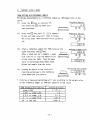
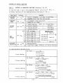
SCALE MODE SETTING
FOUR SCALE MODES
Select suitable scale mode to your purpose out of the following four modes.
1. Precision Weighing Mode : 1/250,000 to 1/150,000 divisions...see page 7.
2. Counting + Weighing Mode: High precision, easy counting
see page 8.
3. Percentage+Weighing Mode: Percentage of weight/reference
see page 10.
4. Conversion+Weighing Mode: Conversion by weight/coefficient...see page 12.
* At the time of delivery, the scale mode is set at 1. Precision Weighing Mode.
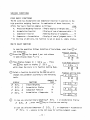
HOW TO SELECT A SCALE MODE
Calling function mode
(T) Press the I F I key for about 4 sec. and release
it when display shows Func
.
u n c
m
(T) Then display changes to / 5 f t , ., showing
the scale selection mode. Select a scale
mode by pressing the LLJ key which changes
the parameter for scale modes.
Scale mode selection
. / 5 ft. 1
LU (B
»s
Counting
DISPLAY
/ 5ft
/'
SCALE MODE
Weighing
PAGE
7
/ 5Eh
E
Counting+ Weighing
/ SEt
/ 5ft
3
H
Percentage + Weighing
Conversion + Weighing
/ 5 ft. E
8
Percentage
/ 5 ft. 3
10
12
Conversion
/ 5 ft.
Press the [_S_J key to return to measuring
mode with display of the selected mode.
Finishina mode s
(Ex.)
0 PCS
m
In this stage, pressing the \T] key instead
of the QF] key will advance to the SELECTION
OF FUNCTION. See page 13.
- 6 -
m
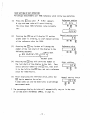
OPERATIONS
Regarding to measurement in other
weight units, see page page 18 in
1. PRECISION WEIGHING SCALE MODE
the column.
You can select 2 units
out of 6 each of Mode A and 8.
WEIGHING WITHOUT TARE
Connect the AC adaptor with the scale at the rear, plug the cord in line
outlet.
Turn the power switch of the scale.
(1) Press the jT| key and verify that the display is cleared to "0".
(2) Load objects on the scale and read the display.
WEIGHING WITH TARE
Tare operation
(1) Place the tare container on the scale.
\
0.0 0 g
Press the jT] key to display "0".
m
Net weight
(2) Load objects in the container, and read
the display which is the net weight
value.
S3 (B CD
Zero setting
n n un g„
u.u
(3) When the container is removed, the tare
weight will be indicated as a negative
value with "-" mark.
Press the {Tj key
si m
to clear to " 0 " .
*
Before loading or unloading, allow the scale until © mark appears
which shows stabilization of the scale.
**
Whenever you want to display "0" in the operation, press the [TJ key
at any optional moment.
***
a - E*" «~ message will appear if the load exceeds 90 divisions over
the scale capacity.
The net weighing range will be reduced by the
tare container from the capacity of the scale.
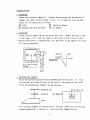
BAR GRAPH DISPLAY
The bar graph indicates the range of
the scale and remaining capacity with
a load. In the comparator mode, the
bar graph performs judgments.
- 7 -
<TO O O D,
<V
V 00000 M M
Zero point
M i QOODD 0CD3O
SoODD X 7 C
Scale range
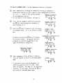
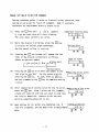
2. COUNTING SCALE MODE
The HG scale employs unique automatic memory renewal system, namely Simple
Self Counting System.
By this SCS, highly accurate reference unit weight will be obtained automatically, simply by adding optional number of samples (within three times
of that the display requires ).
COUNTING OPERATION BY SIMPLE SCS
Tare/Zero setting
0 PCs
(1) Place a container, if any, on
the scale and press the jjj key.
Verify that the display is "0".
LH (S
(2) Press the [fj key and release it
when U 5 E t appears.
Sampling start
U. SEt
Then a n I'lpcs appears. Press the U J key
to select quantity of samples to be loaded.
By every pressing of the LLj key, the
quantity will change as follows:
r
(4) Load samples of the quantity selected in
the display. Press the [T] key to memorize
unit weight of loaded samples temporarily.
Sample quantity selection
PCS
a n
U3 OS
mo
Unit weight memolizing
10 pcs
After a black out for a moment,
a quantity display and <J mark
starts blinking with a beep which
signs the memorization is over.
The blinking shows that the mode is
in unit weight improvement (sampling).
(5) Load optional quantity of samples
within tree times of the quantity
in the display. Then the unit
weight will be improved to that of the
total quantity of the samples loaded.
Beep will comes again.
E)
Automatic unit weight improvement
3 0 pcs
(6) Add. some more samples, but within
three times of the quantity displayed,
to improve accuracy of the unit weight.
Without any key operation, thus, the
unit weight will be improved by
increasing samples by and by repeatedly.
(7) At any sample quantity you want to finish,
pressing the j_Fj key will finish the
improvement operation. A beep comes
out and the display will turn to ordinary
counting mode.
Automatic unit weight
improvement
rvV .rVx )O
BS pcs
Improvement (sampling) finish
g c
O
NOTES
1. If sample quantity added is over three times of the displayed amount,
Sub
PCS will appear. Unload samples until the 5 u b PCS disappears.
2. In case the accuracy of memorized unit weight is unsatisfactory,
Rdd
_PCS will appear. Add samples until the R d d PCS disappears.
3. Under
S u b or Rdd
status, pressing the jT] key will memorise
unit weight for loaded samples. With such erroneous unit weight, counting
results may be incorrect.
4.
L -Err
appears with such sample which unit weight is less than
1/200,000 of the scale capacity. In this case, counting operation is
impossible with this scale, because the unit weight of the object is
lighter than specified.
- 9 -
3. PERCENT SCALE MODE
100% SETTING WITH REFERENCE SAMPLE
Percentage measurements by a reference sample as 100% memorizing in the
scale.
(1) Press the [ D key to indicate "0".
Tare/Zero setting
0
Also press the [T] key when use a
tare container.
L
(2) Press the |_FJ key until P SEh
appears.
M sign and some value will start blinking.
The value shows 100% reference value currently
set.
\
(S
o
Reference setting
SEt
P.
0.0 0 %
(3) Place a reference sample for 100% value on the
scale and press the L£J key.
After a black out for a moment, a beep
will come out to sign the memorization
of the value for 100%. Then the mode
turns to percentage measurement mode.
Unload the sample from the scale.
0.00 %
d3
ioD.no %
Percentage measurement
(4) Loading an object on the scale will
read the percentage to the reference
value memorized just before.
*
Reference memorizing
n n n v
u.U u %
mm
Division of measured percentage will vary according to the weight value
of the reference sample as 100% per capacity of the scale.
100% weiaht/scale caDacity
under 0.05%
0.05% —- under 0.5%
0.5 % -^y under 5 %
5 % ~ under 50 %
50 % and over
diSDlav division
L -Err
1 %
0.1 %
- 10 -
0.01
%
0.001
%
m
100% SETTING BY KEY OPERATION
Percentage measurements per 100% reference value set by key operation.
(1) Press the L L J key until P S E t appears.
Reference setting
p. set
M sign and some value will start blinking.
The value shows 100% reference value currently
m
set.
n n n v
u.u u A
(2)
Pressing the [73 key will display "0" and bar
Manual setting start
n v
graphs under it blinking, to start manual setting
m m
of the reference value for 100%.
(3) Pressing the [TJ key further will change the
Reference value
number of the last digit of the display in the
following sequence.
m m
«--Minus mark
r—
I
-=>
%
—i
I
Decimal point
(4) Pressing the G O key will shift the number at
the last digit of the display to the left.
Thus,
select optional number by the [7] key, then shift
Digit shifting
3D
m
it to the left by the [TJ key, and set a reference
value for 100% finally.
(5) After displaying the reference value, press the
IS I key to memorize the value.
A beep comes out and the mode turns to percentage
35 I %
E)
measurement mode.
*
Manual setting finish
The percentage display division will automatically vary as in the case
of SETTING WITH A REFERENCE SAMPLE, in page 10.
- 11 -
4.
CONVERSION SCALE MODE
In this scale mode, the scale displays a weight value of the load,
multiplied by a coefficient memorized in the scale.
With this function, the HG scale offers measurements in countless
weighing units.
OPERATION
Coefficient setting
(1) Press the J T ] key until C S E t appears.
C. SEt
M sign and some value will start blinking for
setting new coefficient.
m
The value blinking.
is the current coefficient in the memory.
(2)
Press the \Jj key. Display will show " 0 " and
n n n -u-
Coefficient setting
bar graph underneath will start blinking.
0 i
Now, it is ready to set the coefficient in
the display.
(3) Pressing the |_rj key further will change the
Setting first digit
number of the last digit of the display in the
following sequence.
^minus
mark
r
decimal point
Setting second digit
(4) Pressing the [_FJ key will shift the number at the
last digit of the display to the left.
10 t
Thus,
m
select optional number by the [Tj key, then shift
it to the left by the [ T ] key, and set a coefficient
value finally.
(5) After displaying the coefficient value, press the j_S_
key to memorize the value.
Setting finish
A beep comes out and
133 t
the mode turns to conversion mode.
(6) Load an object on the scale. The display shows
multiplied value of the load by the set coefficient.
Display value = Coefficient x Actual weight of
the object
- 12 -
m
Weighing
13 3.0 0 i
VARIOUS FUNCTIONS
FOUR BASIC FUNCTIONS
The HG scale has Accumulation and Comparator function in addition to the
high precision weighing function. In combination of these functions, it
offers four basic function complex as follows:
page
A. Precision Weighing Function : Simple display of weight data
7
B. Accumulation Function
: Display of sum of measured data... 15
C. Comparator Function
: Ranking display of judgments
16
D. Comparator + Accumulation
: Display of sum of judgment data... 16
* At the time of delivery, the function is set at above A, simple display.
HOW TO SELECT FUNCTIONS
In case the operation follows Selection of Scale Mode, start from
of
the followings.
Function setting
j j Press the L£J key for about 4 sec. and release
u n c
it when display shows Func
.
(no
o
\2) Then display changes to / SEh
the jT] key again to display 3
, , • Press
Scale Mode Selection
5 E L ,_, ,
/ SEh.
which shows the scale is in Function Setting Mode.
T ) Select a function by pressing the |Tj key which
changes the parameter according to the following
table.
ADVANCE TO
PAGE
DISPLAY
3
3
3
3
5
5
5
5
EL.
EL.
EL.
EL.
1
E
3
H
FUNCTIONS
Simple Weighing
Accumulation Display
Comparator Function
Accumulation + Comparator
7
15
14
14
m
m
Function setting mode
3
5 EL. i
m
3 5 E L. 3
a
3 5 E u. 3
3
(A)
m
5 EL. H
In case you selected Simple Weighing 3 5 E L. /or Accumulation Display
£? 5 5 L. 3 ' press the LSJ key to finalize the setting.
In case you selected Comparator 3 5 E L. 3 , or Comparator + Accumulation
3 5 E L. H , advance to the next page for setting judgment range.
- 13 -
SETTING OF JUDGMENT RANGE - In case Comparator Function is selected T ) After completion of selection of Comparator Function or Comparator +
Accumulation Function by (¥) in page 13, press the [T] key to display
El
£"•.__,, which is for setting contents
Comparator contents
of the comparator function.
5 I. aC. I
* For the details of the contents, see page 22.
T)
Jj
Fisrt, set the judgment condition by pressing
the Q J key, which changes the parameter by
every pressing of it.
Judgment condition
Press the LLJ key to advance to next Setting of
the Judgment Range. Set it by pressing the I T I
key.
Judgment range
5 I. La. I
m
5 5. L ,.
I
®
m
_Sele'ction of setting points
As aboves, pressing the 1 F I key will advance
the setting contents. Set at your optional
parameters by pressing the 1 T I key at any
stage and advance by the [fj key.
5 3. Pn. E
m
Beep control
. b u.
a
Setting of Contents
Judgment indication
0
5 5. LG.
(H
CD
) After completion of the setting of contents,
press the [sj key to Veturn to the measurement
mode.
Finish
0 PCS
GO
* If you want to set or verify parameters for
additional functions after 5 5 E L. mode,
press the \Vj key. See page 20 for additional
functions. At any stage, pressing the ]T] key
will return to the measurement mode.
- 14 -
ACCUMULATION FUNCTION
The Accumulation Function of the HG scale offers summing-up and display of
measured data repeatedly, usuful for mixing or filling.
OPERATION
(1) Load an object on the scale. After
stabilization mark ©appears, press
the 0 0 key to accumulate the display
value. The total amount will be seen
for a moment with H mark in the display.
Accumulation
100
pcs
(B
Total value
100
(2) Unload the object and allow the "0" display
is settled down with © mark. Then load
another object.
After stabilization, press the jTj key to
accumulate the value and display the total
for a moment as above (1).
* Loading and unloading should be done after
Q mark displayed for stabilization.
pcs
150
Accumulation
5SO
pcs
m
(3) To fix the total amount in the display,
press the \T] key. The total amount will
be displayed with the 2 mark.
To clear the accumulation to zero, press
the [jj key in this total displaying mode.
GO
m
Total amount
5 50
d3
PCS
©
m
NOTE
1. Pressing the |_SJ key for accumulation before settled down, ie, before
reading the © s i g n , the total value may be erroneous.
2. In the simple weighing mode, with weighin unit "B", the accumulation is
not effective. See page 7 and page 18.
3. To avoid duplication, following accumulation will not be effective unless
unloading the previous load, after once the LSJ key is pressed.
4. Or, instead of unloading, pressing thejT] key after accumulation by L P
will continue the accumulation with displaying "0". By this, you can
add next object on that still remaining on the scale. This is convenient
for mixing.
5. In the Counting mode, renewal of unit weight will automatically clear the
total.
- 15 -
COMPARATOR FUNCTION
SETTING WITH REFERENCE SAMPLE FOR JUDGMENT
Setting reference points (1 point to 4 points) with samples, read ranking
or bar graph for result of judgment.
Beep is available.
Convenient for
measurement within a preset value.
(1)
Press the £s_J key until \_ SEb
appears.
M sign and some value will start blinking.
Comparator function setting
L. 5Et
m
The value shows that currently set.
m
Setting start
*
Reference values should be:
1st point < 2nd point <
n n n „
3rd point < 4th point
Memorizing of 1st point
(2)
Load the sample for the 1st reference
point on the scale, and press the
key.
m
After a black out for a moment
a beep will
sound
m
to sign the
memorization of the set value with
displaying it. Then advance to the
Memorizing of 2nd point
2nd point setting.
(3)
5.0 0 8
Load the sample for the 2nd reference
point and press the [T] key.
will
sound
A beep
to memorize the value
/
H3
*
O
m
and advance to the setting of next point.
Finish of setting
(4) As above,
the
M
when settings are completed,
sign will disappear, and the
mode turns to measurement mode.
/_
1BR.008
LH E
B
NOTES
1. In case that only 1 point is selected to set, M sign will disappear and
setting will finish at above operation (2).
2. Such settins as 1st point^2nd point<:3rd point •& 4th point will be error.
3. In L
5 £ t mode, pressing the ULJ key enables to verify the set value.
4. Bars underneath will show every set points and judgment results.
for ranking display.
5. As to beep performance, see page 22 for beeps.
- 16 -
See page 18
MANUAL SETTING OF POINTS FOR JUDGMENT
Setting.reference points (1 point to 4 points) by key operation, read
ranking or bar graph for result of judgment. Beep is available.
Convenient for measurement within a preset value.
(1)
(2)
(3)
Press the |_SJ key until L SEb
appears.
M sign and some value will start blinking.
The value shows currently set value.
While the display is blinking, press the | T | key
to display "0" and bar graph underneath.
Now the manual setting is starting.
Pressing the [jj key further will change the last
digit of the display successively as follows.
Select an optional number.
• /"minus mark
Comparator function mode
SEb
L.
m
Setting start
L
Og
m m
Input of value
3g
r-
L
(4)
m
U3 IB
decimal point
Pressing the [?J key will shift the number at the
Memorizing of 1st point
last digit to the left. Set the second digit by
30g
pressing the LL) key. As such, shift by [T] key,
(3
ID
and set a number by the [T] key to complete setting
a value.
(5) After completion of setting value for the 1st point, Memorizing of 2nd point
press the [sj key. After a black out for a moment,
Ig
a beep will come out with the set value to sign that
the value is memorized. Advance to set the next
O
point by repeating above (2) to (5).
(6) When setting for all points are completed, the M
Finish of setting
3d Ig
sign will disappear, and the mode turns to measurement
mode.
m
- 17 -
m
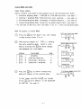
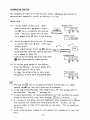
RANKING INDICATION OF JUDGMENT RESULT
1. Display of reference value at each set point
(Ex.)
mmcsmmammcmmcaaacaa
DDDGIi DDDCIf DDDDIt DDGGIt DDDDD ODDDD
1st
point
2nd
3rd 4th
point point point
In the L 5E t mode, pressing the [jsj key will read currently set
reference value at each point, which is shown by a bar at corresponding
position as in the above illustration.
2. Display of judgment result
When result is under the 1st point:
m m a u m a » m a m m a
m m ocoffl moDD
L
When result is between 2nd & 3rd point:
m m a m m a m u a m m a m m a m m a
DOOOD DGCCQ IHOO DDDDD DDDOO OODOQ
t f
2nd
3rd
point
point
point
BEEP SIGN OF JUDGMENT RESULT
See page 22.
SELECTION OF TWO WEIGHT UNITS
- continued from page 7, the column -
With the HG tuning-fork scale, you can weigh with two different or same
weight units, one in Mode A and the other in Mode B. For the contents,
see page 21 • From/to Mode A and Mode B, switchable by hitting [fj key.
1. Unit"kg", "g", "mg" and "ct" are indicated by character in the display.
Other weight units are indicated by ^ marks, upper in the display for
A mode, and lower in the display for B mode.
2. To change the weight unit, call n, I. ufl for mode A and 13. u.h
for mode B, after calling
Func
> referring to page 6,(7).
3. Contents for each parameters in 1 /, U_R
mode and 13. u,b mode,
refer to page 21.
4. All additional functions than ordinary weighing are effective only in mode
* In relation to above 2, sticking small stickers printed weight unit
*A.
may be convenient.
* Unit "3" is settable only in ORDINARY WEIGHING SCALE MODE.
- 18 -
VARIATIONS OF MEASUREMENT MODE in combination of functions
You can select any scale mode from the following l i s t in combination of
HG functions.
0 = effective
FUNCTION
MEASUREMENT MODE
SCALE
Remarks
MODE
unit
ORDINARY
g
WEIGHING
Z
q
PCS
COUNTING
z
pcs
MODE
q pcs
PERCENTAGE
MODE
0
Counting
0
0
-
0
-
0
0
0
0
-
0
-
A
B
0
-
A
Accumulation of pcs.
Unit weight
Percentage
s
MODE
Accumulation
0
-
%
Accumulation of %
Weighing
g
#
CONVERSION
0
Weighing
%
Conversion
#
g
A
B
A
B
Weighing
g
£
Accumulation! Comparator
function
Accumulation of Conv.
Weighing
B
Remarks : A - Ranking display is effective.
B - Ineffective with setting at COMPARATOR mode.
HOW TO VERIFY / CHANGE MODE
u nc
(1) Press the fT] key until F unc
(2)
/ SEt
appears.
/ w i l l appear first with set
parameter at the end of the display.
m
1
1
SEt,
i
5 SEL.
Pressing the LLJ key changes function
mode successively through 5
till
g
SEL
I
3
n.a
i
R.S.
i
5 rE.
3
B S.d.
3
,p ,
(3) By pressing the [ T J key, change the contents
of every mode by setting parameters at the
end of the display.
For contents of parameters,
H 1 uR
refer to page 2 0 .
B
»/=.
1
n
u
(4) Presssing [ T ] key will return the mode to the
original measurement mode.
DO.HBg
- 19 -
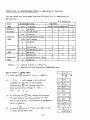
CONTENTS OF VARIOUS FUNCTIONS
PART I
•fr mark shows the status set at the shipping time.
FUNDAMENTAL
SCALE MODE
/
SBt
ADDITIONAL
FUNCTIONS
3
SSL
AUTO ZERO
3
RQ
AUTO SLEEP
W
RS
INTEGRATION
TIME
CONTENTS
Ordinary Weighing Scale (Weight Measurement only)
Counting Scale (Counting + Weight Measurement)
Percentage Scale (Percentage + Weight Measurement
Conversion Scale (Conversion + Weight Measurement
DISPLAY
FUNCTIONS
5
0
a
Ordinary Display
Advance to
3 RQ
Accumulation
Advance to
Comparator
3 I Pn
Comparator + Accumulation
Not effective
Automatically adjusts to ZERO point
Effective with
Not effective
battery option
Automatically turns display off
For small amount liquid measurements
Short
Quick
In a good measurement
condition
Long
Slow
In a disturbed
measurement condition
Quick
rf
Rough
STABILIZATION
6
Sd
Strict
WEIGHT UNIT
READABILITY
OUTPUT
CONTROL
1I
13
13
B
uR
dR
ub
db
See following page 21.
,F
\3
*
Slow
Output is not effective
Constant serial output (Old format, 6-digit)*, **
Constant serial output (New format, 7-digit)
CE type special format, satisfying EC norm. "/"
will be inserted before the last numeral digit.
Ex. + 0 1 2 3 . 4 5 / 5 sp q sp S CR LF
If set at B
iF I ,
B I a.c. for output control follows.
Advance to page 23, lower column, CONTENTS OF INTERFACE.
** For 6-digit format, see page 28, 29.
*** When the function lock (switch inside) is effective, ie, in CE mode, the
settings for the output are held as set when the lock was open.
- 20 -
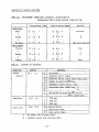
PART I - 2
VARIOUS WEIGHT UNITS & READABILITY SELECTION (Function 71 to 74)
FUNCTIONS
CONTENTS
DISPLAY
•
/
i 3
\ 3
WEIGHT UNITS
GROUP "A"
1 1 uR
*
LEAST
READABILITY
mg
g
kg
ct
j5
oz
IS
/
1b
FT ne
Ex.HG-2000
3
HE
0.01g
0.02g
dR
0.05g
..„.
0.1 g
"s"
a
WEIGHT UNITS
GROUP " B "
( Unit
"B 1
13
ub
is settable only
n
ORDINARY WEIGHING MODE.)
*
LEAST
READABILITY
1H
db
Co a r s e
0.2 g
No u n i t
i
mg
3
3
g
kg
H
ct
5
oz
5
"Ib
/
c
Fin e
displayed
Ex. HG-2000
°-01g
0.02g
3
O.OSg
W
0.1 g
c
Co arse
0.2 q
* When the function lock (switch inside) is effective, ie, in CE mode, the
settings for the least readability are held as set when the lock was open.
- 21 -
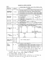
CONTENTS OF VARIOUS FUNCTIONS
PART II
CONTENTS OF COMPARATOR FUNCTIONS (Function 21 to 25)
In case the scale is set in the Comparator Mode 3 5 E L 3 or E S S L H
following functions will be displayed before displaying 3 R Q <_, .
FUNCTIONS
JUDGEMENT
CONTROL
DISPLAY
3I
r=*
JUDGEMENT
RANGE
EE
L ,r
/
E
.un
i
i
.1
SETTING
POINTS
DPJ
C
D n
r
E
:3
.a
a
EH
BEEP
CONTROL
*1
bu
i
3
3
H
5
a
JUDGEMENT
INDICATION
ES C C *
1
E
CONTENTS
Constant judgement, even data is unsettled.
Judgement after data has settled down.
No judqment around zero poi nt.
Judges for all range
1 point setting
ES L 0 E unsettable
M
settable
2 points setting
If
unsettable
3 points setting
11
unsettable
4 points setting
Zone Division
OFF, no beeps
ON in zone (a)
Zone (a)
1st pointON in zone (b)
2nd
pointON in zone (c)
Zone (b)
ON in zone (a) + (b) 3rd pointON in zone (b) + (c) 4th pointON in zone (a) + (c)
Zone (c)
Ranking display
2-point bar graph, effective in 2-point setting.
TI
t1
*1. Setting points and beeo status
Set Point • • •
••• 1 s t
•
-
'
—
:
•H—f"_c
1 Point Setting
—
1st
Set Points • •
-
2nd
/ •
2 Points Setting
•
—
—
:
:
r
—— -
-3-
Set Points .
-3-
1st
2nd
3rd
3 Points Setting
Li '
-5"
Set Points-•
1st
2nd
3rd
:
— ;'4 Points Setting
4th
. r_
r-
-5- 22 -
•
.—£
-
CONTENTS OF VARIOUS FUNCTIONS
PART III
MEASUREMENT CONDITIONS & RESULTS, IN RELATION TO
INTEGRATION TIME & STABILIZATION SPEED SETTING
Integration Time
Conditions
Good
S rE
5 Sd W
1
1
Normal
S rE
i
B Sd
3
i
No good
Measurement
Precise
S rE
H
S
L/
Normal •
i
Coarse
S rB
S Sd
r E
I
B Sd 1
$
B Sd 3
3
i
5
3
I
I
i
PART IV
r E
Stabilization Speed
1
B Sd H
1
Results
Accurate
i
Not very accurate
Slow
I
Quick
CONTENTS OF INTERFACE
CONTENTS
No output
0
a : a c
I
Constant serial output
3 Constant serial output when stabilized.
3 Output by pressinq C D key.
'-/ Automatic output with a load.
5 One output when stabilized. *1
S
*?
One output by pressinq fs| key but
1
after stabilized.
I
1200 bps
Baud Rate
B E fa L
2400 bps
J 4300 bps
un
No parity bit
8 3 P.R.
Parity Bit
i
i
Odd parity check
E Even parity check
*1 : No output with unstable data.
*2 : Constant output with unstable data.
FUNCTIONS
Output
Control
DISPLAY
•3
- 23 -
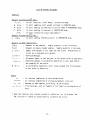
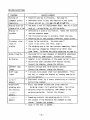
LIST OF VARIOUS MESSAGES
DISPLAYS
Appears by pressing [7] key :
Func
: To call functions, scale modes, calibration mode.
U. SEt
'• To start sampling (unit weight setting) in COUNTING mode.
P- SEt
• To start setting of reference value for 100% in PERCENTAGE mode.
C. SEt
: To start setting of constant in CONVERSION mode.
CRL
: To start calibration (span adjustment).*
Appears by pressing | s | key :
L 5Et
: To start setting reference points in COMPARATOR mode.
Appears by other operations :
R d d
: Request to add samples. Sample quantity is not sufficient.
Sub
: Request to reduce loaded samples. Sample quantity is too many.
L -Err
'• Sample unit weight is too light for the scale. Unavailable to
to set as a reference unit weight.
a - E r-r
: Overload message.
\-£
: Erroneous input, or not set yet, or 1st point value ;> End point.
: Reference weight in calibration operation is less than 50% of
the capacity of the scale.
: In calibration operation, error value exceeds the 1% tolerance,
or the scale is defective.
r r
3-Err
BEEPS
—
—
—
—
—
—
:
:
:
:
To indicate completion of data accumulation.
To indicate completion of storing parameters to be set.
Request to add samples, with Rdd
H pcs display.
Error message, such as "Sample is too light",or misoperation of
keys.
* When the function lock (switch inside) is effective, ie, in CE mode, the
CAL function is locked to unavailable to calibrate the scale.
- 24 -
TROUBLESHOOTINGS
SYMPTOMS
Setting of
judgment points
impossible
Display does not
chanae with a loa
i
Display is
unstable
Erroneous value
reads in
display
Wrong linearity
No display
LOW-BATT lamp
lights
SLEEP lamp
lights
b-Err
appears
Unavailable
weighing upto
the capacity.
a ~E r r
appears
u ~ E r~ r
appears
CAUSES & REMEDY
* Function setting is erroneous. See page 13.
* Reference value is over the capacity of the scale.
* Values are set as : 1 s t - ^ 2nd ^ 3rd ^ 2 " 4th
* The mode is not in a measurement mode. May be in such
mode as : accumulation, or setting modes.
* Affected by a wind or oscillation. Check the location
and the response speed.
* The installation base is unstable. Check the base.
* Weighing pan or tare touches something. Check around.
* Wrong taring operation. See page page 7.
* Scale is not level. See level, page 5.
* The weighing pan or the tare touches something. Check.
* The span has chnaged by relocation or after long
time lapse. Calibrate the scale referring to page 26 .
* Characteristics have changed, or mechanism adjustment
• has changed by some reason. Contact the shipper.
* Adaptor is not connected, or the power switch is OFF.
* Battery has been consumed (with battery option).
Connect the adaptor, charge the battery.
* Battery voltage drop (with battery option).
Connect the adaptor, charge the battery.
* 3 minutes have passed after last measurement. Press
any key, or change the display by loading some (with
battery ODtion).
* Electronic error, by a static electricity or a noise.
Contact the shipoer.
* Gross load weight exceeds the scale capacity.
Weighing range = Full weighing range - Tare value
* Weighing range has changed by some damage on the
weighing mechanism. Contact the shipper.
* Something contacts the weighing pan to lift it.
* The balance of the mechanism has changed by some
reason. Contact the shipper.
*
Check i f the lock is opened.
- 25 -
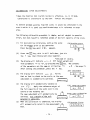
CALIBRATION
(SPAN
ADJUSTMENT)
* When the function lock (switch inside) is effective, ie, in CE mode,
Calibration is unavailable
by the user.
Contact the shipper.
To achieve optimum accuracy from the scale, it should be calibrated in the
area in which it is used, and recalibrated when it is relocated to other
area.
The following calibration procedure is simple, and not subject to operator
errors, but does require a reference weight of the full capacity of the scale.
(1) For most precise calibration, warm up the scale
Calibration start
for 30 minutes prior to the operation.
CRL
Press t h e [_FJ k e y unitl C R L appears.
(2) Press the jjj key, with it still held down, just hit
the
F
key, then release both keys together.
*See page 27 middle.
(3) The display will indicate u <-< / t
• * Select weight unit
from parameters "1" to "d", by pressing the [T | key. The contents
of the parameters are the same as at function 1 I
u
R
. See page 21.
After setting the parameter, press the F key.
(4) The display will indicate
a n
Zero adjustment
un
o n
Q . Verify
that no load is placed on the scale, as the zero
adjustment is automatically achieved.
cu
a
/
(5) The display will automatically advance to
an
F5
•
Full range adjustment
Apply the reference weight of
a n
the full capacity of the scale just in the
F.5
centre of the weighing pan.
Under auto-calibration
The span adjustment will automatically be
achieved.
Use a weight of the unit
Z""1
\
a n
F.5
selected in above (3).
When the calibration is completed, the display
will automatically return to the measurement
mode.
L
- 26 -
Js>
Calibration finish
n n Un g,-.
Dc un un u.u
NOTES
1. To stop the calibration operation, press the [s_] key.
2. a ~Err
signs that the reference weight is over the full capacity.
3. The calibration is available with a reference weight of over 50% of the
scale capacity. Nevertheless, we recommend to adjust by a full capacity
weight. I-Err
will appear if the load is less than 50% of the capacity.
4. £ - £ r r
w-j]i appear if the error exceeds 1% of the capacity, or any
other object than a reference weight. Or, perhaps the scale is defective.
Contact the shipper.
* From page 26 u o it • will not appear in setting at
I SEt
! and
at tne same
13
u h u
time. The display will advance to an
u
In this case, use a reference weight of the weight unit selected in
function q /
BATTERY OPTION
Charge hours
Operation hours
Auto-Sleep
Low Battery
(NiCd battery pack)
Approx. 8 hours under power switch of the scale "OFF".
Approx. 5 hours continuous operation without output.
Sleeps 3 minutes after last operation, for power saving.
L0W-8ATT lights on when the voltage falls under the
specification.
- 21 -
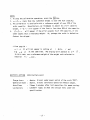
OUTPUT FORMAT
VIBRA HG s c a l e
provide
a serial
data
transmission
output.
These signals are t r a n s m i t t e d by DIN type 8-pin connector on the rear panel
of the s c a l e .
Pin 1
Pin
Pin
Pin
Pin
4 Transmitted Data Line
2
5 Signal Ground
3
Only Pin 4 and Pin 5 are used for the scale's data transmission as shown by
above illustration.
Other pins are unavailable, because they are occupied by the scale circuit.
CONTENTS OF THE TRANSMITTED DATA
8-bit words (ASCII standard character codes), 1 start bit, 2 stop bits and
0 or 1 parity bit.
Each time data is transmitted, the SHINKO scale sends a string of 14 or 15
characters as follows: + or - sign, 6 or 7-digit display reading & decimal
point( = 7 or 8 characters together), two unit symbols, two status symbols,
one carriage return, and one line feed.
P
0
U
S
: Polarity
: Data
: Unit Symbol
: Status Symbol
P, D, D, D, D, D, D, D, U, U, S, S, CR, LF
1 character (+ or -)
7 characters, or 8 characters
2 characters (sp G or KG for example)
2 characters (sp) S... Data is stabilized
(sp) U
Data is not stabilized
(sp) E....Error data
CR : Carriage Return
LF : Line Feed
A TYPICAL STRING
eg. 123.4 g = +, 0, 0, 1, 2, 3, ., 4, sp, G, sp, S, CR, LF
eg. -65.4321 kg
= -, 6, 5, ., 4, 3, 2, 1, K, G, sp, U, CR, LF
In these examples, sp represents a blank (ASCII #40, octal), CR represents a
carriage return (ASCII #15), and LF represents a line feed (ASCII #12).
- 28 -
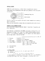
ASCII CODES (EXTRACTION)
Complete, listings of the ASCII codes are available, but the following list
will be limited to those codes used in SHINKO scales.
Octal
Code
12
15
40
53
55
56
60
61
Octal
Code Decimal
Decimal Hexadecimal Character
50
LF Line Feed 62
OA
10
51
OD CR Carriaae Ret . 63
13
52
sp Space Bar 64
20
32
+
65
53
23
43
54
66
2D
45
67
55
2E
46
70
56
0
30
43
57
1
71
31
49
Hexadecimal Character
2
32
33
34
35
36
37
38
39
3
4
5
6
7
8
9
OTHER SPECIFICATIONS
Transmission Method
Baud Rate
Signal Level
Serial Data Transmission
1200 bps, 2400 bps, 4800 bps selectable, see page 23.
TTL level
- 29 -