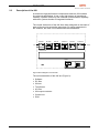
1
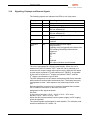
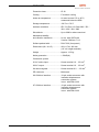
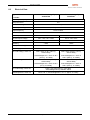
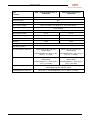
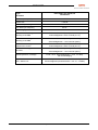
Operating Instructions
"UniVert 2" inverter
and SBS option
AEG Power Supply Systems GmbH
Department: PPSD TED
Name:
Gleitsmann/Schenuit
Revision:
01
Date:
06.08.2008
Operating Instructions
8000012364 BAL, en
"UniVert 2" inverter
Notes on these Operating Instructions
Duty to Provide Information
These operating instructions must be read carefully by all persons
working with or on the inverter system prior to installation and initial
start-up.
These operating instructions are a composite part of the inverter
system.
The operator of this unit is obliged to make these operating
instructions available to all personnel transporting or starting up units,
or performing maintenance or any other work on the unit.
Validity
These operating instructions comply with the current technical
specifications of the inverter system at the time of publication. The
contents do not constitute a subject matter of the contract, but serve
for information purposes only.
AEG reserves the right to make modifications with regard to contents
and technical data in these operating instructions without prior
notification. AEG cannot be held liable for any inaccuracies or
inapplicable information in these operating instructions, as no
obligation to continuously update the data and maintain their validity
has been entered into.
Warranty
Our goods and services are subject to the general conditions of
supply for products of the electrical industry, and our general sales
conditions. We reserve the right to alter any specifications given in
these operating instructions, especially with regard to technical data,
operation, dimensions and weights. Claims in connection with
supplied goods must be submitted within one week of receipt, along
with the packing slip. Subsequent claims cannot be considered.
AEG will rescind all obligations such as warranty agreements, service
contracts, etc. entered into by AEG or its representatives without prior
notice in the event of maintenance and repair work being carried out
with anything other than original AEG parts or spare parts purchased
by AEG.
Handling
These operating instructions are structured so that all work necessary
for start-up, maintenance and repair of the units can be performed by
qualified personnel.
Illustrations are provided to clarify and facilitate certain steps.
If danger to personnel and equipment cannot be ruled out in the event
of certain work, it is highlighted accordingly by pictograms explained
in chapter 1, Safety Instructions.
Page 2 of 42
8000012364 BAL, en
"UniVert 2" inverter
Abbreviations
The following abbreviations are used in these instructions:
INV
= Inverter
SBS = Static Bypass Switch
DOU = Display and Operation Unit
SMPS = Switch Mode Power Supply
PSM = Power Supply Monitoring
Hotline
Do you have any suggestions for improving these operating
instructions?
Do you have any questions on any of the subjects dealt with in these
operating instructions?
Our service department is available on the hotline number given
below:
AEG Power Supply Systems GmbH
Emil-Siepmann-Straße 32
D-59581 Warstein
Germany
++49 (0) 29 02-763-100
FAX:
++49 (0) 29 02-763-645
E-mail: Service-Be.AEG@powersupplysystems
http://www.aegpss.de
Copyright
No part of these operating instructions may be transmitted,
reproduced and/or copied by any electronic or mechanical means
without the express prior written permission of AEG Power Supply
Systems GmbH.
©
Copyright AEG Power Supply Systems GmbH 2003. All
rights reserved.
Page 3 of 42
8000012364 BAL, en
"UniVert 2" inverter
Table of Contents
Notes on these Operating Instructions ...........................................2
1
1.1
1.2
1.3
1.4
1.5
1.6
1.7
1.8
Safety Instructions!................................................................6
Important Instructions and Explanations ..................................6
Accident Prevention Regulations .............................................6
Danger during Maintenance and Repair Work.........................7
Qualified Personnel..................................................................7
Safety Awareness ....................................................................8
Application ...............................................................................8
Liability .....................................................................................9
Directives .................................................................................9
2
2.1
2.2
2.3
2.4
2.5
2.6
General Information .............................................................10
System Description ................................................................10
Function of the System ..........................................................11
Description of the INV ............................................................13
Principle of Operation of the INV, Electrical ...........................14
Description of the SBS ...........................................................15
Principle of Operation of the SBS, Electrical..........................16
3
3.1
3.2
3.3
3.4
3.5
3.6
3.7
3.8
3.9
3.10
Function of the Inverter .......................................................17
DC Input .................................................................................17
AC Output ..............................................................................17
DC Input Monitoring System ..................................................17
Temperature Monitoring System............................................17
Output Voltage Monitoring System ........................................17
Monitoring of Functions..........................................................17
ON/OFF Switch ......................................................................18
CAN Bus Interfaces X6 / X7...................................................18
DIL Switch ..............................................................................18
Signalling, Displays and Remote Signals...............................20
4
4.1
4.2
4.3
4.4
4.5
4.6
4.7
4.8
4.9
4.10
4.11
4.12
4.13
Function of the SBS (optional) ...........................................21
Operating Statuses ................................................................21
Switchback Attempts..............................................................21
AC Mains Input (X1)...............................................................22
AC Busbar (X2) ......................................................................22
AC Mains Monitoring System.................................................22
AC Busbar Monitoring System ...............................................22
Temperature Monitoring System............................................22
Monitoring of Functions..........................................................22
Reset Button ..........................................................................22
CAN Bus Interfaces (X6, X7) .................................................23
DIL Switch ..............................................................................23
Signalling, Displays and Remote Signals (X4).......................24
Operating modes ...................................................................25
5
5.1
5.2
5.3
5.4
Start-Up .................................................................................27
Installation ..............................................................................27
Connection .............................................................................27
Connecting the Loads / DC / Mains .......................................27
Disconnection ........................................................................28
Page 4 of 42
8000012364 BAL, en
"UniVert 2" inverter
6
Maintenance .........................................................................29
7
7.1
7.2
Troubleshooting...................................................................30
No Output Voltage or Output Current Present
(with connected load) .............................................................30
Output Voltage Deviation .......................................................30
8
8.1
8.2
8.3
Technical Data......................................................................31
General Data INV...................................................................31
General Data SBS..................................................................33
Electrical Data ........................................................................36
9
Dimensional Drawing...........................................................40
Page 5 of 42
8000012364 BAL, en
"UniVert 2" inverter
1
Safety Instructions!
1.1
Important Instructions and Explanations
The instructions for operation and maintenance, as well as the
following safety regulations must be complied with to ensure the
safety of personnel as well as the availability of the unit. All personnel
installing/dismantling, starting up, operating or servicing the unit must
be familiar with and observe these safety regulations. Only qualified
personnel may perform the described work using tools, equipment,
test equipment and materials intended for the purpose and in perfect
working condition.
Important instructions are highlighted by "CAUTION:",
"ATTENTION:", "NOTE:" and indented text.
CAUTION:
This symbol identifies all working and operational procedures
requiring absolute compliance to avoid any danger to personnel.
ATTENTION:
This symbol identifies all working and operational procedures
requiring absolute compliance to prevent any damage, irreparable
or otherwise, to the INV or its components.
i
1.2
NOTE:
This symbol identifies technical requirements and additional
information requiring the operator's attention.
Accident Prevention Regulations
Compliance with the accident prevention regulations valid in the
respective country of use and the general safety regulations in
accordance with IEC 364 is mandatory.
The following safety regulations must be observed prior to any work
on the inverter system:
• disconnect the power supply,
• secure against reactivation,
• verify that the unit is disconnected from the power supply,
• earth and short-circuit the unit,
• cover or isolate any neighbouring live parts.
Page 6 of 42
8000012364 BAL, en
"UniVert 2" inverter
1.3
Danger during Maintenance and Repair Work
CAUTION:
The voltages applied to the INV can be fatal. Prior to start-up
and/or maintenance work always disconnect the INV from the
power supply and ensure that the unit cannot be switched on.
The capacitors must be discharged. Free-standing and movable
components can protrude into the work area and cause injuries.
ATTENTION:
Considerable damage can be caused to equipment if unsuitable
replacement parts are used during repair work, if work is carried
out by unauthorised personnel, or the safety regulations are not
observed.
i
1.4
NOTE:
Only trained and qualified personnel may work on or in the vicinity
of the INV (refer to chapter 1.4) while strictly observing the
safety regulations.
Qualified Personnel
The inverter system may only be transported, installed, connected,
started up, serviced and operated by qualified personnel who are
familiar with the pertinent safety and installation regulations. All work
performed must be inspected by responsible experts.
The qualified personnel must be authorised by the responsible safety
officer of the installation to perform the work required.
Qualified personnel is defined as personnel
• having completed training and gained experience in the respective
field,
• familiar with the pertinent standards, rules and regulations and
accident prevention regulations,
• having received instruction on the mode of operation and operating
conditions of the inverter system,
• capable of recognising and preventing dangers.
Regulations and definitions for qualified personnel can be found in
DIN 57105/VDE 0105, Part 1.
Page 7 of 42
8000012364 BAL, en
"UniVert 2" inverter
1.5
Safety Awareness
The qualified personnel defined in chapter 1.4 are responsible for
safety. They are also responsible for ensuring that only suitably
qualified persons are permitted access to the INV system or the
safety area.
The following points must be observed:
All working procedures are prohibited which are detrimental to the
safety of persons and the function of the INV system in any way.
The INV system may only be operated in perfect working condition.
Never remove or render inoperable any safety devices.
All necessary operational measures must be initiated prior to
deactivating any safety device for performing maintenance, repair or
any other work on the unit.
Safety awareness also entails informing colleagues of any unsuitable
behaviour and reporting any faults detected to the respective
authority or person.
1.6
Application
The INV system has been designed for installation in a power supply
cabinet and may only be used for uninterrupted power supply in the
described installation position and operating mode while observing
the maximum permissible connection values as given in these
operating instructions. The unit may only be used for this intended
purpose. It is not permitted to make any unauthorised modifications to
the INV or to use any spare parts and replacement parts not
approved by AEG SVS or to use the INV system for any other
purpose.
The person responsible for the installation must ensure that:
• the safety regulations and operating instructions are readily
available and are complied with,
• the operating conditions and technical data are observed,
• safety devices are used,
• the prescribed maintenance work is performed,
• the maintenance personnel is informed without delay or that the
INV system is shut down immediately in the event of abnormal
voltages or noise, high temperatures, vibrations or any similar
effects, in order to detect the cause.
These operating instructions contain all information required by
qualified personnel for operation of the INV system. Additional
information and explanations for unqualified persons and for the use
of the INV system in non-industrial applications is not included in
these operating instructions.
The warranty obligations of the manufacturer are only applicable if
these operating instructions are observed and complied with.
Page 8 of 42
8000012364 BAL, en
"UniVert 2" inverter
1.7
Liability
No liability is accepted if the inverter system is used for applications
not intended by the manufacturer. Any measures necessary for the
prevention of injury, or damage to equipment is the responsibility of
the operator or user. In the event of any claims in connection with the
unit, please contact us quoting:
• type designation,
• works number,
• reason for claim,
• period of use,
• ambient conditions,
• operating mode.
1.8
Directives
The units comply with current DIN and VDE regulations. VBG4 is met
on the basis of compliance with VDE 0106 Part 100.
The requirements of VDE 0100 Part 410, "Functional extra-low
voltage with safe isolation", are complied with when applicable.
The CE sign on the unit confirms compliance with the EC outline
directives for 73/23 EEC – Low voltage and for 89/336 EEC –
Electromagnetic compatibility if the installation and start-up
instructions described in the operating instructions are observed!
Page 9 of 42
8000012364 BAL, en
"UniVert 2" inverter
2
General Information
2.1
System Description
Depending on the system design, the following versions of safe
AC power supply are possible (Figure 1):
• Individual INV operation
• Parallel operation of several INVs
• Individual or parallel operation with SBS
DC
INV
=
~
AC load
Individual operation
DC
INV
INV
=
Bus termination
INV
=
CAN bus
=
~
~
Bus termination
~
AC load
Parallel operation
DC
INV
Bus termination
AC mains
INV
=
INV
=
~
SBS
CAN bus
=
~
~
Man. bypass
Parallel operation with SBS
AC load
Figure 1 Block diagrams of various systems
Page 10 of 42
8000012364 BAL, en
"UniVert 2" inverter
Individual INV operation:
Here an INV is supplied with DC and itself supplies the AC load. In
the event of INV fault or switch-off, the load is no longer supplied.
Parallel INV operation:
In order to increase redundancy or performance, up to 8 INVs of the
same type and the same output can be connected in parallel. Note
that if one or several of the INVs fail, the remaining INVs take over
the load. Overload of the remaining INVs can be prevented by
choosing the right number of redundant INVs. If the number of INVs
that fail or are switched off exceeds the number of available
redundant INVs, the remaining INVs switch off together.
When the INVs are switched back on by connecting the DC, they do
not switch on their output contactors at the same time until a sufficient
number of INVs (in accordance with the redundancy setting) are
available to take over the load.
INVs for parallel operation need a choke between INV output and
busbar.
Individual or parallel operation with SBS:
If one or more INVs are combined with an SPS, switchover of the
loads from the mains to the INV and vice versa is possible without
any interruption. With parallel operation systems, the load is
distributed to the remaining INVs if one or several INVs fail. The
system may switch over to the mains when a voltage drop occurs on
the load busbar as a result of the failure of one INV, or if the number
of INVs still operating is insufficient (redundancy setting). In order to
switch the load back from the mains to the INVs, n-R INVs must be in
operation (where R = redundant INVs).
2.2
Function of the System
Individual INV operation:
The INV as an individual unit supplies the loads. If it is switched off or
disturbed, either by internal faults of the INV or by failure of the
DC supply or by a DC voltage deviation, the AC loads are no longer
supplied. The INV is not synchronised with the mains or other
AC voltage sources. The INV can be connected to the DC voltage
using a switching device on the input (miniature circuit-breaker,
contactor). An internal softstart device limits the current to values
below the rated current. If the INV is switched to the DC, the control
unit starts operating. The INV supplies the output voltage if the unit is
additionally switched on using the ON/OFF switch. If the supplying
mains fails, the battery of the power supply system is discharged
(also) by the INV. When the DC undervoltage monitoring value is
reached, the INV is switched off. If the battery is charged after the
mains voltage has returned, the INV is automatically started when a
limit value of the DC undervoltage monitoring is exceeded.
Page 11 of 42
8000012364 BAL, en
"UniVert 2" inverter
Parallel INV operation:
Prerequisite for parallel operation is that the INVs on the DC and AC
side are connected in parallel, interconnected via CAN bus (16-pin,
X7) and correctly addressed. The general behaviour of an individual
INV is as described in the previous paragraph.
The loads are only supplied with voltage when n-R INVs are switched
on. The K7 output contactors of the INVs switch on simultaneously.
The load is distributed equally to all the INVs in operation. If an INV is
switched off or becomes faulty, the remaining INVs supply the load.
The INVs are not synchronised with the mains.
When the DC undervoltage monitoring value is reached, the INVs are
switched off. If the battery is charged after the mains voltage has
returned, the INVs are automatically started when a limit value of the
DC undervoltage monitoring is exceeded. The K7 output contactors of
the INVs are switched on when n-R INVs are in operation.
In order to be able to remove one INV from the interconnected
system for maintenance or repair work, we recommend providing a
DC and an AC fuse for each INV.
Individual or parallel operation with SBS:
Prerequisite for operation with SBS is that the INV and SBS are
connected in parallel on the AC side, interconnected via
CAN bus (X7) and correctly addressed. The general behaviour of an
individual INV is as described in the two previous paragraphs.
Under normal conditions, the INVs are operating synchronously with
the mains and supply the AC loads. In the event of a voltage drop on
the load busbar caused by the short circuit of an AC load or the
failure, switch-off or overload of the INVs, the thyristor contactor of
the SBS is fired and the K7 output contactors of the INVs are
switched off. The loads are supplied by the mains. When the required
number of INVs is available again, the loads are switched back from
the mains to the INVs without interruption. If the SBS is blocked, e.g.
because of mains voltage deviations, it is not possible to switch from
INV to mains or vice versa.
In order to be able to disconnect the SBS from the mains and the
AC busbar for maintenance or repair work, we recommend providing
an AC fuse for both sides and supply the loads via the manual
bypass.
Page 12 of 42
8000012364 BAL, en
"UniVert 2" inverter
2.3
Description of the INV
Its electronic high-performance components make the INV suitable
for universal applications. It has a very high degree of operational
reliability, optimum efficiency and excellent communication capability
with other systems thanks to integrated interfaces.
The control electronics of the INV have been designed on the basis of
state-of-the-art microcontroller technology. By using parameters in
the software, the main unit characteristics are determined.
Softstart
DC filter
INV set
Transform.
AC filter
Contactor
Load
DC
Control unit
DOU
U = 231V
I = 10.3A
INV
Figure 2 Block diagram of the inverter
The main assemblies of the INV are (Figure 2):
• Softstart
• DC filter
• INV set
• Transformer
• AC filter
• INV output contactor
• Control unit
• DOU
Page 13 of 42
8000012364 BAL, en
"UniVert 2" inverter
Figure 2 illustrates the principle of an INV.
In normal operation, the load is supplied "Online" by the INV. With
systems comprising several parallel INVs, the load current is divided
in accordance with the number of INVs. Depending on the system
design, a power supply using up to 8 INVs can be realised. In addition
to the parallel operation of several INVs, the reliability of supply can
be further increased by integrating a static bypass switch, SBS. In the
event of a failure of several INVs, switchover to the mains takes place
without any interruption. Apart from power cabling, a bus line is
required for control purposes between the units for systems
comprising several INVs (and SBSs). The bus line has to be
terminated at both ends with a resistor.
ATTENTION:
This INV must not be connected in parallel to the mains on the output
side!
2.4
Principle of Operation of the INV, Electrical
After connection of the DC voltage, the DC filter capacitors are
charged via the softstart device. The control unit activates a bridging
contactor as soon as the capacitor charging process is finished. The
DOU displays measured values (output voltage/output current) on the
LCD and the unit status via LEDs. The INV is switched on using the
ON/OFF switch on the DOU. When the INV has been switched on, it
can be started or stopped by connecting or disconnecting the
DC voltage supply.
The transistor INV set, pulsed with approx. 20 kHz, transforms the
direct voltage into a single-phase sinusoidal AC voltage. The voltage
is transformed electrically isolated to the required AC output voltage
using a transformer. The secondary voltage is led to the load
terminals via the AC filter, a miniature circuit-breaker, a current
transformer and the INV output contactor. The stabilised output
voltage of the INV is short-circuit-proof and can supply loads from
capacitive through ohmic to inductive, as well a non-linear loads with
a high crest factor. The INV also supplies high starting currents for
motor loads. Refer to chapter "Technical data" for the exact
specifications. The entire control and monitoring process is carried
out using a microprocessor. LEDs and relays show the unit status,
whilst output voltage and output current are displayed on an LCD.
INVs for parallel operation need a choke between the INV output and
the busbar. When several INVs are operated in parallel, or one or
more INVs are operated with an SBS, a CAN bus is required between
the units for control purposes. An additional CAN bus allows the unit
to be integrated in a power supply system and connected to a central
control and monitoring unit (PSM).
With individual units, the INV immediately starts after actuating the
ON/OFF switch. With an INV with SBS and presence of the mains,
the INV starts immediately, but the output contactor is only switched
on after synchronisation with the mains. With systems comprising
several INVs, these synchronise to the mains and then jointly switch
on the output contactor. The INV can be switched off in every
operating status without delay using the ON/OFF switch.
Page 14 of 42
8000012364 BAL, en
"UniVert 2" inverter
2.5
Description of the SBS
Its electronic high-performance components make the SBS highly
overload-resistant and thus capable of quickly eliminating load short
circuits.
The SBS can be used as the central SBS for parallel operation of up
to 8 INVs.
Another outstanding characteristic of the SBS is its communication
capability with other systems via integrated interfaces.
The control electronics of the SBS have been designed on the basis
of state-of-the-art microcontroller technology. By using parameters in
the software, the main unit characteristics are determined.
SBS set
AC
Load
Control unit
DOU
U = 231V
I = 10.3A
SBS
Figure 3 Block diagram of the SBS
The main components of the SBS are (Figure 3):
• Thyristor set
• Control unit
• DOU
Figure 3 illustrates the principle of an SBS.
In normal operation, the SBS is not fired, the load is supplied "Online"
by the INV or INVs. If the supply of the load is no longer guaranteed
by the INVs or the load voltage has dropped below a permitted value
due to a load short circuit, the load is switched over to the mains
without interruption.
Apart from power cabling, a bus line is required for the SBS for
process control purposes between the INV/INVs and the SBS. The
bus line has to be terminated at both ends with a resistor.
Page 15 of 42
8000012364 BAL, en
"UniVert 2" inverter
2.6
Principle of Operation of the SBS, Electrical
If the SBS is supplied by connecting the mains or the load voltage,
the corresponding operating status is automatically activated after
3 to 5 seconds.
With mains operation, the DOU displays load voltage and SBS
current. With all other operating statuses, in addition to the load
voltage the corresponding status (ready, blocked, fault) is displayed.
The toggle switch on the DOU serves exclusively to acknowledge
SBS faults.
The SBS control unit continually monitors the load voltage and, in the
event of a load voltage deviation, initiates switchover of the loads
from the INV/INVs to the SBS without interruption. Then the loads are
automatically switched back to the INV/INVs. The thyristors of the
SBS only quench when the supply of the loads is guaranteed by the
activation of the output contactors of the INV/INVs.
When the SBS is fired, both antiparallel thyristors are triggered over
the whole period ensuring reliable operation of the SBS in the entire
range from inductive to capacitive load.
The entire control and monitoring process is carried out using a
microprocessor. LEDs and relays show the unit status, whilst the
output voltage and output current are displayed on an LCD. If the
SBS is operated with one or more INVs connected in parallel, a CAN
bus is required between the units for control purposes. An additional
CAN bus allows the unit to be integrated in a power supply system
and connected to a central control and monitoring unit (PSM).
Page 16 of 42
8000012364 BAL, en
"UniVert 2" inverter
3
Function of the Inverter
For technical data or unit settings, refer to the Technical Data Sheet
in chapter 8.
3.1
DC Input
The inverter is operated with 48 V (or 60 V) DC voltage. The input
voltage is fuse-protected outside the INV. For details, refer to the
technical data.
An integrated softstart device limits the making current of the inverter
to a value smaller than the rated input current. The input voltage is
continuously monitored. (See chapter 3.3.)
3.2
AC Output
The INV output voltage is regulated to 230 V 50 H (see chapter 3.9)
and monitored (see chapter 3.5). With an output voltage present and
the INV in operation, the green LED lights up "UO OK".
3.3
DC Input Monitoring System
If a value falls below the "DC undervoltage, switch-off" threshold, the
INV is immediately switched off. If the input voltage rises above the
acknowledgement value, the INV is switched back on. If the
monitoring system is triggered, the red "UI<" LED lights up.
It the "DC overvoltage, switch-off" threshold is exceeded, the red
"UI>" LED lights up and the INV is immediately switched off. If the
value falls below the "DC overvoltage, switch-off" acknowledgement
value, acknowledgement is made after a delay of 15 seconds.
3.4
Temperature Monitoring System
Overtemperature is signalled by the red "ϑ>" LED if the heat sink
temperature exceeds critical values. The faulty unit switches off after
40 seconds. Acknowledgement is made when it has cooled down.
Overtemperature can result from e.g. high ambient temperature,
constant overload of the INV or from fan failure.
3.5
Output Voltage Monitoring System
The INV output voltage is regulated to 230 V 50 Hz (see chapter 3.9)
and monitored. With an output voltage present and the INV in
operation, the green "UO OK" LED lights up. When the output voltage
drops below 90% of the rated value, e.g. due to overload, short circuit
or the triggering of a miniature circuit-breaker, the INV switches off
after 2.5 seconds. The unit is not automatically switched back on.
3.6
Monitoring of Functions
After connecting the input voltage, the self-test of the microcontroller
control system is carried out automatically.
Page 17 of 42
8000012364 BAL, en
"UniVert 2" inverter
3.7
ON/OFF Switch
The inverter is set ready for operation using the DOU switch on the
front panel. The monitoring functions with their respective messages
are only active when the inverter is switched on. After switch-off, all
faults are acknowledged. The settings of the DIL switches are only
accepted if the unit is switched off!
3.8
CAN Bus Interfaces X6 / X7
The unit can be controlled and monitored using the 10-pin CAN bus
connector X6 if the INV is installed in a power supply cabinet with
PSM control unit.
The CAN bus connector X7 has no significance if one inverter in
single operation operated without SBS. Both ends of the bus have to
be connected to a terminating resistor when several INVs are
operated in parallel!
For operation with SBS, only the end of the bus on the INV must have
a terminating resistor connected; a bus terminating resistor is
integrated in the SBS! (See Figure 1.)
3.9
DIL Switch
An 8-pin DIL switch is arranged below the LCD. All settings of /
changes to the DIL switch are only activated after the INV has been
switched off using the ON/OFF switch. It is counted from the left S2.1
to the right S2.8, switches that are pushed in at the bottom signify
"open"! The setting of the switches is shown on the display as a
check whenever a change is made; 0 = open; 1 = closed.
Switches S2.1, S2.2 and S2.3: Number of parallel INVs in the
system
The settings must be the same on all INVs and the SBS!
Standard setting:
1 INV: S2.1, S2.2 and S2.3 open
S2.1
S2.2
S2.3
1 INV
0
0
0
2 INVs
0
0
1
3 INVs
0
1
0
4 INVs
0
1
1
5 INVs
1
0
0
6 INVs
1
0
1
7 INVs
1
1
0
8 INVs
1
1
1
Page 18 of 42
8000012364 BAL, en
"UniVert 2" inverter
Switches S2.4, S2.5 and S2.6: Own Address (INV)
The settings must be different on all INVs!
Standard setting:
Address 1: S2.4, S2.5 and S2.6 open
S2.4
S2.5
S2.6
Address 1
0
0
0
Address 2
0
0
1
Address 3
0
1
0
Address 4
0
1
1
Address 5
1
0
0
Address 6
1
0
1
Address 7
1
1
0
Address 8
1
1
1
ATTENTION:
With parallel operation systems, the addresses set must not exceed the
number of parallel INVs in the system; for example, in a system with
2 parallel inverters only address 1 or 2 may be set. Addresses 3 or 4
are then only permissible for individually operated INVs!
Switches S2.7 and S2.8: Number of redundant INVs
S2.7
S2.8
0 INVs
0
0
1 INV
0
1
2 INVs
1
0
3 INVs
1
1
The settings must be the same on all INVs and the SBS!
Standard setting: S2.7 and S2.8 open
Example: 4 INVs are in the system, at least 3 INVs should run,
i.e. 1 INV is redundant: S2.1=0; S2.2=1; S2.3=1; S2.7=0; S2.8=1
Page 19 of 42
8000012364 BAL, en
"UniVert 2" inverter
3.10
Signalling, Displays and Remote Signals
The following signals are indicated via LEDs on the front panel:
Display
Operation
UO OK
UI<
Colour
green
green
red
UI>
red
Fault
red
ϑ>
red
Collective
fault
red
Operating status
INV operation
INV output voltage present
Input voltage < 85% of rated voltage,
INV has switched off
Input voltage > 128% of rated voltage,
INV has switched off
INV output voltage below 90% of rated
voltage
Overtemperature on heat sink or
overload
Delayed collective fault signal,
delay time 20 s,
signalling relay is triggered at the same time.
The following disturbing influences are
registered:
INV fault
UI<
UI>
ϑ>
Overload
INV output miniature circuit-breaker
The unit is equipped with a liquid-crystal display. When the unit is
switched off, the LCD shows "OFF", when the unit is switched on it
shows the INV output voltage and output current. While the INV starts
up and output contactor K7 is still switched off, "READY" is signalled.
In the event of a fault, the 1st display row shows "FAULT" and the
2nd display row shows the type of fault.
The INV voltage and current values are displayed with three decimals
before and one decimal after the decimal point. The display accuracy
corresponds to class 1 with respect to the rated output value of the
unit.
Remote signalling is carried out by means of potential-free contacts
via a Combicon connector on the front of the unit.
Assignment of the signal terminals:
INV fault:
In the event of a signal, X10.2 – X10.3 or X3.2 – X3.3 close.
No fault: X10.2 – X10.1 or X3.2 – X3.1.
When the INV is disconnected from the power supply (no DC supply),
a fault is signalled!
The remote signals are designed for safe isolation. The minimum load
should not be below 12 V and 0.1 A.
Page 20 of 42
8000012364 BAL, en
"UniVert 2" inverter
4
Function of the SBS (optional)
For the technical data or unit settings, refer to the chapter “Technical
Data”.
4.1
Operating Statuses
The following operating statuses are possible:
"PowerUp":
Status after PowerUp or Reset. The control system checks the
ambient conditions.
"on":
Mains operation: The SBS supplies the load.
"ready":
In the event of load voltage deviation or INV failure / switch-off, the
SBS takes over the load without interruption, i.e. the SBS control
system switches over to the "on" operating status.
"blocked":
The SBS control unit is blocked. In the event of load voltage deviation
or INV failure / switch-off, the SBS does not take over the load, i.e.
the SBS control system remains in the "blocked" operating status.
The operating status "blocked" is activated in the event of mains
failures or phase deviations.
"Fault":
A fault has occurred in the SBS. This fault must be remedied and
acknowledged using the Reset button.
ATTENTION:
If the INV is switched off in the event of a blocked or faulty SBS, the
loads are no longer supplied with power.
4.2
Switchback Attempts
Should the load voltage deviate excessively e.g. due to overload of
the INVs or load short circuits (see chapter 4.4), the loads are
automatically switched over to the SBS without interruption. Then the
loads are also automatically switched back to the INV. It this
switchback attempt fails, the SBS continues to supply the loads. After
3 unsuccessful switchback attempts within 1 minute, the INV is
switched off and the loads remain supplied by the SBS.
Page 21 of 42
8000012364 BAL, en
"UniVert 2" inverter
4.3
AC Mains Input (X1)
The SBS is connected to a 230 V AC mains.
The input voltage is fuse protected outside the SBS. For details refer
to the technical data.
The input voltage is continuously monitored (see chapter 4.4).
When the mains voltage is present, the green "mains present" LED
lights up.
4.4
AC Busbar (X2)
The AC busbar is either supplied by the INV output voltage or the
SBS output voltage which corresponds to the SBS circuit voltage.
The INV output voltage is regulated to 230 V 50 H (see chapter 3.9)
and monitored (see chapter 3.5).
The load is only switched over to the SBS circuit if it lies within the
defined tolerances and if a load voltage deviation is detected.
4.5
AC Mains Monitoring System
When the mains voltage is no longer within the tolerance range, the
"mains present" LED goes off.
The SBS changes the operating status from "ready" to "blocked".
If the SBS is fired, the operating status does not change!
The acknowledgement is carried out automatically as soon as the
mains voltage is back within the tolerance range. The green "mains
present" LED is lit, the SBS changes from "blocked" to "ready".
4.6
AC Busbar Monitoring System
If the load voltage leaves the tolerance range, the load is switched
over to the SBS circuit without interruption. For this switchover, the
SBS must be in the "ready" operating status.
4.7
Temperature Monitoring System
Overtemperature is signalled by the red "collective fault" LED if the
heat sink temperature exceeds critical values. Acknowledgement is
made when it has cooled down.
Overtemperature can result from e.g. high ambient temperature,
constant overload of the SBS or from fan failure.
4.8
Monitoring of Functions
After connecting the input voltage, the self-test of the microcontroller
control system is carried out automatically.
4.9
Reset Button
The Reset button is used to acknowledge SBS faults. The Reset
button must also be pressed to accept the settings of the
DIL switches.
Page 22 of 42
8000012364 BAL, en
"UniVert 2" inverter
4.10
CAN Bus Interfaces (X6, X7)
The unit can be controlled and monitored via the 10-pin CAN bus
connector X6, if the SBS is installed in a power supply cabinet with
PSM control unit.
The CAN bus connector X7 is always required for communication
with the INV when operated with SBS. In this case, only the end of
the bus on the INV must have a terminating resistor connected; a bus
terminating resistor is integrated in the SBS! (See Figure 1.)
4.11
DIL Switch
An 8-pin DIL switch is located below the LCD. All settings of/ changes
to the DIL switch are only activated at mains operation, i.e. when the
operating status is "on". Also press the Reset button to take over the
settings of the DIL switches. It is counted from the left S3.1 to the
right S3.8, switches that are pushed in at the bottom signify "open"!
The setting of the switches is shown on the display as a check
whenever a change is made; 0 = open; 1 = closed.
Switches S3.1, S3.2 and S3.3: Number of parallel INVs in the
system
The settings must be the same on all INVs and the SBS!
Example: 4 INVs are in the system, at least 3 INVs should run,
i.e. 1 INV is redundant: S3.1=0; S3.2=1; S3.3=1; S3.7=0; S3.8=1
S3.1
S3.2
S3.3
1 INV
0
0
0
2 INVs
0
0
1
3 INVs
0
1
0
4 INVs
0
1
1
5 INVs
1
0
0
6 INVs
1
0
1
7 INVs
1
1
0
8 INVs
1
1
1
Page 23 of 42
8000012364 BAL, en
"UniVert 2" inverter
Switches S3.7 and S3.8: number of redundant INVs
S3.7
S3.8
0 INVs
0
0
1 INV
0
1
2 INVs
1
0
3 INVs
1
1
The settings must be the same on all INVs and the SBS!
Standard setting: S3.7 and S3.8 open
Switches S3.4 and S3.5: not used
Switch S3.6: Switchover with gap (yes/no)
Standard setting: switchover not with gap - S3.6 open
i.e. in the event of phase deviations between INV and SBS, the SBS
blocks.
If switchover with gap is selected (- S3.6 closed), the SBS does not
block in the event of a phase deviation (see chapter 4.12).
4.12
Signalling, Displays and Remote Signals (X4)
The following signals are indicated via LEDs on the front panel:
Display
Colour
Operating status
SBS
operation
green
SBS is in operation,
operating voltage present
INV present
green
INV voltage present
Mains
present
green
Mains voltage present
Synchronism green
Mains and INV run synchronously
Load on INV
green
The INV supplies the load
Load
green
The mains supplies the load
red
Collective fault signal delayed by 20 s,
the signalling relay is triggered at the same
time.
on the mains
Collective
fault
The unit is equipped with a liquid-crystal display.
The following displays are to be expected during the corresponding
operating statuses.
Mains operation:
"U=230.0V" Load voltage
"I=13.7A"
SBS current
Page 24 of 42
8000012364 BAL, en
"UniVert 2" inverter
With SBS ready:
"U=230.0V" Load voltage
" ready"
Operating status
With SBS blocked:
"U=230.0V" Load voltage
"blocked"
Operating status
With SBS Power Up:
"
"
(nothing displayed)
"PowerUp"
Operating status
With SBS fault:
"
"
(nothing displayed)
" fault"
Operating status
The busbar voltage and current values are displayed with three
decimals before and one decimal after the decimal point. The display
accuracy corresponds to class 1 with respect to the rated output
value of the unit.
Remote signalling is carried out by means of potential-free contacts
via a Combicon connector on the front of the unit.
Assignment of the signal terminals:
SBS fault:
In the event of a signal, X4.2 – X4.3 close, no fault: X4.2 – X4.1
• When the SBS is disconnected from the power supply (no mains /
INV supply), a fault is signalled!
INV operation:
In the event of a signal, X4.4 – X4.5 close
The remote signals are designed for safe isolation. The minimum load
should not be below 12 V and 0.1 A.
4.13
Operating modes
Two operating modes can be selected using the DIL switches
(see chapter 4.11).
Switchover without gap:
The switchover from INV to SBS is always carried out without
interruption. If the INV and SBS circuit are not synchronous, the SBS
blocks. If the INV is switched off due to asynchronism or if it fails, the
load is not supplied by the SBS.
This operating mode is set ex works and is recommended.
i
NOTE:
If the mains are poor or the SBS circuit is supplied by a diesel
generator for example, the SBS can be temporarily blocked due to
frequency deviations.
Page 25 of 42
8000012364 BAL, en
"UniVert 2" inverter
Switchover with gap:
The switchover from INV to SBS is carried out without interruption if
the INV and SBS circuit are synchronous. If the INV and SBS circuit
are not synchronous, the SBS does not block in this operating mode.
If the INV is switched off due to asynchronism or if it fails, the load is
supplied by the SBS after a load voltage gap of 140 ms.
i
NOTE:
If the operating mode "Switchover with gap" is selected, the
connected loads must be able to withstand a gap of 140 ms and a
phase shift that might follow.
Page 26 of 42
8000012364 BAL, en
"UniVert 2" inverter
5
Start-Up
5.1
Installation
When installing the INV, the following regulations must be observed:
• The INV has been designed for use in a dry room, practically free
of dust.
• It is imperative to observe the specifications concerning ambient
temperature and site altitude (see chapter “Technical Data”).
• Severe dust accumulation or a chemically aggressive atmosphere
are not permissible; the system must be especially protected
against conductive, humid dust deposits and condensation.
• The INV functions with forced air cooling. The supply air
temperature must not exceed 45°C. The power loss of an INV is
below 340 W at rated load.
• The inverter must be installed in suitable module racks.
5.2
Connection
Before connecting the unit to the DC supply, ensure that the voltage
values given on the nameplate correspond to the supplied voltages.
The load is connected using terminals X2 (L1, N) on the front of the
unit. The DC supply is connected using terminals X1 (L-, L+). The
INV has to be earthed using a separate PE connection on the front of
the unit. The cross-section of the PE conductor must be chosen in
acc. with VDE 0100 Part 540 depending on the type of installation.
The discharge current lies below 3.5 mA. Prior to start-up, a
PE conductor connection must be established.
With earthed DC systems, only the pole of the INV DC
connection that is not earthed needs protection.
Observe correct polarity of the DC lines.
The load current must be checked before connecting the load; a
permanent overload is not permissible and has a very negative
impact on the reliability and the service life of the unit.
DIL switch (see chapter 3.9 or chapter 4.11)
CAN bus (see chapter 3.8 or chapter 4.10)
Remote signals (see chapter 3.10 or chapter 4.12)
5.3
Connecting the Loads / DC / Mains
When all lines have been connected completely, proceed as follows:
Individual INV operation:
• Switch off the INV, switch on miniature circuit-breaker F1
• Connect the DC supply (The INV has a softstart device that limits
the charging current in the input capacitors to a value below the
rated current of the unit.)
• Switch on the INV
• Connect the load
Page 27 of 42
8000012364 BAL, en
"UniVert 2" inverter
Parallel INV operation:
• Switch off the INV, switch on miniature circuit-breaker F1
• Set the DIL switches
• Insert the AC fuses
• Connect the DC supply
• Switch on all INVs one after the other
• (The output contactors K7 of the INVs start at the same time as
soon as n-R INV have been switched on)
• Connect the load
i
5.4
Individual or parallel operation with SBS
• Switch off the INVs, switch on miniature circuit-breaker F1
• Set the DIL switches (INV and SBS)
• Engage the AC fuses (INV output)
• Engage the AC mains and output fuses of the SBS
• Disconnect the manual bypass
• Connect the load
• Connect the DC supply
• Switch on all INVs one after the other
(The K7 output contactors of the INVs start at the same time as soon
as the last INV has been switched on and the INVs have
synchronised to the mains.)
NOTE:
Before switching on the INVs in parallel operation, or the SBS,
make sure the setting of the DIL switches is correct (see
chapters 3.9 and 4.11)!
INVs in parallel operation must be set to the same output voltage,
to the same number of INVs in the system and to different
addresses!
Disconnection
i
Even when switched off, the inverter can still be live due to charged
capacitors and external signals. For this reason the terminals must be
tested prior to dismantling the unit to ensure that they are
de-energised.
The capacitors can be discharged via an external resistor on
terminals X2 or X1: L+ and L-.
• Switch off the INV
• Switch off the AC fuses, if present
Switch off the DC supply
• Disable interfaces X6, X7, X3
Disconnect earthing
NOTE:
Before switching off an INV in the parallel system, check whether
the remaining INVs can take over the entire load. If necessary, the
load current must be reduced by switching off individual loads!
Page 28 of 42
8000012364 BAL, en
"UniVert 2" inverter
6
Maintenance
Attention! Disconnect the unit from the power supply prior to all
maintenance work. Always observe the safety instructions!
(See chapter 1.)
The INV consists of state-of-the-art components which are almost
non-wearing. We do, however, recommend regular visual and
functional tests of the unit to maintain its continuous availability and
operational reliability.
When visually inspecting the unit, check whether:
• there is any mechanical damage or foreign bodies are present,
• any conductive dirt or dust has accumulated in the unit, and
whether
• accumulation of dust affects heat supply and dissipation.
If large quantities of dust have accumulated, the unit should as a
precaution be cleaned with dry compressed air, in order to ensure
adequate heat dissipation.
The intervals at which visual checks should be performed are largely
determined by the site conditions. The unit must not be operated in
an aggressive atmosphere.
Page 29 of 42
8000012364 BAL, en
"UniVert 2" inverter
7
Troubleshooting
Attention! All work on the unit may be carried out by specially
trained qualified personnel only. Always observe the safety
instructions! (See chapter 1.)
7.1
No Output Voltage or Output Current Present
(with connected load)
Individual INV operation:
• DC present and correct polarity?
• Are the LCD and the fan working? (Control unit is supplied with
power)
• Is the INV switched on?
• Is the miniature circuit-breaker F1 switched on?
• Has a monitoring system responded?
(Switch the INV OFF and back ON)
With INVs in parallel operation: (additionally)
• LCD shows output voltage but no current:
AC fuse faulty? Check output voltage of the unit
INV does not synchronise and does not switch on the output
contactor
For systems with SBS: (additionally)
• LCD shows output voltage but no current:
INV does not synchronise and does not switch on the output
contactor
Is the SBS blocked?
If all aforementioned points are OK, proceed as follows:
• Disconnect the unit and disassemble it (see chapter 5.4)
• Unscrew the cover
• Observe the safety instructions!
• Check fuse F1 on printed circuit board A3.1 (softstart)
• Check fuse F100 on printed circuit board A17
(INV interface, auxiliary power supply)
• Check fuse F1 on printed circuit board A17
(INV interface, 24 V for fan, relay, INV control)
• Check plug connections for correct position
It the fault cannot be eliminated, return the unit to the works for repair
enclosing a fault description.
7.2
Output Voltage Deviation
• Did the INV cause the output voltage deviation?
• Is the unit running with current limiting due to overload?
Reduce the load!
Page 30 of 42
8000012364 BAL, en
"UniVert 2" inverter
8
Technical Data
8.1
General Data INV
DC input current ............................ < rated input current
DC fuse required ........................... gL 80 A with type 3.3 kVA 48 V
gL 63 A with type 3.3 kVA 60 V
gL 20 A with type 3.3 kVA 220 V
gL 80 A with type 1.5 kVA 24 V
gL 36 A with type 1.5 kVA 48 V
gL 32 A with type 1.5 kVA 60 V
gL 25 A with type 2.5 kVA 110 V
Manufacturing and type test .......... In acc. with DIN 60146 Part 1-1
Emitted interference in acc. with EN 50081-1
- Conducted interference .............. In acc. with EN 55022 Class "B"
- Emission...................................... In acc. with EN 55022 Class "B"
Noise immunity in acc. with EN 50082-2
- Housing ....................................... ESD test to EN 61000-4-2,
6 kV contact
HF field to EN 61000-4-3,
10 V/m (30 MHz – 1 GHz)
- Power cables ............................... Burst test in acc. with
EN 61000-4-4, 2 kV
Surge test in acc. with
EN 61000-4-5,
2 kV asymmetrical
- Control cables ............................. Burst test in acc. with
EN 61000-4-4, 2 kV
Surge test in acc. with
EN 61000-4-5,
2 kV asymmetrical
Functional extra-low voltage .......... With safe isolation at UO ≤ 60 V DC
to VDE 0100 Part 410 11.83
Section 4.3.2
Dynamic response......................... ≤ 3% with sudden load fluctuations
between 0%-100%-0% rated
output current
Overload behaviour ....................... 1.6 x rated current for 1 minute
1.3 x rated current for 10 minutes
Short-circuiting............................... Continued short-circuit-proof
Page 31 of 42
8000012364 BAL, en
"UniVert 2" inverter
Messages ...................................... - Operation
LED green
- Output voltage ok
LED green
- Input undervoltage UE<
LED red
- Input overvoltage UE>
LED red
- Fault
LED red
- Overtemperature ϑ>
LED red
- Collective fault
LED red
Remote signals (X3) ...................... Operation and collective fault
message via potential-free relay
contact (safe isolation).
Max. contact load:
150 V DC < 1.6 A
Min. contact load: 12 V 0.1 A
Monitoring systems........................ - INV output undervoltage
- INV output overvoltage
- DC undervoltage
- DC overvoltage
- Heat sink overtemperature
- Overload / short circuit
- Self-test, watchdog
- Internal auxiliary voltages
- Individual set fault, K7 fault
Design ........................................... 19" mounting rail for installation in
module rack in acc. with
DIN 41494
Protection class ............................. IP 20
Cooling .......................................... Forced air cooling
Intake air temperature ................... With Uo = 230 VAC, rated current
and cos ϕ = 0.8
0°C to 45°C,
measured below the inverter
Storage temperature...................... -20°C to +70°C
Ambient conditions ........................ IEC 721 Part 3-3 Class 3K3 / 3Z1 /
3B1 / 3C2 / 3S2 / 3M2
Site altitude.................................... Up to 2000 m above sea level
Page 32 of 42
8000012364 BAL, en
"UniVert 2" inverter
Mechanical stability
and vibration resistance................. To VDE 0160 Version 5.88
Item 7.2.2
Surface painted with ...................... RAL 7032 (front panel)
Dimensions (w x h x d) .................. 483 x 174 x 460 mm
(19" x 4 height modules)
(type 1.5 and 3.3 kVA)
483 x 174 x 400 mm
(19" x 4 height modules)
(type 2.5 kVA)
Weight ........................................... Approx. 46.5 kg (type 3.3 kVA)
Approx. 39 kg (type 2.5 kVA)
Approx. 33.1 kg (type 1.5 kVA)
Noise generation ........................... < 50 dB(A)
Connections
X1 DC input: .................................. Screw terminal 10 ... 25 mm²
(type 1.5 and 3.3 kVA)
Screw terminal 0.5 ... 10 mm²
(type 2.5 kVA)
X2 AC output: ................................ Screw terminal 0.5 ... 10 mm²
X3 remote signals:......................... Screw terminal 0.2 ... 2.5 mm2
PE conductor: ................................ M4 thread
CAN bus interface X6 .................... 10-pin socket connector with
insulation displacement
technology
in acc. with DIN 41651
CAN bus interface X7 .................... 16-pin socket connector with
insulation displacement
technology
in acc. with DIN 41651
8.2
General Data SBS
Required AC fuse .......................... Max. gL 125 A
Manufacturing and type test .......... In acc. with DIN 60146 Part 1-1
Emitted interference in acc. with EN 50081-1
- Conducted interference .............. In acc. with EN 55022 Class "B"
- Emission...................................... In acc. with EN 55022 Class "B"
Noise immunity in acc. with EN 50082-2
- Housing ....................................... ESD test to EN 61000-4-2,
6 kV contact
HF field to EN 61000-4-3,
10 V/m (30 MHz – 1 GHz)
Page 33 of 42
8000012364 BAL, en
"UniVert 2" inverter
- Power cables ............................... Burst test in acc. with
EN 61000-4-4, 2 kV
Surge test in acc. with
EN 61000-4-5,
2 kV asymmetrical
- Control cables ............................. Burst test in acc. with
EN 61000-4-4, 2 kV
Surge test in acc. with
EN 61000-4-5,
2 kV asymmetrical
Functional extra-low voltage .......... With safe isolation at UO ≤ 60 V DC
to VDE 0100 Part 410 11.83
Section 4.3.2
Overload behaviour ....................... 1.6 x rated current for 1 minute
1.3 x rated current for 10 minutes
The mains fuse used must be
taken into consideration!
Max. load fusing ............................ gL 40A
Messages ...................................... - Operation
LED green
- INV voltage present LED green
- Mains volt. present LED green
- Synchronism
LED green
- INV supplies the load LED green
- SBS suppl. the load LED green
- Collective fault
LED red
Remote signals (X4) ...................... Collective fault signal via potentialfree relay contact X4.1,2,3
(safe isolation)
INV operation signal via potentialfree relay contact X4.4,5,6
(safe isolation)
Max. contact load:
150 V DC < 1.6 A
Min. contact load: 12 V 0.1 A
Monitoring systems........................ - Load undervoltage
- Load overvoltage
- Mains undervoltage
- Mains overvoltage
- Heat sink overtemperature
- Mains / INV synchronism
- Self-test, watchdog
- Internal auxiliary voltages
Design ........................................... 19" mounting rail for installation in
module rack in acc. with
DIN 41494
Page 34 of 42
8000012364 BAL, en
"UniVert 2" inverter
Protection class ............................. IP 20
Cooling .......................................... Forced air cooling
Intake air temperature ................... At rated current 0°C to 45°C,
measured below the SBS
Storage temperature...................... -20°C to +70°C
Ambient conditions ........................ IEC 721 Part 3-3 Class 3K3 / 3Z1 /
3B1 / 3C2 / 3S2 / 3M3
Site altitude.................................... Up to 2000 m above sea level
Mechanical stability
and vibration resistance................. In acc. with VDE 0160
Version 5.88 Item 7.2.2
Surface painted with ...................... RAL 7032 (front panel)
Dimensions (W x H x D) ................ 483 x 174 x 400 mm
(19" x 4 height modules)
Weight ........................................... Approx. 13.5 kg
Noise generation ........................... < 50 dB(A)
Connection system
X1 AC mains input:........................ Screw terminal 10 ... 25 mm2
X2 AC output: ................................ Screw terminal 10 ... 25 mm2
X4 remote signals:......................... Screw terminal 0.2 ... 2.5 mm2
PE conductor: ................................ M4 thread
X6 CAN bus interface .................... 10-pin socket connector with
insulation displacement
connection system
in acc. with DIN 41651
X7 CAN bus interface .................... 16-pin socket connector with
insulation displacement
connection system
in acc. with DIN 41651
Page 35 of 42
8000012364 BAL, en
"UniVert 2" inverter
8.3
Electrical Data
Type
E-number
G48 – 60 E230/14,4/2rfg-CFp3,3
3000000352
Rated output capacity
3.3 kVA
with power factor
0.8
Power factor range
Rated output voltage
0 inductive to 0 capacitive
230 V ±0.5 static, ±3% dynamic at 100% load connection
50 Hz ±0.05%
Output frequency
THD factor
Rated output current
DC rated input voltage
DC rated current
Efficiency
G220 E 230/14,4/2rfg-CFp3,3
300000601
< 3%
14.4 A
14.4 A
48 V -15% / 60 V +20%
220 V -15% +20%
64 A at 48 V / 51 A at 60 V
14 A at 220 V
> 85%
> 86%
DC input current ripple
< 10% of DC rated current
Monitoring systems
DC undervoltage, switch-off
DC overvoltage, switch-off
Fault < 85% of 48 V (40.8 V),
without delay
Fault < 85% of 220 V (187 V),
without delay
Acknowledgement > 103% of 48 V
(49.4 V), 15 s delay
Acknowledgement > 103% of
220 V (226 V), 15 s delay
Fault > 128% of 60 V (76.8 V),
without delay
Fault > 128% of 220 V (281 V),
without delay
Acknowledgement < 125% of 60 V
(75 V), 15 s delay
Acknowledgement < 125% of
220 V (275 V), 15 s delay
AC undervoltage, switch-off
Fault < 90% rated (207 V), 2.5 s delay
Acknowledgement by ON/OFF switch
Overtemperature, switch-off
Fault > 80 °C, acknowledgement < 70 °C, approx. 5 s delay
Page 36 of 42
8000012364 BAL, en
"UniVert 2" inverter
Type
E-number
G48 – 60 E230/6,5/2rfg-CFp1,5
3000000351
Rated output capacity
1.5 kVA
with power factor
0.8
Power factor range
Rated output voltage
0 inductive to 0 capacitive
230 V ±0.5 static, ±3% dynamic at 100% load change
50 Hz ±0.05%
Output frequency
THD factor
Rated output current
DC rated input voltage
DC rated current
Efficiency
G24 E230/6,5/2rfg-CFp1,5
3000000602
< 3%
6.5 A
6.5 A
48 V -15% / 60 V +20%
24 V -15% +20%
29 A at 48 V / 23 A at 60 V
62 A at 24 V
> 85%
> 80%
DC input current ripple
< 10% of DC rated current
Monitoring systems
DC undervoltage, switch-off
DC overvoltage, switch-off
Fault < 85% of 48 V (40.8 V),
without delay
Fault < 85% of 24 V (20.4 V),
without delay
Acknowledgement > 103% of 48 V
(49.4 V), 15 s delay
Acknowledgement > 103% of 24 V
(24.7 V), 15 s delay
Fault > 128% of 60 V (76.8 V),
without delay
Fault > 128% of 24 V (30,7 V),
without delay
Acknowledgement < 125% of 60 V
(75 V), 15 s delay
Acknowledgement < 125% of 24 V
(30 V), 15 s delay
AC undervoltage, switch-off
Fault < 90% rated (207 V), 2.5 s delay
Acknowledgement by ON/OFF switch
Overtemperature, switch-off
Fault > 80 °C, acknowledgement < 70 °C, approx. 5 s delay
Page 37 of 42
8000012364 BAL, en
"UniVert 2" inverter
Type
G110 E230/10,9/2rfg-CFp2,5
3000000263
E-number
Rated output capacity
2.5 kVA
with power factor
0.8
Power factor range
Rated output voltage
0 inductive to 0 capacitive
230 V ±0.5 static, ±3% dynamic at 100% load change
50 Hz ±0.05%
Output frequency
THD factor
< 3%
Rated output current
10.9 A
DC rated input voltage
110 V -15% ... +20%
DC rated current
20.4 A at 110 V
Efficiency
>88%
DC input current ripple
< 50% of DC rated current
Monitoring systems
DC undervoltage, switch-off
Fault < 85% of 110 V (93.5 V), without delay
Acknowledgement > 103% of 110 V (113.3 V), 15 s delay
DC overvoltage, switch-off
Fault > 128% of 110 V (140.8 V), without delay
Acknowledgement < 125% of 110 V (137 V), 15 s delay
AC undervoltage, switch-off
Fault < 90% rated (207 V), 2.5 s delay
Acknowledgement by ON/OFF switch
Overtemperature, switch-off
Fault > 80 °C, acknowledgement < 70 °C, approx. 5 s delay
Page 38 of 42
8000012364 BAL, en
"UniVert 2" inverter
Type
E230 E230/115/2-VFp26,5-8
3000000646
E-number
Rated output capacity
26.5 kVA
Power loss
< 200 W
AC rated input voltage
230 V
AC rated input frequency
50 Hz
Monitoring systems
AC mains undervoltage,
blocking of the SBS
Fault < 90% nominal (207 V), without delay
AC mains overvoltage,
blocking of the SBS
Fault > 110% nominal (253 V), without delay
AC load undervoltage,
switchover to mains
Fault < 88% nominal (202 V), without delay
Acknowledgement > 88% nominal (207 V)
AC load overvoltage, switchover
to mains
Fault > 112% nominal (258 V), without delay
Overtemperature, message
Synchronism
INV / SBS circuit
Acknowledgement > 90% nominal (211 V)
Acknowledgement < 110% nominal (248 V)
Acknowledgement < 112% nominal (253 V)
Fault > 80°C, acknowledgement < 70°C, 4 s delay
self-acknowledging
Fault phase deviation > 3° el., without delay
Acknowledgement phase deviation < 2.9° el., 2 s delay
Page 39 of 42
8000012364 BAL, en
"UniVert 2" inverter
9
Dimensional Drawing
Figure 6
Inverter dimensions (type 1.5 and 3.3 kVA)
Page 40 of 42
8000012364 BAL, en
"UniVert 2" inverter
Figure 7
Inverter dimensions (type 2.5 kVA)
Page 41 of 42
8000012364 BAL, en
"UniVert 2" inverter
Front view
483
460
11.5
101.6
X12
177 (4 height mod.)
UniVert 2
X1, X2
PE connection
7
X7
37.7
X6
Air inlet
Air outlet
Rear view
Figure 8 SBS dimensions
Page 42 of 42
8000012364 BAL, en