1
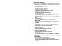
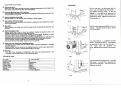
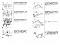
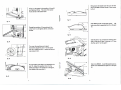
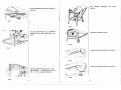
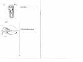
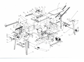
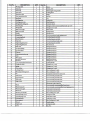
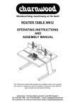
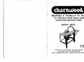
[ddaa\u)oodj
Machinery & Tooling at its best!
12" CONTRACTORS TABLE SAW
OPERATING INSTRUCTIONS
MODEL: W625
Charnwood, 1 Rowan Street, Leicester, L E 3 9GP
Tel. 0116 251 1550 Fax. 0116 253 2891
email; [email protected] website; www.charnwood.net
General Safety Instructions
WARNING!
Read all these instrutions before attempting to operate this to operate this productt and
save these instructions.When using electric tools.basic safety pretty precautions should
always be followed to reduce the risk of fire.electric shock and personel injury, including.
1. Keep work area clear:
Cluttered areas and benches invite injuries.
2.
Consider work area environment:
Do not expose tools to rain or high humidity.
Do not use tools in damp or wet locations.
Keep work area well lit.
Do not use tools in the presence of flammable liquids or gases.
3.
Guard against electric shock:
Avoid body contact with earthed or grounded surfaces.
4.
Keep other persons away.
Do not let persons involved in the work, especially children, touch
extension cord and keep them away from the work area.
the tool or
5.
Store idle tools away:
When not in use, tools should be stored in a dry locked-up place out If reach of
children.
6.
Do not force the tool:
It will do the job better and safer at the rate for which it was intended.7.
7.
Use the right tool:
Do not force small tools to do the job of a heavv-duty tool.
Do not use tools for purposes not intended.for example.do not use circular saws to cut
tree limbs,logs..
8.
Dress properly:
Do not wear loose clothing or jewellery, they can be caught in the moving parts.
Non-skid footwear is recommended when working outdoors.
Wear protective hair covering to contain to contain long hair.
9.
Use protective equipment:
Use safety glasses.
Use face or dust mask if cutting operations create dust.
Use ear protection at all times
10. Connect dust extraction equipment:
If devices are provided for the connection of dust extraction and collecting
equipment.ensure these are connected and properly used.
11. Do not abuse the cord:
Never pull the cord to disconnect it from the socket. Keep the the cord away from
heat,oil and sharp edges.
12. Secure work:
Where possible use clamps or a vice to hold the work it is safer than using your hands.
13. Do not overreach:
14. Keep proper footing and balance at all times:
Keep cutting tools sharp and clean for better and safer performance.
Follow instructions for lubricating and changing accessories.
Inspect tool cords periodically and if damaged have them replaced by an authorized
service center.
2
Keep handles dry and clean .
Assembly
15. Disconnet tools:
When not in use, before serving and when changing accessories such as blades, bits
and cutters, disconnect tools from the power supply.
Put the main part 1 on the proper table for
tools . Use 3 pes M6X16 six-head screw, 1
pes M6X20 six-head screw , 4 pes flat
washer 6 , 4 pes M6 Nut to assemble the
part 2 on the main part 1 .(the screw can't be
tightened too firmly , M6X20 six-head screw
in the position A)
16. Remove adjusting keys and wrenches:
From the habit of checking to see that keys and adjusting wrenches are removed from
the tool before turning in on.
17. Avoid unintentional starting:
Ensure switch is in "off' position when plugging in power supply.
18. Use outdoor extension leads:
When the tool is used outdoors, only extension extension cords intended for outdoor
use and so marked.
fig. 1
19. Stay alert:
Watch what you are doing, use common sense and do not operate the tool when you
are tired.
20. Check damaged parts:
Before furthur use of tool, it should be carefullv checked to determine that it will
operate properly and perform its intended function.
Check for alignment of moving parts, binding of moving parts. Breakage of parts.
Mounting and any other conditions that may affect its operation.
A guard or other part that is damaged should be properly repaired or replaced by an
authorized service center unless otherwise indicated in thie instruction manual.
Center defecive switches replaced by an authorized service center.
Do not use the tool if the switch does not turn it on and off.
Use 2 pes pan head screw M4X60, 2 pes pc
washer, 2 pes M4 Nut to mount the switch
(6 ) on the part 2 .
fig. 2
Use 3 pes M6X16 > 1 pes M6X20 six-head
screw > 4 pes M6 flat washer, 4 pes M6 Nut
to assembly the part 3 on the main part 1.
The screw can't be tightened too
firmly .(M6X20 six-head screw in the position
B)
21. Have your tool repaired by a qualified person:
This electric tool complies with the relevant safety rules and regulations in Australia
and New Zealand.
Repairs should only be carried out by qualified persons, using original spare parts,
othewise this may result in considerable danger to the user.
22. Warning:
The use of any accessoty or attachment other than one recommended in this
instruction manual may present a risk of personal injury.
TECHNICAL DATA
fig. 3
AC motor
Isolation class
Table size
Table height
Cutting depth
Mnotor speed
Voltage
Saw blade
Pi 2.0kwS6 40%
B
800x550mm
850mm
82mm
2950rpm
230V-50Hz
<t>315x*30x3mm
Use 4 pes M6X16 six-head screw , 4 pes M6
flat washer > 4 pes M6 Nut to assemble the
part 4 on the main part 1 . The screw can't be
tightened too firmly.
fig. 4
3
Use 6 pes M6X16 six-head screw, 6 pes M6
flat w a s h e r , 6 pes M6 Nut to assemble the
part 5 , the part 7 , the part 8 on the main part
1 .The screw can't be tightened too firmly.
Assembly the part 15 on the front side of the
main part 1, in the process ,1 pes M6X16
sex head screw, 1 pes M6 washer, 1 pes M6
Nut and 1 pes M6X20 six head screw (in the
position of A)
fig. 5
fig. 9
Use 12 pes M6X16 six-head screw , 12 pes
M6 flat w a s h e r , 12 pes M6 Nut to connect
the part 9, 10 and part 2 , 3 , 4 , 5 T h e screw
can't be tightened too firmly .
Assembly the part 15 on the left side on the
main part 1, in the process , 1 pes M6X16
six head screw, 1 pes M6 washer, 1 pes M6
Nut and 1 pes M6X20 six head screw (in the
position of B)
fig. 6
Use 4 pes M6X16 six-head screw 4 pes M6
flat w a s h e r , 4 pes M6 Nut to connect the
part 11 and part 8 , 9 . The screw can't be
tightened too firmly.
fig. 10
Use 4 pes M4X10 six head screw to
assemble part 14 on the part B
fig. 7
fig. 11
Assembly the part 15 on the front side of the
main part 1 .In the process ,1 pes M6X16
six-head screw , 1 pes M6 washer. 1 pes
Nut and 1 pes M6X20 six-head screw (in
the position of A)
Use 4 pes M6X16 six-head screw, 4 pes M6
Nut, 4 pes flat washer to assemble the part
16 . Assembly on the part 4 and part 5 . The
screw can't be tightened too firmly
fig. 12
5
6
In fig 14 , the screw in the position of A and B
are tightened firmly . The end of the screw
must can be at the same level.
Bring down the blade insert the part 19 then
use 4 pes M6X16 cross counter -sunk screw
to fix it,
fig. 13
Except the position of H according to the
order from A to G tighten all the unmouted
screws.
Use M6X25 cross round-head screw > M6
lock screw Nut to assemble the 20 on the part
18.
Use the part 21 to connect the blowing-wind
hole in the part 20 and in the part 14 .Then
clip the part 21 on the part 7.
fig. 14
Torn over the machine and make it
stand.then adjust the part 17 on the spare
part 16 to make the part 17 reach the ground
use screw to fix it.
fig. 15
Do not loosen screw Nut A and assemble the
part 18 .Adjust the position from it to the
blade according to the measure in the figure,
then tighten the screw Nut A.
fig. 16
7
Use 2 pes M6X20, 2 pes M6 papilionaceous
screw nut to assemble the part 23 on the part
24.
Now finishing
machine.
assembling
the
whole
The machine is easy to move.
Loosen the screw and dismount the part 20.
Loosen the screw and dismount the part 19 .
fig. 24
10
Use specified tool 30 to Loosen the screw
fixing the blade.
Dismount the part 31 and the
32 ,then can change the new blade
11
blade
Item No.
DESCRIPTION
DESCRIPTION
QTY.
Spring washer
68
Plain washer
67
Hexagon nut 1-style
66
Hexagon socket countersunk(flat) head cap screw
65
Eccentric wheel
64
1
Dust Extractor
63
Holding plate tube
1
Scale poiint
62
Holding plate
2
Nut
61
1
Fit bolt
60
2
Hinge
59
1
58
2
. 57
2
56
4
55
1
Item No.
QTY.
1
Dust Extractor
39
1
Table insert
38
Cup square neck bolt w / short neck
91
Pin
37
Hex. Locking nut 1-style
90
Mitre gauge locking knob
36
3
Hex. Locking nut 1 -style
89
1
Locking board
35
2
Hexagon nut 1-style
88
58
Plain washer
34
1
Hexagon nut 1-style
87
1
Spring
33
Hexagon nut 1-style
86
1
Circlips for shaft
32
1
Locking handle
85
Cross recessed pan head screw
31 '
2
Hexagon nut 1-style
84
Rip Fence
30
Hexagon head bolt
83
Mitre gauge
Rip fence extrusion
29
28
Clip case protective cap
Point
26
27
1
Clip case
25
1
Saw blade plate
24
1
Saw blade flange
23
1
Blade bolt
22
1
Supporting plate.rear
21
1
Supporting plate.front
20
1
Chips box
19
1
Motor Bracket
18
1
Connecting block
17
1
Guide Block
16
1
Handle
15
1
Blade cover left
14
1
Blade cover right
13
1
Riving knife
12
1
Pressure plate
11
1
Riving knife sliding seat
10
9
1
8
Saw blade
7
Strut-extension table
6
Extension table
5
Strut short
4
Stand leg
Strut long
3
Working table
1
2
1
Motor
1
Switch, 230v
Blade height setting handle
1
2
Locking knob
2
1
1
58
10
45
1
Hex. Rivet nut
2
Cup head square neck bolt
74
1
Cross recessed pan head screw
73
1
Cup head square neck bolt
72
Cross recessed pan head tapping screw
Cup head square neck bolt
71
70
Hexagon bolt
69
4
2
Hexagon head bolt
77
2
Hexagon head bolt
76
75
2
1
4
Hexagon head bolt
82
4
Hexagon head bolt
81
1
Hexagon head bolt
80
1
Hexagon head bolt
79
Hexagon head bolt
78
1
1
1
45
4
1
4
2
1
Circlips for shaft
107
1
Height scale
53
1
Tensile spring
106
1
Wrench
52
1
Hex. Locking nut 1-style
105
1
Hose support
51
4
Large plain washer
104
2
Pushing handle
50
9
Large plain washer
103
2
Pushing handle seat
49
1
Circlips for shaft
102
2
Pushing handle cover
48
Hex. Locking nut 1-style
101
1
Wooden push handle
47
1
Lock washer external teeth
100
7
Lock washer external teeth
99
1
Wheel frame,right
Wheel axis
46
45
5
Cross recessed countersunk(flat) head tapping screw
98
1
Wheel frame.left
44
4
Cross recessed countersunk(flat) head screw
97
Wheel
43
1
Miter gauge supporing plate
96
11
Cross recessed pan head screw
95
5
Cross recessed pan head screw
94
11
Cross recessed pan head screw
93
2
Cross recessed pan head screw
92
1
Angle Label
41
1
Table scale
40
42
1
12
2
Hex. Nut
108
1
Hook
54