1
SERVICE MANUAL
Large Format Printer
EPSON Stylus Pro 10000/10000CF
®
SEIJ00020
Notice:
n All rights reserved. No part of this manual may be reproduced, stored in a retrieval system, or transmitted in any form or by any means,
electronic, mechanical, photocopying, recording, or otherwise, without the prior written permission of SEIKO EPSON CORPORATION.
n The contents of this manual are subject to change without notice.
n All effort have been made to ensure the accuracy of the contents of this manual. However, should any errors be detected, SEIKO EPSON
would greatly appreciate being informed of them.
n The above not withstanding SEIKO EPSON CORPORATION can assume no responsibility for any errors in this manual or the consequences
thereof.
EPSON is a registered trademark of SEIKO EPSON CORPORATION.
General Notice:
Other product names used herein are for identification purpose only and may be trademarks or registered trademarks of their
respective owners. EPSON disclaims any and all rights in those marks.
Copyright © 2000 SEIKO EPSON CORPORATION. Printed in Japan.
PRECAUTIONS
Precautionary notations throughout the text are categorized relative to 1)Personal injury and 2) damage to equipment.
DANGER
Signals a precaution which, if ignored, could result in serious or fatal personal injury. Great caution should be exercised in
performing procedures preceded by DANGER Headings.
WARNING
Signals a precaution which, if ignored, could result in damage to equipment.
The precautionary measures itemized below should always be observed when performing repair/maintenance procedures.
DANGER
1. ALWAYS DISCONNECT THE PRODUCT FROM THE POWER SOURCE AND PERIPHERAL DEVICES PERFORMING ANY MAINTENANCE
OR REPAIR PROCEDURES.
2. NO WORK SHOULD BE PERFORMED ON THE UNIT BY PERSONS UNFAMILIAR WITH BASIC SAFETY MEASURES AS DICTATED FOR
ALL ELECTRONICS TECHNICIANS IN THEIR LINE OF WORK.
3. WHEN PERFORMING TESTING AS DICTATED WITHIN THIS MANUAL, DO NOT CONNECT THE UNIT TO A POWER SOURCE UNTIL
INSTRUCTED TO DO SO. WHEN THE POWER SUPPLY CABLE MUST BE CONNECTED, USE EXTREME CAUTION IN WORKING ON
POWER SUPPLY AND OTHER ELECTRONIC COMPONENTS.
WARNING
1. REPAIRS ON EPSON PRODUCT SHOULD BE PERFORMED ONLY BY AN EPSON CERTIFIED REPAIR TECHNICIAN.
2. MAKE CERTAIN THAT THE SOURCE VOLTAGES IS THE SAME AS THE RATED VOLTAGE, LISTED ON THE SERIAL NUMBER/RATING
PLATE. IF THE EPSON PRODUCT HAS A PRIMARY AC RATING DIFFERENT FROM AVAILABLE POWER SOURCE, DO NOT CONNECT IT
TO THE POWER SOURCE.
3. ALWAYS VERIFY THAT THE EPSON PRODUCT HAS BEEN DISCONNECTED FROM THE POWER SOURCE BEFORE REMOVING OR
REPLACING PRINTED CIRCUIT BOARDS AND/OR INDIVIDUAL CHIPS.
4. IN ORDER TO PROTECT SENSITIVE MICROPROCESSORS AND CIRCUITRY, USE STATIC DISCHARGE EQUIPMENT, SUCH AS ANTISTATIC WRIST STRAPS, WHEN ACCESSING INTERNAL COMPONENTS.
5. REPLACE MALFUNCTIONING COMPONENTS ONLY WITH THOSE COMPONENTS BY THE MANUFACTURE; INTRODUCTION OF
SECOND-SOURCE ICs OR OTHER NON-APPROVED COMPONENTS MAY DAMAGE THE PRODUCT AND VOID ANY APPLICABLE EPSON
WARRANTY.
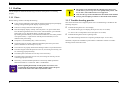
Safety Information
To prevent accidents during a maintenance procedure, strictly observe the Warnings and Cautions. Do not do anything that is dangerous or not within
the scope of this document.
Do not do anything that is dangerous even if not specifically described in this manual. In addition to the descriptions below and those given in this
manual, there are many situations and circumstances that are dangerous. Be aware of these when you are working with the printer.
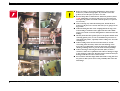
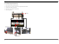
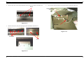
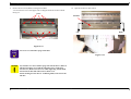
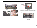
Laser Beam
W A R N IN G
The laser beam used for Auto Point Head
Optimization System is a very powerful, straight,
narrow beam of light that produces extreme heat at
its focal point. Direct eye exposure to the laser beam
may cause eye injury or blindness. Never place a
mirror or a reflective tool or object in the laser beam
path.
To avoid permanent eye damage, follow these directions;
n Before starting any service procedure, switch off the printer
power and unplug the power cord from the wall outlet.
n Do not disassemble the Flushing Duct or any laser component
that displays Laser Warning Sticker.
n Use caution when you are working around the Flushing Duct or
when you are performing laser related repair procedures.
n Do not disassemble the printer in such a way that the laser
beam can exit the printer engine during a print cycle.
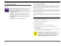
About This Manual
This manual describes basic functions, theory of electrical and mechanical
operations, maintenance and repair procedures of EPSON EPSON Acu Laser
C2000. The instructions and procedures included herein are intended for the
experienced repair technicians, and attention should be given to the precautions
on the preceding page.
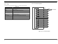
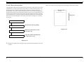
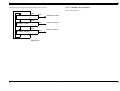
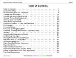
Contents
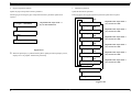
This manual consists of six chapters and Appendix.
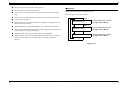
CHAPTER 1. PRODUCT DESCRIPTIONS
Provides a general overview and specifications of the product.
CHAPTER 6. MAINTENANCE
Provides preventive maintenance procedures and the
lists of Epson-approved lubricants and adhesives
required for servicing the product.
CHAPTER 7. APPENDIX
Provides the following additional information for reference:
n Connector pin assignments
n Parts list
n Electric circuit boards components layout
n Exploded diagram
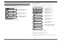
CHAPTER 2. OPERATING PRINCIPLES
Describes the theory of electrical and mechanical operations of the
product.
CHAPTER 3. TROUBLESHOOTING
Provides the step-by-step procedures for the troubleshooting.
CHAPTER 4. DISASSEMBLY AND ASSEMBLY
Describes the step-by-step procedures for disassembling and
assembling the product.
CHAPTER 5. ADJUSTMENTS
Provides Epson-approved methods for adjustment.
n Electrical circuit boards schematics
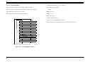
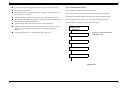
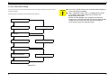
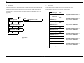
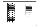
Symbols Used in This Manual
Various symbols are used throughout this manual either to provide additional information on a specific topic or to warn of possible danger present during a
procedure or an action. Be aware of all symbols when they are used, and always read WARNING, CAUTION or NOTE messages.
W A R N IN G
Indicates an operating or maintenance procedure,
practice or condition that, if not strictly observed, could
result in injury or loss of life.
C A U T IO N
Indicates an operating or maintenance procedure,
practice, or condition that, if not strictly observed,
could result in damage to, or destruction of,
equipment.
C H E C K
P O IN T
May indicate an operating or maintenance procedure,
practice or condition that is necessary to accomplish
a task efficiently. It may also provide additional
information that is related to a specific subject, or
comment on the results achieved through a previous
action.
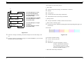
Indicates a reassembly procedure, practice, or
condition that, if not strictly adhered to, could result
in damage to, or non operability of, the equipment.
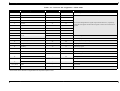
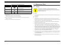
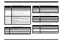
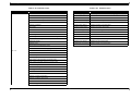
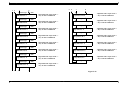
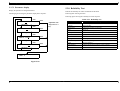
Revision Status
Revision
Issued Date
Rev.A
March 30,2001
Description
First Release
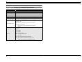
Rev.B
May 1,2001
Chapter 1
• 1.1:Throughput of semiglossy photo paper revised.
• 1.1:”PS server” deleted. Tables of exclusive paper deleted.
• 1.1.1: Ink cartridge code corrected. Specification paper description revised.
• 1.2: Nozzle number for color revised. Paper feed speed added.
• Table 1-6: “Scrim Vinyl” deleted.
• 1.2.5: Discription of paper set lever revised.
• 1.2.7: The power consumption revised.
• 1.2.8: The safety approvals revised.
• 1.2.9: The reliability revised.
• 1.2.10: The cutting specification revised.
• 1.2.13: The physical dimensions revised. The drawing of dimensions unit 2 deleted.
• 1.5.1: The panel display priority revised.
• 1.6.1: Printer Setting Menu revised.
• 1.6.6: Gap adjustment revised.
• 1.7 Maintenance mode revised.
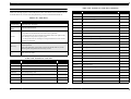
Chapter 2 : Section name revised.
Table 2-2 : The description revised.
2.2.2: The description of shutter and shutter motor added.
Chapter 3
• Table 3-21: Error code for CPU address errors revised.
• P.97,98: Service call error descriptions revised.
• Warning tables added.
Chapter 4
• 4.1.1 : The transportation mode in the checkpoint deleted.
• 4.2.1.1, 4.2.1.2, 4.2.1.5,4.2.1.6,4.2.1.11, 4.2.3.2 : The description of disassembly / assembly
procedure revised.
Chapter 5
• Table 5-2, 5-9 revised.
• Renamed form Banding adjustment to Paper feeding adjustment.
• Offset adjustment revised.
• A13/A123/B123 Slant Adjustment revised.
• Head RL Adjustment renamed from Head Gap Adjustment and revise the table.
• Print head cleaning rename from Print head washing
• P_Front/P_Rear/P_Edge sensor adjustment revised.
1.1 Features ............................................................................................................. 14
1.1.1 Consumable Products & Options ............................................................... 15
1.2 Specifications ..................................................................................................... 16
1.2.1 Print Specifications .................................................................................... 16
1.2.2 Character Specifications ............................................................................ 16
1.2.3 Paper Feed ................................................................................................. 16
1.2.4 Paper .......................................................................................................... 16
1.2.4.1 Roll Paper .......................................................................................... 16
1.2.4.2 Sheet .................................................................................................. 17
1.2.4.3 Printable area ..................................................................................... 21
1.2.5 Paper set lever ............................................................................................ 22
1.2.6 Ink Cartridge .............................................................................................. 22
1.2.7 Electrical specification ............................................................................... 24
1.2.8 Safety approvals ......................................................................................... 24
1.2.9 Reliability .................................................................................................. 25
1.2.10 Environmental Conditions ....................................................................... 25
1.2.10.1 Temperature/Humidity .................................................................... 25
1.2.10.2 Vibration & Shock ........................................................................... 26
1.2.11 Controller ................................................................................................. 26
1.2.12 Cutting Specification ............................................................................... 27
1.2.12.1 Automatic cut of roll media ............................................................. 27
1.2.12.2 Manual cut of roll paper .................................................................. 27
1.2.13 Physical Specification .............................................................................. 28
1.3 Interfaces ...........................................................................................................
1.3.1 Parallel Interface ........................................................................................
1.3.2 USB ............................................................................................................
1.3.3 TYPE-B Optional Interface .......................................................................
1.3.4 Complement Item ......................................................................................
29
29
35
36
36
1.4 Operating Panel ................................................................................................ 38
1.4.1 Indicator Status in Normal Mode .............................................................. 40
1.5 Operating Panel Messages ............................................................................... 41
1.6 SelecType Settings ............................................................................................
1.6.1 Printer Setting Menu ..................................................................................
1.6.2 Test Print Menu .........................................................................................
1.6.2.1 Nozzle check .....................................................................................
1.6.2.2 Status sheet ........................................................................................
1.6.3 Printer Status Menu ...................................................................................
1.6.4 User Paper Setup Menu Items ...................................................................
1.6.4.1 Detecting Paper Thickness ................................................................
42
44
45
45
45
46
47
47
1.6.5 Cutter Replacement Menu ......................................................................... 48
1.6.6 Gap Adjustment ......................................................................................... 49
1.7 Maintenance Mode ...........................................................................................
1.7.1 Outline .......................................................................................................
1.7.2 Hexadecimal Dump ...................................................................................
1.7.3 Panel Display Language Select .................................................................
1.7.4 Auto nozzle check .....................................................................................
1.7.5 Ink information menu ................................................................................
50
50
53
53
53
53
1.8 Maintenance Mode 2 ........................................................................................ 54
1.9 Jumper Settings ................................................................................................ 58
2.1 Description ........................................................................................................ 61
2.2 Printer Mechanism Components ....................................................................
2.2.1 Carriage device section ..............................................................................
2.2.2 Paper feed section ......................................................................................
2.2.3 Cleaning device section .............................................................................
2.2.4 Dot missing detector / Flushing box ..........................................................
2.2.5 Ink pump Assy ...........................................................................................
2.2.6 Ink supply device section ..........................................................................
2.2.7 Others .........................................................................................................
63
67
73
77
79
80
81
82
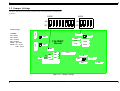
2.3 C362MAIN board ............................................................................................. 83
2.4 C362DRV board description ........................................................................... 84
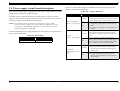
2.5 Power supply circuit board description ......................................................... 85
3.1 Outline ............................................................................................................... 87
3.1.1 First... ......................................................................................................... 87
3.1.2 Trouble-shooting practice .......................................................................... 87
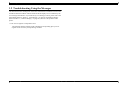
3.2 Troubleshooting Using the Messages .............................................................. 88
3.2.1 Warnings .................................................................................................... 93
3.2.2 Errors ......................................................................................................... 94
3.3 Service engineer require message ................................................................. 101
3.3.1 Maintenance call ...................................................................................... 101
3.3.2 Fatal error ................................................................................................ 102
3.4 Troubleshooting Based On Printout .............................................................
3.4.1 Dot Missing .............................................................................................
3.4.2 Uneven Printing / Poor Resolution ..........................................................
3.4.3 Smudged or Marred Printout (Front) .......................................................
3.4.4 Smudged or Marred Printout (Reverse side) ...........................................
3.4.5 White or Black Banding ..........................................................................
111
111
111
112
112
112
4.1 Summary ......................................................................................................... 114
4.1.1 Warnings .................................................................................................. 114
4.1.2 Tools ........................................................................................................ 118
4.1.3 Screw List ................................................................................................ 118
4.2 Disassembly Flow ............................................................................................ 119
4.2.1 Removing the Housing ............................................................................ 120
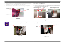
4.2.1.1 Panel Unit Removal ......................................................................... 120
4.2.1.2 Paper Set Lever Removal ................................................................ 122
4.2.1.3 H Top Cover Removal .................................................................... 123
4.2.1.4 R Side Cover Removal .................................................................... 124
4.2.1.5 L Side Cover Removal .................................................................... 124
4.2.1.6 I/C Holder Cover Removal .............................................................. 125
4.2.1.7 Rear Cover Removal ....................................................................... 126
4.2.1.8 Paper Guide L Removal .................................................................. 128
4.2.1.9 Roll Paper Cover Removal .............................................................. 130
4.2.1.10 Front Cover Removal .................................................................... 130
4.2.1.11 Removing Paper Guide U .............................................................. 131
4.2.2 Circuit Board Removal ............................................................................ 133
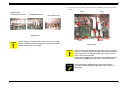
4.2.2.1 Power Board Removal ..................................................................... 133
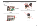
4.2.2.2 HJFK / Dummy Board Removal ..................................................... 134
4.2.2.3 C362MAIN Board Removal ........................................................... 135
4.2.2.4 CSIC Board Removal. ..................................................................... 137
4.2.2.5 C362DRV Board Removal .............................................................. 138
4.2.2.6 P/S Fan Removal ............................................................................. 141
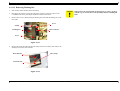
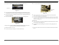
4.2.3 Printer Mechanism Disassembly ............................................................. 142
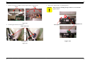
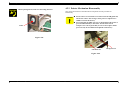
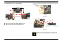
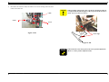
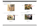
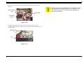
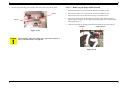
4.2.3.1 Replacing the Waste Ink Unit ......................................................... 143
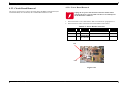
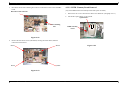
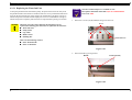
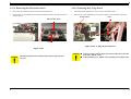
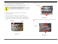
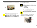
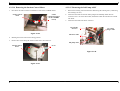
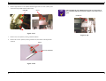
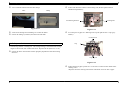
4.2.3.2 Removing the Suction Fans ............................................................. 146
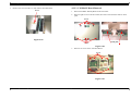
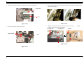
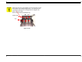
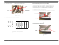
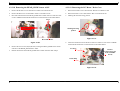
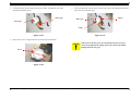
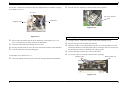
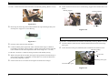
4.2.3.3 Replacing the Printheads ................................................................. 151
4.2.3.4 Removing the Cutter and Cutter unit .............................................. 158
4.2.3.5 Removing the CR Encoder Sensor .................................................. 160
4.2.3.6 Removing the P_Edge Sensor ......................................................... 160
4.2.3.7 Removing the Ink Cartridge Holder & Slots ................................... 161
4.2.3.8 Removing the CR Motor / Pulley ASSY ......................................... 163
4.2.3.9 Removing the PF Motor ASSY ....................................................... 164
4.2.3.10 Removing the PF Encoder ............................................................. 166
4.2.3.11 Removing the Cleaning Unit ......................................................... 167
4.2.3.12 Removing Flushing Box ................................................................ 170
4.2.3.13 Removing Dot Missing Detector ................................................... 171
4.2.3.14 Removing the Suction Control Motor ........................................... 173
4.2.3.15 Removing the Ink Pump ASSY ..................................................... 173
4.2.3.16 Removing the T Fence (Scale 180a) .............................................
4.2.3.17 Removing the Paper Hold Solenoid .............................................
4.2.3.18 Removing the HEAD_SLIDE Sensor ASSY ................................
4.2.3.19 Removing the PG Motor / Drive Gear ..........................................
4.2.3.20 Removing the CR_HP Sensor .......................................................
4.2.3.21 Removing the Paper Release Sensor .............................................
4.2.3.22 Removing the P_FRONT Sensor ASSY .......................................
4.2.3.23 Removing the P_REAR Sensor ASSY .........................................
4.2.3.24 Removing the Front Cover Sensor ASSY .....................................
4.2.3.25 Removing the I/C Holder Cover Sensor ASSY ............................
4.2.3.26 Removing the P_THICK Sensor ...................................................
174
175
177
177
179
181
181
183
183
184
185
5.1 Adjustment Outline ........................................................................................
5.1.1 Precautions ...............................................................................................
5.1.2 Adjustment Tools ....................................................................................
5.1.3 Adjustment Items .....................................................................................
188
188
188
190
5.2 Adjustment Steps ............................................................................................
5.2.1 Parameter Backup ....................................................................................
5.2.2 Firmware Upload .....................................................................................
5.2.3 Mechanism Adjustment ...........................................................................
5.2.3.1 CR steal belt tension adjustment .....................................................
5.2.3.2 PF timing belt tension adjustment ...................................................
5.2.3.3 P_THICK sensor fixing bracket adjustment ...................................
5.2.3.4 Cutter position adjustment ..............................................................
5.2.3.5 Front cover sensor adjustment .........................................................
5.2.3.6 Slide idler gear / Slide motor fixing plate adjustment .....................
5.2.3.7 T fence and CR encoder position adjustment ..................................
5.2.3.8 Head slant adjustment .....................................................................
5.2.3.9 Offset adjustment for dot missing detector .....................................
5.2.3.10 P_Front/Rear/Edge sensor adjustment ..........................................
5.2.3.11 Paper feeding adjustment ..............................................................
5.2.3.12 Cutter Pressure Adjustment ...........................................................
5.2.4 Program, User data install .......................................................................
5.2.5 USB-ID backup .......................................................................................
191
191
193
194
195
197
197
198
199
199
200
200
201
201
203
206
207
207
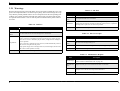
5.3 Self-Diagnostics ...............................................................................................
5.3.1 Start-up procedure ...................................................................................
5.3.2 Button operation during the Self-Diagnostics .........................................
5.3.2.1 Top menu .........................................................................................
5.3.3 Test ..........................................................................................................
5.3.3.1 Test menu sequence ........................................................................
208
213
214
214
215
215
5.3.3.2 Version display ................................................................................ 216
5.3.3.3 Panel ................................................................................................ 217
5.3.3.4 Sensor .............................................................................................. 217
5.3.3.5 Encoder ............................................................................................ 218
5.3.3.6 Fan ................................................................................................... 219
5.3.3.7 Encode ............................................................................................. 219
5.3.3.8 D/A correction ................................................................................. 221
5.3.3.9 Head signal shape ............................................................................ 224
5.3.3.10 CSIC information display .............................................................. 224
5.3.3.11 Actuator ......................................................................................... 225
5.3.4 Adjustment ............................................................................................... 227
5.3.4.1 Adjustment menu ............................................................................ 228
5.3.4.2 Paper Skew ...................................................................................... 228
5.3.4.3 Head Rank input .............................................................................. 229
5.3.4.4 Head nozzle check ........................................................................... 235
5.3.4.5 Offset Adjustment ........................................................................... 237
5.3.4.6 Test report for dot missing detector ................................................ 238
5.3.4.7 A13 slant adjustment ....................................................................... 239
5.3.4.8 A123 slant adjustment ..................................................................... 240
5.3.4.9 B123 slant adjustment ..................................................................... 241
5.3.4.10 Bi-D adjustment ............................................................................ 242
5.3.4.11 Head LR (Head gap) adjustment ................................................... 244
5.3.4.12 Feed adjustment ............................................................................. 246
5.3.4.13 Top and Bottom adjustment .......................................................... 247
5.3.4.14 Rear sensor position ...................................................................... 248
5.3.4.15 Test pattern print ........................................................................... 249
5.3.4.16 Print head cleaning ........................................................................ 250
5.3.4.17 Counter clear ................................................................................. 251
5.3.5 Cleaning ................................................................................................... 252
5.3.5.1 Normal cleaning KK0 ..................................................................... 252
5.3.5.2 Normal cleaning KK1 ..................................................................... 252
5.3.5.3 Normal cleaning KK2 ..................................................................... 252
5.3.5.4 Initial ink charge .............................................................................. 252
5.3.6 Print .......................................................................................................... 253
5.3.6.1 Check pattern ................................................................................... 254
5.3.6.2 ......................................................................................................... 254
5.3.7 Parameter ................................................................................................. 254
5.3.7.1 Initialize the parameter .................................................................... 255
5.3.7.2 Update parameter ............................................................................ 259
5.3.7.3 Parameter display ............................................................................ 264
5.3.8 Reliability Test ........................................................................................
5.3.8.1 CR Motor .........................................................................................
5.3.8.2 PF Motor .........................................................................................
5.3.8.3 CR + PF Motor ................................................................................
5.3.8.4 Cutter ...............................................................................................
5.3.8.5 Head Up / Down ..............................................................................
5.3.8.6 Head lock .........................................................................................
5.3.8.7 Lever lock ........................................................................................
5.3.8.8 Cleaning ..........................................................................................
5.3.8.9 Print .................................................................................................
5.3.8.10 Shutter ...........................................................................................
5.3.8.11 Total reliability ..............................................................................
5.3.8.12 Life confirmation ...........................................................................
264
266
267
268
269
270
271
271
272
273
273
274
275
6.1 General Maintenance Issues ..........................................................................
6.1.1 Periodic Maintenance Items ....................................................................
6.1.2 Product Life Information .........................................................................
6.1.3 Printing output at the time of maintenance ..............................................
277
278
278
279
6.2 Maintenance inspection items ...................................................................... 282
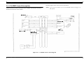
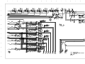
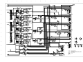
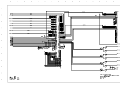
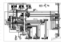
7.1 Wiring Diagrams ............................................................................................ 290
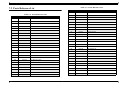
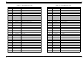
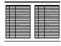
7.2 Parts Reference List ....................................................................................... 292
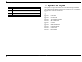
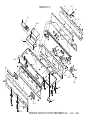
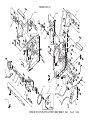
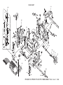
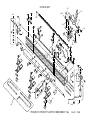
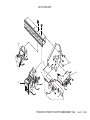
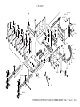
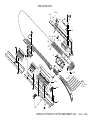
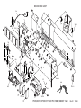
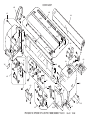
7.3 Exploded View Diagram ................................................................................ 296
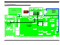
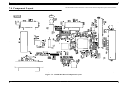
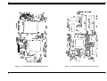
7.4 Component Layout ......................................................................................... 308
7.5 Circuit Diagram .............................................................................................. 313
CHAPTER
PRODUCT DESCRIPTION
EPSON Stylus Pro 10000/10000CF
Revision B
o The latest RIP technology
1.1 Features
n CPSI Pro
software RIP
The EPSON Stylus Pro 10000/10000CF is the ultra high picture quality B0+ size supported
large size full collar ink jet printer that applied Epson original photograph mach jet
technology. The EPSON Stylus Pro 10000/10000CF provides the following major features
and more.
o Large Format
Max. 44” paper width, B0+ size supported
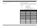
o High-speed throughput
There is not case print speed relys on the performance of the host computer
largely, to be equipped with standard the HJFK board.
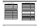
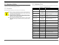
Table 1-1. Throughput Speed
EPSON media
Plain Paper
Quality
Resolution
Mode
Throughput
(A0 printing time)
Speed
360x360dpi
Bi-D MF, 240cps
4 min.
Speed
720x360dpi
Bi-D FOL, 300cps
6 min.
720x720dpi
Bi-D FOL, 300cps
10 min.
1440x720dpi
Bi-D 4Pass, 300cps
19 min.
Semigloss Photo
Quality
Paper
Adv. Photo
o High quality
High image quality with 6-color ink, 1440X720dpi, and minimum 5pl various
layers.
High image quality and color reproduction same level as Stylus Photo 1200/ Stylus
Color 5500.
o Low running cost
Independent for each color and large capacity 500ml ink cartridge.
o Various Paper Handling
Support various media. All media is compatible with Stylus Pro 9000 and Stylus
Pro9500.
Double roll paper holders
Automatic roll paper cutter, manual cutter
Automatic loading (cut sheet)
o Compatibility with Stylus Pro 9000/ Stylus Pro 7000/ Stylus Pro 7500
Commands are upper compatible with Stylus Pro 9000 / Stylus Pro 9500 / Stylus
Pro 7000 / Stylus Pro 7500
Product Description
Features
14
EPSON Stylus Pro 10000/10000CF
Revision B
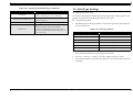
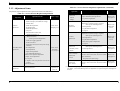
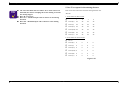
1.1.1 Consumable Products & Options
Table 1-2. Consumable products & Options (continued)
Name
Table 1-2. Consumable products & Options
Product
Rip Station 5100 PS
Server Series II
Name
Code
Black Ink
Cyan Ink
Magenta Ink
Yellow Ink
Light Cyan Ink
Light Magenta Ink
Software RIP (CPSI Pro)
Ink cartridges for Stylus
Pro 10000
T499011
T502011
T501011
T500011
T504011
T503011
Ink cartridges for Stylus
Pro 10000CF
T511011
T512011
T513011
T512011
T516011
T515011
Black Ink
Cyan Ink
Magenta Ink
Yellow Ink
Light Cyan Ink
Light Magenta Ink
Stand
C844022
Optional stand
Paper cutter blade
C815131
Consumable item
Roll Feed Spindle 2”
C811092
For two-inch diameter roll paper
Roll Feed Spindle 3”
C811102
For three-inch diameter roll paper
Glossy Photo Paper
S041225
610mm (24 in.) wide/20.7m long
Semigloss Photo Roll
Paper
S041223
24 in wide/25m long
Presentation Matte Roll
Paper
S041220
24 in wide/25m long
S041079
S041068/S041045
S041069/S041043
S041070/S041044
A2
A3
A3 Wide/B
B
Photo Paper
S041142
S041143
S041156
A3
A3 Wide/B
B
Photo Quality Glossy
Film
S041073
S041074
S041075
A3
A3 Wide/B
B
Photo Quality Ink Jet
Paper
Product Description
Code
EAI - C850092
Other - C850093
Product
Fiery Adobe® PostScript® 3™ Server
Software RIP (CPSI Pro)
Multi-protocol Ethernet
interface card
C82362¬
Type-B 10Base-T
100Mbps Multi-protocol
Ethernet interface card
C82363¬
Type-B 100Base-T
IEEE 1394 interface
card
C82372¬
IEEE 1394 interface card
Note: Signifies a number that varies by market.
Features
15
EPSON Stylus Pro 10000/10000CF
Revision B
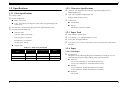
1.2 Specifications
1.2.2 Character Specifications
o Character code: English several character expansion graphics(PC437)
Multilingual(PC850)
1.2.1 Print Specifications
o Type style: an EPSON original type style
o Printing : Inkjet
o Nozzle configuration
English several character Courier
o Control code:
n Black - 180 nozzles
n
n Color - 900 nozzles (cyan, magenta, yellow, light cyan, light magenta, 180
nozzles each)
ESC/P Raster
n ESC/P3
o Print direction : Bi-direction (high-speed return, high-speed skip only)
Not mention to the users’ manual.
o Print Speed and Printable Area
1.2.3 Paper Feed
n Character mode
Character quality : high quality
o Paper feeding : Friction feed
Character pitch : 10cpi (Pica)
o
Line spacing : 1/6" or programmable at 1/720"
Printable area : 437 characters
o
Paper path : Roll paper/manual
Printing speed : 240 cps
o
Feed speed : 215+/-10ms (6.35mm paper feed, except front rush, back rush &
hold time )
n Graphic mode
Table 1-3. Print Area and Speed
1.2.4 Paper
Horizontal resolution
(dpi)
Printable area
Max. printable dots
360
43.78 inch
15762
24IPS/FOL
720
43.78 inch
31524
30IPS/FOL
1440
43.78 inch
63048
30IPS/4pass
Speed
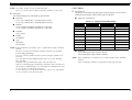
1.2.4.1 Roll Paper
o Specifications
The printer accepts following plain paper and EPSON special paper. It is not
assured feeding and print quality with any other paper except them.
n Paper Size
2"core: 210~1118mm (W) x ~45m (H) (within roll size)
3"core: 210~1118mm (W) x ~202m (H) (within roll size)
n Roll Size
2"core: 103mm ext. diameter maximum for 2 roll setting
3"core: 150mm ext. diameter maximum for 1 roll setting
n Thickness
0.08~0.5mm
Product Description
Specifications
16
EPSON Stylus Pro 10000/10000CF
Revision B
1.2.4.2 Sheet
NOTE: No wrinkle, no fuzz, no tear, no fold with paper
If 3" core is used, exclusive option (roll paper spindle 3") is necessary
o Specifications
It is assured feeding only with following specifications.
The printer accepts following plain paper and special paper. It is not assured
feeding and print quality with any other paper except them.
n Paper Size
n Paper Size : Following list
o Plain paper
2"core: 210~1118mm (W) x ~45m (H) (within roll size)
3"core: 210~1118mm (W) x ~202m (H) (within roll size)
Table 1-4. Supported Cut-Sheet Paper
Paper Size
n Roll Size
2"core: 103mm ext. diameter maximum for 2 roll setting
3"core: 150mm ext. diameter maximum for 1 roll setting
n Thickness
0.08~0.11mm
n Weight
64~90gf/m2
n Type
Plain paper
Recycle paper
NOTE: Paper should have no wrinkles, tears, or folds and the surface should be
smooth.
The force to remove the end of the roll paper from the core should be
between 300gf and 2000gf
If 3" core is used, a product-exclusive option (roll paper spindle 3") is
necessary.
It is used under normal condition (temperature 15°C~25°C, humidity
40%~60%RH)
Roll paper can be printed before paper come out of the core.
Reference: Remaining paper length when roll paper come out of the core
40 cm approx. (TBD) for upper core, 30 cm approx. (TBD) for lower core
2" core can be set 2 rolls at the same time.
3" core cannot be set 2 rolls at the same time. (One 2" core roll and one
3" core roll can be set at the same time.)
Product Description
Size (H x W)
Paper Size
Size (H x W)
1118 x 1580mm
A2
420mm x 594mm
B0
1030 x 1456mm
A3+
329mm x 483mm
B1
728 x 1030m
A3
297mm x 420mm
B2
515mm x 728mm
A4
210 x 297mm
B3
364 x 515mm
US E
34 x 44"
A0+
914 x 1292mm
US D
22 x 34"
A0
841 x 1189mm
US C
17 x 22"
A1+
24 x 36"
US B
11 x 17"
A1
594mm x 841mm
Letter
8.5" x 11inch
n Thickness
0.08~1.5mm (paper length; 279mm~728mm)
0.08~0.5mm (paper length; 728mm~1580mm)
NOTE: Paper should have no wrinkles, tears, or folds and the surface should be
smooth.
0.08~1.5mm paper thickness is supported for long-edge insertion.
Specifications
17
EPSON Stylus Pro 10000/10000CF
Revision B
o Plain paper
It is assured feeding only with following specifications.
n Paper Size : Following list
Table 1-5. Supported Cut-Sheet Paper
Paper Size
Size (H x W)
Paper Size
Size (H x W)
1118 x 1580mm
A2
420mm x 594mm
B0
1030 x 1456mm
A3+
329mm x 483mm
B1
728 x 1030m
A3
297mm x 420mm
B2
515mm x 728mm
A4
210 x 297mm
B3
364 x 515mm
US E
34 x 44"
A0+
914 x 1292mm
US D
22 x 34"
A0
841 x 1189mm
US C
17 x 22"
A1+
24 x 36"
US B
11 x 17"
A1
594mm x 841mm
Letter
8.5" x 11inch
n Thickness
0.08~0.11mm
n Weight
64~90gf/m2
n Type
Plain paper
Recycle paper
NOTE: Paper is fed short-edge first.
Paper should have no wrinkles, tears, or folds and the surface should be
smooth.
It is used under normal condition (temperature 15°C~25°C, humidity
40%~60%RH)
Product Description
Specifications
18
EPSON Stylus Pro 10000/10000CF
Revision B
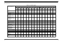
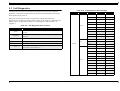
o Special paper
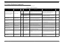
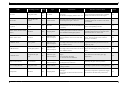
Table 1-6. Exclusive paper
Media Size
Supporting Media List
Sheet
Roll Paper
A4
LTR
A3
B
Super
A3/B
A2
C
B2
B1
210m
m
329m
m
22"
24"
36"
44"
210x2
97
216x2
76
297x4
20
279x4
32
329x4
83
420x5
94
432x5
59
515x7
28
728x1
030
210
329
560
610
914
1118
Photo Quality Ink Jet
Paper
@
@
@
@
@
@
@
-
-
-
-
-
-
-
-
Photo Quality Glossy Film
@
@
@
@
@
-
-
-
-
-
-
-
-
-
-
<<Dye >>
Photo Paper
@
@
@
@
@
-
-
-
-
#
#
-
-
-
-
Glossy Photo Paper
(except US)
Glossy Paper - Heavy
Weight (US)
-
-
-
-
-
-
-
-
-
-
-
-
O
O
O
Semigloss Photo Pape
(except US)r
Semigloss Paper - Heavy
Weight (US)
-
-
-
-
-
-
-
-
-
-
-
-
O
O
O
Presentation Matte Paper
-
-
-
-
-
-
-
-
-
-
-
-
O
O
O
Glossy Film
-
-
-
-
-
-
-
-
-
-
-
-
O
O
O
Heavyweight Polyester
Banner
-
-
-
-
-
-
-
-
-
-
-
-
O
O
O
Poster Board-Semigloss
-
-
-
-
-
-
-
O
O
-
-
-
-
-
-
DuPont/EPSON
Commercial Proofing
Paper
-
-
-
-
-
-
-
-
-
-
-
-
O
O
-
DuPont/EPSON
Commercial Matte
Proofing Paper
-
-
-
-
-
-
-
-
-
-
-
-
O
O
-
DuPont/EPSON
Publication Proofing Paper
-
-
-
-
-
-
-
-
-
-
-
-
O
O
-
Doubleweight Matte Paper
-
-
-
-
-
-
-
-
-
-
-
-
O
O
O
Glossy Paper-Photo
Weight
@
@
-
-
@
-
-
-
-
-
-
O
-
-
O
Glossy Film
-
-
-
-
-
-
-
-
-
-
-
-
O
O
O
Premium Glossy Photo
Paper
-
-
-
-
-
-
-
-
-
-
-
-
O
O
O
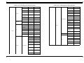
<<Pigment >>
Product Description
Specifications
19
EPSON Stylus Pro 10000/10000CF
Revision B
Table 1-6. Exclusive paper
Premium Semigloss Photo
Paper
-
-
-
-
-
-
-
O
O
-
-
-
O
O
O
Photo Grade Glossy
Paper(except US)
Photo Glossy Paper (US)
-
-
-
-
-
-
-
-
-
-
-
-
O
O
O
Photo Grade Semigloss
Paper (except US)
Photo Semigloss Paper
(US)
-
-
-
-
-
-
-
-
-
-
-
-
O
O
O
Premium Luster Photo
Paper
-
-
-
-
-
-
-
-
-
-
-
-
O
O
O
Watercolor Paper-Radiant
White
-
-
-
-
O
-
-
-
-
-
-
-
O
O
O
Smooth Fine Art Paper
(Roll paper)
-
-
-
-
-
-
-
-
-
-
-
-
O
O
O
Smooth Fine Art Paper
(Sheet)
-
-
-
-
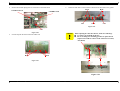
-
-
-
24"x30"
36"x44"
O
O
-
-
-
-
-
-
Textured Fine Art Paper
(Roll paper)
-
-
-
-
-
-
-
-
-
-
-
-
O
O
O
Textured Fine Art Paper
(Sheet)
-
-
-
-
-
-
-
24"x30"
36"x44"
O
O
-
-
-
-
-
-
Backlight film
-
-
-
-
-
-
-
-
-
-
-
-
O
O
O
Heavyweight Polyester
Banner
-
-
-
-
-
-
-
-
-
-
-
-
O
O
O
Synthetic Paper
-
-
-
-
-
-
-
-
-
-
-
-
O
O
O
Adhesive Synthetic Paper
-
-
-
-
-
-
-
-
-
-
-
-
O
O
O
Tyvek
-
-
-
-
-
-
-
-
-
-
-
-
O
O
O
Adhesive Vinyl
-
-
-
-
-
-
-
-
-
-
-
-
O
O
O
DuPont/EPSON
Semigloss Proofing
Paper-A
-
-
-
-
-
-
-
-
-
-
-
O
-
-
O
O assured
# added media (Media venders support basically.)
@ assured only for paper feeding
Product Description
Specifications
20
EPSON Stylus Pro 10000/10000CF
Revision B
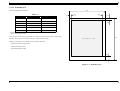
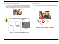
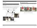
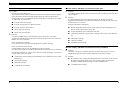
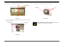
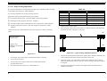
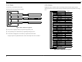
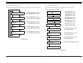
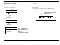
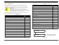
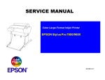
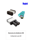
1.2.4.3 Printable area
PW
The list and figure shown below.
Table 1-7.
LM
Heading
Roll Paper
Cut Sheets
PW (width)
210 ~1118mm
210 ~ 1118mm
PL (length)
Max. 202mm
279~1580mm
LM (left margin)
3mm/15mm*1
3mm
RM(Rightlmargin)
3mm/15mm*1
3mm
TM (top margin)
3mm/15mm*1
3mm
BM (bottom)
3mm/15mm*1
14mm
RM
TM
-The printer detects paper width when paper is set. (If Set paper width detection is OFF, it
doesn’t detect paper width.)
-It doesn’t print the image beyond printable area specified with paper size setting or paper width
PL
Printable area
detection. (It may print on the platen if Set paper width detection is OFF.)
-Margins of roll paper can be changed with the panel as following;
Top/bottom 15mm, left/right 3mm
Top/bottom/left/right 3mm
Top/bottom/left/right 15mm
BM
Figure 1-1. Printable Area
Product Description
Specifications
21
EPSON Stylus Pro 10000/10000CF
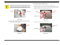
1.2.5 Paper set lever
n
When the paper set lever is pulled to the front, paper is released.
n When the paper set lever is pushed down to the back, paper is fixed, and it
becomes print ready.
n
Revision B
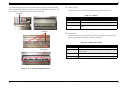
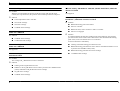
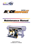
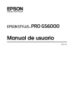
1.2.6 Ink Cartridge
o Pigment / Dye ink cartridge
Type
:
Exclusive ink cartridge
Dimension
:
168mm (W) x 344mm (D) x 30.3mm (H)
The paper set lever cannot be released during printing operation.
*33.3mm (H) including guide ribs
Ink capacity :
500ml
Total weight :
860g (without case, ink weight 535Å}25g)
Effective ink :
more than 485g
Color
Black, magenta, light magenta, cyan, light cyan, yellow
:
Environment condition :
10°C~40°C (temperature), 5%~85% (humidity)
no dew condensation
Storage temperature :
packed: -30°C~40°C (within 1 month when 40°C)
unpacked: -20°C~40°C (within 1 month when 40°C, within 120 hours when 60°C)
Ink life :
pigment:
2 years from production date / 6 months after open
dye:
2 years from production date / 2 years after open
.
Table 1-8. Ink Cartridge Specifications
Product Description
Situation
Temperature
Transporting
-30~60°C
• Less than a month at 40°C
• Less than 120 hours at 60°C
Storage
-30~40°C
Less than a month at 40°C
Installed
-20~40°C
Less than a month at 40°C
Specifications
Notes
22
EPSON Stylus Pro 10000/10000CF
Revision B
Figure 1-2. Ink Cartridge Physical Specifications 500ml
Product Description
Specifications
23
EPSON Stylus Pro 10000/10000CF
Revision B
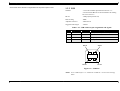
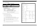
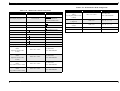
1.2.7 Electrical specification
1.2.8 Safety approvals
Rated voltage : AC 100 ~ 240V
o 120Vversion
Input voltage range : AC 90 ~ 264V
n Safety standard
: UL1950
Rated frequency range : 50 ~ 60Hz
: CSA22.2 No.950
Input frequency range : 49 ~ 61Hz
Rated current : 1.4A/100 ~ 120V, 0.7A/220 ~ 240V
: FDA
n EMI
: FCC part15 subpart B class A
Power consumption : less than 130W for operation status
: CSA C108.8 class A
less than 30W for waiting status (shift time:14min. 30sec.)
Energy star compliant
Insulation resistance : more than 10M ohms
(between AC line and chassis, DC 500V)
o 220-240V version
n Safety standards
: EN 60950(VDE)/EN 60825-1
n EMI
Dielectric strength : AC1.0kV rms 1min. or AC1.2kV rms 1sec.
: EN 55022(CISPR Pub.22) class A
: AS/NZS 3548 class A
(between AC line and chassis)
Leakage : less than 0.25mA
Product Description
Specifications
24
EPSON Stylus Pro 10000/10000CF
1.2.9 Reliability
Total print volume : 20,000 pages (B0, 720x360 FOL,Bi-D)
Print head life : 28 billion shot / nozzle
Revision B
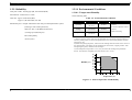
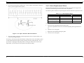
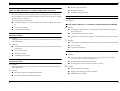
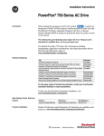
1.2.10 Environmental Conditions
1.2.10.1 Temperature/Humidity
See the following table.
Cutter life : Approx. 2,000 sheets (B0+)
Table 1-9. Environmental Conditions
Approx. 1,000 sheets (B0+) for film
Condition
10~35°C
(50~95°F)
20~80%
Storage
-20~40°C
(-4~104°F)
20~85%
Transportation
-20~60°C
(-4~140°F)
5-85%
(exchange 3 times within printer life)
Steel belt / FFC / Tube/Head unit/CR motor
RTC backup battery
(about 8 years)
Humidity
Operating
Maintenance parts : Ink pad / Maintenance unit/Auto print head optimization system
(exchange per 4,800,000 pass)
Temperature
Notes
• Less than a month at 40°C
(104°F)
• Less than 120 hours at 60°C
(140°F)
• With no freezing
Notes:
1) When storing the printer, make sure the printheads are in the home (capped) position. If
necessary switch power on, wait for the printheads to move to the home position, and then
switch power off.
2) Before transporting the printer, remove the ink cartridges and turn the ink valves screws to
the closed position. Also make sure the printheads are in the home, capped, position. After
transporting the printer, install new ink cartridges.
3) If the temperature drops below -15°C (5°F), the ink in the cartridges and printheads
freezes. The ink thaws completely after three hours at 25°C (77°F).
90
Humidity (%)
80
70
60
50
40
30
20
10
10
15
20
27
30
35
40
Temperature (°C)
Figure 1-3. Print Temperature and Humidity
Product Description
Specifications
25
EPSON Stylus Pro 10000/10000CF
Revision B
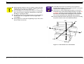
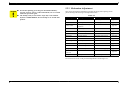
1.2.10.2 Vibration & Shock
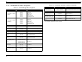
1.2.11 Controller
See the following table.
CPU:
Hitachi SH7709A, 120MHz
Code ROM:
2MB
Font ROM:
None
RAM:
128MB (fixed)
Interfaces:
IEEE1284 interface
USB1.1
Type B interface (2 expansion ports)
Operating System:
Hitachi HI7700 (µITRON 3.0 compatible)
Table 1-10. Vibration and Shock
Condition
Vibration
Resistance
Shock
Resistance
Operating
0.15G
10~55Hz
1G
maximum 1ms
Storage
0.5G
10~55Hz
2G
maximum 2ms
Notes
X/Y/Z directions
Notes:
* Make sure the printhead is capped during transportation and storage. To cap the printhead,
turn the power on (with ink cartridges installed) and turn the power off when the printheads
are capped.
* To thaw frozen ink in the printer or cartridge, leave the printer out at a temperature of 25°C
(77°F) for approximately three hours.
Product Description
Specifications
26
EPSON Stylus Pro 10000/10000CF
Revision B
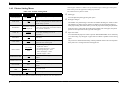
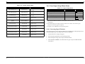
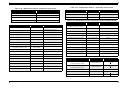
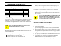
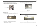
1.2.12 Cutting Specification
Table 1-11. Cut condition and Cut method
Cut condition
Cut method
Manual cut after forward feed
Paper is fed for L1 length and cut in 4 steps.
Manual cut when top edge of paper is
existing close to the rear side, behind the cut
position.
If L1-(L-)<L3, feed L3+(L-) and cut in 4 steps.
L1-(L-)>=3 never occurs.
Manual cut by operating automatic cut ON,
after printing with automatic cut OFF.
If L1-(L-)>=L2, feed media L1 and cut in 3 steps.
If L1-(L-)<L2, feed media(L2-(L+))and cut in 3
steps.
There are two methods to cut a roll paper, automatic and manual cut.
1.2.12.1 Automatic cut of roll media
Automatic cut as shown in the following condition could only be performed on the
approved media.
When cutting sequence is performed on the prohibited media, it may damage the print
heads.
n Mechanical condition
*Distance between cut position and cutter mark: L1=93.9mm
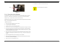
1.2.12.2 Manual cut of roll paper
*Minimum length of 3 step cutting: L1=130mm
Manual cut is possible by the following orders. Manual cut should always be done for the
paper which are not approved to be cut automatically, because the head may be damaged
when automatic cut is performed with such ones.
*Minimum length of 4 step cutting L3 = 130mm
*The fed distance from the cut position is defined as (L+), when media is fed
forward during print or by feed operation.
* The back fed distance from the cut position is defined as (L-), when media is fed
backwards by the reverse feeding operation.
1.
Select "Roll Cutter Off" on the panel.
2.
Press "Cut/ Eject" button.
3.
Paper is automatically fed towards the cutter guide, and printer becomes Off-line.
"Pause" is indicated on the LCD panel.
4.
Adjust cutting position with "Paper Feed +/-" button if necessary.
5.
User slides the cutter among the cutter guide to cut the paper.
6.
After the cut was performed, release pause status by pressing "Pause" button. Then
paper is fed backwards and printer becomes on-line.
* L1 >= L3 is mandatory.
Table 1-11. Cut condition and Cut method
Cut condition
Cut method
Initial cut(The manual cut done by pressing
"Cut/Eject" button, after pulling down the
paper set lever when media is at above the
top edge sensor.
Paper is fed for L1 length and cut in 4 steps.
NOTE: Use the manual cutter attached with the printer.
Cut caused by the completion of the print, or Cut in 3 steps, but in case if (L+) is shorter than L2,
by the reset during print.
this cut is done after feeding L2 length.
Manual cut during print
Cut in 3 steps, but in case if (L+) is shorter than L2,
this cut is done after feeding L2 length.
Manual cut in the normal waiting status
Paper is fed for L1 length and cut in 4 steps.
Product Description
Specifications
27
EPSON Stylus Pro 10000/10000CF
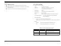
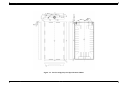
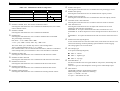
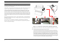
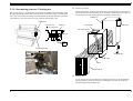
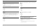
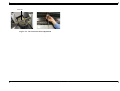
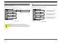
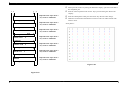
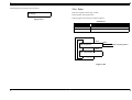
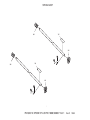
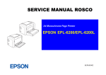
1.2.13 Physical Specification
Revision B
o Weight : 132Kg(including the stand)
o Dimensions of Unit (mm) : 1865(W) x 1225(H) x 710(D)
Figure 1-4. Dimensions of Unit 1
Product Description
Specifications
28
EPSON Stylus Pro 10000/10000CF
Revision B
1.3 Interfaces
1.3.1 Parallel Interface
The EPSON Stylus Pro 10000/10000CF is equipped with parallel and USB interfaces as
well as an expansion slot for an optional Type-B interface. This section provides
information on each of these interfaces.
COMPATIBILITY MODE
Table 1-12. Parallel Interface Specifications
Item
Description
Transmission mode
8-bit parallel, IEEE-1284 compatibility mode
Synchronization
By STROBE pulse
Handshaking
By BUSY and ACKNLG signal
Logic Level
TTL compatible level (IEEE-1284 Level 1 device)
Connector
57-30360 (Amphenol) or equivalent
Note: Use a twisted-pair cable that is as short as possible.
Product Description
Interfaces
29
EPSON Stylus Pro 10000/10000CF
Revision B
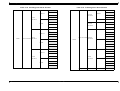
Connector pin assignment and signals are shown below.
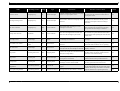
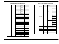
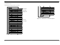
Table 1-13. Connector Pin Assignments and signals (Compatibility Mode)
Pin No.
Signal Name
Return GND Pin
In/Out*
Functional Description
1
-STROBE
19
In
2
DATA0
20
In
3
DATA1
21
In
4
DATA2
22
In
5
DATA3
23
In
6
DATA4
24
In
7
DATA5
25
In
8
DATA6
26
In
9
DATA7
27
In
10
-ACKNLG
28
Out
This signal is a negative pulse indicating that the printer can again accept data.
11
BUSY
29
Out
A high signal indicates that the printer cannot receive data.
12
PE
28
Out
A high signal indicates paper-out error.
13
SLCT
28
Out
Always at high level when the printer is powered on.
14
-AFXT
30
In
Not used
31
-INIT
30
In
The falling edge of a negative pulse or a low signal on this line causes the printer to
initialize. Minimum 50 us pulse is necessary.
32
-ERROR
29
Out
36
-SLIN
30
In
18
Logic H
-
Out
Pulled up to +5 V via 3.9 K ohm resistor.
35
+5V
-
Out
Pulled up to +5 V via 1.0 K ohm resistor.
17
Chassis GND
-
-
Chassis GND.
GND
-
-
Signal GND.
NC
-
-
Not connected
16,33,19-30
15,34
Data reception pulse. Data is read at the falling edge of this pules.
The DATA0 through DATA7 signals represent data bits 0 to7, respectively.
Each signal is at high level when data is logical 1 and low level when data is logical 0.
A low signal indicates printer error condition.
Not used
* In/Out refers to the direction of signal flow from the printer’s point of view.
Product Description
Interfaces
30
EPSON Stylus Pro 10000/10000CF
Revision B
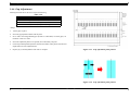
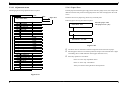
o Data Transmission Timing
DATA
NIBBLE MODE
data byte n
Table 1-15. Transmission Specifications
data byte n+ 1
Description
thold
-STROBE
tsetup
tnext
tstb
BUSY
tready
tbusy
-ACKNLG
treply
tack
Transmission mode
IEEE-1284 nibble mode
Synchronization
Refer to IEEE-1284 specification
Handshaking
Refer to IEEE-1284 specification
Signal level
TTL compatible (IEEE-1284 level 1 device)
Adaptable connector
57-30360 (Amphenol) or equivalent
Data trans. timing
Refer to IEEE-1284 specification
Extensibility request
The printer responds affirmatively when the extensibility request values
are 00H or 04H:
00H: Request Nibble Mode Reverse Channel Transfer
04H: Request Device ID;
Return Data Using Nibble Mode Reverse Channel
Transfer
Device ID
The printer returns the following strings when the device ID is
requested:
<00H><4EH>
MFG: EPSON
CMD: ESCPL2, BDC
MDL: Stylus[SP]Pro[SP]7000
CLS: PRINTER
DES: EPSON[SP]Stylus[SP]Pro{SP]7000
Note: [00H] denotes a hexadecimal value of zero
MDL values depend on the EEPROM setting
tnbusy
Figure 1-5. Data Transmission Timing
Table 1-14. Data transmission times
Parameter
Minimum
Maximum
tsetup
500 ns
-
thold
500 ns
-
tstb
500 ns
-
tready
0
-
tbusy
-
500 ns
tt-out*
-
120 ns
tt-in**
-
200 ns
treply
0
-
tack
Typical 2 us
tnbusy
0
-
tnext
0
-
* Rise and fall time of every output signal
** Rise and fall time of every input signal
Product Description
Interfaces
31
EPSON Stylus Pro 10000/10000CF
Revision B
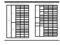
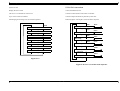
Table 1-16. Connector Pin Assignments - Nibble Mode
Pin No.
Signal Name
Return GND Pin
In/Out*
Functional Description
1
HostClk
19
In
2
DATA0
20
In
3
DATA1
21
In
4
DATA2
22
In
5
DATA3
23
In
6
DATA4
24
In
7
DATA5
25
In
8
DATA6
26
In
9
DATA7
27
In
10
PtrClk
28
Out
Printer clock signal.
11
PtrBusy / DataBit-3,7
29
Out
Printer busy signal and reverse channel transfer data bit 3 or 7.
12
AckDataReq / DataBit-2,6
28
Out
Acknowledge data request signal and reverse channel transfer data bit 2 or 6.
13
Xflag / DataBit-1,5
28
Out
X-flag signal and reverse channel transfer data bit 1 or 5.
14
HostBusy
30
In
In Host busy signal.
31
-INIT
30
In
Not used.
32
-DataAvail / DataBit-0,4
29
Out
36
1284-Active
30
In
18
Logic-H
-
Out
Pulled up to +5 V via 3.9 K ohm resistor.
35
+5V
-
Out
Pulled up to +5 V via 1.0 K ohm resistor.
17
Chassis GND
-
-
Chassis GND.
GND
-
-
Signal GND.
NC
-
-
Not connected.
16,33,19-30
15,34
Host clock signal.
The DATA0 through DATA7 signals represent data bits 0 to7, respectively.
Each signal is at high level when data is logical 1 and low level when data is
logical 0.
Data available signal and reverse channel transfer data bit 0 or 4.
1284 active signal.
* In/Out refers to the direction of signal flow from the printer’s point of view.
Product Description
Interfaces
32
EPSON Stylus Pro 10000/10000CF
Revision B
ECP MODE
Table 1-17. Transmission Specifications
Description
Transmission mode
IEEE-1284 ECP mode
Synchronization
Refer to IEEE-1284 specification
Handshaking
Refer to IEEE-1284 specification
Signal level
IEEE-1284 level 1 device
Adaptable connector
See forward channel
Data trans. timing
Refer to IEEE-1284 specification
Extensibility request
The printer responds affirmatively when the extensibility request values
are 10H or 14H:
10H: Request ECP Mode Reverse Channel Transfer
14H: Request Device ID;
Return Data Using ECP Mode Reverse Channel
Transfer
Device ID
The printer returns the following strings when the device ID is
requested:
<00H><4EH>
MFG: EPSON
CMD: ESCPL2, BDC
MDL: Stylus[SP]Pro[SP]7000
CLS: PRINTER
DES: EPSON[SP]Stylus[SP]Pro{SP]7000
Note: [00H] denotes a hexadecimal value of zero
MDL values depend on the EEPROM setting
Product Description
Interfaces
33
EPSON Stylus Pro 10000/10000CF
Revision B
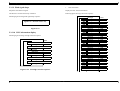
Table 1-18. Connector Pin Assignments - ECP Mode
Pin No.
Signal Name
Return GND Pin
In/Out*
Functional Description
1
HostClk
19
In
2
DATA0
20
In
3
DATA1
21
In
4
DATA2
22
In
5
DATA3
23
In
6
DATA4
24
In
7
DATA5
25
In
8
DATA6
26
In
9
DATA7
27
In
10
PeriphClk
28
Out
Data is transferred from a printer to a host.
11
PeriphAck
29
Out
A printer uses this signal for a flow control of forward direction. Also this signal
offers the data bit 9 that use it to judge whether or not it is information command
information or data to be output on the data signal of reverse direction.
12
nAckReverse
28
Out
A printer does drive to Low and approve nReverseRequest.
13
Xflag
28
Out
X-flag signal and reverse channel transfer data bit 1 or 5.
14
HostAck
30
In
A host uses this signal for a flow control of reverse direction. Also this signal
offers the data bit 9 that use it to judge whether or not it is information command
information or data to be output on the data signal of forward direction.
31
nReverseRequest
30
In
This signal is made a low, to change a channel toward reverse.
32
nPeriphRequest
29
Out
36
1284-Active 30
30
In
18
PeriphLogic-H
-
Out
Always "HIGH". Pulled up to +5 V via 3.9 K ohm resistor.
35
+5V
-
Out
Always "HIGH". Pulled up to +5 V via 1.0 K ohm resistor.
17
Chassis GND
-
-
Chassis GND.
GND
-
-
Signal GND.
NC
-
-
Not connected.
16,33,19-30
15,34
Product Description
Interfaces
In Data or address information are transferred from a host to a printer.
The DATA0 through DATA7 signals represent data bits 0 to 7,respectively.
Each signal is at high level when data is logical 1 and low level when data is
logical 0.
These signals are used to transfer the 1284 extensibility request values to the
printer.
This signal uses to produce a host interrupt.
1284 active signal. "HIGH" in ECP mode
34
EPSON Stylus Pro 10000/10000CF
* In/Out refers to the direction of signal flow from the printer’s point of view.
Revision B
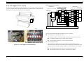
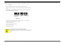
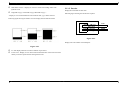
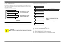
1.3.2 USB
Standard
:“Universal Serial Bus Specifications Revision 1.1”
“Universal Serial Bus Device Class Definition for Printing
Devices Version 1.1”
Bit rate
:12Mbps (Full speed device)
Data encoding
:NRZI
Adaptable connector
:USB series B
Suggested cable length
:2 meters
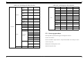
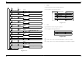
Table 1-19. USB connector pin assignments and signals
Pin no.
Signal name
In/Out
Description
1
VCC
-
Cable power, max. power consumption is 100mA
2
-Data
bi-directional data
3
+Data
bi-directional data, pull up to+3.3V via 1.5K ohm resistor
4
Ground
-
Pin #2
Pin #3
Cable ground
Pin #1
Pin #4
Figure 1-6. USB Pins
NOTE: To use USB interface: set “PARA.I/F=COMPAT.” in the Printer Settings
Menu.
Product Description
Interfaces
35
EPSON Stylus Pro 10000/10000CF
Revision B
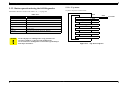
1.3.3 TYPE-B Optional Interface
1.3.4 Complement Item
Type-B interface (level 2, 1200mA type) is supported.
PREVENTION HOSTS FROM DATA TRANSFER TIME-OUT
Reply message (Case of using Type-B I/F card except above):
n Card in Type-B slot 1:
Main type:
Product name:
Emulation type:
Entity type:
MT48p,PW127cl10cpi,PRG(T0xxxx.yyyy.zzzz)rev,SPD0fast
AP1200ma
Stylus Pro 10000 (pigment: Stylus Pro 10000CF)
ESCPL2-00
EPSONLQ2J
When data is received from the parallel interface or the type B interface while no error has
occurred (including the pause condition), the printer receives data a rate of 2 byte/second
while buffer free space is less than 16 kbytes in order to prevent host timeout.
When buffer free space is more than 32kbytes, the 2 byte/second receive rate is cleared, and
receive is halted when free space reaches 16 bytes, and returns to the 2 byte/second rate
when free space reaches 512 kbyte or more.
n Card in Type-B slot 2:
Main type:
Product name:
Emulation type:
Entity type:
MT48p,PW127cl10cpi,PRG(T0xxxx.yyyy.zzzz)rev,
AP1200ma, SPD1fast
Stylus Pro 10000 (pigment: Stylus Pro 10000CF)
ESCPL2-00
EPSONLQ2J
INTERFACE SELECTION
The printer has the parallel interface, the USB interface, the optional interface-1, and
optional interface-2.
These interfaces are selected manually by the default setting mode or selected
automatically.
n Manual selection
One of 4 interfaces can be selected; the parallel interface, the USB interface, the
optional interface-1, and optional interface-2.
n Automatic selection
Select a interface which the printer received data first after power ON. If it passes 10
seconds after interruption of data receiving, it will be idle status (any interface is not
selected ) and will select a interface which the printer received data first.
n Interface state and interface selection
When the parallel interface is not selected, the interface goes into the busy status.Only
reverse communication can be done at this time.
When the printer is initialized or returned to the idle state, the parallel interface
becomes ready status, the USB interface becomes non NACK reply status, and the
option interface resets OFF-LINE bit of Main Status Register (MNSTS).
INIT signal on the parallel interface is not effective while that interface is not selected
or nibble Mode, ECP Mode.
Product Description
Interfaces
36
EPSON Stylus Pro 10000/10000CF
Revision B
INITIALIZATION
There are three kinds of initialization method.
1.
Power-on initialization
This printer is initialized when turning the printer power on.
When printer is initialized, following action is performed.
(a) Initializes printer mechanism.
(b) Clears input data buffer.
(c) Clears print buffer.
(d) Sets default values.
2.
Software initialization
The ESC @ command also initializes the printer.
When printer is initialized, following action is performed.
(a) Clears print buffer.
(b) Sets default values.
3.
Panel initialization
This printer is initialized when pushing the Pause button more than 3 seconds, or
printer recognized the -INIT signal.
When printer is initialized, following action is performed.
(a) Eject a paper. (If roll paper, it cuts paper skipping print part when Paper Source =
Auto Cut, it doesn’t cut when Paper Source = Cutter Off with SelecType)
(b) Cap the print head.
(c) Clears input data buffer.
(d) Clears print buffer.
(e) Sets default values.
Left margin
:
1st character
Character pitch
:
10 CPI
Print mode
:
Text mode (non-raster graphics mode)
DEFAULT SETUP VALUES
Default setup values are as follows. The parameters for items which may be saved for panel
setup, default setup, and remote commands are used as default values.
Page position
:
Current paper position as page start position
Line feed
:
1/6"
Right margin
:
437th character
Product Description
Interfaces
37
EPSON Stylus Pro 10000/10000CF
Revision B
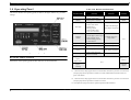
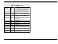
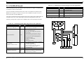
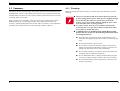
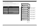
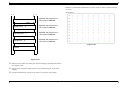
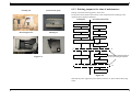
1.4 Operating Panel
Table 1-20. Buttons and Functions
This section describes the operating panel, the buttons, the lights, and the way you make
settings.
Button
(Second function)
Function
(Normal)
SelecType
Function
Power-On
Function
Power
Power on/off
N/A
N/A
N/A
Maintenance
Mode
Pause
(Reset)
SelecType
Cut/Eject
(Enter)
Each button on the operating panel and their functions are described below.
• Printing
Printer status menu
Selection of SelecType
• Except above
menu (major categories)
Selectype mode
Cutter replace menu
(press for 5 seconds)
• Eject sheet*3.
• Cut roll paper (Auto Cut)*3
Confirms and saves
• Feed roll paper to the
setup values
manual cutting position
(cutter OFF)*3.
Paper Feed ↑
Paper feed (reverse)*1
Increase setup value
Paper Feed ↓
Paper feed (forward)*2
Decrease setup value
Paper Source
(Item)
Selects paper source
Selection of SelecType
items (minor categories)
Figure 1-7. Operating Panel
BUTTONS AND FUNCTIONS
• Switch -pause/ready
• Reset (press 3 seconds)
Cleaning
Paper Source+
Eject+
Paper Feed ↓
Paper Source+
Eject+
Cleaning
Cleaning Cleans all heads
(press for 3 seconds)
N/A
N/A
Maintenance
Mode 2
N/A
Firmware
reload
Notes:
*1 : 1.27cm/second (5.0cps) paper feed for 2 seconds after the button is pressed. 12.7cm/second
(50.0cps) paper feed if pressed for a further 2 seconds. Maximum feed of 20cm with one
press of the button.
*2 : 1.27cm/second (5.0cps) paper feed for 2 seconds after the button is pressed. 12.7cm/second
(50.0cps) paper feed if pressed for a further 2 seconds.
*3 : Interrupts ink drying and runs the specified operation.LED indicators
Product Description
Operating Panel
38
EPSON Stylus Pro 10000/10000CF
Revision B
LEDS
Table 1-21. LED Indicator Lights
LED
Operate
Status
• On
• Blink
• On
Paper Out
• Blink
Pause
Ink Out Y
Ink Out LM
Ink Out LC
Ink Out M
Ink Out C
Ink Out K
Roll Auto Cut
Roll, Cutter Off
Sheet
•
•
•
•
•
•
On
Blink
On
Blink
On
Blink
•
•
•
•
•
•
•
•
•
•
•
•
•
•
On
Blink
On
Blink
On
Blink
On
Blink
On
Blink
On
Blink
On
Blink
Product Description
Condition
• Printer power ON.
• Printer processing data, or in power OFF sequence.
• Paper out, end of roll, Paper mismatch error, paper set
lever is released, or paper is thick for cleaning
• Paper jam error, paper cutting error, paper not straight,
paper check error, or problem with paper output
(sheet)
• Paused
• Cleaning print head, or ink drying.
• Yellow ink end, or dye/pigment yellow ink
• Yellow ink low.
• Light magenta ink end, or dye/pigment light magenta
ink
• Light magenta ink low.
• Light cyan ink end, or dye/pigment light cyan ink
• Light cyan ink low.
• Magenta ink end, or dye/pigment magenta ink
• Magenta ink low.
• Cyan ink end, or dye/pigment cyan ink
• Cyan ink low.
• Black ink end, or dye/pigment black ink
• Black ink low.
• Roll, Auto cut is selected.
• Paper mismatch error.
• Roll, Cutter off is selected.
• Paper mismatch error.
• Sheet is selected.
• Paper mismatch error.
Operating Panel
39
EPSON Stylus Pro 10000/10000CF
Revision B
1.4.1 Indicator Status in Normal Mode
Table 1-24. Pause Indicator
Table 1-22. Operate Indicator
Printer Status
Indicator
With power on and in any status other than
those listed below.
On
While processing data and during power off
sequence
Blink
Fatal error
Blink
Reset, timer IC reset/NVRAM clear
On
Table 1-23. Paper Out Indicator
Printer Status
Indicator
Out of paper, end of roll
On
Roll paper and sheet sizes are different
On
Paper set lever in release position
On
Paper is too thick to perform cleaning
On
Paper jam
Printer Status
Indicator
Print ready
Off
In SelecType mode
Off
During pause
Off
During ink drying time
Blink
During ink sequence
Blink
Other errors
Off
Fatal error
Blink
Reset, timer IC reset/NVRAM clear
On
Table 1-25. Ink Out Indicators
Printer Status
Indicator
On
Blink
Out of specified ink
No cartridge for specified ink
Wrong cartridge for specified ink
Illegal cartridge for specified ink
Paper cutting error
Blink
Ink level low
Blink
Paper not straight
Blink
Fatal error
Blink
Paper check error
Blink
Reset, timer IC reset/NVRAM clear
On
Problem with paper output (sheet)
Blink
Fatal error
Blink
Printer Status
Indicator
Reset, timer IC reset/NVRAM clear
On
Selected paper source
On
Maintenance call
On for 100ms at intervals
of 5 seconds
Fatal error
Blink
Difference with roll paper and sheet
Blink
Reset, timer IC reset/NVRAM clear
On
Product Description
Table 1-26. Paper Source Indicator
Operating Panel
40
EPSON Stylus Pro 10000/10000CF
Revision B
1.5 Operating Panel Messages
Table 1-27. Operating Panel Messages (continued)
Display Message
Printer status and error messages appear on the operating Panel display. The table below
lists the messages.
Table 1-27. Operating Panel Messages
Display Message
Meaning
SERVICE REQ. nnnnnnnn
Fatal error - see “Service Requests”
TURN PWR OFF AND ON
Turn the printer off and on to reinitialize
RESET
TRANSPORT PREP nn%
POWER OFF
Paper Set lever is in the released and cannot continue
or begin a print, cleaning, or initialization sequence.
INK OUT
READY *
WAIT *
INK CHARGING nnn%
INK DRY xx MIN *
Product Description
LOAD PAPER
The Paper Set Lever is in the released position (before
printing). Pull the Paper Set lever forward to the set
position
PAPER JAM
Both front and rear paper sensors detect paper and
there is a carriage over-current or out of step error. This
is due to:
• Paper is jammed inside the printer
• Paper is obstructing the carriage path during feeding
or cutting operation.
Preparing to shut down.
SECURE PAPER LEVER
OPTION I/F ERROR
Wrong paper loaded or wrong paper source selected on
operating Panel.
See “Transportation Mode”
The cover is open. The carriage stops in place, and the
printhead can be damaged if the head remains out of
the capped position for a long period of time.
PAPER NOT CUT
Paper skewed more than 3mm between the leading and
following edges. Check the printout for skew and make
sure no ink was fired onto the platen.
UNABLE TO PRINT
When trying to print a test or adjustment pattern, one of
the following occurs:
• Paper not loaded
• Ink cartridge not loaded
• Paper detection error
RELOAD PAPER
• The paper was loaded too far forward and cannot be
backward fed to the proper position.
• The paper’s horizontal position exceeds the normal
printable area when the paper is loaded.
• The paper’s horizontal position exceeds the normal
cutting area after printing.
• The cut sheet is too long and cannot be ejected
properly.
• Recovery from cutter error.
REMOVE PAPER
Loaded paper is too thick to perform timer cleaning
An unsupported Type-B interface card is installed.
Can receive and print data.
Resetting Timer IC
Clearing NVRAM
Performing reset operation
Performing ink sequence operation
Initializing the printer
Initializing the paper
Initial charging of ink - shown in percent completed
Printer did not cut the paper completely, or the cut
piece still remains over the paper sensor
PAPER NOT STRAIGHT
One or more cartridges are not installed
• A predetermined amount of ink has been consumed
after the cartridge has entered the near-end
condition.
• A near-end cartridge has been removed and reinstalled.
Waiting for paper initialize start trigger
LOAD xxx PAPER
In the process of re-initializing.
COVER OPEN
NO INK CARTRIDGE
PRESS PAUSE BUTTON
Meaning
Printer waits xx minutes before the next print job to
allow enough time for ink to dry on previous print job.
Operating Panel Messages
PAUSE
Pause state.
41
EPSON Stylus Pro 10000/10000CF
Revision B
1.6 SelecType Settings
Table 1-27. Operating Panel Messages (continued)
Display Message
Meaning
INK LOW
When total dots fired = 90%, cartridge enters near-end
condition. Remaining ink = A1 at 100% duty
MAINTENANCE REQ. nnnn
Printer requires maintenance - see “Maintenance
Request” on page 49
PRINTING *
Processing print data.
PAPER OUT
• No paper loaded
• End of roll paper (printer stops feeding)
• End of sheet paper (when paper feeds to eject
position, put hand under the sheet and press Cut/
Eject to release)
Notes*:Only when PG setting = WIDE, 20th character is "H" on LCD.
o Entering SelecType mode
To access the operating Panel settings, press the SelecType button while the printer is not
printing. The printer enters the SelecType mode and cannot print.
o Using SelecType mode
1.
Repeatedly press the SelecType button to view the SelecType menus which appear in
the order shown below.
Table 1-28. SelecType Menus
Display Message
PRINTER SETTING MENU
TEST PRINT MENU
PRINTER STATUS MENU
PAPER CONFIG. MENU
Product Description
For details
Printer Setting Menu
Test Print Menu
Printer Status Menu
Paper Configuration Settings
CUTTER REPLACE MENU
Cutter Replacement Menu
HEAD ALIGNMENT MENU
Head Alignment Menu
2.
Press the Item button to select the choice shown in the LCD display.
3.
Press the SelecType button to view the options for that Item.
4.
Press the “+” button or “-” button to view the available values for an option.
5.
Press the Enter button to record the current option or to execute the operation shown in
the display.
SelecType Settings
42
EPSON Stylus Pro 10000/10000CF
Revision B
o Exiting SelecType mode
Select one of the following methods to exit SelecType mode:
n Press the Pause button while in SelecType mode; the printer is ready to print.
n Perform the printer initialization.
n Print a status sheet.
n Print a nozzle check pattern.
n Replace the cutter.
n Press the SelecType button several times at the top level of SelecType menus.
n Press the SelecType button one time at the second level of SelecType menus.
Product Description
SelecType Settings
43
EPSON Stylus Pro 10000/10000CF
Revision B
1.6.1 Printer Setting Menu
12mm of paper clearance is added to the top and bottom edges to make paper feeding more
stable and to prevent the paper from rubbing the printheads.
The underlined item equals the default.
Table 1-29. Printer Setting Menu
Display Message
Options
PLATEN GAP
Auto,
Wide, Narrow
Adjusts the platen gap. (Normally, leave set to
Auto.)
PAGE LINE
ON
OFF
When Auto Cut Off is selected on the operating
Panel, this setting determines whether a line for
manual cutting is printed.
INTERFACE
Notes
Determines which interface the printer checks
Auto,Parallel,USB,Op
for data. Auto continuously checks all interfaces
tion1,Option2
and is good for normal use.
PARA. I/F
Compat
ECP
IEEE1284.4
ON
OFF
CODE PAGE
PC437
PC850
Determines the data transfer rate when using
this interface.(Normally, leave set to
Compatible.)
IEEE1284.4
Character code setting. (PC437: expanded
graphics/PC850: multi-lingual)
You can adjust the platen gap using this option.
o Roll paper margin
T/B 15MM = the printed image is the same size whether the margin is 15mm or 3mm.
The difference is 12mm of paper clearance is added to the top and bottom edges to
make paper feeding more stable and to prevent the paper from rubbing the printheads.
If the print area is greater than the width of the printable area of the paper, the printer
ignores the extra print data on the right side of the paper.
o Paper size check
You can disable the paper size check to prevent “RELOAD PAPER” errors which may
occur when using very thin paper or paper with low reflective qualities such as tracing
paper.
The print area is determined manually, and the printheads will fire ink onto the platen
if the print area is set larger than the actual paper size.
Roll sheet margin setting.
• Top/Bottom 15mm*
top and bottom margins = 15mm
left and right margins = 3mm
• 15mm: all margins = 15mm
• 3mm all margins = 3mm
ROLL MARG
T/B 15MM
15MM
3MM
PAPER SIZE CHK
ON
OFF
Determines whether the paper size check is
enabled
PAPER ALIGN CHK
ON
OFF
Determines whether the paper skew check is
enabled
INIT. PANEL
Exec.
Initializes operating Panel setup values to their
defaults
AUTO NOZZLE
CHK.
o Platen gap
PAGE, PASS, OFF
Auto nozzle check
(TBD)
AUTO CLEANING
ON, OFF
Auto cleaning
Notes:
* The printed image is the same size whether the margin is 15mm or 3mm. The difference is
Product Description
SelecType Settings
44
EPSON Stylus Pro 10000/10000CF
Revision B
1.6.2.2 Status sheet
1.6.2 Test Print Menu
:Built
in font
ple
Table 1-30. Test Print Menu
Display Message
Item
Notes
NOZZLE CHECK
Print
Check the printout, any missing lines mean the
nozzle(s) are clogged.
STATUS SHEET
Print
Prints the current printer settings.
1.6.2.1 Nozzle check
Figure 1-8. Nozzle check pattern
o Order of colors from left - black, cyan, magenta, yellow, light magenta, light cyan.
o Each parameter indicates following;
<xxxx>: version of I/F controller (4 letters)
<yyyy>: version of engine controller (4 letters)
<zzzz>: version of ESC/P3 controller (4 letters)
*<zzzz> is blank when ESC/P3 controller is not connected.
<aaaaaaa> : total ink counter just before print the last nozzle check pattern (7 figures)
<bbbbbbb> : total ink counter just before print the nozzle check pattern (7 figures)
<ccccccc> : value of <aaaaaaa>-<bbbbbbb> (7 figures)
<ddddd.d> : total paper counter just before print the last nozzle check pattern (5.1
figures)
<eeeee.e> : total paper counter just before print the nozzle check pattern (5.1 figures)
<fffff.f> : value of <ddddd.d>-<eeeee.e>(5.1 figures)
XX-XX-XX-XX-XX-XX
XX-XX-XX-XX-XX-XX
Type B
-1
:Installed
Type B
-2
:Uninstalled
Photo Accelerator
:Installed
===Current Setting================================================
Head Gap
:Auto
Border Line
:On
Interface
:Parallel
Parallel
I/F
:ECP
IEEE1284.4
:On
Code Page
:PC437
Version
:T0xxxx
.yyyy[.zzzz]
Margin
:T/B15mm
Paper Size Check
:ON
Paper Align Check
:ON
Parallel I/F
:ECP
IEEE1284.4
:On
Page Count
:123456
Version
:T0xxxx.yyyy[.zzzz]
===Ink Cartridge===================================================
Manufacturer :EPSON GEN
UINE INK EPSON GENUINE INK EPSON GENUINE I
Ink Type
:Pigment
Pigment
Pigment
Ink Color
:Cyan
Magenta
Yellow
Ink Capacity :500ml
500ml
500ml
Ink Left
:E*****F
E*****F
E*****F
Production Date
:`00/03
`00/03
`00/03
Expire Date
:`01/10
`01/10
`01/10
Ink Life
:06 months
06 months
06 months
Passed
:02 months
02 months
02 months
Printable Sheet:120 pages
120 pages
120 pages
-----------------------------------------------------------------Manufacturer :EPSON GENUINE INK EPSON
GENUINE INK EPSON GENUINE INK
Ink Type
:Pigment
Pigment
Pigment
Ink Colo
:Black
LightCyan
LightMagenta
Ink Capacity :500ml
500ml
500ml
Ink Left
:E*****F
E*****F
E*****F
Production Date:`00/03
`00/03
`00/03
Expire Date
:`01/10
`01/10
`01/10
Ink Life
:06 months
06 months
06 months
Passed
:02 months
02 months
02 months
Printable Sheet:120 pages
120 pages
120 pages
===Supplies========================================================
Ink
:xxxxxx.x g
Paper
:xxxxxxx cm
Cutter Life
:E*****F
Ink Pad
:E*****F
CR Motor
:E*****F
PF Motor
:E*****F
Head
:E*****F
Cleaner
:E*****F
Figure 1-9. Status sheet
Product Description
SelecType Settings
45
EPSON Stylus Pro 10000/10000CF
Print status sheet with following specification.
o Paper Size :A4
o Font :Built-in font
Revision B
1.6.3 Printer Status Menu
All consumable items and maintenance parts either run out of their contents or wear out. To
determine how much contents (ink) or useful life remains, compare the message and value
shown on the operating Panel display to the corresponding value below and the messages in
the table below.
E*****
E****
E***
E**
E*
E
F
F
F
F
F
F
100~81% full/life remaining
80~61% full/life remaining
60~41% full/life remaining
40~21% full/life remaining
20~1% full/life remaining (generates a warning)
Less than 1% full/life remaining (generates an error)
Table 1-31. Printer Status Menu
Items
LCD panel display
Firmware version
VERSION
Ink used per page
INK USED/PAGE
Printable pages of ink (C)
REMAIN INK C
xxxxxxxPG
Printable pages of ink (M)
REMAIN INK M
xxxxxxxPG
Printable pages of ink (LC)
REMAIN INK LC
xxxxxxxPG
Printable pages of ink (LM)
REMAIN INK LM
xxxxxxxPG
Printable pages of ink (Y)
REMAIN INK Y
xxxxxxxPG
Printable pages of ink (K)
REMAIN INK K
xxxxxxxPG
Total ink counter
INK USED
xxxxxxx.xg
Total paper counter
PAPER USED
Clear total ink counter
Clear total paper counter
Product Description
Values
T0xxxx. Yyyy[.zzzz]
xx.xg
xxxxxxx.xcm
INK COUNTER CLR. EXEC.
PAPER COUNTER CLR. EXEC.
Ink remaining (K)
INK LEFT-K
0%,nn%,E*F,E****F,E***F,E****
F,E*****F
Ink remaining (C)
INK LEFT-C
0%,nn%,E*F,E****F,E***F,E****
F,E*****F
Ink remaining (M)
INK LEFT-M
0%,nn%,E*F,E****F,E***F,E****
F,E*****F
SelecType Settings
46
EPSON Stylus Pro 10000/10000CF
Revision B
1.6.4 User Paper Setup Menu Items
Table 1-31. Printer Status Menu
Items
LCD panel display
Values
Ink remaining (LC)
INK LEFT-LC
0%,nn%,E*F,E****F,E***F,E****
F,E*****F
Ink remaining (LM)
INK LEFT-LM
0%,nn%,E*F,E****F,E***F,E****
F,E*****F
INK LEFT-Y
0%,nn%,E*F,E****F,E***F,E****
F,E*****F
Ink remaining (Y)
Table 1-32. Paper Setup Menu
Items
LCD panel display
Paper select
PAPER NUMBER
Print paper thickness detection pattern
THICK. PAT.
Select paper thickness number
PAPER THICK. NO.
Ink drying time
DRYING TIME
Vacuum
SUCTION
F E,F *E,F **E,F ***E,F
****E,F*****E
Values
STD,1~4 *1
PRINT *3
1~17 *2
0 MIN~30 MIN
Cutter life monitor
CUTTER LIFE
Total number of documents
printed
TOTAL PRINTS
Waste ink count
WASTE INK
F E,F *E,F **E,F ***E,F
****E,F*****E
CR motor life monitor
CR MOTOR
F E,F *E,F **E,F ***E,F
****E,F*****Es
PF motor life monitor
PF MOTOR
F E,F *E,F **E,F ***E,F
****E,F*****E
1.6.4.1 Detecting Paper Thickness
Head unit life monitor
HEAD UNIT
F E,F *E,F **E,F ***E,F
****E,F*****E
This option allows the user to detect the thickness of available paper, and register up to four
user-defined paper types. Ink drying time can also be registered.
Cleaning unit life monitor
CLEANER
F E,F *E,F **E,F ***E,F
****E,F*****E
1.
Load a sheet of A4 or larger size paper.
2.
Press the SelecType button to enter SelecType mode.
3.
Select the Paper Config. menu, and press the Item button.
4.
Select PAPER NUMBER, one of STD and four types. (If you use EPSON media,
select STD.)
Product Description
nnnnnn
NORM, LOW
*1 When Standard paper is selected, the items of paper thickness detection pattern print and
paper thickness selected number are not displayed. Only when paper 1~4 are selected, they
are displayed.
*2 The default display for the paper thickness number is the number used with the paper
thickness for which the gap was adjusted.
*3 It displays "PAT. PRINTING" during printing pattern.
SelecType Settings
47
EPSON Stylus Pro 10000/10000CF
5.
Revision B
Press Item and confirm that “THICK. PAT. = Print” appears on the display. Then press
Enter to print the paper thickness pattern.
1.6.5 Cutter Replacement Menu
Print the Status Sheet from the Test Print menu in SelecType mode and see page 45 for
information on determining when the cutter needs to be replaced.
The following table includes the steps/messages that must be followed to replace the cutter.
Table 1-33. Cutter Replace Menu
Items
LCD panel display
Values
Replace cutter
CUT. REPLACE
EXEC.
Cover open guide
OPEN LOWER COVER
-
Cutter replacement guide
REPLACE CUTTER
-
Cover close guide
CLOSE LOWER COVER
-
If you need to replace the cutter:
Figure 1-10. Paper Thickness Detection Pattern
6.
1.
Select the cutter replacement menus from the panel.
*The cutter replacement menu can be selected with pushing SelecType button for 5
sec.
2.
Open the cover on the guide.
3.
Replace the cutter blade following the guide.
4.
Close the cover on the guide.
Select the number of the most vertically aligned pair of lines, and press Enter. (#5 is
correct in the example below).
If necessary, select Drying Time from the Paper Config menu to select an automatic period
of time that the printer will pause printing to let the previously printed sheet dry. Also, to
prevent thin or light paper from getting stuck over the paper suction holes in the Lower
Paper Guide, you can select Low (50% power) as the Suction setting.
Product Description
SelecType Settings
48
EPSON Stylus Pro 10000/10000CF
Revision B
1.6.6 Gap Adjustment
Selecting this mode allows the user to adjust the following.
Table 1-34.
Items
Paper thickness (in 0.1mm units)
Bi-d adjustment 1 (240cps, VSD1, Small)
Bi-d adjustment 2 (300cps, VSD2, Large)
<Setup>
1.
Set the paper in place.
2.
Select the gap adjustment menu from the panel.
3.
Set to ’STD’ when using EPSON paper (0.2mm or 1.2mm thick). For other paper, set
thickness in units of 0.1mm.
4.
Select the adjustment pattern to be printed (all or individual), and print.
5.
Check the printed adjustment patterns and enter the number of the pattern with the least
displacement for each adjustment item.
6.
Repeat (4)~(5) until adjustment of all items is complete.
Figure 1-11. Gap Ajustment print pattern
Figure 1-12. Gap Ajustment print pattern
Product Description
SelecType Settings
49
EPSON Stylus Pro 10000/10000CF
Revision B
1.7 Maintenance Mode
Table 1-35. Gap Ajustment Menu
Display Messages
Item
Notes
PAPER THICK
STD
0.0~1.6mm
Select the thickness, to 0.1mm, of the paper you
are using to check the platen gap. Normally,
leave set to Standard.
ADJUST. PATT.
All
#1~12
Selects which patterns to print. (All patterns or
selected patterns only.)
#1
1~8~15
Bi-D adjust 1 (240cps, VSD1, Small)
#2
1~8~15
Bi-D adjust 2 (300cps, VSD2, Large)
*1 When Standard paper is selected the following paper is selected as a result the of detection of
paper thickness.
0.2mm if the paper thickness sensor detects thin paper.
1.2mm if the paper thickness sensor detects thick paper.
*2 Paper thickness is inputted at first to print a pattern close to last setting, then it reduce
repetition of operation.
1.7.1 Outline
C A U T IO N
o Startup
1.
The maintenance mode display is selected by switching power ON while pressing the
Pause button.
o Operation
1.
The Setup items select mode is selected by pressing the Item button once. The first
Setup item on the Setup menu is displayed. The display is in the ’[Item]=[current setup
value]*’ format. The ’*’ represents the current setup value.
2.
The Setup items are displayed in the ’[Item]=[current setup value]*’ format in turn
each time the Item button is pressed.
3.
With the Setup items displayed, the settable values are displayed in turn in the
’[Item]=[current setup value](*)’ format each time the setup value + button or setup
value - button is pressed. The ’*’ is only displayed when the displayed setup value is
the current value. The values are displayed in reverse order by pressing the setup value
- button. If the setup value + button or setup value - button is pressed for more than the
set period of time, the setup values are displayed periodically in forward or reverse
order respectively. The cursor moves among column separated by “:“ character
(ie:”XX1=<nn>:<mm>”) if the cleaning button is pushed.
4.
When the Enter button is pressed, the displayed setup value is entered and recorded as
the current setup value, and any associated operations are run. No operation occurs if
’*’ is already displayed.
5.
When the Item button is pressed in the Setup item select mode, the system returns to
the maintenance mode.
*3 It displays "PAT. PRINTING" during printing pattern.
Product Description
The following explanations regarding operating Panel service
functions are for service and support purposes only; do not share this
information with the user.
Maintenance Mode
50
EPSON Stylus Pro 10000/10000CF
Revision B
o Termination
1.
The printer is ready for printing following reset after selecting the panel display
language.
2.
Switch power OFF > ON.
o Maintenance mode setup items : Refer to the following table
Product Description
Maintenance Mode
51
EPSON Stylus Pro 10000/10000CF
Revision B
.
Table 1-36. Maintenance Mode Setup Items
Table 1-36. Maintenance Mode Setup Items
Item
Panel display
Item
Panel display
Print hexadecimal dump
HEX DUMP
PRINT *1
XX5=<nn>:<mm>
Panel display language select
LANGUAGE
ENGLISH, FRENCH,
ITALIAN, GERMAN,
SPANISH, PORTUGUE
Paper feed adjustment mode
table5
(Dye/Pigment, PH=less than
0.5mm)
Paper feed adjustment offset
1 (Pigment)
XX0=<nn>
<nn>:-32 - 0 - + 32
<nn>:-32 - 0 - + 32
Setup value
Parallel interface mode
PARA. I/F
ECP, COMPAT
Set IEEE1284.4
IEEE1284.4
ON, OFF
Paper feed adjustment offset
2 (Dye)
XX0=<nn>
Auto nozzle check
AUTO NOZZLE CHK.
ON, OFF
System table version
XXS=<mmmmm><n>
Ink information (K)
K CARTRIDGE INFO
(Ink information menu)
User table version
XXU=<nn>
Ink information (C)
C CARTRIDGE INFO
(Ink information menu)
Ink information (M)
M CARTRIDGE INFO
(Ink information menu)
Ink information (Lc)
Lc CARTRIDGE INFO
(Ink information menu)
Ink information (Lm)
Lm CARTRIDGE INFO
(Ink information menu)
Ink information (Y)
Y CARTRIDGE INFO
(Ink information menu)
Gap adjustment menu
HEAD ALIGNMENT MENU
Paper feed adjustment mode
table1
(Pigment, PH=less than
0.1mm)
XX1=<nn>:<mm>
<nn>:00H-C9H
<mm>:00H-09H,FFH
Paper feed adjustment mode
table2
(Pigment, PH=less than
0.2mm)
XX2=<nn>:<mm>
<nn>:00H-C9H
<mm>:00H-09H,FFH
Paper feed adjustment mode
table3
(Dye, PH=less than 0.1mm)
XX3=<nn>:<mm>
<nn>:00H-C9H
<mm>:00H-09H,FFH
Paper feed adjustment mode
table4
(Dye, PH=less than 0.2mm)
XX4=<nn>:<mm>
<nn>:00H-C9H
<mm>:00H-09H,FFH
Product Description
Setup value
<nn>:00H-C9H
<mm>:00H-09H,FFH
<mmmmm>:EG F/W version
<nn>: 00H - FFH
*1 When hexadecimal dump mode is executed, "HEX MODE" is displayed.
Maintenance Mode
52
EPSON Stylus Pro 10000/10000CF
Revision B
1.7.2 Hexadecimal Dump
1.7.3 Panel Display Language Select
The hex dump function allows data sent to the printer to be printed and displayed in
hexadecimal format.
Selecting this mode allows the user to select English, French, Italian, German, Spanish,
Portuguese for display on the LCD.
One line contains 16 data items in hexadecimal format, with the equivalent characters
printed at the right of each line.
1.7.4 Auto nozzle check
If no equipment characters exist (eg control codes) a full stop is printed.
Each 16 data items is printed, and if the last line contains less than 16 data items, this line is
printed by pressing the Pause button.
SelecType is not possible in the hex dump mode.
The use of this function allows the user to check that data has been sent correctly from the
computer to the printer.
Select Auto nozzle check OFF/ON.
The default is ON.
1.7.5 Ink information menu
It display ink information recorded in CSIC.
This mode is terminated by switching power OFF.
Table 1-37. Information Recorded in CSIC
Item
Panel display
Setup value
MANUFACT.C(-Lm)
“EPSON“
Ink Color
CART.C(-Lm)
CYAN/
MAGENTA?YELLOW/
BLACK/L.CYAN/
L.MAGENTA
Ink type
INK TYPE C (-Lm)
DYE/PIGMENT
Ink capacity
INK CAP. C(-Lm)
500ML/200ML
Ink remaining
INK LEFT C(-Lm)
E F,E* F,E** F,E***
F,E**** F,E*****F
Product date
PROD.DATE C(-Lm)
<YY>/<MM>
Expire date
EXPIRE DATE C-Lm
<YY>/<MM>
Ink life
INK LIFE C(-Lm)
<MM>MONTH
Passing time
PASSED C(-Lm)
<MM>MONTH
Printable life
LIFE C(-Lm)
<nnnn>PAGE
Manufacture logo
Manufacture loro : Manufacture information saved in CSIC of each ink cartridge is displayed.
Ink Color : Ink color information saved in CSIC of each ink cartridge is displayed.
Product Description
Maintenance Mode
53
EPSON Stylus Pro 10000/10000CF
Revision B
Ink capacity : Ink capacity information saved in CSIC of each ink cartridge is displayed.
1.8 Maintenance Mode 2
Ink remaining : Ink remaining of each ink cartridge is displayed.
Product date : Product date information saved in CSIC of each ink cartridge is displayed with
C A U T IO N
<YY>/<MM> form.
Expire date : Ink expire date information saved in CSIC of each ink cartridge is displayed.
Ink life : Ink life information saved in CSIC of each ink cartridge is displayed.
Passed time : Passed time after opened of each ink cartridge is displayed.
The following explanations regarding operating Panel service
functions are for service and support purposes only; do not share this
information with the user.
o Startup
1.
The maintenance mode 2 display is selected by switching power ON while pressing the
Paper source, Cut/Eject, and Paper Feed ↓ buttons.
o Operation
1.
The Setup items select mode is selected by pressing the Item button once. The first
Setup item on the Setup menu is displayed. The display is in the ’[Item]=[current setup
value]*’ format. The ’*’ represents the current setup value.
2.
The Setup items are displayed in the ’[Item]=[current setup value]*’ format in turn
each time the Item button is pressed.
3.
With the Setup items displayed, the settable values are displayed in turn in the
’[Item]=[current setup value](*)’ format each time the setup value + button or setup
value - button is pressed. The ’*’ is only displayed when the displayed setup value is
the current value. The values are displayed in reverse order by pressing the setup value
- button. If the setup value + button or setup value - button is pressed for more than the
set period of time the setup values are displayed periodically in forward or reverse
order respectively.
4.
When the Item button is pressed, the displayed setup value is entered and recorded as
the current setup value, and any associated operations are run. No operation occurs
if’*’ is already displayed.
5.
When the Item button is pressed in the Setup item select mode, the system returns to
the maintenance mode 2.
o Termination
1.
Switch power OFF > ON.
o Maintenance mode 2 setup items : Refer to the following table.
Product Description
Maintenance Mode 2
54
EPSON Stylus Pro 10000/10000CF
Revision B
Table 1-39. Maintenance Mode 2 - (NVRAM) counter menu
Table 1-38. Maintenance Mode 2 Setup Items (Top menu)
Item
Panel display
VIEW COUNTERS MENU
Head unit (LM) life counter value
HEAD LM
0~4294967295 (Decimal)
Counter initialize menu
CLEAR COUNTERS MENU
Head unit (Y) life counter value
HEAD Y
0~4294967295 (Decimal)
Adjustment / setup menu
SERVICE CONFIG MENU
Cleaning unit life counter value
CLEANER
0~4294967295 (Decimal)
Maintenance information menu
(TBD)
Item
Panel display
Counter indication menu
Setup value
Table 1-40. Maintenance mode 2 setup items (counter initialize menu)
Table 1-39. Maintenance Mode 2 - (NVRAM) counter menu
Panel display
Setup value
Initialize NVRAM, timer, life
counter, mechanical counter
INIT. ALL
EXEC.
Initialize NVRAM
INIT. NVRAM
EXEC.
Initialize RTC
RTC INIT
<YY>/<MM>/<DD>/<HH>
Initialize cutter life total
INIT. CUT TOTAL
EXEC.
Initialize CR motor life
INIT. CR MTR
EXEC.
Item
Panel display
Ink remaining (K) counter value
INK K
0~4294967295 (Decimal)
Ink remaining (C) counter value
INK C
0~4294967295 (Decimal)
Ink remaining (M) counter value
INK M
0~4294967295 (Decimal)
Ink remaining (LC) counter value
INK LC
0~4294967295 (Decimal)
Ink remaining (LM) counter value
INK LM
0~4294967295 (Decimal)
Initialize CR motor life total
INIT. CR TOTAL
EXEC.
Ink remaining (Y) counter value
INK Y
0~4294967295 (Decimal)
Initialize PF motor life
INIT. PF MTR
EXEC.
Cutter life counter value
CUTTER
0~4294967295 (Decimal)
Initialize head unit
INIT. HEAD
EXEC.
Cutter life total counter value
CUTTER TOTAL
0~4294967295 (Decimal)
Initialize cleaning unit
INIT. CLEANER
EXEC.
Total prints counter value
TTL PAGES
0~4294967295 (Decimal)
Initialize total printed pages counter
INIT. TTL PR
EXEC.
Waste ink counter A value
WAST.INK A
0~4294967295 (Decimal)
Initialize ink capacity
INIT. INK
EXEC.
Waste ink counter B value
WAST.INK B
0~4294967295 (Decimal)
Initialize waste ink capacity
INIT. WA. INK
EXEC.
CR motor life counter value
CR MOTOR
0~4294967295 (Decimal)
Clear head error
CLR HEAD ERROR
EXEC.
CR motor life total counter value
CR TOTAL
0~4294967295 (Decimal)
Table 1-41. Maintenance mode 2 setup items
PF motor life counter value
PF MOTOR
0~4294967295 (Decimal)
Item
Panel display
Setup value
Head unit (K) life counter value
HEAD K
0~4294967295 (Decimal)
BID OFFSET #1
-4~0~+4
Head unit (C) life counter value
HEAD C
0~4294967295 (Decimal)
Bi-D offset setting #1
(VSD1, 240CPS, Small)
Head unit (M) life counter value
HEAD M
0~4294967295 (Decimal)
Bi-D offset setting #2
(VSD2, 300CPS, Large)
BID OFFSET #2
-4~0~+4
Head unit (LC) life counter value
HEAD LC
0~4294967295 (Decimal)
CSIC detection level
ED MODE
ON, O/N/X
Fatal nozzle limit (Dye)
NZLD
0 ~2 ~45
Fatal nozzle limit (Pigment)
NZLD
0 ~2 ~45
Product Description
Setup value
Item
Maintenance Mode 2
55
EPSON Stylus Pro 10000/10000CF
Revision B
o Initialize total prints
Table 1-41. Maintenance mode 2 setup items
Item
Panel display
Setup value
Ink cartridge type
NPD
0,1,2
Selectable M/W (720x720FOL)
MW1 SELECT
1, 2, 3, 4, 5, 6, 7
Selectable M/W (1440x720FOL)
MW2 SELECT
1, 2
M/W7 balance adjustment
MW7 BALANCE
-30 ~ 0 ~ +30
Selecting this mode allows the user to initialize the total printed page counter.
o Initialize ink capacity
Selecting this mode allows the user to initialize the ink capacity counter.
o Initialize waste ink capacity
Selecting this mode allows the user to initialize the waste ink capacity counter.
o NVRAM counter value indication
Selecting this mode allows the user to indicate each life counter in decimal.
o CSIC detection level
o Initialize NVRAM, timer, life counter, mechanical counter
Selecting this mode allows the user to initialize the NVRAM, timer, life counter,
and mechanical counter.
o Initialize NVRAM
Selecting this mode allows the user to initialize the NVRAM.
o Initialize RTC
Selecting this mode allows the user to set RTC initialized time to NVRAM.
The panel display is following;
RTC INIT = <YY>/<MM>/<DD>/<HH>
*<YY>: year, <MM>: month, <DD>: day, <HH>: hour
The cursor shifts "year ? month? day? hour?" with Cleaning button.
Time is adjusted with Paper feed "+" or "-" button.
RTC initialized time is set to NVRAM with Enter button, and RTC is initialized.
"RTC backup battery end" maintenance call is reset when RTC is initialized.
o Initialize CR motor life
o Failed nozzle limit (Dye/Pigment)
In case of nozzle check error with auto nozzle check, nozzle check error dose not occur
until it meet following condition permitting optional number of nozzle clogging.
This setting applies to all of nozzle check.
o Ink cartridge type
It sets printer model (Dye/Pigment).
n NPD = 0 : Neutral
Selecting this mode allows the user to initialize the CR motor life counter.
o Initialize CR motor life total
Selecting this mode allows the user to initialize the CR motor life total counter.
o Initialize PF motor life
Selecting this mode allows the user to initialize the PF motor life counter.
o Initialize head unit life
Selecting this mode allows the user to initialize the head unit life counter.
o Initialize cleaning unit life
Selecting this mode allows the user to initialize the cleaning unit life counter.
Product Description
Selecting this mode allows the user to adjust CSIC detection level. Each
adjustment value indicates as following;
ED MODE=X : It acquires information from CSIC and informs user of it.
ED MODE=N : It detects Japanese/overseas cartridge and doesn’t inform users of
it.
ED MODE=O : It acquires information from CSIC and doesn’t inform user of it at
all.
n NPD = 1 : Pigment type
n NPD = 2 : Dye type
o Selectable M/W 1, 2
Set the most suitable value of irregular M/W for each printer, and banding will
decrease.
There are 6 types for 720x720dpi FOL and 2 types for 1440x720dpi 4 pass.
o MW7 balance
Adjust MW7 feeding in mode B when printing.
MW feeding per pass is defined as following;
N pass --- 1/720inch + d x unit
N+1pass --- 349/720inch -d x unit
Maintenance Mode 2
56
EPSON Stylus Pro 10000/10000CF
Revision B
o Auto cleaning
Select Auto cleaning OFF/ON.
The default is ON.
o Maintenance information menu
Read information for printer maintenance.
Product Description
Maintenance Mode 2
57
EPSON Stylus Pro 10000/10000CF
Revision B
1.9 Jumper Settings
The factory default settings for jumper and DIP switch on the Main Board (C362MAIN) are
as follows.
SWD2
SWD1
ON
ON
OFF
1
2
3
4
5
6
7
OFF
8
1
2
3
4
Jumper Setings
CN2
SWD1
12 34
JP1
JP3
CN24
C362DRV
Board
JP2
CN1
C362DRV
JP1 : OPEN
JP2 : OPEN
JP3 : CLOSE
JP4 : CLOSE
SWD1 : ALL OFF
SWD2 : ON : 2,3,4,6
OFF : 1,5,7,8
CN21
CN23
CN20
CN22
CN19
SWD2
VR2
VR4
VR5
VR3
VR1
VR6
CN27
CN36
CN37
JP4
CN26
CN3
CN38
Figure 1-13. Jumper Settings
Product Description
Jumper Settings
58
EPSON Stylus Pro 10000/10000CF
Product Description
Revision B
Jumper Settings
59
CHAPTER
OPERATING PRINCIPLES
EPSON Stylus Pro 10000/10000CF
Revision B
2.1 Description
This section explains the print mechanism and operating principles for the EPSON Stylus Pro 10000/10000CF. The hardware block is shown in Figure 2-1.
LCD
Front Cover
) Home
Lever Lcok
%+
Front cover
Paper Lock Lever Shutter Home
)
!,
Paper thivkness
SLIDE HOME
-Thermister ) -
.
-Chip temp ) -
Cutter
*
,
!
%,
"#$
%&&'(
!
*! 1
1
2!3*.*4
Heat sink Heat sink Heat sink !35*1
2!3*.*4
!37
!31
!3
*!
11
2!3*.*4
!6(1
*
1
!6(.
Release Valve
*
!6(
1
1
!/0
)
1Valve
1
*
!6(1
!31
!6(
!6(3
!33
*!
Cartridge
Cover
Pressure sensor
Cap Home
!3
Ink supply Home
3Valve
3
*
!3*.*
1
8
*!!3! ,
*.*
1
Dot missing Ditector
Mist
Suction Suction
Suction Cooling Cooling Figure 2-1. Hardware block
Operating Principles
Description
61
EPSON Stylus Pro 10000/10000CF
Revision B
The description of the hardware that showed in Figure 2-1 is shown in Table 2-1.
Table 2-1.
Mechanism system
Circuit system
Name
Function outline,etc.
C362MAIN board
• 32 bit CPU, control program (Firmware inside the FLASH ROM) and memory (DRAM) etc. are being contained.
• It has the function that converts the data receive control and receiving data from USB or 8 bit parallel I/F to the printing data.
• Even the photograph accelerator module (the HJFK board) and interface card (IEEE1394,100BASE-VTX) installation slot of the option are
equipped with it.
C362DRV board
• It is the board that controls mechanism device department and the motor and sensor and also print head cable etc. are jointed.
• 32 bit CPU, Memory,Flash P ROM that are preserving various kinds binding parameters and driver circuit etc. are built in.
• Flash Card can be connected to CN26. In the case of servicing, a various machine parameter can be saved.
Power supply (P/S) unit
• The AC inlet and regulator circuit are built in and generate the basis DC voltage (+5V,+28V,+42V) that required with this machine.
• DC voltage is supplied to the C362DRV board via connector cable.
CSIC
• The cable from 6 ink cartridges, cleaning unit and ink pump Assy are jointed.
• There are 6 pieces the EE P ROM and the information (the ink consumption counter etc.) regarding each piece of ink is write into.
Panel unit
• The LCD for the condition display, LED lamp and switch are being established and be jointed with the C362DRV board and FFC cable.
HJFK board
• It is the photograph accelerator module.
• The thruput of printing improves, by doing JFK processing (the generation of luster data) with this machine. (the effect becomes big at the time
of USB or parallel I/F use.)
Ink cartridge sensor board
• It is incorporated to the ink cartridge holder and do the signal hook up of the ink cartridge/valve solenoid and CSIC board.
TypeB I/F board
• IEEE1284 or 100BaseT board (the option).
Print head
• The sub ink tank and the nozzle etc. of 6 color are incorporated.
Motor
• CR motor, PF motor, SLIDE motor for the head gap adjustment, Shutter motor for the form adsorption power adjustment, Cleaning unit (the cap
motor / the pump motor for ink discharge), Ink pump Assy (the pump motor for the compressed air generation)
Solenoid
• Cutter solenoid, Valve solenoid of ink pump Assy, Ink valve solenoid of I/C holders (6 pieces), Lever locking solenoid that locks the form set
lever.
Encoder
• PF encoder, CR encoder.
Sensor / Switch
• Form/carriage location detection, each mechanism actuation starting point detection, cover opening detection, etc.,
Fan
• Form adsorption fan (3 pieces), Cooling fans (Å~2), Ink adsorption fan for dot missing detection.
Operating Principles
Description
62
EPSON Stylus Pro 10000/10000CF
Revision B
2.2 Printer Mechanism Components
The printer mechanism of EPSON Stylus Pro 10000/10000CF consists of the following mechanism parts.
Table 2-2. Printer mechanism
Name
Mounting location
Drive
voltage
Carriage central
Explanation
The piezoelectric
device (the head
nozzle)
Installation of Three heads of 2 lines of 180
dot nozzles
+3.3V
Thermistor
Three pieces of head temperature detection
+3.3V
The ink level sensor
(the Hall IC)
+42V
Print head (It is composed of
the head board, sub tank, head,
FFC cable and ink tube.)
Type
Function / control / others
Reference
clause
It drives after it adds the temperature
compensation with the thermistor on the
C362DRV board and print head.
2.2.1
Ink quantity detection inside each sub tank
The overflow, ink full, ink low (the output of
3 condition of the ink end)
2.2.6
Cutter solenoid
Carriage left side
+28V
Linear solenoid
When power is ON, cutter edge is pushed
down to the ditch of paper guide L2
Removing the cutter edge with the output
signal of the C362DRV board, and form is
mutilated with the carriage actuation.
2.2.1
CR encoder
Carriage surface
+5V
Linear encoder
Detection of the band (180dpi) of the T
fence
Generating the signal of 720dpi with the
C362DRV board it uses it for the detection of
the carriage location
2.2.1
CR-HP sensor
CR guide rail right
edge
+5V
Photo interrupter
Detection with the sensor on the CR rail of
the shutter plate on the carriage
As the home position (the reference point of
2.2.1
the printing actuation) of the carriage it uses it
P-Edge sensor
Carriage left side
+5V
Reflection style
photo interrupter
Detection of the right edge of the form
Using for the control of the printing starting
position
2.2.1
SLIDE home sensor
Right guide frame
+5V
Reflection style
photo interrupter
Detection of the location that the gear of the
SLID device bites with the protrusion that
was established to the carriage
Using for the detection of the location that
adjusts the platen gap with the SLIDE motor
2.2.1
Revolution of the motor is controlled (with
superheating inhibition) the C362DRV board
on the basis of the carriage return encoder
signal
2.2.1
Gap between the head and paper are adjusted
on the basis of the detection signal of the PTHICK sensor
2.2.1
CR motor
Right guide frame
+42V
DC motor
Carriage is moved right and left through the
steel belt
At the time of unactuation, holds it with
+5V
SLIDE motor
Right guide frame
+5V
Stepping motor
Gap of the print head is removed to 3 stages
(1.4/2.3/2.8mm) through idler gear
Operating Principles
Printer Mechanism Components
63
EPSON Stylus Pro 10000/10000CF
Name
Mounting location
Revision B
Drive
voltage
Type
Explanation
Function / control / others
Reference
clause
PF motor
Left guide frame
+42V
+5V
DC motor
PF roller is revolved via the belt slowingdown gear
At the time of stopping, holds it with +5V
The revolution of the motor is controlled
(with superheating inhibition) the C362DRV
board on the basis of the encoder signal.
2.2.2
PF encoder
Left side PF roller
bracket
+5V
Linear encoder
The band of the loop scale that was stuck to
the slowing-down gear is detected.
Generating the signal of 360LPI with, the
C362DRV board the revolution of the motor
is controlled.
2.2.2
Form adsorption (Suction) fan
(3 pieces)
Main frame central
inside
+28V
Blow fan
Inhaling air from the hole of the sub platen
the form causes to be stuck. (decided speed
revolution)
The inside of the sub platen is divided to 3
pieces corresponding to the fan.
2.2.2
Shutter motor (Suction control
motor)
I/S frame
+28V
Stepping motor
It slides paper guide L2 with the cam that
was established within paper guide L.
The slide quantity (the adsorption power) is
controlled with 20 stages on the basis of the
kind and location etc. of the form.
2.2.2
Shutter home sensor
I/S frame
+5V
Reflection style
photo interrupter
The home position of the shutter control is
detected with the sensor lever of the slide
device.
Making the home position the adsorption
power 100% the shutter motor actuation
quantity is controlled.
2.2.2
P-FRONT sensor
Paper guide L
+5V
Reflection style
photo interrupter
The top of the form is detected. (Reading
the voltage value with the A/D converter on
the C362DRV board.)
Using for the detection of the form
registration and form jam at the time of the
supplying paper.
2.2.2
P-REAR sensor
Under paper guide U
+5V
Reflection style
photo interrupter
The end is detected after the form. (Reading
the voltage value with the A/D converter on
the C362DRV board.)
Using for the calculation of the presence (the
paper end) and biggest printing range of the
form.
2.2.2
P-THICK sensor
CR guide rail right
side
+5V
Reflection style
photo interrupter
The thickness of the form is detected with 2
stages.
0.6 or less mm: thin paper
0.7 or more mm: the cardboard
The slide motor control (the paper gap
adjustment)
2.2.2
Paper set lever sensor
Lever bracket
+5V
Reflection style
photo interrupter
Condition of the paper set lever sensor
(locking/release) is detected
Detecting the paper set lever position.
2.2.2
Lever locking solenoid
Left guide frame
+28V
Linear solenoid
Paper set lever is not able to move from
locking condition
Avoiding to operate the lever during printing.
2.2.2
Stepping motor
It discharges the compressed air to 6 ink
cartridges
the carriage is locked at the time of motor
actuation.
Necessary ink pressure is produced to supply
the ink to the sub tank of the printer head.
2.2.5
Pump motor
Operating Principles
I/S frame
+42V
Printer Mechanism Components
64
EPSON Stylus Pro 10000/10000CF
Name
Pressure sensor
Mounting location
Ink pump Assy
Revision B
Drive
voltage
+5V
Type
Reference
clause
Explanation
Function / control / others
Photo interrupter
It detects whether the pressure by the pump
motor is in a prescription value.
The C362DRV board makes the pump motor
the ON when the pressure becomes below a
prescription value.
2.2.5
When locks the carriage with the lever during
the pump motor detection and the pressure
reach the prescription value the locking is
canceled.
2.2.5
Carriage locking sensor
Ink pump Assy
+5V
Photo interrupter
The lock lever location of ink pump Assy is
detected.
Air valve solenoid
Ink pump Assy
+28V
Linear solenoid
The pressure that is loading it to 6 ink
cartridges is canceled.
At the time of the power supply OFF at the
time of and the ink end detection canceling
the pressure the ink leakage is inhibited.
2.2.5
When the surface of a liquid sensor that is in
the sub tank of a printer head becomes below
a prescription value opening the valve the ink
is delivered.
2.2.5
Pump valve solenoid
Ink holder
+28V
Linear solenoid
The valve that supplies ink from the sub
tanks of 6 ink cartridges to print head.
Cartridge sensor
Ink cartridge
+5V
Board
The type of the presence and color of the
ink cartridge are identified.
The wrong installation inhibition of the ink
cartridge.
2.2.6
I/C holder cover switch
On the right of I/C
frame
+5V
Microswitch
The make and break of I/C holder cover is
detected.
halting the ink supply and printing actuation
in the time that I/C holder cover is opening.
2.2.6
Ink end sensor
Ink cartridge
+5V
Microswitch
The ink pack configuration (the presence of
the ink) inside the ink cartridge is detected.
In the case that this sensor detected, LCD
displays "Ink low".
2.2.6
Cap motor
Cleaning unit inside
+42V
Stepping motor
It forces the cap device to the head end and
stick (the carriage locks).
It causes to stick the cap to the print head on
the basis of the cap sensor, and do the head
protection of the head cleaning.
2.2.3
Cap sensor
Cleaning unit
+5V
Photo interrupter
The home position (the sticking location) of
the cap device is detected.
The pump motor actuation (ink suction) is
enabled with the home position detection.
2.2.3
Pump motor
Cleaning unit
+42V
Stepping motor
Absorbing ink from the print head it
discharges it to the waste ink tank.
At the time of the head cleaning actuation and
the early period fill of the ink it drives.
2.2.3
Laser luminescence
department
Dot missing detector
+10V
Laser diode
Laser optical (5mw) for dot detection is
output.
Laser optical department
Dot missing detector
+5V
D/A12 bit converter
The light from the laser diode is detected.
While discharging the ink from the nozzle of
the dot head and moving the print head, judge
whether dot missing is occurred or not (Laser
light the attainment to optical department).
Operating Principles
Printer Mechanism Components
2.2.4
2.2.4
65
EPSON Stylus Pro 10000/10000CF
Name
Mounting location
Revision B
Drive
voltage
Mist adsorption fan
Flushing unit
Front cover detection switch
L/R
Left/right guide frame +28V
Cooling fan
Main frame back
inside
Operating Principles
+24V
+5V
Type
Explanation
Function / control / others
Reference
clause
Brush-less fan
Ink that delivered it with the dot missing
detector is absorbed.
It discharges the air from the flushing duct
and pull the ink on the side of the flushing unit
and discharge it to the waste ink tank.
2.2.4
Microswitch
Interlocking to the protrusion that is in left
and right of the front cover the open and
close condition is detected
The secure device that the front cover inhibits
the printing actuation and laser output in the
condition that opened.
2.2.7
Cooling the circuit boards.
Printer Mechanism Components
-
66
EPSON Stylus Pro 10000/10000CF
Revision B
2.2.1 Carriage device section
The block diagram of carriage structure is shown below.
The unique mechanism is composed on the carriage, to carry out movement/printing to, the
printing area (= the carriage migration area) of width with stable/high precision 44 inches
the B0 form in this machine.
Steel belt
Slide home sensor (PG home detect)
CR motor
Slide motor (PG ajustment)
M
CR guide rail
CR_HP sensor
Carriage
CR encoder
T fence
Cutter solenoid
P_Edge sensor
Figure 2-2. Carriage device department
Figure 2-3. Carriage structure
Operating Principles
Printer Mechanism Components
67
EPSON Stylus Pro 10000/10000CF
Revision B
The explanation of the sensor that is used in carriage migration department is as follows.
CARRIAGE MOVEMENT SECTION
o CR_HP sensor
It is the structure that loaded the carriage on the CR guide rail of the aluminum extrusion
corner pipe through the four bearings. Because the rail made of the steel is attached to the
contact/travelling face of the bearing, the friction and vibration of the movement direction
are reduced and durability have improved.
C A U T IO N
n Do not remove and also loosen the screws fixing the CR guide
n
The photo-interrupter that is being attached in the CR guide rail right edge, The flag
(the protrusion) that was mounted to the carriage is detected as the carriage movement
home position (HP). The output from this sensor is ’off’ when the carriage is in the HP
range,’on’ in the HP range outside .
CR_HP sensor
rail.
Do not do the removal of the carriage. These are the adjustment/
assembly of the order is carried out 1/100mm in the factory.
The CR encoder that was attached the slit of the T fence (scale 180a), that is using the direct
current motor for the CR motor and was attached to the CR guide rail in parallel to the
carriage reads and be doing feedback speed control in comparison with the theory control
value on (a linear encoder system), this signal the C362DRV board control circuit. High
printing precision is being maintained by this control.
CR encoder
CR motor
o CR encoder
It is attached to the carriage surface, and using the pulse output (2 of channel digital)
corresponding to the slit location of the T fence (scale 180a) the top that was
incorporated on the CR guide rail to the servo control and also PTS (Print Timing
Signal) the generation of the CR motor. Resolution is 1/180” in mechanically (the
resolution is 1/720” in software.).
CR encoder
The drive transmission from the CR motor to carriage is using the steel belt that
maintenance is easy and have endurance.
Steel belt
Operating Principles
Printer Mechanism Components
68
EPSON Stylus Pro 10000/10000CF
Revision B
o P_Edge sensor
It is being attached on the left side of the carriage and detect the lag (the size of the
skew) of the width and the head of the form with reflection style the photo interrupter.
P_Edge sensor
Operating Principles
Printer Mechanism Components
69
EPSON Stylus Pro 10000/10000CF
Revision B
PLATEN GAP ADJUSTMENT SECTION
CR
guide
rail
the carriage (=head) mounting location always needs to keep regular distance to the space
for printing precision maintenance.
In this printer, as the gap between the form printing face and also head nozzle face become
regular according to paper thickness, the print head nozzle face is variable structure.
The sub carriage that fixed the print head on the carriage that makes the carriage 2 body
structure and become a base is being installed. For the sub carriage moves it in vertical
direction to the space. The cam is used to this mobile system. From the home location of
cam (=PG), for sub carriage to space period changes into linear. When the carriage is in HP
location (the right edge) the gear that was attached on the PG motor and sub carriage drives
the cam, motor revolution (reverse) and cause the sub carriage positioned to specified gap
location.
HD_SLID sensor
Doing the paper thickness that is used to 3 stages of the PG small (1.3 mm)/the middle (2.2
mm)/large (2.7 mm) the class division, to keep the distance between the print head nozzle
face and form regularly.
Ink viscosity receives the influence to temperature. The thermistor for temperature
detection is built to each print head, to control ink protrusion speed/protrusion quantity to
same even if temperature changes.
Slide motor
Figure 2-4. Carriage device department-PG adjustment department
The explanation of the sensor that is used in platen gap adjustment department is as follows.
o HD_SLID (head gap starting point detection) sensor
The mechanical origin (the home) the location detection at the time of modification
actuation for the sub carriage location (the head height from the space) on the carriage.
Being using the reflection style photograph sensor that was attached to I/S frame the
hole location of the gear that was attached on the sub carriage is being detected. When
sensor output is becoming the constitution that becomes "off" (Less than 2.0V) with
the location that the sub carriage dropped most and be actuated detection, sensor output
that the head lowers from the location that rose upward makes the point that changed to
"on" (Over 3.0V) from "off" the mechanical origin and recognize.
Operating Principles
Printer Mechanism Components
70
EPSON Stylus Pro 10000/10000CF
Revision B
o P_EDGE (paper width detection) the sensor
o Cutter solenoid / cutter
This sensor is installed to the carriage left back. Detecting the top edge location (the
degree of the skew) of paper right and left edge location and sense paper width and also
skew determination. Being using the reflection style photograph sensor, determining
the paper edge (the paper presence) with 8 bit A/D conversion value of sensor output.
Determination of the paper presence as follows.
It is being attached to the carriage left side and cut roll paper. The cut paper is carried
out, by pushing down the cutter, while accompanying the movement of the carriage.
As for this function on/off binding is possible by panel SW.
Cutter life is about 2000 times and the user interchangeable.
paper exist: A/D value rise (almost 20H over)
paper no: A/D value descent
C A U T IO N
You can turn off the sensor using “Printer Setting Menu” on page 44 .
P_Edge sensor
Carriage
Right edge detect
Cutter
Left edge detect
Figure 2-6. Carriage department - cutter solenoid
HP side
Paper
Figure 2-5. Carriage - paper depth detection sensor
Operating Principles
Printer Mechanism Components
71
EPSON Stylus Pro 10000/10000CF
Revision B
Figure 2-7. Cutter solenoid (on)
Figure 2-8. Cutter solenoid (off)
Operating Principles
Printer Mechanism Components
72
EPSON Stylus Pro 10000/10000CF
Revision B
2.2.2 Paper feed section
Using the DC servo-motor for the PF motor to feedback control on the basis of the output
pulse of the PF encoder. High printing precision is being maintained by this control.
A unique paper feed is being composed, to carry out the high precision paper feed of the roll
paper and cut sheet by friction feed in this machine.
The drive to the PF roller is notified through the PF timing belt, slowing-down pulley from
the PF motor.
Paper set lever sensor
Paper set lever
Suction motor
PF roller
Lever lock solenoid
Sub
platen
M
Shutter slide device
Suction fan
M
PF roller pulley
(32 block)
M
M
The form is locked or released
with the paper set lever.
PF motor
Shutter home sensor
Pressure reduction gear
PF encoder
Timing belt
Loop scale
Figure 2-10. Paper feed department - PF rail department
Figure 2-9. Paper feed department 1/2
paper feed department is composed of Pressure/subordinate movement roller assembly that
makes the direction to the PF roller (One structure), the traverse plane and was attached to
the CR guide rail back.
Operating Principles
The suction fan (x3) is installed in the reverse side of paper guide L2. Delimiting the
column direction space of the paper guide L2 reverse side in 3 rooms 1 fan is installed in
each room each. By beginning to inhale air in the printer package rear from the plural punch
hole on paper guide L2 of the paper path back adsorbing the paper to paper guide L1, L2
face I am intending the stable run (the buoy inhibition) of the paper. The suction fan
controls the wind quantity to 3 stages by the firmware control (full open / half open / shut)
on the basis of the printer action condition (at the time of the paper setting or the printing
Printer Mechanism Components
73
EPSON Stylus Pro 10000/10000CF
Revision B
etc.) and form kind. Doing the shutter control with the stepping control of the Shutter
motor, after the home position (full open) is detected with the shutter home sensor. The
suction ability is controlled by shutter and shutter motor duty.
o Shutter position
The shutter position is switched by the paper loading position as following;
Sub platen
Table 2-3. Shutter
Shutter
Suction fan
Paper position
Closed
Start print - 40mm printing from top of form
Half open
40mm - 100mm printing length
Full open
100mm printing from top of form - Paper cutting, Paper initial
loading
o Shutter motor
The shutter motors are consist of three DC blowers. Their duty are switched by the
paper loading position and printing condition as following;
Table 2-4. Shutter motor duty
Shutter motor duty
Condition
0%
Waiting condition without below conditions
50%
P_REAR sensor senses the paper at paper loading by P_FRONT
sensor sensing.
80%
P_FRONT sensor senses the paper at paper loading by printing.
100%
Paper initial loading, Printing , Paper cutting
Shutter device
Figure 2-11. Paper feed department 2/2
Operating Principles
Printer Mechanism Components
74
EPSON Stylus Pro 10000/10000CF
Revision B
The explanation of the sensor that is used in paper feed department is as follows.
o P_FRONT sensor
Using the reflective optical sensor, it is attached to the paper guide L1 back. This
sensor detects the top of paper..
o P_THICK sensor
Using the photo-interrupter, it is attached to the H top cover right side. The sensor lever
has a pressure/subordinate roller assembly. When paper loading, the lever position is
changed according to the paper thickness. Then the sensor detects the paper thickness.
Sensor lever
P_THICK sensor
P_FRONT sensor
o P_REAR sensor
Using the reflective optical sensor, it is attached to the H top cover back. The sensor
detects end of paper.
P_REAR sensor
Table 2-5. Paper thick detection
Form kind
Paper thickness
Sensor output
Output voltage
Thin paper
0.6mm or less
ON
0.7V or more
Thick paper
0.7mm or more
OFF
2.4V or more
NOTE: 0.6-0.7mm form thickness uncertain which detection they become.
Operating Principles
Printer Mechanism Components
75
EPSON Stylus Pro 10000/10000CF
Revision B
o Paper set lever detector
Using the transparency style photograph sensor, it is attached to the lower part of the
paper control set lever. The sensor detection lever is to paper control lever actuation
the structure that interlocks. When the paper control lever is located in the front it is set
condition (“Paper set” position).
Also, the CR motor and PF motor become stop, when the paper set lever sensor is
"Release" condition.
Paper control set lever detector
Operating Principles
Printer Mechanism Components
76
EPSON Stylus Pro 10000/10000CF
Revision B
2.2.3 Cleaning device section
The structure of the cleaning unit is shown in the next figure.
Cleaning unit
Cleaning device department is built to a certain cleaning unit on the right the main frame.
The waste ink from the cleaning device department is sent to the waste ink tank of the lower
right through this three thin tubes and one pipe. (Refer to following figure.)
CR
guide
rail
Pump
Creaner head
M
Cleaning unit
Waste ink tank
Cap motor
Print head
M
Cap
Waste ink tank
Figure 2-13. Cleaning device department expansion
The explanation of the cleaning device department main component is as follows.
o Pump assembly
By driving the pump through the cap (close), ink suck from the head nozzle. Usually
ink suck, ink early period fill, cleaning etc. are run. The waste ink from the pump is
sent to the waste ink tank through three lane pipes.
o Head vacuum cleaner
Combining the tension of rubber and felt. Wiping ink and garbage etc. adhered to the
head nozzle face it drops it.
Figure 2-12. Cleaning device department
Operating Principles
Printer Mechanism Components
77
EPSON Stylus Pro 10000/10000CF
Revision B
o Cap assembly (drive with the cap motor)
Doing print head nozzle capping at the time of unactuation and ink fill/cleaning
actuation.
Head cleaner
Cap
Operating Principles
Printer Mechanism Components
78
EPSON Stylus Pro 10000/10000CF
Revision B
o Dot missing detector
2.2.4 Dot missing detector / Flushing box
Dot missing detector is on the left side of a cleaning unit and detect the abnormality of ink
discharge from the print head nozzle (dot lacking etc.) with the laser light. The flushing box
is the device that collects the ink that was discharged for dot lacking detection, and absorb
ink with the fan. The waste ink is sent to the waste ink tank through 1 pipe.
Dot missing detector irradiates the detection device on the diagonal line with the laser
light emitting diode and be detecting the ink discharge condition from each nozzle. (It
is detecting the presence and timing and also quantity of ink discharge.)
Flushing box
Flushing box
Print head nozzle
Exhaust fan
Laser detector
Flushing box
Dot missing detector
Dot missing detector
Laser
detector
Exhaust fan
Laser
output
Waste
ink
tank
Dot missing detector
Waste ink tank
Laser output
Ink jet
Print head nozzle
o Flushing box
It is the box that receives the ink that was discharged at the time of the head dummy
printing (flushing), and the received ink is discharged to the waste ink absorption
material through a large diameter pipe.
Operating Principles
Printer Mechanism Components
79
EPSON Stylus Pro 10000/10000CF
Revision B
2.2.5 Ink pump Assy
It is in the right edge of a main frame and be attached to I/S frame. There is the device that
deliver compressed air to the ink cartridge and locks the carriage.
Pressure sensor
Air valve solenoid
Ink pump Assy
6 air tube
Each ink cartridge
via ink holder
Carriage
M
Sub tank valve lever
Cam
Slowing-down
gear
Lever sensor
Pump motor
M
Lock motor
o Sub tank valve lock lever
When the power on sequence or powerful cleaning, the carriage moves to the sub tank
valve lever. At this moment, sub tank (on the printhead) valve closed, ink in the sub
tank is ejected from the printhead, then the bubble in the tank is ejected to outside
compulsory.
o Compressor device
Specified compressed air is produced with the motor drive and pressure sensor, to
facilitate the ink supply from the ink cartridge. The compressed air is jointed to the ink
holder through 6 tubes. Also the tube is jointed to the relief valve. When the pressure is
over the upper limit. the valve is open by the solenoid, then the pressure is stabilized.
Operating Principles
Printer Mechanism Components
80
EPSON Stylus Pro 10000/10000CF
Revision B
2.2.6 Ink supply device section
The flow of the ink is as follows.
It is the structure that attaches each ink cartridge of K, C, M, Lc, Lm, Y (from left side) total
6 color to ink holder (I/H) on the right side of the printer in this machine. the protrusion and
marking for the wrong insertion prevention are established.
Ink pump Assy
Print head Assy
Ink holder / ink cartridge
Print head
Ink
cartridge
Valve
Sub tank
K
Pump motor
Ink
cartridge Valve
M
Sub tank
C
Ink
cartridge
Pressure
sensor
M
Valve
Sub tank
Ink
cartridge Valve
Sub tank
Ink
cartridge Valve
Sub tank
Ink
cartridge
Sub tank
Lc
Air valve
Lm
Valve
Y
Ink holder
C362DRV board
Valve
Into each color I/H (the ink holder) the following sensor is attached.
o Ink cartridge (I/C) the detection sensor
The mounting condition of the ink cartridge is detected by using the microswitch.
n I/C mounting condition (exist): switch closure condition
n I/C unmounting condition (no): switch opening condition
o Ink end detection sensor
Figure 2-14. Ink supply device department
The ink remainder quantity of each ink cartridge is being detected by using a
mechanical switch. the switch does detection with ON/OFF by the detection flag that
changes by the ink remainder quantity condition inside the ink pack in the cartridge.
n Ink remainder quantity little (near end): switch opening condition
n Ink remainder quantity exists (usually): switch closure condition
Operating Principles
Printer Mechanism Components
81
EPSON Stylus Pro 10000/10000CF
Revision B
2.2.7 Others
CIRCUIT BOARD PLACEMENT
COVER SENSOR
There are the panel unit on surface right of this printer, and Power supply circuit board and
C362MAIN board, HJFK board, C362DRV board, circuit board in back compartment of
this printer.
The cover sensor switch is attached in cover open and close department, to detect the open
and close condition of the front cover and I/C holder cover where it is attached on the front
side of this machine.
C362MAIN board
This sensor is doing the operation/halt control of the CR motor and PF motor drive circuit
through the C362DRV board logic circuit after cover condition detection with the sensor.
This control is similar even when the paper hold lever is in cancellation condition.
HJFK board
C362DRV board
Power board
Front cover detect SW-R
Front cover detect SW-L
Figure 2-16. Circuit board placement
IC holder cover SW
Figure 2-15. Cover sensor / Panel unit
Operating Principles
Printer Mechanism Components
82
EPSON Stylus Pro 10000/10000CF
Revision B
2.3 C362MAIN board
Table 2-6. C362MAIN board main integrated circuit explanation
Name
The C362 MAIN board does the interface control with the host computer. The HJFK board
is installed to connector CN2 standard.
In the case that ESC/P3 unidirectional control code is received data is transferred to the
HJFK board. It outputs to connector CN1 (I/F to the C362DRV board) after converts to
ESC/P luster data with the HJFK board.
The control code other than ESC/P3 unidirectional houses printing data to D-RAM after be
transmitted to the CPU via the input/output controller and analyzed the control code.
Location
Function
EZ1085 CM
IC7
• +3.3V regulator
9AE6CHK (LV61284)
IC4
• Parallel I/F driver
LCX 74,0.08
IC11
• DMA hand shake control
PST592JMT
IC6
• Monitoring 3.3V and reset signal generation
EEPROM
IC2
• System firmware
The block diagram of the C362MAIN board is shown below.
After then, printing data is output to the C362DRV board via the input/output controller.
Table 2-6. C362MAIN board main integrated circuit explanation
Name
CPU (H8S/2670) without Selfcontaining FLASH ROM
ASIC (E05B83Bx)
Flash memory
(MBM29LV800TA-70 PF)
Location
IC1
IC10
IC9
DRAM (81v18165 B)
IC3
EEPROM (ATMEL950)
IC5
Operating Principles
IC9
FLASHROM
IC2
P-ROM
IC3
D-RAM
Function
CN1
Connent to
C362DRV
board
• 32 bit RISC-CPU
Clock frequency=24.0MHz
• Printing data processing control
The command analysis
The raster riser (image data expansion
processing)
The head drive control (DAC control)
The printing timing correction control
• The memory control (DRAM/SRAM)
• I/F circuit control
Parallel I/F (IEEE1284)
USB I/F
The Type-B control
• FLASH ROM and EEP ROM / OTPROM /
MASK ROM (8Mbit)
Control program housing
D/A correction value, user command,
factory command preservation
• 16M bit DRAM
IC10
I/O
CONT
ROLL
ER
IC1
CPU
IC11
DMACTRL
CN2
Connent to
HJFK
board
IC5
EEPROM
IC4
P10
OSC
JUMPER
CN7
USB I/F
CN4
TYPE-B2
I/F
CN5
TYPE-B1
I/F
CN3
CENTRO
I/F
• Serial EEPROM
Head drive D/A factory correction value,
USB-ID factory command
C362MAIN board
83
EPSON Stylus Pro 10000/10000CF
Revision B
2.4 C362DRV board description
The block diagram of this control circuit is shown below.
Explaining about the actuation description of the C362DRV board that does the printer
mechanism control/drive of this machine.
NOTE: As for each circuit detail, refer to "the C362DRV board circuit figure" of
end of book.
Figure 2-17. C362DRV board - block diagram
Operating Principles
C362DRV board description
84
EPSON Stylus Pro 10000/10000CF
Revision B
2.5 Power supply circuit board description
100V AC from the plug socket is supplied to the inlet and power supply board of this printer
through the power cable of this printer belonging.
There are 3 control signals among the C362MAIN board and power supply board. The
details are shown in the following table.
Table 2-8. Action explanation
Signal name
The power switch is composing the sub power switch systems. The sub power switch
systems, as long as the power cable is jointed, also in the condition where the power switch
cut the power supply board is actuated with feeble power.
NOTE: Do not do the printer operation by on/off of power supply tap SW,
because the power supply is the structure that turns off after ink system
end sequence, without halting right away, even after this power supply
board turned off power supply SW.
Input voltage range
96 - 264 VAC
Fuse rating
actuation
It is controlled on/off by the C362MAIN board.
• When this terminal is short-circuited drive system
power supply 28VDC, 42VDC become active.
halt
• When this terminal is released (=L),it is done drive
system power supply 28VDC, 42VDC become
0VDC.
• The 5VDC power supply is not controlled by this
terminal.
actuation
Power supply SW turns ON and the power supply
board unit starts and each output becomes active.
After that the "H" signal is sent to the C362MAIN
board.
halt
Power supply SW turns OFF and when became
unactive that each power supply board unit output or
the input voltage fell below the rated voltage value
the "L" signal is sent to the C362MAIN board.
actuation
It is jointed to power supply SW of the panel unit.
• SW is ON condition and this terminal is shortcircuited. the power supply board becomes an
operating state.
halt
• SW is OFF condition and this terminal is released.
the power supply unit becomes off, after the
operating state is maintained several seconds to
several minutes.
+28V /+42VREM_ON
(MAIN -> power supply)
The fuse is attached to the power supply board for overcurrent protection. This fuse rating is
shown to the list shown below.
Table 2-7. Fuse rating
Function
AC_OFF
(MAIN <- power supply)
125 V AC / 6.3A TBD
POWER_SW
(Panel / MAIN -> power
supply)
Operating Principles
Power supply circuit board description
85
CHAPTER
TROUBLESHOOTING
EPSON Stylus Pro 10000/10000CF
Revision B
3.1 Outline
C A U T IO N
See this chapter for detailed troubleshooting instructions if the printer is not working
properly.
n The printer tools mentioned in the following pages have been
n
n
3.1.1 First...
tested and are proven to preserve the quality of the printer. The
use of other, non-standard tools is not supported.
Only use the type of oils and lubricants described in this manual
Always perform adjust procedures as described in this manual
3.1.2 Trouble-shooting practice
Before starting, confirm or attempt the following:
n I carry out the confirmation of the obstacle contents with the liquid crystal display
message and light emitting diode display of operation panel.
This section describes how to diagnose printer errors. Troubleshooting is divided into the
following categories.
o Trouble-shooting based on o error display
n There are no foreign materials inside the printer.
n If the LCD display displays “Ready” when the power is on, print a status sheet.
3.2. Trouble-shooting by error display (the object: the user, service man).
Press the SelecType button twice to access the “Test Print Menu”, press the Item +
button until you see “Print Status Sheet”, and then press Enter.
By checking the Status Sheet you can determine whether the cause of the problem
is the printer itself (i.e. a part has been used beyond its useful life) or a userdefined control panel setting.
n The printer is not abnormally dirty. Clean if necessary.
3.3. Service ma n correspondence errors (the object: service man)
o Trouble-shooting based on the o printing result
The trouble-shooting based on the 3.4 printing result(the object: service man)
Thereafter, I explain the confirmation point and also confirmation contents on troubleshooting in terms of the above item
n The printer parts are original or EPSON replacement parts and no part of the
printer is deformed or out of shape in any way.
n The connectors are properly fixed with no damage to them or any of the harnesses.
n The cams and gears inside the printer are not worn, not wearing out unevenly, and
are connecting properly/turn freely.
n The rubber pads on the rollers are not dirty. Clean if necessary.
n The rubber pads on the rollers are not worn, not wearing out unevenly, and are
connecting properly/turn freely.
n If necessary, reset the NVRAM parameters to the factory default parameters.
Maintenance Mode 2 > Counter Init. Menu > NVRAM Init.
C H E C K
P O IN T
Before beginning disassembly turn the printer off, wait for a few
seconds after the LCD panel goes blank, and then remove the power
cord from the outlet. Also remove any interface cables.
Troubleshooting
Outline
87
EPSON Stylus Pro 10000/10000CF
Revision B
3.2 Troubleshooting Using the Messages
This machine does the self diagnosis on the basis of the detection condition in each sensor
and detect abnormal condition with the result and do the display of error condition by the
error message and indicator. If you find out any error massage on LCD, please refer to the
Panel display (Refer to Table 3-1, “Panel display,” on page 89.) and Indicator display
(Refer to Table 3-3, “Indicator Display,” on page 92.), then solve the problem on the
printer.
*1: The service engineer correspondence error
The treatment with the exchange of the confirmation/corresponding part by service
engineer shows necessary error producing condition.
Troubleshooting
Troubleshooting Using the Messages
88
EPSON Stylus Pro 10000/10000CF
Revision B
Table 3-1. Panel display
Table 3-1. Panel display
LCD message
PAPER OUT
LOAD xxx PAPER
LOAD PAPER
Status
End of roll
Difference with roll paper and sheet
Paper set lever is released
PRESS PAUSE
BUTTON
Waiting for paper initialize start
trigger
PAPER JAM
Paper jam
COVER OPEN
PAPER NOT CUT
PAPER NOT
STRAIGHT
Troubleshooting
Cover open
Paper cutting error
Paper not straight (Skew error)
LCD message
Type
Reference
Error
Table 3-9,
“Paper End/End
of roll,” on
page 94
Error
Table 3-10,
“Different
paper source is
selected on
panel,” on
page 95
Error
Table 3-12,
“Paper set lever
is released
(During paper
set position),”
on page 95
-
-
Error
Table 3-13,
“Paper jam,” on
page 95
Error
Table 3-14,
“Cover open,”
on page 95
Error
Table 3-15,
“Paper cutting
error,” on
page 96
Error
Table 3-16,
“Paper not
straight,” on
page 96
RELOAD PAPER
RELOAD PAPER
INK COMPART.OPEN
INK OUT
NO INK CARTRIDGE
OPTION I/F ERROR
UNABLE TO PRINT
Troubleshooting Using the Messages
Status
Paper check error / Paper eject error
(sheet)
Auto take-up reel failing
Replacing ink cartridge
Type
Reference
Error
Table 3-17,
“Paper check
error / Paper
eject error
(sheet),” on
page 96
Error
Table 3-18,
“Auto take-up
reel failed,” on
page 96
Error
Table 3-19,
“Replace ink
cartridge,” on
page 97
Ink end
Table 3-20,
“Ink end,” on
Error / page 97 /
Warning Table 3-5, “Ink
End,” on
page 93
No ink cartridge
Table 3-21, “No
ink cartridge,”
Error / on page 97 /
Warning Table 3-8, “No
Ink Cartridge,”
on page 94
Type B interface error
CAn not test printing
Error
Table 3-22,
“Type-B
interface error,”
on page 97
Error
Table 3-23,
“Cannot test
print,” on
page 97
89
EPSON Stylus Pro 10000/10000CF
Revision B
Table 3-1. Panel display
LCD message
NOZZLE CHECK
ERROR
CLOSE INK
CART.COVER
WRONG CARTRIDGE
INVALID CARTRIDGE
COMMAND ERROR
Status
Nozzle check error
Ink cover open
Wrong ink cartridge (Dye /
Pigment)
Illegal ink cartridge
Wrong printer driver
Table 3-1. Panel display
Type
Reference
WAIT
Error
Table 3-24,
“Nozzle check
error,” on
page 98
Error/
Warning
Table 3-25,
“Ink cover
open,” on
page 98 /
Table 3-6, “Ink
Cover Open,”
on page 93
Error
Table 3-26,
“Wrong ink
cartridge,” on
page 98
Error
Table 3-27,
“Illegal ink
cartridge,” on
page 98
Error
Table 3-28,
“Wrong IK
designation,” on
page 98
Table 3-4, “Ink
Warning Low,” on
page 93
LCD message
Status
Type
Reference
In ink sequence
-
-
POWER OFF
In power off sequence
-
-
PAUSE
Pause
-
-
MAINTENANCE
REQ.nnnn
Maintenance call
Warning
Maintenance
call, page 101
RESET
Reset
-
-
*1:The numbers of 4 columns that shows the kind of maintenance demand to,XXXX enter.
*2:Only when the panel display of the PG binding is PG setting = Large, the "h" is
displayed to the 20th columns of the liquid crystal devices.
*3:The processing progress status is displayed "%". (=100% the end)
*4:The display priority of case that the error occurred the plural is as it showed it in the
Table 3-2, “Printer Condition Display Priority,” on page 90.
Table 3-2. Printer Condition Display Priority
Prioyity
High
Status
Fatal errors / Restarting required
INK LOW
Ink low
READY
Ready to print
-
NOT READY
Not rady to print
-
PRINTING
Processing data
-
-
During power OFF sequence
TURN PWR OFF AND ON
Restarting requied
-
-
During ink cartridge replacement
SERVICE.REQ.nn
Fatal error
Error
-
Paper jam
During power OFF sequence
Reset, timer IC reset/NVRAM clear
Table 3-29,
“Fatal Error,”
on page 99
Cover open
Paper set lever is released during operation
Paper set lever is released
Troubleshooting
Troubleshooting Using the Messages
90
EPSON Stylus Pro 10000/10000CF
Revision B
Table 3-2. Printer Condition Display Priority
Prioyity
Status
Type B interface error
Ink cover open
No ink cartridge
Wrong ink cartridge (dye/pigment)
Non-genuine cartridge
Ink end
Difference in setup for roll paper/sheet
Command error
Paper cutting error
Paper not straight
Paper check error
Roll paper end
Paper output error
Nozzle check error
Initializing
During ink sequence
Waiting for paper initialization trigger
During pause
During paper initialization
During ink drying
Ink low / Maintenance required
Processing data / print ready
Low
Out of paper
Troubleshooting
Troubleshooting Using the Messages
91
EPSON Stylus Pro 10000/10000CF
Revision B
Table 3-3. Indicator Display
Table 3-3. Indicator Display
Indicator
Status
Printer power on
Operate
Printer processing data, or in power OFF
sequence.
Indicator
Condition
On
Roll, Cutter off is selected.
Roll, Cutter off
Blink
On
Paper jam error, paper cutting error, paper not
straight, paper check error, or problem with paper
output (sheet)
Blink
Difference with roll paper and sheet, roll paper is
not set.
Sheet is selected
Sheet
Paper out, end of roll, difference with roll paper
and sheet, paper set lever is released, or paper is
thick for cleaning
Status
Difference with roll paper and sheet, sheet is not
set
Condition
On
Blink
On
Blink
Paper Out
Pause
On
Pause
Cleaning print head, or ink drying.
Yellow ink end, or wrong yellow ink
Blink
On
Ink Ou t (Y)
Yellow ink low
Ink Ou t (LM)
Light magenta ink end, or wrong light magenta
ink
Light magenta ink low.
Light cyan ink end, or wrong light cyan ink
Blink
On
Blink
On
Ink Ou t (LC)
Light cyan ink low.
Magenta ink end, or wrong magenta ink
Blink
On
Ink Ou t (M)
Magenta ink low
Cyan ink end, or wrong cyan ink
Blink
On
Ink Ou t (C)
Cyan ink low.
Black ink end, or wrong black ink
Blink
On
Ink Ou t (K)
Black ink low.
Roll, Auto cut is selected.
Roll, Auto cut
Troubleshooting
Difference with roll paper and sheet, roll paper is
not set.
Blink
On
Blink
Troubleshooting Using the Messages
92
EPSON Stylus Pro 10000/10000CF
Revision B
3.2.1 Warnings
Warning messages appear on the LCD display to warn users that a problem may occur. The
printer can still print and there is no effect on print quality; however the messages do not go
away until the possible problem is taken care of or the printer enters the corresponding error
condition. For example, the Waste Ink Pads Near Full message will remain until the pads
are replaced and the counter is reset or until the pads become full and the printer enters an
error state.
Table 3-5. Ink End
Item
LCD message
INK OUT
LED indicator
status
Corresponded INK OUT LED blinks
Explanation
The printer detects ink end from an ink cartridge. It can print B0 (duty
100%) with sub tank ink cartridge just after this status, however, replace the
cartridge with a quite new one as soon as possible.
Recovery
Replace the ink cartridge with new one.
Table 3-4. Ink Low
Item
Description
LCD message
Ink Low
LED indicator
status
The LED indicator for the ink cartridge that is low flashes.
Explanation
The printer has received the Near-End signal from one of the ink low
sensors. After the LCD displays the Ink Low warning, the printer can print
about one A1 sheet at 100% duty. By all means, change the ink cartridge as
soon as possible.
Once a “low-ink” cartridge has been removed, it will automatically cause an
ink-end error if replaced in the printer.
Only replace empty or low cartridges with new, full cartridges; otherwise the
ink counter cannot perform correctly.
Recovery
Description
Table 3-6. Ink Cover Open
Item
Description
LCD message
CLOSE INK CART. COVER
LED indicator
status
All color ink cartridge LEDs go on.
Explanation
It is occurred when ink cartridge cover is open during printings.
Recovery
Close the ink cartridge cover.
Replace the old ink cartridge with a new one.
Table 3-7. Maintenance Request
Item
Troubleshooting
Description
LCD message
"MAINTENANCE REQ. nnnn"
"nnnn": Refer to “Maintenance call” on page 101
LED indicator
status
Paper Out LED goes on for 100ms at intervals of 5 seconds.
Explanation
The life of the unit which designated by the code "nnnn" is almost run out. It
prompts user to call the service person to maintain it.
Recovery
Refer to “Maintenance call” on page 101.
Troubleshooting Using the Messages
93
EPSON Stylus Pro 10000/10000CF
Revision B
3.2.2 Errors
Table 3-8. No Ink Cartridge
Item
Error messages appear on the LCD to notify the user that the printer cannot print properly
under the current conditions. When an error message appears, printing stops and data
transfer from the host PC stops. (The parallel interface signal = /ERROR -> “LOW” and
BUSY -> “HIGH” and data cannot be entered.)
Description
LCD message
NO INK CARTRIDGE
LED indicator
status
Corresponded ink color LED goes On.
Explanation
It is occurred when the ink cartridge is removed during printing.
Recovery
Set the ink cartridge correctly.
Troubleshooting
Table 3-9. Paper End/End of roll
Item
Description
LCD message
PAPER OUT
LED indicator
status
Paper Out LED goes on
Explanation
This error occurs in following cases;
• None of paper set.
• The printer detects end of roll paper. In this time the paper feed roller
holds and keeps the end of roll paper.
• The printer prints out a sheet or detects end of sheet. In this time the paper
feed roller holds and keeps the end of sheet.
Recovery
• Set new paper.
• Remove the paper and set new one.
After setting the new paper, the error is cleared. If data remains, the printing
job will continue in the new paper.
Troubleshooting Using the Messages
94
EPSON Stylus Pro 10000/10000CF
Revision B
Table 3-13. Paper jam
Table 3-10. Different paper source is selected on panel
Item
Description
Item
Description
LCD message
LOAD xxxx PAPER
LCD message
PAPER JAM
LED indicator
status
• "PAPER OUT" LED goes on.
• The LED blinks corresponding to paper path set with PP command of
remote command as following table;
LED indicator
status
"PAPER OUT" LED blinks.
Explanation
Explanation
Roll paper and cut sheet size settings differ.
The PP remote command determines the paper path, and when this setting
and the paper setting made via the control panel differ, this (paper mismatch)
error occurs.
• Paper jam is detected if the both of rear and front paper sensor detects
paper existing.
• Over drive current or mis-synchronization of CR motor is detect.
Recovery
After removing the jammed paper, "TURN PWR OFF AND ON" is
displayed and then reboot by turning off and on.
Load the correct paper size, or change the setting in the control panel/driver
to match the size of the paper loaded in the printer. When this error clears,
printing begins.
Recovery
Table 3-14. Cover open
Item
Table 3-11. Paper Path Command and LED Indicators
Roll
Auto Cut
PP Command
Roll
No Cut
Blink
Blink
Off
Cut Sheets
Off
Off
Blink
Table 3-12. Paper set lever is released (During paper set position)
Item
Description
LCD message
LOAD PAPER
LED indicator
status
"PAPER OUT" LED goes on.
Explanation
The Paper Set Lever is in the release position during paper set operation.
Recovery
Push down the lever after paper setting, the error clears. Then "PRESS
PAUSE BUTTON" will appear and press PAUSE button to start printing.
Troubleshooting
LCD message
COVER OPEN
LED indicator
status
N/A
Explanation
The front cover is open.When this error is occurs, the carriage movement
and ink sequence are held. Therefore it may give damages to printing head if
this situation continues very long time.
Recovery
Close the front cover.
• If it occurs during printing, it recover to print ready status
automaticaly.But, the suspended printing pass is never resumed.
Therefore, there may appear a stripe on the print out.
• If it occurs during pause status, it recover to pause status automatically.
Sheet
Roll Paper
Description
Troubleshooting Using the Messages
95
EPSON Stylus Pro 10000/10000CF
Revision B
Table 3-17. Paper check error / Paper eject error (sheet)
Table 3-15. Paper cutting error
Item
Description
Item
LCD message
PAPER NOT CUT
LED indicator
status
"PAPER OUT" LED blinks.
Explanation
The page was not cut entirely or the page was cut unevenly and part of it still
covers the P-FRONT sensor.
Recovery
Open the front cover and remove any cut paper that has not fallen. If
necessary, cut the paper above the P-FRONT sensor with scissors. The LCD
will display the “Set Paper Correctly” message. Move the Paper Set Lever to
the release position and after making sure the leading edge is even, properly
reload the paper. If the error is due to a worn cutter blade, replace the blade.
Make sure the cutter and cutter solenoid are installed and working properly.
Table 3-16. Paper not straight
Item
LCD message
RELOAD PAPER
LED indicator status
"PAPER OUT" LED blinks.
Explanation
This error occurs in the following cases.
• Paper length is too long to set in the primary position when paper
initial loading.
• Paper horizontal position exceeds the printable area when paper is
set.
• Paper horizontal position exceeds the cut area when paper is set.
• Sheet length is too long to except or not eject completely. This
case is occurred when the panel or command setting is roll paper,
but cut sheet use.
• After recovery cutter error.
Recovery
• Paper set again. If the top of paper has indentation, trim it.
• Remove the paper and set paper again.
Description
LCD message
PAPER NOT STRAIGHT
LED indicator
status
"PAPER OUT" LED blinks.
Explanation
Paper skew error occurred.
The lateral (horizontal) position of the leading edge and rear edge are off by
over 3mm.
When this error occurs, there is the possibility that ink has been fired onto
the platen; make sure the platen is clean. Also, you may need to reprint your
print job if the degree of skew is too much.
Recovery
Description
Table 3-18. Auto take-up reel failed
Item
Set the paper correctly to clear this error.
Follow the directions in the user’s guide carefully. If the roll paper is curved
or bent near the edge, line up the leading edge on both sides. If reloading the
paper correctly does not clear the error, turn the printer off and back on.
Troubleshooting
Description
LCD message
RELOAD PAPER
LED indicator
status
"PAPER OUT" LED blinks.
Explanation
It occur the following case when auto take-up reel is used;
The printer prints more than 3m with status that safety device of auto takeup reel is operated, and it turns to a new paper for the first time.
Recovery
1. Release paper set lever.
2. Remove the foreign matter obstructing the sensor of reel. Tighten the
paper manually.
3. Set paper set lever.
Troubleshooting Using the Messages
96
EPSON Stylus Pro 10000/10000CF
Revision B
Table 3-22. Type-B interface error
Table 3-19. Replace ink cartridge
Item
Description
Item
LCD message
INK COMPART. OPEN
LED indicator
status
N/A
Explanation
Ink holder is open.
Recovery
Close the holder cover.
• If it occurs in "PRINTING" or "READY" status, it return to
"READY" status.
• If it occurs in "PAUSE" status, it returns to "PAUSE" status.
Description
LCD message
OPTIONAL I/F ERROR
LED indicator status
N/A
Explanation
An unsupported optional interface card is installed but cannot be
used.
Recovery
Turn off the printer, remove the unsupported option card, and
turn the printer back on. Install a supported option card if
necessary.
Table 3-23. Cannot test print
Table 3-20. Ink end
Item
Item
Description
LCD message
INK OUT
LED indicator
status
Corresponded "INK OUT" LED goes on.
Explanation
Ink end error occurs when ink cartridge and sub tank reached ink end
level.
Recovery
Set new ink cartridge.
LCD message
Cannot Print
LED indicator status
Same as before this error arose.
Explanation
Cannot perform test print.
Due to one or more of the following reasons the printer cannot
print a nozzle check pattern, status sheet, PG adjustment pattern,
or paper thickness pattern:
1) No paper loaded
2) Ink cartridge missing
3) Paper recognition error
This error appears on the LCD panel for about three seconds, and
then the display returns to its previous state.
Recovery
Exit SelecType mode and clear the error that appears on the
LCD panel. Then return to SelecType mode and print.
Table 3-21. No ink cartridge
Item
Description
LCD message
NO INK CARTRIDGE
LED indicator status
Corresponded "INK OUT" LED goes on.
Explanation
The ink cartridge is not set completely in the cartridge holder.
Recovery
Set ink cartridge completely.
Troubleshooting
Description
Troubleshooting Using the Messages
97
EPSON Stylus Pro 10000/10000CF
Revision B
Table 3-26. Wrong ink cartridge
Table 3-24. Nozzle check error
Item
Description
Item
Description
LCD message
NOZZLE CHECK ERROR
LCD message
WRONG CARTRIDGE
LED indicator status
N/A
LED indicator status
Corresponded color LED goes on.
Explanation
This error occurs when ink type mismatch between ink cartridge
and printer.
Explanation
The error occurs in the following case;
• Auto nozzle check setting is ON in the maintenance mode.
• Nozzle clogging is not recovered automatically with auto nozzle
check.
It takes about 8 minutes for auto nozzle check.
The printer keeps it as service request, until next auto nozzle check is
executed.
Recovery
Install the correct ink cartridge in the printer.
Table 3-27. Illegal ink cartridge
Item
There is two way for recovery, Compulsory or head cleaning.
n Compulsory recovery
• The printer will be read status with pushing PAUSE button.
• It will start printing again if it still have print data in it at that
time.
Recovery
n Head cleaning
• The printer starts head cleaning with pushing CLEANING button.
• After head cleaning is completed, the printer starts Auto nozzle
check again.
Description
LCD message
INVALID CARTRIDGE
LED indicator status
Corresponded color LED goes on.
Explanation
This error occurs when invalid ink cartridge is installed.
Recovery
Install the correct cartridge, and push PAUSE button.
Table 3-28. Wrong IK designation
Item
Table 3-25. Ink cover open
Item
LCD message
Description
LCD message
COMMAND ERROR
LED indicator status
All color LEDs blink.
Explanation
This error occurs when ink type (Dye/Pigment) designated with
Bi-directional command "IK" is different from ink cartridge
which installed printer.
Recovery
Stop the data transmission from the host and reset the panel.
CLOSE INK CART. COVER
LED indicator
status
N/A
Explanation
The error occurs the ink cartridge cover is open except printing.
Recovery
Close ink cartridge cover.
Troubleshooting
Description
Troubleshooting Using the Messages
98
EPSON Stylus Pro 10000/10000CF
Revision B
Table 3-30. Fatal Error Code List (continued)
FATAL ERRORS
Code
Fatal error messages appear on the LCD panel to warn users that an unrecoverable error has
occurred. However, in some cases the printer may recover if turned off and back on.
Table 3-29. Fatal Error
Item
Description
Description
00010000
PF motor/ encoder check error
00010001
PF motor out of step
00010002
PF motor/overcurrent
00010003
PF motor/ in position time-out error
00010004
CR motor/ encoder check error
LCD message
SERVICE REQ. nnnnnnnn
LED indicator
status
All LED indicators flash.
00010005
CR motor/out of step
00010006
CR motor/overcurrent
00010007
CR motor/ in position time-out error
Details
A fatal error occurs for one of the following reasons.
1) A problem occurred that the user cannot solve by himself.
2) A maintenance part has exceeded its useful life and if not replaced may
cause damage to the printer or printer parts.
3) An illegal function was attempted or illegal command received and the
operation is impossible.
00010008
Servo interruption watch dog time out error
00010009
System interruption watch dog time out error
0001000A
CR origin sensor mulfanction
0001000B
PF origin sensor mulfanction
0001000C
HS origin sensor mulfanction
0001000D
Cover sensor mulfanction
0001000E
Cover sensor mulfanction
0001000F
CR motor over heat (PWM output malfunction)
00010010
PF motor over heat (PWM output malfunction)
00010011
Paper jam error
00010012
Cap origin error
00010013
Providing system origin error
00010014
Pressurization error
00010015
Liquid sensor overflow (K)
00010016
Liquid sensor overflow(C)
00010017
Liquid sensor overflow (M)
00010018
Liquid sensor overflow (LC)
Recovery
Type of Fatal
error
Turn off the printer and turn it back on. If the error does not recur, continue
normal operation.
If the same fatal error occurs when you turn the printer back on, see the
following table and perform the necessary service.
Refer to the next table.
Table 3-30. Fatal Error Code List
Code
Description
00000100
Waste ink pads are full
00000101
CR motor life (Ink tubes also reached their life)
00000102
Nozzle check error compulsory continuity
00000103
RTC backup battery end
00000104
Auto print head optimization system
00000105
Head unit life end
00000106
Cleaning unit life end
Troubleshooting
Refer to
3.3
Troubleshooting Using the Messages
Refer to
99
EPSON Stylus Pro 10000/10000CF
Revision B
Table 3-30. Fatal Error Code List (continued)
Code
Description
Table 3-30. Fatal Error Code List (continued)
Refer to
Code
Description
00010019
Liquid sensor overflow (LM)
0002000C
Review error
0001001A
Liquid sensor overflow (Y)
Debug error
0001001B
Head driver (TG) temperature error
00030000 00030013
00030015
Ink supply defective (K)
00030016
Ink supply defective (C)
00030017
Ink supply defective (M)
0001001C
FS origin (Suction fan shutter home position) error
“Service
engineer
require
message”
0001001D
CR servo parameter error
00030018
Ink supply defective (LC)
0001001E
PF servo parameter error
00030019
Ink supply defective (LM)
00010020
CSIC card read/write error
0003001A
Ink supply defective (Y)
00010021
Starter cartridge error
0003001B
GAP adjustment range error
00010022
Ink type NVRAM status error
0003001C
Timeout in case of no print finishing with ASIC
00010023
RTC operation malfunction
D0120013
Module comminication error
00010024
Module communication time-out error
D012001E
Engine side ASIC command transmission over flow
00010025
CSIC EEROR access error
D012001F
Engine side ASIC command receiption over error
00010026
RTC access error
D0ZZZZZZ
Program error
00020000
NVRAM error
10000E0
CPU address error
00020001
NVRAM comparison error
1000100
CPU address error
00020002
SDRAM error
10000180
CPU reservation instruction code exception error
00020003
Flash memory sum error
100001A0
CPU Slot unfair command exception error
00020004
ASIC injustice version error
100005C0
CPU DMA address error
00020005
Firmware ASIC mismatching error(Version :A)
10000ZZZ
CPU illegal trap
00020006
Firmware ASIC mismatching error(Version :B)
FFFFxxxx
OS kernel detection error
00020007
Head/ASIC mismatch error
00020009
Flash memory check sum error
0002000B
Memory insufficient error
Troubleshooting
Troubleshooting Using the Messages
Refer to
100
EPSON Stylus Pro 10000/10000CF
Revision B
3.3 Service engineer require message
MAINTENANCE CALL 0102
This section explains the contents and treatment method in terms of the message about the
one that the service engineer correspondence is necessary, in maintenance call and fatal
error that raised to the preceding.
o Problem
There are dot missing on the print head. The next cause is conceivable.
n The defectiveness of the print head.
n Failure of the dot missing detector.
3.3.1 Maintenance call
n Offset value adjustment of the dot missing detector defective.
o Solution
MAINTENANCE CALL 0100
n Carry out the head nozzle checking in reference to Head nozzle check, page 235.
o Problem
In the case that there are dot missing, the print head exchange.There are not dot
missing, refer to Offset Adjustment, page 237 clause and carry out the offset
adjustment.
The waste ink pads are almost full, causing a warning error. The printer can
continue printing, but this messages overrides status messages such as Ready or
Printing.
n If this maintenance call occurs again after printhead replacement and Offset
o Solution
adjustment. replace the dot missing sensor and perform the Offset adjustment.
Replace the following parts and reset the counters as described below.
n Waste Ink Pads
MAINTENANCE CALL 0103
n Dot missing detector
o Problem
n Cleaning unit
After the above part are exchanged, "Waste ink Initialization" of maintenance mode 2
is run.
NOTE: As for the above 3 parts the supply is possible as a regular part kit
“Maintenance Kit Stylus Pro 10000/10000CF ".
MAINTENANCE CALL 0101
The lithium battery on the C362DRV board reached the life. (Usually about 8 years the
life)
o Solution
1.
Replace the lithium battery (BAT1).
2.
Initialized RTC (Refer to Table 1-40, “Maintenance mode 2 setup items (counter
initialize menu),” on page 55)
o Problem
The CR motor reached the 3% remaining to the life.
o Solution
Replace the following parts.
n CR motor
n Ink tube
After the above part are exchanged, "CR motor Initialization" of maintenance mode 2
is run.
Troubleshooting
Service engineer require message
101
EPSON Stylus Pro 10000/10000CF
Revision B
3.3.2 Fatal error
SERVICE REQ. 00000102 : Nozzle check error compulsory continuity
SERVICE REQ. 00000100:Waste ink tank full
o Problem
It is ’00,000,100’ and time in the detailed that displayed it to the LCD panel and be not
fatal error.
o Problem
The waste ink pads are completely full, causing a fatal error. The printer stops
printing.
o Solution
Not necessary ("Waste ink Initialization" of maintenance mode 2 is run.)
o Solution
It is similar as "Maintenance call 0100".
SERVICE REQ. 00010000: PF ENCODER CHECK ERROR
o Problem
SERVICE REQ. 00000101CR
motor life (Even Ink tube life)
o Problem
The carriage drive system reached the life.
o Solution
The following confirmation and also part exchange and CR motor initialization
n Whether there is not ink leakage from the ink supply tube and also coupling
department, is confirmed.
n It confirms whether there are not dirt and abrasion in the slowing-down gear that
was attached to the CR timing belt, PF roller axis.
PF motor encoder check error
The PF motor makes small revolutions clockwise and counter-clockwise. When it
turns, the printer checks the rotary encoder (inside the motor) output signals to
make sure the motor is turning at the correct speed/distance. If the encoder sends
an incorrect signal, an error occurs.
o Solution
Make sure there is nothing blocking the grid rollers. If that does not solve the
problem, check the PF motor encoder connection.
If there still is a problem, carry out the tension adjustment or PF motor exchange
of the PF timing belt.
If there is not a problem, carry out the following items.
n Confirming whether the dirt and dust are not adhering to the PF loop scale and PF
n The CR timing belt tension confirms whether or not it is normal.
encoder.
n Exchange the CR motor and ink tube.
n The cable connector joint of the PF encoder and C362DRV board (CN8) are
After the above part are exchanged, "CR motor Initialization" of maintenance mode 2
is run.
confirmed.
n The PF timing belt tension confirmation/adjustment.
In the case that there is not abnormality with above checking I gradually exchange the
next part.
n PF encoder
n PF timing belt
n PF loop scale
n PF encoder extension cable
n C362DRV board
Troubleshooting
Service engineer require message
102
EPSON Stylus Pro 10000/10000CF
Revision B
SERVICE REQ. 00010001: PF MOTOR OUT OF STEP
SERVICE REQ. 00010002: PF MOTOR OVER CURRENT
o Problem
o Problem
PF motor out of step - the length of the PF motor internal encoder’s pulse is too
long or too short compared to the regular pulse.
o Solution
PF motor overcurrent - Feedback from the PF motor (IC35) driver’s 10-pin output
(sensor signal) indicates that the PF motor’s current is irregular.
o Solution
Make sure there is nothing blocking the grid rollers. If that does not solve the
problem, check the PF motor encoder connection. If there still is a problem, try the
following.
n The coil resistance value (6.7) the measurement of the PF motor.
n PF timing belt exchange
n C362DRV board exchange.
n PF motor exchange
n PF motor extension cable exchange
n C362DRV board exchange.
n PF motor extension cable exchange.
SERVICE REQ. 00010003: PF MOTOR IN POSITION TIME OUT
o Problem
When be it locateds stable at the time of halt processing with the PF motor control,
(the in position time) the position control inside period did not improve.
o Solution
n PF motor exchange
n PF encoder exchange
n PF timing belt exchange
n C362DRV board exchange
Troubleshooting
Service engineer require message
103
EPSON Stylus Pro 10000/10000CF
Revision B
SERVICE REQ. 00010004: CR ENCODER CHECKING ERROR
SERVICE REQ. 00010005: CR MOTOR STEP-OUT
o Problem
o Problem
CR motor encoder check error
The CR motor makes small revolutions clockwise and counter-clockwise. When it
turns, the printer checks the encoder output signals to make sure the motor is
turning at the correct speed/distance. If the encoder doesn’t send the correct signal
or output data, an error occurs.
The rotational speed of the CR motor abnormal. (it is long/short period at the time
of prescription ).
o Solution
n Encorder cable disconnection
It confirms whether there is not abnormal load etc. at the time of carriage
migration and be abnormal no and do the checking of the CR encoder, in the case
that the error is not canceled.
n Encoder sensing phase A or B misconnection
In the case that there is abnormality:
n Encoder connector disconnection
n Encoder pulse detection for T fence (scale 180a) of it comes off/whether or not
there is not the contact with a CR encoder
n Motor cable disconnection
n Tension adjustment of the confirmation steel belt
n Motor cable misconnection
n Confirmation of the dirt / paper powder / damage of the T fence (scale 180a) the
o Solution
top
It confirms whether there is not abnormal load etc. at the time of carriage
migration and be abnormal no and do the checking of the CR encoder, in the case
that the error is not canceled.
n CR encoder exchange
In the case that there is abnorm :
Carry out the tension of the steel belt adjustment or CR motor exchange.
n C362DRV board exchange
In the case that there is not abnorm :
Confirm whether there are not dirt and damage in the CR encoder.
The cable connector joint to the CR encoder and head Assy board CN15 are confirmed.
Encoder pulse detection for T fence (scale 180a) of it comes off/whether or not there is
not the contact with a CR encoder
n Confirmation of the dirt/paper powder/damage of the confirmation T fence (scale
180a) the top
n CR motor exchange
SERVICE REQ. 00010006: CR MOTOR OVER CURRENT
o Problem
CR motor overcurrent - Feedback from the CR motor (IC33) driver’s 10-pin
output (Sense signal) indicates that the CR motor’s current is irregular.
o Solution
n He resistance value (5.56) the measurement of the n CR motor. In the case that
n CR encoder exchange
n CR motor exchange
n C362DRV board exchange
Troubleshooting
the CR motor exchange motor coil is short condition if there is abnormality
exchange.C362DRV board exchange even the C362DRV board
n
C362DRV board exchange
Service engineer require message
104
EPSON Stylus Pro 10000/10000CF
Revision B
SERVICE REQ. 00010007: CR MOTOR IN POSITION TIME OUT
o Problem
When be it locateds stable at the time of halt processing with the CR motor
control, (the in position time) the position control inside period did not improve.
o Solution
SERVICE REQ. 0001000B: PF ORIGIN (HOME POSITION) SENSOR
MULFANCTION
Not supported.
SERVICE REQ. 0001000C: HS ORIGIN (HEAD SLIDE HOME
POSITION ) SENSORS MALFUNCTION
n Tension adjustment of the n steel belt
o Problem
n CR encoder exchange
n CR motor exchange
n Head SLID starting point sensor failure
n C362DRV board exchange
n Sensor is in trouble.
n Head slide motor, motor connector or cable is in trouble.
SERVICE REQ. 00010008: SERVO INTERRUPTION WATCH DOG
TIME OUT ERROR
o Solution
n Gears are not engaged.
o Solution
It confirms whether the detection actuation such as the adhesion, dirt of ink are
prevented in the sensor surface and be abnormal no and check the SLID starting
point sensor, in the case that the error is not canceled.
n C362DRV board exchange
n C362MAIN board exchange
In the case that there is abnormality:
SERVICE REQ. 00010009: SYSTEM INTERRUPTION WATCH DOG
TIME OUT ERROR
n Cleaning of the SLID starting point detection sensor
n Head SLID starting point detection sensor cable be confirmation whether or not it
is jointed to the C362DRV board (CN52).
Not supported.
n Head SLID starting point detection sensor exchange
SERVICE REQ. 0001000A: CR ORIGIN (HOME POSITION) SENSOR
MULFANCTION
n
C362DRV board exchange
o Problem
The carriage (CR_) HP detection sensor is abnormal.
o Solution
n Cleaning of the CR_HP detection sensor
n Whether or not CR_HP detection sensor cable is jointed to the C362DRV board
(CN43) confirmation CR_HP detection sensor exchange
n CR_HP sensor exchange
n C362DRV board exchange
Troubleshooting
Service engineer require message
105
EPSON Stylus Pro 10000/10000CF
Revision B
SERVICE REQ. 0001000D: COVER SENSOR MULFANCTION
SERVICE REQ. 0001000E: COVER SENSOR MULFANCTION
n PF timing belt replacement
n PF motor replacement
n C362DRV board replacement
o Solution
The sensor attachment location of the 2 pieces of right and left are confirmed. In
the case that the error is not canceled in spite of proper location the cover opening
detection sensor is checked.
SERVICE REQ. 00010011: PAPER JAM
In the case that there is abnormality:
Not supported.
n It confirms whether n cover sensor cable is jointed to the C362DRV board (CN4/
5).
n Cover sensor exchange
SERVICE REQ. 00010012: CAP ORIGIN (HOME POSITION) ERROR
o Problem
n C362DRV board exchange
n
SERVICE REQ. 0001000F: CR MOTOR OVER HEAT (PWM OUTPUT
MALFUNCTION)
o Problem
Starting point detection error or cap starting point sensor defective treatment by
cap motor step-out.
n Cap home position sensor is in trouble.
n Cap motor is in trouble, motor connector is disconnected or cable is disconnected.
S
PWM signal adds CR motor for a static time. This means the motor is having any
load continuously.
o Solution
n Confirmation of the dirt/paper powder/damage of the confirmation T fence (scale
180a) the top
n CR encoder exchange
o Solution
n Cable splicing confirmation between the cap starting point sensor and CSCI board
n Sensor exchange
n Cap/pump unit exchange
SERVICE REQ. 00010013: PROVIDING SYSTEM ORIGIN ERROR
n CR motor exchange
o Problem
n C362DRV board exchange
n It is defective the starting point detection error or providing system starting point
sensor by the motor step-out of ink pump Assy.
SERVICE REQ. 00010010: PF MOTOR OVER HEAT (PWM OUTPUT
MALFUNCTION)
n Providing home position sensor is in trouble.
o Problem
n Providing motor , motor connector or cable is in trouble.
PWM signal adds PF motor for a static time. This means the motor is having any
load continuously.
o Solution
n PF timing belt tension confirmation/adjustment
n PF roller and PF roller subordinate movement.
Troubleshooting
o Solution
n Supply system motor exchange
n Supply system starting point sensor exchange
n C362DRV board exchange
Service engineer require message
106
EPSON Stylus Pro 10000/10000CF
Revision B
SERVICE REQ. 00010014: PRESSURE DEFECTIVE ERROR
o Problem.
n It is defective the pressure detection error or pressure sensor by providing system
motor step-out.
o Solution
n Head cable joint
n Head Assy exchange
SERVICE REQ. 0001001C: FS ORIGIN (SUCTION FAN SHUTTER
HOME POSITION) ERROR
n Pressure sensor is in trouble.
n Providing motor defective, motor connector or motor cable disconnected
n Air pressure reeked between providing pump and I/C cartridge
o Problem
Starting point detection error or shutter starting point sensor defective o treatment by
shutter motor step-out.
o Solution
n Regulator valve solenoid exchange
o Solution
n Supply system motor exchange
n Adsorption fan shutter motor exchange
n Sensor exchange
n C362DRV board exchange
n C362DRV board exchange
n Shutter home point sensor exchange
SERVICE REQ. 00010015: LIQUID SENSOR OVERFLOW (K)
SERVICE REQ. 00010016: LIQUID SENSOR OVERFLOW (C)
SERVICE REQ. 00010017: LIQUID SENSOR OVERFLOW (M)
SERVICE REQ. 00010018: LIQUID SENSOR OVERFLOW (LC)
SERVICE REQ. 00010019: LIQUID SENSOR OVERFLOW(LM)
SERVICE REQ. 0001001A: LIQUID SENSOR OVERFLOW(Y)
n Shutter mechanism check
SERVICE REQ. 0001001D: CR SERVO PARAMETER ERROR
o Problem
Load continues to be linked to the CR motor. /CR motor defective.
o Solution
o Problem
Surface of a liquid sensor defective or I/C valve solenoid defective it is (on condition).
o Solution
n Do the same correspondence as service call 00010004.
SERVICE REQ. 0001001E: PF SERVO PARAMETER ERROR
n I/C valve solenoid exchange
o Problem
n C362DRV board exchange
Load continues to be linked to the PF motor. / PF motor defective
n Printhead exchange
o Solution
SERVICE REQ. 0001001B: HEAD DRIVER (TG) TEMPERATURE
ERROR
n Do the same correspondence as service call 00010000.
o Problem
Head failure or head cable splicing defective/breaking of wire
Troubleshooting
Service engineer require message
107
EPSON Stylus Pro 10000/10000CF
Revision B
SERVICE REQ. 00010020: CSIC READ/WRITE ERROR
SERVICE REQ. 0010024:MODULE COMMUNICATION TIME-OUT
ERROR
o Problem
o Problem
The information of CSIC (the ink cartridge) is not correct.
TBD
o Solution
o Solution
n Ink cartridge is installed/ exchange
TBD
SERVICE REQ. 00010021: STARTER CARTRIDGE ERROR
SERVICE REQ. 0010025:CSIC EEPROM ACCESS ERROR
o Problem
o Problem
TBD
TBD
o Solution
o Solution
TBD
TBD
SERVICE REQ. 00010022: INK NVRAM STATUS ERROR (C362DRV
SETTING)
SERVICE REQ. 0010026:RTC ACCESS ERROR
o Problem
o Problem
n The ink type setting in C362DRV board is set except dye or pigment.
n CSIC detection level is OFF (ED MODE=0), but Ink cartridge type is Neutral
TBD
o Solution
(Refer to Table 1-41, “Maintenance mode 2 setup items,” on page 55. )
TBD
o Solution
n Correct ink cartridge is fixed.
SERVICE REQ. 0010023:RTC OPERATION ERROR
SERVICE REQ. 00020000:NVRAM ERROR
SERVICE REQ. 00020001:NVRAM COMPARISON ERROR
SERVICE REQ. 00020002:SDRAM ERROR
SERVICE REQ. 00020003:FLASH MEMORY ERROR
o Problem
o Problem
Abnormal detection in a corresponding element
TBD
o Solution
TBD
Troubleshooting
o Solution
1.
Once save parameter to Flash memory card and install it to the printer again.
2.
C362DRV board. replacement
Service engineer require message
108
EPSON Stylus Pro 10000/10000CF
Revision B
SERVICE REQ. 00020004: ASIC ILLEGAL VERSION ERROR
o Problem
The ASIC version on the C362DRV board is not correct.
o Solution
n Reinstall firmware.
SERVICE REQ. 0002000C: REVIEW ERROR
o Solution
o Problem
n C362DRV board replacement
The Dip-SW binding on the C362DRV board is not in accord with a program version.
SERVICE REQ. 00020005: FIRMWARE ASIC MISMATCHING
SERVICE REQ. 00020006: FIRMWARE BSIC MISMATCHING
o Problem
o Solution
n Dip-SW binding modification or correct program are installed.
SERVICE REQ. 00030000-00030013:DEBUG (PROGRAM ERROR)
ASIC and firmware on the C362DRV board are not corresponding.
o Problem
o Solution
n Exchange the C362DRV board, whether or not n correct firmware is installed.
SERVICE REQ. 00020007:HAED/ASIC MISMATCH ERROR
o Problem
TBD
o Solution
TBD
SERVICE REQ. 00030015: INK SUPPLY DEFECTIVE (K)
SERVICE REQ. 00030016: INK SUPPLY DEFECTIVE (C)
SERVICE REQ. 00030017: INK SUPPLY DEFECTIVE (M)
SERVICE REQ. 00030018: INK SUPPLY DEFECTIVE (LC)
SERVICE REQ. 00030019: INK SUPPLY DEFECTIVE (LM)
SERVICE REQ. 0003001A: INK SUPPLY DEFECTIVE (Y)
TBD
o Solution
TBD
SERVICE REQ. 00020009:FLASH MEMORY CHECK SUM ERROR
o Problem
o Problem
Even if Isupply it ink the surface of a liquid sensor does not become full.
It does not become defective (on I/C valve solenoid) or the surface of a liquid sensor
defective
Program area check sum error in Flash memory.
o Solution
o Solution
n C362DRV board replacement
n I/C valve solenoid exchange
n Program reinstall
n C362DRV board exchange
SERVICE REQ. 0002000B: INTERNAL MEMORY STORAGE ERROR
n Surface of a liquid sensor exchange
o Problem
Faulty of the firmware
Troubleshooting
Service engineer require message
109
EPSON Stylus Pro 10000/10000CF
Revision B
SERVICE REQ. 0003001B:GAP ADJUSTMENT RANGE ERROR
SERVICE REQ. D0XXXXXX: THE PROGRAM ERROR
o Problem
o Problem
It is the adjustment value that is not able to adjust it to a hard target.
The error (the program error) that is not anticipating it
o Solution
o Solution
n Gap (Bi-D, Uni-D) adjustment is done over again.
n Program retouch
SERVICE REQ. 0003001C:TIME-OUT IN CASE OF NO PRINT FINISH
WITH ASIC
o Problem
TBD
o Solution
TBD
SERVICE REQ. 100000E0 : CPU ADDRESS ERROR
SERVICE REQ. 10000100 : CPU ADDRESS ERROR
SERVICE REQ. 10000180 : CPU RESERVATION INSTRUCTION
CODE EXCEPTION ERROR
SERVICE REQ. 100001A0 : CPU SLOT UNFAIR COMMAND
EXCEPTION ERROR
SERVICE REQ. 100005C0 : CPU DMA ADDRESS ERROR
SERVICE REQ. 10000XXX : CPU ERROR
o Problem
SERVICE REQ. D0120013: MODULE COMMUNICATION ERROR
Faulty of board defective or program
o Solution
o Problem
It causing from communication error between C362MAIN, C362DRV and HJFK
board).
n It confirms whether stand once again and raise the n power supply and reproduce.
In the case that it reproduces it is C362MAIN or C362DRV board exchange.
o Solution
n Confirm the connection between the boards, especially HJFK board.
SERVICE REQ. D012001E: ENGINE SIDE ASIC COMMAND
TRANSMISSION OVER FLOW
SERVICE REQ. D012001F: ENGINE SIDE ASIC COMMAND
RECEIPT OVER FLOW
o Problem
TBD
o Solution
TBD
Troubleshooting
Service engineer require message
110
EPSON Stylus Pro 10000/10000CF
Revision B
n Dirt of the n head vacuum cleaner
3.4 Troubleshooting Based On Printout
n Failure of the n print head that abnormal (the in stream etc. by looseness, or Oring transformation/damage of a fixed nut are conceivable) the joint department
between the n ink cartridge-ink holder-tube-damper-print head
This section describes conceivable print quality problems that may occur with this printer
and the troubleshooting points for those errors.
n Failure of the n print head that abnormal
Table 3-31. Diagnosing trouble based on printout
Item
Description
Refer to
c)In the case that it is not recovered the faulty with the item to here) c exchanging the
1
Dot missing
3.4.1
2
Uneven printing/poor resolution
3.4.2
n It exists (the joint and damage of FFC long) CR cable/it is the confirmation of no.
3
Smudged or marred printout on front side
3.4.3
n
4
Smudged or marred printout on reverse side
3.4.4
5
White/black banding
3.4.5
following electricity system corresponding part I do confirmation.
C362DRV board
C A U T IO N
n Before you remove the Main Board or a printhead, make sure all
3.4.1 Dot Missing
When the printer is not used for a long period of time, the ink in the nozzles can dry up and
clog the nozzles. Clogged nozzles cannot fire ink and cause the dot-missing problem in
printed documents. If the printhead nozzles do not clear after attempting multiple cleaning
operations, check the following points.
C A U T IO N
Do not charge ink too often as this operation consumes a lot of ink.
Each head consumes about 90ml per operation.
n
3.4.2 Uneven Printing / Poor Resolution
If printout quality suffers from unevenness, poor quality, or similar problems, check the
following.
1.
Perform platen gap adjustment
Using the control-panel setting or the diagnostic-program function, check the platen
gap (bi-directional printing position as well as PG adjustment).
2.
If this error occurs only when the user prints on custom or thick paper, (Use the control
panel paper thickness setting to correct the paper size and the print position (depending
on the paper-thickness setting, the location where the ink strikes the paper may
change))
3.
With "maintenance mode 2], the correction value of "BI-D offset # 1 (speed priority)/#
2 (quality priority)" tries to be changed.
4.
In the case that this faulty occurred as soon as I exchanged the C362DRV board
I do confirmation about the next point, in the case that be defective head cleaning and early
period and be not able to return.
a)In the case that the faulty occurs to all the ink color nozzles.
n Are the cap of the print head and cleaning unit adhering at the time of ink fill?
n Gear/motor actuation of the cleaning unit defective
n Dirt of the cap felt/vacuum cleaner head of the cleaning unit:
b)In the case that the faulty occurs to special ink color.
Troubleshooting
cables are disconnected. After installing the new board or head,
make sure all cables are properly connected; if cable connectors
not completely inserted, they can damage circuits
or the heads when current is turned on.
Make sure you replace the correct head, B head or
C head.
n Doing the transplantation of the back-up parameter of an old board.
n "D/A Correction value writing" is run with the diagnostic operation mode.
Troubleshooting Based On Printout
111
EPSON Stylus Pro 10000/10000CF
5.
Revision B
n Paper guide L surface
If after following the above steps the printout quality has not improved, verify the
following.
2. Because the following factor is conceivable, as the cause that ink adhered to the above
part it confirms.
n Head angle adjustment
n Head height adjustment
C H E C K
P O IN T
n Form obliqueness line in the printing (1 page improving point in)
When using the “Adj.B (or C) Head Slant” as well as the “Adj:PG
Check Height” functions, always perform the Gap Adjustment or Bidirectional Position Adjustment operation.
C A U T IO N
The printing is carried out to the platen face, when the form size
binding of the user is not correct, in the case that "Printer binding">"Panel binding menu"->"Form depth detection"/"the obliqueness
line error detection" the binding is off.
3.4.3 Smudged or Marred Printout (Front)
The front, or top, side of the paper can become smudged or marred if it rubs against the
printhead surface. If this happens, verify the following.
1.
2.
3.
If white or black banding (lines across the page) appear on your printout, try the following.
If the smudged area is just around the front or rear edge of roll paper, make sure the
margins (top and bottom) are set to 15mm on the control panel.
(When printing high-duty print jobs with the top and bottom margins set to 3mm, the
high volume of ink can cause the paper to warp and rub against the printhead surface.)
1.
If the weak form that is not able to pass inside smoothly, select the "Low" of suction
fan control from User paper setting menu.
2.
Smudged or marred because of the late dryness with the user form.
n Adjust the "Dry time (the printing end to paper cut time) " from User paper setting
menu. (Dry time :default 0 minute. Maximum is 30 minutes).
4.
3.4.5 White or Black Banding
In the case that it is not able to solve the faulty with the above method, wipe the ink
that adhered to the cap and also vacuum cleaner head of the cleaning unit.
3.4.4 Smudged or Marred Printout (Reverse side)
Printing run of "the nozzle checking pattern"
In the case that it is normal, perform the head slant adjustment (Refer to “Head
slant adjustment” on page 200.)
In the case that it is not a causing from dot missing. Perform the following adjustment.
n Head inclination adjustment
White between shading/raster line occurs, by the overlapping or location
difference of the raster line that are composed/print by each nozzle, when each
nozzle line absent to direct location to carriage run direction.
n Head slant adjustment
n Bi-D adjustment
n Head Gap adjustment
n Head Rank input
Confirm the following item, in the case that the dirt by ink occurs to the form back.
1. It confirms whether ink is not adhering on the form conveyance path and wipe in the case
that there is ink adhesion.
n Sub platen surface
n PF roller surface
Troubleshooting
Troubleshooting Based On Printout
112
CHAPTER
DISASSEMBLY & ASSEMBLY
EPSON Stylus Pro 10000/10000CF
Revision A
4.1 Summary
4.1.1 Warnings
This section describes the Disassembly and assembly methods for the EPSON Stylus Pro
10000/10000CF. However, full assembly instructions are not given apart from following
the Disassembly instructions in reverse order, and where special instructions are necessary,
reassembly points are provided.
Before proceeding with any Disassembly or assembly work, make absolutely sure of the
following.
W A R N IN G
Where “Caution” and “reassembly” notes are given, be sure to confirm these contents
BEFORE starting the corresponding procedure. Where adjustment procedures are
necessary, “Adjustment Required” notes describe what you need do to. These adjustment
procedures are absolutely necessary and are described in detail in Chapter 5.
n The power switch is located on the control panel. Any time the
n
printer is plugged into a power outlet, power is suppling through
the PS board. Unless otherwise stated, always turn off the
printer, wait several seconds, and then unplug the power cable
from the outlet before servicing a printer.
For safety reasons, the front cover position is automatically
detected by the cover-open sensor which is an interlock switch.
Do not block or modify this sensor.
n A lithium battery is installed on the MAIN Board of this
printer. Be sure to observe the following instructions when
servicing the battery:
n Keep the battery away from any metal or other batteries so that
electrodes of the opposite polarity do not come in contact with each
other.
n Do not heat the battery or put it near fire.
n Do not solder on any part of the battery. (Doing so may result in
leakage of electrolyte from the battery, burning or explosion. The
leakage may affect other devices close to the battery.)
n Do not charge the battery. (An explosion may be generated inside
the battery, and cause burning or explosion.)
n Do not dismantle the battery. (The gas inside the battery may hurt
your throat. Leakage, burning or explosion may also be resulted.)
n Do not install the battery in the wrong direction. (This may cause
burning or explosion.)
Disassembly & assembly
Summary
114
EPSON Stylus Pro 10000/10000CF
W A R N IN G
n If ink gets on your hands, wash them thoroughly with soap and
n
n
n
W A R N IN G
Revision A
water. If ink gets in your eyes, rinse them immediately with
water.
If it is necessary to remove external printer parts while the
printer is turned on, be very careful around movable or spinning
parts such as the carriage and fans.
Keep in mind that the carriage drive belt and cutter blade can be
dangerous.
Always ware gloves for disassembly and assembly to avoid injury
from sharp metal edge.
W A R N IN G
Do not remove and loosen the screw of the part that showed it below.
There is the danger that is impossible adjustment in the field and
cause a new obstacle and also become a reconditioning impossibility.
Danger of explosion if the battery is incorrectly replaced.
Replace only with the same or equivalent type recommended by
the manufacture. Dispose the used batteries according to
government’s law and regulations.
Disassembly & assembly
Summary
115
EPSON Stylus Pro 10000/10000CF
W A R N IN G
Revision A
C A U T IO N
n Before servicing or performing maintenance on the printer,
n
n
n
n
n
n
n
Disassembly & assembly
Summary
make sure you have enough space. If you need to move the
printer, be sure the space you move to is safe.
Because the printer is much heavier than most printers (about
115Kg with stand), you need to take extra care. If you need to
take apart the printer and stand or lift the printer, two persons
are necessary.
After removing any of the ink related parts, double check to
make sure all parts are secured; otherwise you’re going to be in
big trouble.
When attaching the tube to the coupling that the O-ring is not
transforming is confirmed. Also, tighten the nut with # E589
torque set wrench. Looseness and tighten too much becomes ink
leakage.
Ink may leak onto other printer parts or the printer basket when
removing printer parts, so it is recommended to put a sheet or
cloth under the printer, especially when working on or near inkrelated parts.
When working on the electrical circuit boards, be careful
concerning static electricity which can cause damage to the
board. It is recommended you use an anti-static wrist band or
similar grounding device to prevent static electricity buildup.
When removing/re-inserting the flat-cable (FFC) from/to a
connector, make sure to pull/insert the cable at a 90 degree angle
to the connector. Otherwise, internal contact of the leads may be
damaged and this can cause a short-circuit.
Do not touche with the empty hand and soil the O-ring that is in
the joint of a ink system. There is the possibility that causes the
ink leakage.
116
EPSON Stylus Pro 10000/10000CF
C A U T IO N
Revision A
n When replacing connector wires, be careful to replace the entire
n
n
n
length of the wire exactly as you found it; rubbing against edges
or moving parts can cause noise in the wires.
The cutter blade is very hard and can damage or scratch printer
parts, and it can also be chipped or damaged. Be careful when
handling or replacing the cutter.
If you have to loosen a screw that has blue screw-lock applied to
its head, make sure you apply blue screw-lock again when
reassembling.
When tight the screw that has no tightening torque value, secure
it not to make screw loosen.
C H E C K
P O IN T
n If you find it is necessary to perform service on a part not
n
n
described in this chapter, be sure to check the after-service parts
situation before beginning the service.
If necessary (i.e. when transporting the printer) use the above
mentioned mode to drain ink, install the discharge cartridges (P/
N:1060627), and then perform an initial ink charge with the
fluid. Enter the transportation mode again to remove the fluid
(user can do) and then perform initial ink charge with ink.
The directional instructions in this chapter are given as if viewing
the printer from the front. See the illustration below.
Top
Rear
L
R
Front
Bottom
Figure 4-1. Directional View of the Printer
Disassembly & assembly
Summary
117
EPSON Stylus Pro 10000/10000CF
Revision A
4.1.2 Tools
Table 4-1. Screws (continued)
The tools needed for the Disassembly/assembly of this machine be the Chapter 5- 5.1.2
clause reference.
Type
Color
Description
CP(W)M4x8
silver
(+) Crosshead Pan, washer
CP(W)M4x10
silver
(+) Crosshead Pan, washer
4.1.3 Screw List
CP(W)M4x40
silver
(+) Crosshead Pan, washer
The following table lists all the screws used in this printer.
Dish screw M3x6
white
(+) Dish
Truss screw M4x8
white
(+) Truss screw
Toothed washer M3
white
outer teeth
Toothed washer M4
white
outer teeth
Table 4-1. Screws
Type
Color
Description
CB M3x6
white
(+) Bind
CBP M3x6
silver
(+) Bind P-tight
CBP M4x10
black
(+) Bind P-tight
CBS M3x10
white
(+) Bind S-tight
CBS M4x6
white
(+) Bind S-tight
CBS M2x8
white
(+) Bind S-tight
CBS M3x6
white
(+) Bind S-tight
CBS M4x8
white
(+) Bind S-tight
CS M3x6
white
(+) Cup screw S-tight
CS M4x6
white
(+) Cup screw S-tight
CS M4x8
white
(+) Cup screw S-tight
CS M3x6
white
(+) Cup screw S-tight
CPP M3 x8
white
(+) Crosshead Pan P-tight
CPS M3x12
white
(+) Crosshead Pan S-tight
CP M3x6
white
(+) Crosshead Pan
CP(W) M2x12
silver
(+) Crosshead Pan, washer
CP(W) M2x8
silver
(+) Crosshead Pan, washer
CP(W) M3x6
silver
(+) Crosshead Pan, washer
CP(W)M3x8
silver
(+) Crosshead Pan, washer
CP(W)M3x25
silver
(+) Crosshead Pan, washer
Disassembly & assembly
Summary
118
EPSON Stylus Pro 10000/10000CF
Revision A
4.2 Disassembly Flow
Refer to the following flowchart when determining the Disassembly flow.
4.2.1 Remove Housing
4.2.2 Remove Circuit Board
Waste Ink Unit
Suction
Control
Replace Waste
InkMotor
Unit
Suction Fans
Ink Pump ASSY
Printheads / CR Board
T Fence (Scale 180a)
Cutter / Cutter Unit
Paper Hold Sorenoid
CSIC Board
CR Encoder Sensor
HEAD_SLIDE Sensor ASSY
C362DRV Board
P_Edge Sensor
PG Motor / Drive Gear
Ink Cartridge Holder & Slots
CR_HP Sensor
Ink Cartridge Sensor
Paper Release Sensor
CR Motor/Pulley
P_FRONT Sensor ASSY
PF Moter
P_REAR Sensor ASSY
PF Encoder
Front Cover Sensor ASSY
Creaning Unit
I/C Holder Cover Sensor ASSY
Panel Unit
Power Board
Paper Set Lever
HJFK / Dummy Board
H Top Cover
R Side Cover
L Side Cover
I/C Holder Cover
Rear Cover
4.2.3 Disassemble Printer Mechanism
C362MAIN Board
P/S Fan
Paper Guide L
Roll Paper Cover
Front Cover
Flushing Box
Paper Guide U
P_THICK Sensor
Dot Missing detector
Figure 4-2. Disassembly Process Flowchart
Disassembly & assembly
Disassembly Flow
119
EPSON Stylus Pro 10000/10000CF
Revision A
4.2.1 Removing the Housing
4.2.1.1 Panel Unit Removal
This sections describes the removal procedure for printer housing parts. See below for an
illustration of the housing parts.
1.
Roll Paper Cover
H Top Cover
Push the clips (Refer to Figure 4-5. ) on both sides of the panel unit and pull slightly
away from the R Side Cover.
Push it toward you.
R Side Cover
(Front View)
1
Figure 4-4. Panel Unit Removal 1/2
Panel Unit
Paper Guide L2
Front Cover Paper Set Lever
(Rear View)
Lift it up
IC Holder Cover
Lift it up then turn over.
Clips
Interface Cover
Paper Guide U
3
2
Rear Cover
Clip
Connector
Figure 4-5.
Waste Ink Cover
Figure 4-3. Housing Part Diagram
Disassembly & assembly
Disassembly Flow
120
EPSON Stylus Pro 10000/10000CF
Revision A
rth
C H E C K
P O IN T
2.
You may find it easy to remove the panel unit if you stand on the front
of the printer and use both hands to pull (squeeze) the panel towards
then lift up. (Refer the above figures and arrow directions. This way
you remove first the rear-side hook, then you can easily remove it.
When replacing the panel board and FFC, make sure you push the
FFC cable slack inside and towards the rear of the printer to avoid
interfering with carriage movement.
When installing the panel unit, place the grounding plate under the Rside cover then push and lock it to the R side cover.
Remove the FFC cable from the connector and hook.
Connector
Hook
FFC Cable
Figure 4-6. Panel Unit Removal 2/2
3.
Remove nine screws then remove the panel board.
Figure 4-7.
Disassembly & assembly
Disassembly Flow
121
EPSON Stylus Pro 10000/10000CF
Revision A
4.2.1.2 Paper Set Lever Removal
5.
1.
Remove the R Side Cover.(Refer to “R Side Cover Removal 124.)
2.
Lift up the “Paper Set Lever” to the released position.
3.
Remove two screws (CBP:M4 x 10) and remove the “Pressure lever knob”.
Remove a E ring fixing Paper set lever on the axis.
Paper set lever
Pressure lever knob
E ring
Figure 4-10.
Screws
6.
Sliding the axis to the left and remove Paper set lever.
Figure 4-8.
4.
Remove therr screws (CBP:M4 x 10) and remove the “R guide cover”
Screws
Axis
Figure 4-11.
Figure 4-9.
Disassembly & assembly
Disassembly Flow
122
EPSON Stylus Pro 10000/10000CF
Revision A
4.2.1.3 H Top Cover Removal
1.
Open Front cover and Roll paper cover
2.
Remove top side four screws (CS : M4x8), then remove front side two screws (CS :
M4x8).
C A U T IO N
Make sure the left and right grounding plates do not get bent during
the disassembly / assembly process.
Top side
four screws
Front two
screws
(Top View)
grounding plates
Figure 4-13.
(Front View)
Screw
Figure 4-12.
3.
Remove the H top cover by pulling up and toward the front.
Disassembly & assembly
Disassembly Flow
123
EPSON Stylus Pro 10000/10000CF
Revision A
4.2.1.4 R Side Cover Removal
4.2.1.5 L Side Cover Removal
1.
Remove the panel unit and H Top Cover. (Refer to “Panel Unit Removal 120. and “H
Top Cover Removal 123.)
1.
Remove the H Top Cover as described in paragraph 4.2.1.3 (“H Top Cover Removal”).
2.
Remove rear side two white screws (CS:M4x8).
2.
Remove rear side two white screws (CS:M4x8).
Screw (Rear)
Screw
Figure 4-16.
Figure 4-14.
3.
3.
Remove left side three white screws (CS:M4x8).
Remove right side two white screws (CS:M4x8).
Screw (Right)
Screw
Figure 4-15.
4.
Figure 4-17.
Slide the R side cover to the right and remove it.
Disassembly & assembly
Disassembly Flow
124
EPSON Stylus Pro 10000/10000CF
4.
Revision A
4.2.1.6 I/C Holder Cover Removal
From the inside, remove two black screws (CS:M4x8) .
Screw
1.
Remove “R side Cover”. (Refer to “R Side Cover Removal 124.)
2.
Open I/C Holder cover.
3.
Remove two screws fixing the R inside cover, then remove it.
R inside Cover
Screw
Figure 4-18.
5.
Slide the L side cover to the left and remove it.
Figure 4-19.
4.
Remove three screws fixing the hinges.
Screw
Figure 4-20.
Disassembly & assembly
Disassembly Flow
125
EPSON Stylus Pro 10000/10000CF
Revision A
5.
Opening I/C holder cover by pushing the central upper part (the cover latch location) of
it,then remove I/C holder cover with the hinge of the right and left.
6.
Removing the E ring, then I/C holder cover and slowing-down gear are separated.
4.2.1.7 Rear Cover Removal
1.
From the rear, remove four white screws (CPS:M3x12) securing the optional interface
cover, and remove the optional interface cover.
Optional interface cover
Screw
HJFK board / Dummy board
Slow-down gear
E ring
I/C Holder Cover
Screw
Figure 4-21.
Figure 4-23.
C H E C K
P O IN T
When installing the “I/C Holder Cover”, make sure the position of
cover latch and cover interlock are placed correctly with frame.
2.
Removing (CBS: 1 M3x6) the screw fixing HJFK (Dummy) board, then extract HJFK
(Dummy) board.
HJFK board / Dummy board
Switch lever
Screw
Figure 4-22.
Disassembly & assembly
Figure 4-24.
Disassembly Flow
126
EPSON Stylus Pro 10000/10000CF
3.
Revision A
Remove two white screws (CBS:M4x6) fixing the parallel interface, one white screw
(CBS:M3x6) fixing the USB interface, one screw fixing the serial interface, four
screws fixing the option cover 1, 2, and four screws fixing the option 1,2.
Screw
5.
Remove one white screw fixing the AC inlet.
AC inlet
Screw
Screw
Parallel
Figure 4-27.
Screw
USB
Figure 4-25.
4.
Remove one screw fixing the battery cover.
Screw
Figure 4-26.
Disassembly & assembly
Disassembly Flow
127
EPSON Stylus Pro 10000/10000CF
6.
Revision A
Remove six white screws fixing the cover lower part, then remove eight white screws
fixing the cover upper part.
Screw
Screw
4.2.1.8 Paper Guide L Removal
1.
Hold the “Paper Guide L2” with tape or stand in order to protect the drop with next
step.
Paper Guide L
Figure 4-29.
2.
From the bottom, remove six white screws (Truss:M4x6).
Two Screws
Bottom side view
Screw
Screw
Figure 4-28.
7.
Lift up the rear cover, then remove it.
Figure 4-30.
Disassembly & assembly
Disassembly Flow
128
EPSON Stylus Pro 10000/10000CF
3.
Revision A
Remove front four white screws , then remove the Paper Guide L.
When installing the Paper Guide L, make sure the five tabs at the top
end slide into the hole of “Sub platen”. Then secure with the screws.
Sub platen
Tape
Screw
C A U T IO N
Paper Guide L
To avoid injury and paper guide L damage, make sure the protection
of drop with proper method.
Figure 4-31.
If just one of the tabs is not inserted properly, roll paper will most
likely still feed normally, but cut sheets might not.
Disassembly & assembly
Disassembly Flow
129
EPSON Stylus Pro 10000/10000CF
Revision A
4.2.1.9 Roll Paper Cover Removal
4.2.1.10 Front Cover Removal
1.
Open the roll cover
1.
Remove the R Side Cover.(Refer to “R Side Cover Removal 124.)
2.
Remove the upper and lower roll paper with roll shaft.
2.
Remove the L Side Cover.(Refer to “L Side Cover Removal 124.)
3.
Remove two screws on the left roll holder and remove the left roll holder.
3.
Remove the I/C Holder Cover. (Refer to “I/C Holder Cover Removal 125.)
4.
Open the Front Cover.
5.
Remove two hexagon screws on both side.
Guide pin
Hexagon screw
Screw
Figure 4-32.
4.
Remove two screws on the right roll holder and remove the right roll holder.
Screw
Guide pin
Figure 4-34.
6.
Remove two screws fixing the Hinge unit L.
Hinge unit L
Screw
Figure 4-33.
5.
Slide the Roll paper cover, then remove it.
Figure 4-35.
Disassembly & assembly
Disassembly Flow
130
EPSON Stylus Pro 10000/10000CF
Revision A
7.
Remove the Hinge unit L with Hinge.
4.2.1.11 Removing Paper Guide U
8.
While supporting the Front cover, lower the left side and slide to left, then remove the
Front cover.
1.
Remove the R Side Cover as described in paragraph 4.2.1.3.
2.
Remove the L Side Cover as described in paragraph 4.2.1.4.
3.
Remove the H Top Cover as described in paragraph 4.2.1.6.
4.
Remove the Rear Cover as described in paragraph 4.2.1.7.
5.
Remove the six screws (CS:M4x8) securing Paper Guide U.
(Right side view)
C A U T IO N
When removing / installing, hold the “Front Cover” with your hand
and do not drop it.
Paper Guide U
n When installing the “Front Cover”, make sure the shape of cover
springs. (Shape are different with right and left.)
n Confirm the movement of the cover and operation of the coveropen sensor (mounted inside of right hinge unit) .
n When installing, make sure the shape (D cut) of shaft on the both
(Right-Rear side view)
(Left-Rear side view)
hinge unit then align the shaft hole on the Front Cover.
Front Cover
Hinge unit
Shaft
Hole
Figure 4-36.
Screw
Screw
Figure 4-37.
6.
Disassembly & assembly
Remove the FFC from rear side.
Disassembly Flow
131
EPSON Stylus Pro 10000/10000CF
7.
Remove six screws (CS:M4x8) securing “Paper Guide U” from rear side.
Screw
Screw
Revision A
9.
Remove the “Paper Guide U” by pulling upward.
C A U T IO N
When removing / installing the Paper Guide U, do not touch the
P_Rear Sensor.
Figure 4-38.
8.
P_REAR sensor
Paper guide U
Push the paper hold lever to the front.
Paper release lever
Paper guide U
Figure 4-40.
Figure 4-39.
Disassembly & assembly
Disassembly Flow
132
EPSON Stylus Pro 10000/10000CF
Revision A
4.2.2.1 Power Board Removal
4.2.2 Circuit Board Removal
This section explains how to remove the Power Board, the HJFK / Dummy Board, the
C362MAIN Board, the CSIC Board, the C362DRV Board and the P/S Fan.
W A R N IN G
Unplug the AC power cable and wait at least five minutes before
removing the power board to make sure there is no residual power
left in the board’s condensers.
1.
Remove the Rear Cover as described in “Rear Cover Removal” paragraph 4.2.1.7.
2.
Remove the three cables connected to the Power Board as shown below.
Table 4-2. Power Board Connectors
Connector #
Pins
Color
Connection
CN2
3
BIK/R/ORG
C362DRV Board CN56
CN3
Notes
None
CN4
12
YEI/BRN/RED/
BIU/ORG/BIK
C362DRV Board CN40
CN2
CN4
Figure 4-41.
Disassembly & assembly
Disassembly Flow
133
EPSON Stylus Pro 10000/10000CF
3.
Revision A
Disconnect the P/S self-containing fan connector connected to CN39 on the C362DRV
board.
4.2.2.2 HJFK / Dummy Board Removal
(Any of the HJFK board or the Dummy board of the option are fixed.)
Disconnect cable connector
P/S Self-containing
Fan
1.
Remove the rear cover as described in “Rear Cover Removal” (Paragraph 4.2.1.7.)
2.
Pull off the “Option block” to the upward.
Option block
HJFK / Dummy
board
Figure 4-42.
4.
Remove the four white screws (CPS:M3x8) securing the Power Board, and then
remove the Power Board.
Screw
Screw
Screw
Screw
Figure 4-44.
Figure 4-43.
Disassembly & assembly
Disassembly Flow
134
EPSON Stylus Pro 10000/10000CF
3.
Remove one screw (CS:M3 x 6 ) then remove the board ASSY.
Screw
Revision A
4.2.2.3 C362MAIN Board Removal
1.
Remove the HJFK / Dummy Board on the I/F bracket.
2.
Remove eight screws on the I/F bracket, then remove the I/F bracket and two earth
plate.
Screw
Figure 4-45.
Earth plate
Screw
Figure 4-46.
3.
Remove six screws on the “Interface Board”.
Screw
Screw
Figure 4-47.
Disassembly & assembly
Disassembly Flow
135
EPSON Stylus Pro 10000/10000CF
4.
Revision A
Slide to the left and unplug the CN1 connection to the main board.
6.
C362MAIN board
Unlock the four fooks on the connector CN4 and CN5 then remove two guides.
Hook
Hook
C362DRV board
CN5
Guide
CN4
Figure 4-50.
CN1
Figure 4-48.
5.
C A U T IO N
Unlock and push the four hooks from solder side.
When replacing the “Interface Board”, make sure followings.
n Use same type of ROM on the IC2.
n Do not exchange the mounting position of option board.
(Option board will be connect to the CN4/CN5 card slot.)
IC2 (ROM)
Hook
Hook
CN5
CN4
Figure 4-49.
Figure 4-51.
Disassembly & assembly
Disassembly Flow
136
EPSON Stylus Pro 10000/10000CF
Revision A
4.2.2.4 CSIC Board Removal.
1.
Remove the “R Side Cover” as described in paragraph 4.2.1.3.
2.
Remove the cables from the following connectors.
CN3
Table 4-3. CSIC Board Connectors
Connector
Pins
#
CN1
CN2
FC
CN3
FC
CN4
FC
CN5
FC
CN6
FC
CN7
FC
CN8
FC
CN9
3
CN10
3
CN11
3
Color
W/K
GRAY x 2
W
GRAY x 2
W
GRAY x 2
W
Clamp
Location
Connection
I/C Holder Cover Sensor
C362DRV CN29
Ink Cartridge type (color)
Sensor : Black
Ink Cartridge type (color)
Sensor : Cyan
Ink Cartridge type (color)
Sensor : Magenta
Ink Cartridge type (color)
Sensor : Light Cyan
Ink Cartridge type (color)
Sensor : Light Magenta
Ink Cartridge type (color)
Sensor : Yellow
Ink Pump ASSY
Vacuum sensor
Creaning Unit
Location detect sensor
Ink Pump ASSY
Carriage Lock Sensor
CN4
CN5
CN6
CN7
CN8
T_457
Notes
CN9
CN10
CN1
CN11
Figure 4-52.
3.
R
Remove four screws, then remove the CSIC board.
Flat cable
CSIC Board
Screw
Ink Cartridge Holder / Slots
Screw
Blk
W
Figure 4-53.
Disassembly & assembly
Disassembly Flow
137
EPSON Stylus Pro 10000/10000CF
Revision A
4.2.2.5 C362DRV Board Removal
Table 4-4. C362DRV Board Connectors
Connector # Pins
Color
Connection
1.
Remove the Rear Cover as described in paragraph 4.2.1.7.
2.
Remove “HJFK / Dummy Board” and “C362MAIN Board (Refer to the paragraph
4.2.2.2 / 4.2.2.3.)
CN30
3
2 (Red / Black)
P/S Fan
CN31
2
2 (Red / Black)
P/S Self-containing Fan
Remove the cables from the following connectors.
CN32
2
2 (White / Black)
Suction Fan
CN33
2
2 (White / Black)
Suction Fan
Connection
CN34
2
2 (White / Black)
Suction Fan
3.
Table 4-4. C362DRV Board Connectors
Connector # Pins
Color
CN4
3
3 (Black / Grey / White)
Front Cover Sensor Assy R
CN35
3
2 (Red / Black)
Dot Missing Detector
CN5
3
3 (Black / Grey / White)
Front Cover Sensor Assy L
CN36
2
2 (Red / Black)
Heat Sink Fan 1
CN6
2
2 (White / Black)
CR Motor
CN37
2
2 (Red / Black)
Heat Sink Fan 2
CN7
3
2 (White / Black)
PF Motor
CN38
2
2 (Red / Black)
Heat Sink Fan 3
CN8
5
4 (Yellow / White / Red / Black) PF Encoder
CN40
12
Power Board CN4
CN11
4
Grey FC
Supply System Motor
11 (Red2 / Black3 / White1 /
Orange1 / Brown2 / Yellow2)
CN12
4
Grey FC
Pump Motor
CN42
10
10 (Orange2 / White1 / Grey2 /
White1 / Yellow2 / Pink2)
Serial Port
CN13
4
Grey FC
Cap Motor
CN43
5
3 (Red / Blue / Orange)
CR_HP Sensor
CN14
4
4 (Yellow / White / Red / Black) Suction Control Motor
CN44
4
4 (Red / Blue /Black / Orange)
P_Rear Sensor Assy
CN15
4
4 (Yellow / White / Red / Black) PG Motor
CN45
5
3 (Red / Blue / Orange)
Paper Ready Sensor
CN17
4
4 (Black)
Dot Missing Detector
CN46
4
4 (Red / Blue /Black / Orange)
P_Front Sensor Assy
CN18
7
7 (Black)
Dot Missing Detector
CN47
5
3 (Red / Blue / Orange)
P_Thick Sensor
CN19
-
White FPC
Head Assy Board CN9
CN48
5
3 (Red / Blue / Orange)
Suction Location Detect Sensor
CN20
-
White FPC
Head Assy Board CN8
CN50
2
2 (Red / Black)
Paper Hold Solenoid
CN21
-
White FPC
Head Assy Board CN7
CN52
4
4 (Red / Blue /Black / Orange)
Head_Slide Sensor Assy
CN22
-
White FPC
Head Assy Board CN12
CN54
-
White FPC
C362MAIN Board
CN23
-
White FPC
Head Assy Board CN11
CN55
-
White FPC
CSIC Board CN2
CN24
-
White FPC
Head Assy Board CN10
CN56
3
3 (Red / Orange / Black)
Power Board CN2
CN25
3
2 (Black)
Ink Ready Plunger
CN26
68 -
CN29
-
White FPC
Disassembly & assembly
Option Card Installation (TBD)
Head Assy Board CN1
Disassembly Flow
138
EPSON Stylus Pro 10000/10000CF
Revision A
For connector locations, refer the illustration below.
Serial I/F
CN42
CN41
CN29
CN39
CN49
CN52
CN43
CN47
CN45
CN55
CN51
CN17
CN44
CN48
CN25
CN14
CN11
CN8
CN13
CN12
CN53
CN5
CN18
CN4
CN35
CN46
CN2
CN9
CN30
CN31
CN28
CN1
CN32
CN16
CN21
CN23
CN20
CN33
CN22
CN19
CN34
CN56
C362DRV
Board
CN15
CN24
CN50
CN6
CN27
CN40
CN54
CN36
CN37
CN26
CN3
CN38
CN7
Figure 4-54.
Disassembly & assembly
Disassembly Flow
139
EPSON Stylus Pro 10000/10000CF
Revision A
4.
Remove nine screws (CP(W) M3x6) securing the C362DRV board and remove the
board.
Screw
(Clamp location)
(C362MAIN Board area)
(C362DRV Board area)
Screw
(Power Board area)
Figure 4-55.
Screw
C A U T IO N
When removing or replacing the FFC cables, always do so carefully.
Tearing or folding of the leads can damage the circuit boards. Check
the leads and never insert at an angle.
Figure 4-56.
C A U T IO N
A D J U S T M E N T
R E Q U IR E D
Disassembly & assembly
Screw
Disassembly Flow
When removing/re-inserting the flat-cable (FFC) from/to a connector,
make sure to pull/insert the cable straight. Otherwise, internal contact
of the connector may be damaged and this causes a short-circuit to
destroy the electrical circuitries.
Lithium battery (CR2032:3V) is installed on the C362DRV board. Do
not short the C362DRV board with metal or conductive materials.
After replacing the C362DRV board, various adjustments are
required. For details about these adjustments, refer to Chapter 5,
Adjustment.
140
EPSON Stylus Pro 10000/10000CF
Revision A
4.2.2.6 P/S Fan Removal
4.
1.
Remove the Rear Cover as described in paragraph 4.2.1.7.
2.
Remove the connector from CN1 on the C362MAIN board, and unlock from the cable
clump.
Remove one screw securing the P/S Fan holder, then remove it.
Screw
Cable Clump
P/S Fan Holder
Cable Connector
Figure 4-59.
5.
Remove two screws securing the P/S Fan on the P/S Fan Holder, and remove it.
Fan screw
Figure 4-57.
3.
Remove one screw fixing the earth plate connected to CN42 on the C362MAIN board,
and disconnect fan cable connector.
Connector
Screw
P/S Fan Holder
Figure 4-60.
Auto take-up roller connector
Figure 4-58.
Disassembly & assembly
Disassembly Flow
141
EPSON Stylus Pro 10000/10000CF
Revision A
4.2.3 Printer Mechanism Disassembly
When replacing the fan, make sure the setting direction.
This section describes the Printer Mechanism components and the procedure for
Disassembly.
C A U T IO N
n Do not remove or loosen the screws that secure the CR guide rail,
n
Label
also do not remove the carriage. These parts are adjusted to 1/
100th of a mm at the factory.
Do not attempt any kind of service or adjustment to the frame or
parts attached directly to the frame. See the Parts List in
Chapter 7 for a list of parts that you can service/replace. Other
parts can only be assembled and adjusted at the factory.
Figure 4-61.
Hexagon Screw
CR Guide rail
Figure 4-62.
Disassembly & assembly
Disassembly Flow
142
EPSON Stylus Pro 10000/10000CF
Revision A
4.2.3.1 Replacing the Waste Ink Unit
To keep the printhead clean and maintain quality, the printer drains waste ink away from
the printhead surface and nozzles into the Waste Ink Unit. Once a predetermined amount of
waste ink has been drained, the printer displays the “Maintenance Call 0100” message to
indicate the pads are 99% full and then displays the “Service Call 00000100” message to
indicate the pads are completely full and need to be replaced before printing can continue.
C A U T IO N
C H E C K
P O IN T
1.
The above mentioned parts are available as a kit.
Description: MAINTENANCE KIT Stylus Pro 10000/10000CF
Parts code: TBD
Remove five screws (CP(W):M4x8)securing waste ink cover.
Screw
When the waste ink counter indicates the ink pads need to be
replaced, the following parts all need to be replaced at the same time.
n Waste Ink Unit
n Pump ASSY
n Cap ASSY
n Head Cleaner
n Flushing Box
Waste ink cover
Then reset the following counters:
n INIT. WASTE INK
n INIT. CLEANING
Figure 4-63.
2.
Remove handle by pressing latches.
Latch (both side)
Handle
Figure 4-64.
Disassembly & assembly
Disassembly Flow
143
EPSON Stylus Pro 10000/10000CF
3.
Revision A
Remove the two waste ink tubes from the tubes clamps. After the removal, put the
tubes on the waste ink pad preventing from ink leakage.
Connect to the flushing box.
4.
At the bottom side, pull (unlock) the two tabs of ink box and slide the ink box toward you.
(Front side view)
(Bottom side view)
(Bottom side view)
Connect to the pump ASSY.
Figure 4-65.
Tab
(Top side view)
(Bottom side view)
Tab
Tab
Figure 4-66.
Disassembly & assembly
Disassembly Flow
144
EPSON Stylus Pro 10000/10000CF
5.
Revision A
Remove the Waste Ink Box by sliding it forward so the hooks on both sides release and
then pull up.
C H E C K
P O IN T
8.
When replacing the Waste Ink Unit, prepare a vinyl bag beforehand
for disposal of the Pads.
Insert new Waste Ink Unit, and re-install the Waste Ink Box in the printer.
A D J U S T M E N T
R E Q U IR E D
When replacing the Waste Ink Unit, the following adjustment
procedures are required. See “Maintenance Mode 2” on page 50.
n INIT. WASTE INK
n INIT. CLEANING
Figure 4-67. Waste Ink Box
6.
To reassemble the waste ink box and related parts, follow the above
steps in reverse order and make sure you keep the following in mind:
n The waste ink tubes should be inserted into the ink tube clamp.
n Make sure the tubes are not twisted or pinched.
Remove three screws on the ink tube clamp and remove it.
Ink tube clamp
Waste Ink Unit
(Front side view)
Connect to the Creaning unit.
Screw
Connect to the flushing box.
Figure 4-68. Disassembly of the Waste Ink Box
7.
Figure 4-69.
Remove the old Waste Ink Unit and dispose of them properly.
Disassembly & assembly
Disassembly Flow
145
EPSON Stylus Pro 10000/10000CF
Revision A
4.2.3.2 Removing the Suction Fans
1.
Move the head carrige to the home position.
2.
Remove three screws (M3x8) on the clamp securing the head cables and tubes.
3.
Unlock the tube clampfrom guide rail.
4.
Remove four screws (M3x8) on the guide rail.
5.
Remove the guide rail.
Guide rail
Clamp
(Front side view)
Screw
(Left side view)
Tube clamp
Figure 4-70.
Disassembly & assembly
Disassembly Flow
146
EPSON Stylus Pro 10000/10000CF
6.
Revision A
Remove each two screws fixing the Roller unit (5 pieces), and remove the Roller unit.
Screw
8.
Loose the Fan cable and shutter fan cable fixing nuts and make cables free.
Suction location detect
sensor cable
Figure 4-71.
Fan Cable
7.
Remove ten screws (3x8), then push up the five Sub Platens and remove it.
Figure 4-73.
Sub Platen
Screw
Figure 4-72.
Disassembly & assembly
Disassembly Flow
147
EPSON Stylus Pro 10000/10000CF
9.
Revision A
Remove twelve screws (M4x8) securing the Fan Duct
* Do not mind six screw of the upper sides are dropped inside the fan duct without
taking out.
Screw
10. Open the fan duct as shown below.
Fan Duct
Right
Left
Screw
Figure 4-74.
C H E C K
P O IN T
Screws are covered under sponge of fun duct.
Figure 4-75.
C A U T IO N
Pay attention so as not to fail the sponge seal with the driver. (When it
fails the air leakage occurs and the adsorption power of the form
becomes low.) Remove the last screw while supporting with the hand,
because the fan duct falls when remove all the screw.
Do the cleaning, because dust etc. is adhering inside, when remove the
fan duct.
Disassembly & assembly
Disassembly Flow
148
EPSON Stylus Pro 10000/10000CF
Revision A
11. Open as inside of the fan duct becomes upward like the rough sketch, after it raises it a
little upward, while paying attention so as not to scar each cable of the right and left.
12. Disconnect left side suction location detect sensor cable connector.
Suction location
detect sensor cable
Cable right side
Cable left side
Figure 4-77.
13. Remove one screw (M4x8) fixing right P_FRONT sensor, and remove P_FRONT
sensor with bracket.
P_FRONT sensor
Screw
Figure 4-76.
Figure 4-78.
14. Remove the Fan Duct.
Disassembly & assembly
Disassembly Flow
149
EPSON Stylus Pro 10000/10000CF
Revision A
15. Remove four screws (M4x8) fixing each Suction Fan cover.
Screw
17. Remove three screws ( M4x8) , then remove the Suction Fan.
Sction Fan Flame
Sction Fan
Screw
Screw
Figure 4-79.
Figure 4-81.
16. Turning over and extract the Suction Fan the cable connector of the reverse side,then
remove it from the clamp.
Cable Connector
Cable Clump
A D J U S T M E N T
R E Q U IR E D
Carry out the justification with the L style gauge, when assemble the
sub platen. (Refer to Chapter 5 "the adjustment")
Figure 4-80.
Disassembly & assembly
Disassembly Flow
150
EPSON Stylus Pro 10000/10000CF
Revision A
4.2.3.3 Replacing the Printheads
C H E C K
P O IN T
1.
parts and where they are or how they are housed. This is not an
easy procedure, and reassembly is even harder if you do not pay
strict attention to how the parts fit together.
Read this entire section and become familiar with the associated
parts before starting.
When replacing the printheads, the following adjustment procedures
are required.
n Self-diagnostic function/adjustment
n Head unit counter reset in Maintenance mode 2. (Refer to
“Maintenance Mode 2 54“Maintenance Mode 2” in .)
(Unlock position)
(Lock position)
Drain the ink as described in the Clean Head section of “Adjustment Menu”.(Refer to
“Print head cleaning 250.)
C A U T IO N
Lock lever
n Do not carry out the counter clear of the menu that is displayed
n
2.
Lift up the ink pump ASSY to release the carriage lock, and move the carriage away
from the home position.
n Before each step in this operation, take a good look at the relative
n
A D J U S T M E N T
R E Q U IR E D
3.
at the end of the head washing.
Before printhead replacement, the ink discharge must be
performed only and not performed until Counter clear.
Remove the R Side Cover as described in “R Side Cover Removal 124.
Disassembly & assembly
Figure 4-82.
Disassembly Flow
151
EPSON Stylus Pro 10000/10000CF
4.
Revision A
Remove the two screws (CP(W):M3x6) securing the carriage cover and remove the
carriage cover.
6.
Loosening the nut on the side of the tube, while holding down the nut part, such that
the nut on the side of the metal pipe that fixed it with the tape does not get loose we
remove the pipe.
(Right side view)
(Left side view)
Screw
Carridge cover
Figure 4-85.
Figure 4-83.
5.
Sticking the nut that is jointed to the pipe on the tube pipe fixed plate with the gum tape
etc. to avoids missing the pipe.
C A U T IO N
Fix with the gum tape
When loosen the nut, do the measure so as not to get dirty with the rag
etc. because there is the possibility that the remaining ink leaks from
metal pipe side and tube side.
Figure 4-84.
Disassembly & assembly
Disassembly Flow
152
EPSON Stylus Pro 10000/10000CF
C A U T IO N
Revision A
Do not lose the O ring between the tube and nut.
Do not touch with the empty hand and also, do not soil. (It becomes the
cause of ink leakage.)
C A U T IO N
Do not loosen the nut on the side of the metal pipe.
O ring
7.
Disconnect all head cables (6 pieces) from the Head board.
Head cable
Figure 4-86.
C A U T IO N
When assembly, there is ink leakage occurs by the tightening
defectiveness of the nut, if it is not the condition where the tube was
plugged vertically to the nut joint department.
Tightening of the nut with the torque wrench of the exclusive use
(#E589: torque 1kg).
Confirm that the O-ring (packing) is not transforming.
Figure 4-88.
C A U T IO N
As the pipe becomes vertical
to the nut it joins.
Plug it firmly until the head cable is related about the back on the
occasion of the attachment. The contact lack becomes the cause that
dot missing and the obstacle of the C362DRV board.
Figure 4-87.
Disassembly & assembly
Disassembly Flow
153
EPSON Stylus Pro 10000/10000CF
8.
Revision A
Remove two screws (CP M3x6 )fixing the Damper holder.
10. Remove the damper holder with the cable and tube.
Screw
Do not mistake the attachment
location of the tube and pipe.
Do not insert the tube pipe
with the damper holder.
damper holder
Figure 4-91.
When assembly, do not mistake the attachment location of the tube
and pipe.
Do not insert the tube pipe with the damper holder.
C A U T IO N
Figure 4-89.
9.
Remove two screws (CP M4x6 )fixing the Damper holder.
Screw
11. Remove screw fixing the earth plate. Do not drop the nut of the reverse side.
Screw
Nut
Figure 4-92.
Figure 4-90.
Disassembly & assembly
Disassembly Flow
154
EPSON Stylus Pro 10000/10000CF
Revision A
12. Disconnect three connector cable, while push down the upper side of the head board.
13. Remove the screw of the upper side while holding down the compression spring that is
attached to the screw of the lower part with the finger such that the spring of the hinge
does not miss and not jump out, then remove the hinge, compression spring and holder.
Also remove the hinge on the right side.
Figure 4-94.
Figure 4-93.
Hinge L
C A U T IO N
Compression spring
Spring holder
Hinge R
There is the danger that damages the substrate and also cause the
contact defectiveness of the FFC cable, if it does not draw out the
connector cable after the upper side of the head substrate is held
down.
Screw (lower side)
Figure 4-95.
C A U T IO N
Disassembly & assembly
Disassembly Flow
Do not forget that the compression spring and spring holder (the black
plastics) are attached with the lower part screw.
155
EPSON Stylus Pro 10000/10000CF
Revision A
14. Remove two screws fixing the Head ASSY to the Head guide of the right and left.
15. Remove each two screws fixing the Head guide of the right and left.
Screw
Head guide
Head guide
Screw
Figure 4-97.
16. Remove compression spring 9.9 that a few of the lower part of head ASSY raises and
be attached between the head base and head ASSY. Do not transforme the spring.
Spring
Figure 4-96.
Figure 4-98.
Disassembly & assembly
Disassembly Flow
156
EPSON Stylus Pro 10000/10000CF
Revision A
17. Raising a few of the lower part of Head ASSY, then draws out it to the front lower
side.
C A U T IO N
When disassemble / assemble the Head ASSY, pay attention in the
following point.
n Do not touch and soil the surface of the head.
Head surface
Figure 4-99.
n When assemble the head, the carriage is migrated to the left
C A U T IO N
Exchange the spring, in the case that the compression spring is caused
transformed.
side, while confirming the part that showed in the next figure
from the reverse side, fixed so as not to contact the surface of
the head in the head base.
Head base
n When assemble the tube, confirm that the nut on the side of the
metal pipe is tightened firmly.
Disassembly & assembly
Disassembly Flow
157
EPSON Stylus Pro 10000/10000CF
Revision A
4.2.3.4 Removing the Cutter and Cutter unit
1.
2.
Remove the two screws (CP(W):M3x6) securing the carriage cover and remove the
carriage cover.
Push down and hold the cutter lever then pull up the solenoid and rotate it to the arrow
direction.
Cutter lever
Cutter
Solenoid
Screw
Figure 4-101.
Carridge cover
3.
Pulling up the cutter from cutter unit.
Cutter
Figure 4-100.
NOTE:
n When remove the cutter blade, take the following steps 2 to 3.
n When remove the cutter unit, take the following steps 4.
Figure 4-102.
A D J U S T M E N T
R E Q U IR E D
Disassembly & assembly
Disassembly Flow
Run the automatic cutting operation, after cutter unit attaches. The
cutter is released to the home position and cut it the form accurately.
158
EPSON Stylus Pro 10000/10000CF
4.
Revision A
Disconnect the connector cable, and remove two screws securing cutter unit, then
romove the Cutter unit.
C A U T IO N
Cable
When assembly, adjacent the cutter edge in the section department of
a sub platen like the following figure. (Do not part from the section too
much / not run on the convex part.)
Cutter
Screw
Figure 4-103.
Cutter edge
Figure 4-104.
A D J U S T M E N T
R E Q U IR E D
Disassembly & assembly
Disassembly Flow
When attach the cutter unit, perform the cutter position adjustment.
(Refer to “Cutter position adjustment 198.)
159
EPSON Stylus Pro 10000/10000CF
Revision A
4.2.3.5 Removing the CR Encoder Sensor
4.2.3.6 Removing the P_Edge Sensor
1.
Disconnect the CR Encoder cable connector from Head board.
1.
Disconnect the P_Edge Sensor cable connector from Head board.
2.
Remove two screw (CPP M3x8) securing the CR Encoder Sensor, then remove the CR
Encode Sensor.
2.
Remove one screw (CBP M3x6) securing the P_Edge sensor and remove the sensor.
P_Edge sensor
Screw
CR encorder sensor
T Fence
Screw
Figure 4-106. P_Edge Sensor Removal
Figure 4-105.
C A U T IO N
C A U T IO N
When Disassembly and reassembly, do not bend or injure the CR
encorder.
Disassembly & assembly
Disassembly Flow
n When assembly, combine the boss location of the hole of the head
base and P_EDGE sensor.
n When assembly, fix P_EDGE sensor pushing toward platen side.
160
EPSON Stylus Pro 10000/10000CF
Revision A
4.2.3.7 Removing the Ink Cartridge Holder & Slots
6.
Disconnect the air tubes.
The Ink Cartridge Holder is made up of six individual slots, one for each color of ink. The
following instructions describe how to access and remove one of those slots.
C A U T IO N
CSIC board
n Before removing and ink cartridge slot, drain the ink as described in
the Clean Head section of “Adjustment Menu”.
n To manually perform an initial ink charge, see “Cleaning Menu”.
1.
Drain the ink as described in the Clean Head section of “Adjustment Menu”.
2.
Remove the ink cartridge.
3.
Remove the L Side Cover as described in “L Side Cover Removal 124.
4.
Remove the I/C Holder Cover as described in “I/C Holder Cover Removal 125.
5.
Remove the six flat cables from the CSIC board (refer to “CSIC Board Removal. 137.)
, and then remove the cables from their harness clamps on the ink cartridge holder
sides.
CSIC Board
Flat cable
Air tube
Figure 4-108.
7.
Put the waste ink paper around the nut. remove the hexagon nuts and remove the nut
ink pipes.
Nut
Ink pipe
Ink Cartridge Holder / Slots
Nut
Figure 4-107.
Figure 4-109.
Disassembly & assembly
Disassembly Flow
161
EPSON Stylus Pro 10000/10000CF
C A U T IO N
Revision A
Some of ink will remain in the tube. Proceeding to the nut removal,
put the waste paper or similar to the nut for leakage ink
absorption.
C A U T IO N
Some of ink will remain in the tube, proceeding to the nut removal,
put the waste paper or similar to the nut for leakage ink
absorption.
Do not lose the O-ring between the tube and nut.
O-ring
8.
Remove two screws ( M3x8) securing ink cartridge holder.
Screw
Figure 4-111.
Screw
Figure 4-110.
9.
Remove the ink cartridge holder to the rear side.
Disassembly & assembly
Disassembly Flow
162
EPSON Stylus Pro 10000/10000CF
Revision A
4.2.3.8 Removing the CR Motor / Pulley ASSY
1.
Remove the R Side Cover as described in “R Side Cover Removal 124.
2.
Remove the L Side Cover as described in “L Side Cover Removal 124.
3.
Remove the cable connector of the CR Motor (Lock type).
4.
Loosen the CR Tension shaft on the right side of the printer to release the tension on
the CR Steel belt. (Loose two screws with same amount.)
Screw
Pullry
CR steel belt
Figure 4-113.
5.
Connector
Loosen the set screw on the shaft clamp.
Shaft clamp
Figure 4-112.
C H E C K
P O IN T
Before loosening the CR timing belt tension, confirm and write down
the current tension. See “CR Timing Belt Tension Adjustment” for
information on confirming the tension.
Set screw
Figure 4-114.
Disassembly & assembly
Disassembly Flow
163
EPSON Stylus Pro 10000/10000CF
6.
Revision A
Remove the four screws (CP(W) M4x10) securing the CR motor and remove the CR
motor with roller.
Screw
4.2.3.9 Removing the PF Motor ASSY
1.
Remove the L Side Cover as described in “L Side Cover Removal 124.
2.
Remove the Rear Cover as described in “Rear Cover Removal 126.
3.
Disconnect the PF Motor ASSY cable connector.
Roller
CR motor
PF Motor cable connector
Figure 4-116.
Figure 4-115. CR Motor Removal
4.
A D J U S T M E N T
R E Q U IR E D
C A U T IO N
Loosen the four (CP(W) M4x10) screws securing the PF motor bracket.
When removing the CR Motor, the following adjustment procedures
are required.
n “CR Timing Belt Tension Adjustment”
Pay attention so as not to scar the steel belt.
Disassembly & assembly
Disassembly Flow
164
EPSON Stylus Pro 10000/10000CF
5.
Revision A
Fully slide the PF motor backed to the PF Polly side as shown with arrow direction.
C A U T IO N
Screw
When assembling the PF Motor ASSY, move the PF timing belt
manually and check that the PF timing belt revolves around the center
of the reduction pulley. When removing / installing, do not bend or
injure the PF scale.
PF loop scale
Screw
PF Motor bracket
Timing belt
Figure 4-119.
Figure 4-117.
6.
Steel belt
Remove the two (CP(W) M3x8) screws securing the PF Motor ASSY to the PF motor
bracket, and then remove the PF motor bearing, from the bracket.
A D J U S T M E N T
R E Q U IR E D
If you remove the PF motor, make the necessary adjustments listed in
“PF Timing Belt Tension Adjustment”
PF timing belt
Screw
Figure 4-118.
Disassembly & assembly
Disassembly Flow
165
EPSON Stylus Pro 10000/10000CF
Revision A
4.2.3.10 Removing the PF Encoder
1.
3.
Remove four serews fixing the PF base.
Disconnect the PF Encoder cable connector.
Cable connector
PF base
Screw
Figure 4-122.
Figure 4-120.
4.
2.
Remove the Grid spacer and the Grid end.
Loosen the set screw (2mm), and remove the bearing stopper.
Grid end
Bearing stopper
Grid spacer
Figure 4-123.
Figure 4-121.
Disassembly & assembly
Disassembly Flow
166
EPSON Stylus Pro 10000/10000CF
5.
Revision A
While holding down the PF encoder from inside, remove two screws and remove the
PF encoder.
4.2.3.11 Removing the Cleaning Unit
A D J U S T M E N T
R E Q U IR E D
If you replace the waste ink absorbers because the service call error
0000100 occurs, you need to replace the specified parts* in the
Cleaning Unit. After replacing them, be sure to initialize the following
counters:
n Waste ink counter
n Cleaning unit counter
Screw
* Parts to be replaced: Pump Motor, Cap ASSY, Pump ASSY, Cleaner
Head, and Flushing Box ASSY
NOTE: The above mentioned parts are available as a kit:
[Description] MAINTENANCE KIT
[Parts code] 1054038
C A U T IO N
Figure 4-124.
C A U T IO N
When you replace the Cleaning Unit, ink may spill from the ink tube
connected to the pump ASSY. Therefore, wipe the ink around the ends
of the ink tubes preliminarily.
n When assembly,attach the PF encoder after plug the PF loop
scale to the sensor department of the PF encoder.
n Do not scars and touching the PF loop scale.
n When assembly, attach the grid end after two places of bosses are
n
combined with the hole of the PF base.
The grid spacer have to be set to the direction that has a ditch
side.
1.
Remove the R Side Cover as described in “R Side Cover Removal 124.
2.
Remove the Rear Cover as described in “Rear Cover Removal 126.
3.
Disconnect the cables for the two Motor ASSY from its connector CN12 / CN13 on the
C362DRV board, and take the cables out from the hole in the R side frame.
Cable
Figure 4-125.
Disassembly & assembly
Disassembly Flow
167
EPSON Stylus Pro 10000/10000CF
4.
Revision A
Disconnect the cable connector connected to CN10 on the CSIC board.
6.
Lift up the ink pump ASSY to release the carriage lock, and move the carriage away
from the home position.
CSIC board
CN10
Figure 4-128.
Figure 4-126.
5.
7.
Pull out three waste ink tubes from tube.
Hold the Cleaning Unit with your hand then remove two screws (
securing Cleaning Unit to the CR guide rail.
CR Guide rail
Cleaning Unit
Bracket
:M4x8)
Waste ink tube
Tube
Screw
Cap motor
Figure 4-129.
Figure 4-127.
Disassembly & assembly
Disassembly Flow
168
EPSON Stylus Pro 10000/10000CF
C A U T IO N
Revision A
When secure the screw, pay attention so as not to drop the screw into
the CR guide rail by using the magnet driver. (It is because be not
seen the place when the screw is dropped into the CR guide rail.)
Do not scar the steel belt.
Do not touch the cleaner head and the cap.
Cleaner head
Cap
Figure 4-130.
Disassembly & assembly
Disassembly Flow
169
EPSON Stylus Pro 10000/10000CF
Revision A
4.2.3.12 Removing Flushing Box
1.
Pull out three waste ink tubes from tube clump.
2.
Disconnect the connector of the fan cable, that is jointed to connector CN35 on the
C362DRV board in the joint adapter department of the R side frame.
3.
Remove two screws (: M4x8) fixing the flushing box, then shift the flushing box to the
left a little.
C A U T IO N
When remove the waste ink tube, do the measure so as not to get dirty
with the rag etc. because there is the possibility that the remaining ink
leaks.
Screw
Clump
Flushing box
Cable connector
Screw
Figure 4-131.
4.
Remove the waste ink tube from the tube clamp on the waste ink unit, then remove the
flushing box with the waste ink tube.
Tube clump
Waste ink tube
Waste ink unit
Figure 4-132.
Disassembly & assembly
Disassembly Flow
170
EPSON Stylus Pro 10000/10000CF
Revision A
4.2.3.13 Removing Dot Missing Detector
W A R N IN G
3.
Lift up the ink pump ASSY to release the carriage lock, and move the carriage away
from the home position.
This unit contains laser generation elements. Be careful handling this
unit. Read precautions given in the preface.
The following label is attached on the unit.
Window
Figure 4-134.
Figure 4-133.
4.
A D J U S T M E N T
R E Q U IR E D
Disconnect the connector connected to CN17, CN18 on the C362DRV board, then
remove it.
In the case that removed or exchanged the Dot missing detector, carry
out the dot missing offset adjustment.
Cables
(connected to
CN17, CN18 on the
C362DRV board)
Dot missing
detector
1.
Pull out three waste ink tubes from tube clump.
2.
Remove the Flushing Box as described in “Removing Dot Missing Detector 171.
Figure 4-135.
Disassembly & assembly
Disassembly Flow
171
EPSON Stylus Pro 10000/10000CF
5.
Revision A
Disconnect the cable for the panel unit from the cable clump on the Dot missing
detector.
C A U T IO N
Cable for the panel
unit
When secure the screw, pay attention so as not to drop the screw into
the CR guide rail by using the magnet driver. (It is because be not
seen the place when the screw is dropped into the CR guide rail.)
Do not scar the steel belt.
Cable clump
Dot missing
detector
Figure 4-136.
6.
Hold the Dot missing detector with your hand then remove the two screws (
:M4x8) securing the Dot missing detector to the CR guide rail, then remove the Dot
missing detector.
CR Guide rail
Screw
Figure 4-137.
Disassembly & assembly
Disassembly Flow
172
EPSON Stylus Pro 10000/10000CF
Revision A
4.2.3.14 Removing the Suction Control Motor
4.2.3.15 Removing the Ink Pump ASSY
1.
1.
Remove the Cleaning Unit as described in “Removing the Cleaning Unit” (“Removing
the Cleaning Unit 167.)
2.
Disconnect the cables for the ink release plunger and Ink Pump Motor from its
connector CN11 / 25 on the main board, and take the cable out from the hole in the R
side frame.
3.
Disconnect the cable from sensor connector.
Disconnect the cable connector connected to CN14 on the C362DRV board.
Suction control
motor
Cables
(connected to CN14
on the C362DRV
board)
Dot missing
detector
Figure 4-138.
2.
Marking the suction control motor fixing position.
3.
Remove two screws fixing the suction control motor, then remove it.
Air release
plunger cable
Ink motor cable
Ink pump motor
Screw
Suction control
motor
Figure 4-140.
Figure 4-139.
Disassembly & assembly
Disassembly Flow
173
EPSON Stylus Pro 10000/10000CF
4.
Remove five screws (
Revision A
4.2.3.16 Removing the T Fence (Scale 180a)
:M4x8) securing “Ink Pump ASSY”.
Screw
Screw
Air distributor
1.
Remove the R Side Cover as described in “R Side Cover Removal 124.
2.
Remove the L Side Cover as described in “L Side Cover Removal 124.
3.
Remove the H Top cover as described in “H Top Cover Removal 123.
4.
Marking 7 place of the T fence hold position.
5.
Loosen two revolution 7 place of the T fence hold, then lift up it and fixed.
T fence hold
Figure 4-141.
5.
Disconnect the six tubes from the air distributor.
Screw
4
5
6
4
3
2
1
Black
Cyan
Figure 4-143.
Magenta
3
5
Light Cyan
6
Light Magenta
2
Yellow
1
6.
Remove the left side of tention spring.
Spring
T fence
Figure 4-142. Air tube location
Figure 4-144.
Disassembly & assembly
Disassembly Flow
174
EPSON Stylus Pro 10000/10000CF
7.
Revision A
Remove a right side edge screw (M3x6), then remove the T fence (Scale 180a).
Screw
4.2.3.17 Removing the Paper Hold Solenoid
1.
Remove the R Side Cover as described in “R Side Cover Removal 124.
2.
Remove the L Side Cover as described in “L Side Cover Removal 124.
3.
Remove the H Top cover as described in “H Top Cover Removal 123.
4.
Remove the Cleaning unit, the Flashing box, the Dot missing detedtor. (Refer to
“Removing the Cleaning Unit 167 /“Removing Flushing Box 170 / “Removing Dot
Missing Detector 171)
5.
Disconnect the cable for the Paper Hold Solenoid cable from the cable connector.
T fence
Solenoid
Cable connector
Figure 4-145.
C A U T IO N
When assemble, Adjust the positions of 7 T fence hold, so that the T
fence (scale 180a) becomes a straight line.
Figure 4-146.
Disassembly & assembly
Disassembly Flow
175
EPSON Stylus Pro 10000/10000CF
6.
Revision A
Remove right side two screw (M4x6) and front upper side two screw ( M4x6), then
remove the Paper Hold Solenoid with bracket.
Solenoid
C H E C K
P O IN T
Screw
When installing the Paper Hold Solenoid, make sure the lock lever
move smoothly. Otherwise loosen the armature screw and secure it
again.
Look lever
Screw
Figure 4-147.
Figure 4-149.
7.
Remove one screw (M3x6) securing solenoid armature.
8.
Remove two screws (M3x6) securing solenoid coil, then remove the Paper Hold
solenoid.
Screw
Screw for armature
Figure 4-148.
Disassembly & assembly
Disassembly Flow
176
EPSON Stylus Pro 10000/10000CF
Revision A
4.2.3.18 Removing the HEAD_SLIDE Sensor ASSY
4.2.3.19 Removing the PG Motor / Drive Gear
1.
Remove the R Side Cover as described in “R Side Cover Removal 124.
1.
Remove the R Side Cover as described in “R Side Cover Removal 124.
2.
Remove the Rear Cover as described in “Rear Cover Removal 126.
2.
Remove the Rear Cover as described in “Rear Cover Removal 126.
3.
Disconnect the harness for the HEAD_SLIDE Sensor ASSY from its connector CN52
on the C362DRV board and take the harness out from the hole in the R Side Frame.
Screw
3.
Marking the PG motor fixing position.
Marking the fixing
position
Figure 4-151.
Head Slide Sensor
Figure 4-150.
4.
5.
4.
Disconnect the harness for the PG motor from its connector CN15 on the C362DRV
board and take the harness out from the hole in the R Side Frame.
Remove the two screws (CP(W) M1.2x8) securing the HEAD_SLIDE Sensor ASSY
and remove the HEAD_SLIDE Sensor ASSY.
PG motor
Harness
(connected to CN15
on the C362DRV
board)
Release the harness for the HEAD_SLIDE Sensor ASSY from the cable clamps.
Cable clump
Figure 4-152.
Disassembly & assembly
Disassembly Flow
177
EPSON Stylus Pro 10000/10000CF
5.
Revision A
Confirm the fixing location of the motor gear of inside. (Confirm the size of the
backlash with the drive gear.)
7.
In the case that remove the drive gear : Remove the E ring with holding down the drive
gear, then remove the drive gear.
Motor gear
Spring
Drive gear
Drive gear
E ring
Figure 4-153.
6.
Figure 4-155.
Remove two screws fixing the PG motor, then remove the PG motor.
C A U T IO N
When remove the drive gear, pay attention because the drive gear
closes have jumped by the spring, when remove the E ring without
holding down the drive gear.
Screw
Figure 4-154.
Disassembly & assembly
Disassembly Flow
178
EPSON Stylus Pro 10000/10000CF
Revision A
4.2.3.20 Removing the CR_HP Sensor
C A U T IO N
n Confirm that is attached to the location that did the marking in
n
the advance on the occasion of the mounting of the PG motor.
Confirm that the backlash of the motor gear and drive gear are
the same size on the occasion of the mounting of the PG motor.
Drive gear
1.
Remove the R Side Cover as described in “R Side Cover Removal 124.
2.
Push the carriage lock using your finger to unlock the carriage and move the carriage
from the home position to the left. (Refer to the “Replacing the Printheads 151 step 3.)
3.
Unlock three latches of the CR_HP sensor, then remove it.
Latch
Motor gear
Latch
CR_HP sensor
Figure 4-156.
Figure 4-158.
n Do not remove and also loosen the bracket fixed screw that is
shown with the seal in the figure.
4.
Disconnect the cable connector of the CR_HP sensor.
Screw
CR_HP sensor
Cable connector
Figure 4-159.
Figure 4-157.
Disassembly & assembly
Disassembly Flow
179
EPSON Stylus Pro 10000/10000CF
C A U T IO N
Revision A
When removing, do not remove and loosen the screw of the CR_HP
sensor attachment bracket. (The home position have changed.)
CR_HP sensor
Screw
Figure 4-160.
Disassembly & assembly
Disassembly Flow
180
EPSON Stylus Pro 10000/10000CF
Revision A
4.2.3.21 Removing the Paper Release Sensor
4.2.3.22 Removing the P_FRONT Sensor ASSY
1.
Remove the R Side Cover as described in “R Side Cover Removal 124.
1.
Remove the R Side Cover as described in “R Side Cover Removal 124.
2.
Remove the Rear Cover as described in “Rear Cover Removal 126.
2.
Remove the L Side Cover as described in “L Side Cover Removal 124.
3.
Push the paper hold lever to the rear. (Lock condition)
Paper hold lever
Paper Release Sensor
3.
Remove the Paper Guide L as described in “Paper Guide L Removal 128.
4.
Remove the Rear Cover as described in “Rear Cover Removal 126.
5.
Remove the Front Cover as described in “Front Cover Removal 130.
6.
Disconnect the harness for the Paper_Front Sensor ASSY from the connector CN46 on
the C362DRV board.
7.
Remove a screw of the Paper guide L, and remove the Paper_Front Sensor bracket.
Screw
Figure 4-161.
4.
Unlock five latches of the Paper Release Sensor, then remove it.
5.
Disconnect connector cable of the Paper Release Sensor.
Latch
Latch
Figure 4-163.
Connector cable
Figure 4-162.
6.
Reference : Paper Release Sensor is connected to CN45 on the C362DRV board.
Disassembly & assembly
Disassembly Flow
181
EPSON Stylus Pro 10000/10000CF
8.
Revision A
Remove two screws ( M1.2x8) securing Paper_Front Sensor to the bracket then
separate it.
A D J U S T M E N T
R E Q U IR E D
If you replace the Paper_Front Sensor ASSY, perform the necessary
adjustment listed in Chapter 5.
Screw
Spring
Screw
Figure 4-164.
9.
Release the harness for the Paper_Front Sensor ASSY from the cable clamps then
remove it.
Paper_Front sensor
Specer
Figure 4-166.
P_FRONT sensor
C A U T IO N
When assembly, 2 places of bosses are combined.
Figure 4-165.
NOTE: Paper_Front Sensor ASSY position is adjusted at factory. Therefore, be
sure to mark its current position before removing the screws.
Disassembly & assembly
Disassembly Flow
182
EPSON Stylus Pro 10000/10000CF
Revision A
4.2.3.23 Removing the P_REAR Sensor ASSY
A D J U S T M E N T
R E Q U IR E D
1.
Remove the R Side Cover as described in “R Side Cover Removal 124.
2.
Remove the L Side Cover as described in “L Side Cover Removal 124.
3.
Remove the H Top cover as described in “H Top Cover Removal 123.
4.
Remove the Rear Cover as described in“Rear Cover Removal 126.
5.
Remove the Paper Guide U as described in “Removing Paper Guide U 131.
6.
Disconnect the cable for the P_REAR Sensor ASSY from its connector CN44 on the
C362MAIN board.
7.
Remove the two screws (CBS M2x6) securing the Paper Rear Sensor, and remove it.
Paper_Rear sensor
Paper Guide U
(Without Paper Guide U)
If you replace the P_REAR Sensor ASSY, perform the necessary
adjustment listed in Chapter 5.
4.2.3.24 Removing the Front Cover Sensor ASSY
1.
Perform the Steps 1 to 11 in “Front Cover Removal” (Paragraph “Front Cover
Removal 130.)
Front cover sensors are built in the both hinge unit.
Front
Cover
Sensor L
Screw
Figure 4-167.
8.
Release the harness for the P_Rear Sensor ASSY from the cable clamps.
NOTE: When removing/installing the Paper Guide U, be careful not to mar the
P_REAR Sensor ASSY with the edge of the sensor inspection window.
NOTE: P_REAR Sensor ASSY position is adjusted at factory. Therefore, be sure
to mark its current position before removing the screws.
Right hinge unit
Left hinge unit
Figure 4-168.
Disassembly & assembly
Disassembly Flow
183
EPSON Stylus Pro 10000/10000CF
2.
Remove two screws (Mx8) securing Front Cover Sensor R.
Screw
Revision A
4.2.3.25 Removing the I/C Holder Cover Sensor ASSY
1.
Remove the R side Cover as described in “R Side Cover Removal 124.
2.
Remove the I/C Holder Cover as described in “I/C Holder Cover Removal 125.
3.
Disconnect the cable connector from the CN1 on the CSIC board, then remove from
two clamps.
Clump
CSIC board
CN1
Figure 4-169.
3.
Disconnect the cable connector CN5 on the C362DRV board.
A D J U S T M E N T
R E Q U IR E D
Perform the necessary adjustment listed in Chapter 5. This
adjustment is required to make the Cover Sensor ASSY work
interlocking with the close/open status of the Front Cover.
I/C holder cover sensor
Figure 4-170.
4.
Remove two screws on the I/C holder cover sensor, then remove it.
I/C holder cover sensor
Screw
Figure 4-171.
Disassembly & assembly
Disassembly Flow
184
EPSON Stylus Pro 10000/10000CF
Revision A
4.2.3.26 Removing the P_THICK Sensor
4.
1.
Remove the H Top Cover as described in “H Top Cover Removal 123.
2.
Push the paper hold lever to the front. (Unlock condition)
Paper hold lever
Remove two screws (M3x6) fixing the P_THICK sensor.
Screw
P_THICK sensor
Figure 4-174.
Figure 4-172.
3.
5.
Marking the P_THICK sensor bracket position on the CR guide rail.
Disconnect the cable connector from the P_THICK Sensor.
Marking
P_THICK sensor
Cable connector
CR guide rail
Figure 4-175.
Figure 4-173.
Disassembly & assembly
Disassembly Flow
185
EPSON Stylus Pro 10000/10000CF
6.
Revision A
Unlock rear side three latches, then separate the P_THICK sensor to the bracket.
Bracket
Latch
Figure 4-176.
NOTE: Sensor bracket position is adjusted at factory. Therefore, be sure to mark
its current position before removing the screw.
A D J U S T M E N T
R E Q U IR E D
If you move the sensor bracket position, perform the necessary
adjustment listed in “Service Parts & Required Adjustments,”.
Disassembly & assembly
Disassembly Flow
186
CHAPTER
ADJUSTMENT
EPSON Stylus Pro 10000/10000CF
Revision B
5.1 Adjustment Outline
5.1.2 Adjustment Tools
This section describes the adjustment procedures necessary after replacing certain parts and
explains how to perform those adjustment procedures.
The necessary tools for performing adjustment procedures on this printer are shown below.
Table 5-1. Adjustment Tools
Name
5.1.1 Precautions
Tension Gauge #F712
Before beginning any adjustment procedure, make sure of the following.
C A U T IO N
n Before starting any adjustment procedure, find the adjustment
n
n
procedure you need to perform in Table 5-2 and verify the order
or the tasks you need to perform.
When performing an adjustment procedure, double-check the
detailed instructions and caution information for that procedure;
otherwise you may damage the printer.
When replacing the following, always install a new ink cartridge.
• Ink supply system part: Print head, I/H Assy.,Ink tube, Head
damper
User’s data memory
card
Program data memory
card
Part Code
B747700300/
Standard tool
Notes
Max. 4000g
Type: 2MB Flash memory card
1050073
Standard: Type-II (PCMCIA Rel 2.1/JEIDA
Standard
Ver. 4.2)
PC card acceptable
Voltage: 5V Read/Write
44 inch roll paper
EPSON special
media
Necessary for mechanism-adjustment
printouts
A3 Tracing paper
Kimoto brand:
MicroTrace
#300LMB
Necessary to determine P_FRONT and
P_REAR sensor volumes
A3 copy paper
Standard paper
Necessary to determine P_EDGE sensor
volume
(+)Screw driver(2)
Tension Gauge with
attachment
Standard tool
EPSON special tool 300g
Screw lock tight
Adjustment
Filler gauge(0.6mm)
Standard tool
0.6 mm
Filler gauge(0.7mm)
Standard tool
0.7 mm
Precision screw driver
Standard tool
Ink discharge cartridge
1060627
Ink type detection
Cleaning liquid
cartridge
1060626
Print head and tube cleaning
Cutter positioning tool
1070178
Cutter blade position adjustment
CR-ENC setting tool
1070171
CR-RNC position adjustment
Scale insertion tool
1070174
CR_loop scale fixing
Starter Cartridge Lc
1062231
Stylus Pro 10000 (except EAI market)
Adjustment Outline
188
EPSON Stylus Pro 10000/10000CF
Revision B
Table 5-1. Adjustment Tools
Name
Part Code
Notes
Starter Cartridge Lc
1062243
Stylus Pro 10000CF (Except EAI market)
Starter Cartridge Lc
1062237
Stylus Pro 10000 ( EAI market)
Starter Cartridge Lc
1062249
Stylus Pro 10000CF ( EAI market)
Adjustment
Adjustment Outline
189
EPSON Stylus Pro 10000/10000CF
Revision B
5.1.3 Adjustment Items
Table 5-2. Service Parts & Required Adjustments (continued)
Service
Operation
All parts that require adjustment when replaced are listed in the table below.
Table 5-2. Service Parts & Required Adjustments
Service
Operation
Printhead
replacement
C362 DRV Board
replacement
C362MAIN Board
replacement
Adjustment
Adjustment Items
1.
2.
3.
4.
5.
6.
7.
<Start-up the Self-diagnostics>
Head rank input (and initial ink charge)
Nozzle check
Head slant adjustment
Bi-D adjustment
Head LR adjustment
Test print
Print head life counter clear
1. <Parameter backup> *1
2. <Reload firmware>
<Start-up the Self-diagnostics>
3. Ensure the capping position
4. Write D/A Value
5. Input head rank (Not necessary ink charge
initialize)
6. Bi-d adjustment
7. Feed adjsutment
8. Paper feed adjsutment
9. Top & Bottom adjustment
10.Rear sensor position adjustment
11.Paper sensor adjustment
12. Test print
13.<Replace waste ink pads then clear the ink
counter.)
14.Write USB-ID
<Reload firmware>
Refer to page
Refer to the
Paragraph 5.3
Sensor assembly
replacement
• P Front
• P Edge
CR Motor
replacement
PF Motor
replacement
Refer to the
Paragraph
5.2.1,5.2.2,5.3
“Firmware
Upload” on
page 193
Adjustment Items
<Start-up the Self-diagnostics>
1. Paper-Related Sensor adjustment
2. Top/bottom adjustment
1. <CR timing belt tension
adjustment>:Tension Gauge is required.
<Start-up the Self-diagnostics>
2. Bi-d adjustment
3. Top & Bottom adjustment
4. Test print
1. <PF timing belt tension
adjustment>:Tension Gauge is required.
<Start-up the Self-diagnostics>
2. Feed adjsutment
3. Top & Bottom adjustment
4. Rear sensor position adjustment
5. Test print
Refer to page
Refer to the
Paragraph 5.3
Refer to the
Paragraph
5.2.3.1
Refer to the
Paragraph
5.2.3.2
Sensor assembly
replacement
P_REAR/P_Front/
P_EDGE
<Start-up the Self-diagnostics>
1. Sensor adjustment
Sensor assembly
replacement
P Thick
<Start-up the Self-diagnostics>
From the "Test" menu select "Sensor" and then Refer to the
Paragraph 5.3
"Paper Thickness"
Required tool: Filler Gauge
Sensor assembly
replacement
Cover Sensor
<Start-up the Self-diagnostics>
Refer to the
From the "Test" menu select "Sensor" and then
Paragraph 5.3
"Cover"
Refer to the
Paragraph 5.3
*1: If you can backup the parameters, replace the main board and upload the parameters into the
new board. A successful backup means no adjustment is required using the self-diagnostic
function.
Adjustment Outline
190
EPSON Stylus Pro 10000/10000CF
Revision B
5.2 Adjustment Steps
5.2.1 Parameter Backup
This section describes the detailed steps for performing the adjustment procedures listed in
Table 5-2.
C H E C K
P O IN T
If you can backup the parameters correctly, replace the main board
and upload the parameters into the new board. A part of the
adjustment that used self-diagnostic function becomes unnecessary. In
this case, take the next procedure.
1. Back up the parameters as described in “Parameter Backup” on
page 191.
2. Replace the C362Main board as described in chapter 4.
3. Down load the parameters as described in “Parameter Backup”
on page 191.
4. Upload the firmware as described in “Firmware Upload” on
page 193.
5. Perform the paper-related sensor adjustment.
The C362Main Board contains NVRAM (Flash-ROM & EEPROM) which is used to store
the parameter information and firmware commands that control the printer. This parameter
includes "Panel setting value", "Exclusive parameters for C362Main board (Unerasable)"
and "Mechanism adjustment value".
When exchange the C362MAIN board, you can maintain the matching with current printer
mechanism and eliminate several adjustment operations with backup of the "panel setting
value" and mechanism adjustment value that are stored in the previous C362MAIN board
and restore them to the new one.
Backup operations: Uploads the backup parameter (data) that is stored in the flash memory
of current C362MAIN board, then write to the flash memory card on the new C362MAIN
board.
REQUIREMENTS FOR PARAMETER BACKUP
o #F727 Flash Memory Card (1050073))
(Conforms to PCMCIA Rel 2.1/JEIDA Ver 4.2 (Type II) / 5V Read/Write
operation)
Part # 1050073 (Fujitsu: MB98A81183-15)
o Memory card writing utility
(i.e. Adtech CardUT97)
o PC with memory card writer or stand alone memory card writer
o IPL contained in the following directory in the service manual data disk.
Folder: \Prog\Ipl\
File: *******.ROM
Before backing up the parameters to the PC card, the above file must be written to
the Flash Memory Card using the card writing utility:
C A U T IO N
Adjustment
Adjustment Steps
The backup card you use in these steps only works with the Stylus Pro
10000/10000CF; do not attempt to use it with other printers.
Do not use the backup card for the others. The programs vary and
using the wrong program may cause a wide variety of problems
depending on which parameter(s) are written incorrectly.
191
EPSON Stylus Pro 10000/10000CF
Revision B
BACKING UP PARAMETERS FROM MAIN BOARD TO MEMORY
CARD.
1.
Remove the slot cover (two screws) from the rear of the printer, and make sure the
operation panel unit is attached
2.
Insert the Memory card (top facing the outside of the printer) into the PC card slot
connector (CN20) on the Main Board, and then turn on the printer.
3.
Make sure the following message appears on the LCD.
BACKUP/DOWNLOAD ERROR RECOVERY
If an error occurs during the backup or download procedure, the following message appears
on the LCD.
End [Error]
If you find the message above, one of the following errors has occurred. Using a different
Memory card, try the operation again.
Wait:F->M Push:M->F
and retry it again.
n Flash memory/ write error
4.
Press any button on the operation panel within 15 seconds. Start up the down loading
operation when the button is depressed.
n Flash memory/ erase error
n Memory card/ write error
n Memory card/ erase error
Mcard -> Flash
If a different memory card does not solve the problem, there is a problem with the flash
memory on the Main Board and a backup is not possible.
C H E C K
P O IN T
5.
You need to press any button on the control panel within 15 seconds;
otherwise the printer will start the backup procedure instead of the
download procedure. This overwrites parameter data stored in the
memory card with data stored in the Main Board Flash memory. In
other words, this clears the parameters!
RANGE OF BACKED UP PARAMETERS
The following parameters on the C362 Main Board are backed up during the back up
operation.
Flash ROM addresses 000~5FF<H> (except for 120~13F<H>)
When the backup procedure is finished, the following message appears.
End [Success]
6.
After making sure the printer is finished, turn off the printer and remove the memory
card.
7.
Install the slot cover with two screws.
Adjustment
Adjustment Steps
192
EPSON Stylus Pro 10000/10000CF
Revision B
5.2.2 Firmware Upload
“IPL Start” -> “Data Send”
Since the firmware is written into the Flash ROM on the C362 Main Board, to replace the
Main Board you need to write the firmware to the new Flash ROM on the new Main Board
as described below.
C A U T IO N
4.
From the PC, send the prepared firmware program to the printer as follows.
From the DOS prompt, type "copy /a [filename] lpt1:" and press Enter.
Example: copy /a mpb0362c.ipl lpt1:
The data transfer operation takes five to seven minutes, and the ink out plus Pause
indicators flash during the transfer.
5.
Data transfer is completed, following message appear on the LCD display.
n After uploading the firmware to the new Main board, the printer
automatically perform an initial ink charge at the next power on.
For this reason, if the initial ink charge is not necessary, perform
the following instructions below after updating the firmware.
“FLASH ERASE” -> “FLASH WRITE” -> “PROGRAM LOAD END”
1. Start up the self diagnostics at the power on.
6.
Turn the printer off, and then back on.
2. Select the "Parameter: Update" from the “Check: Parameter” then press
Enter.
3. Select the "Update: InkParameter" then press Enter.
4. Select the “Init.Fill: Reset” from the "Init.Fill: xxxx "then press Enter.
5. Turn the printer off and back on.
7.
Verify the firmware version according to the directions in step 1.
n Use the appropriate firmware update tool for the method you use:
UPDATING FIRMWARE FROM A MEMORY CARD
1.
Make sure “Ready” appears on the LCD. Press the "SelecType" button multiple times
until “Printer Status Menu” appears. Then press the "Item" button.
“Version B0xxxxx” appears. Write down the version number.
2.
Turn off the printer.
3.
Remove the slot cover (two screws) from the rear of the printer, and insert the prepared
firmware card (xxxxxxxx.ROM) into slot CN20. The card is EPSON service tool
#F727 Flash memory card.(The top surface of the card faces the outside of the printer.)
4.
Turn on the printer.
5.
"Update Complete” appears when the firmware update has finished.(Approximately 10
seconds)
6.
When start the firmware upload, following message appear on the LCD display.
PC parallel interface (Compatibility mode): xxxxxxxx.IPL
PC memory card: xxxxxxxx.ROMT
C H E C K
P O IN T
Use the appropriate firmware update tool for the method you use:
PC parallel interface (Compatibility mode): xxxxxxxx.IPL
PC memory card: xxxxxxxx.ROM
UPLOADING FIRMWARE VIA PC
1.
2.
3.
Make sure “Ready” appears on the LCD. Press the "SelecType" button multiple times
until “Printer Status Menu” appears. Then press the "Item" button.
“Version B0xxxx” appears. Write down the version number.
Turn off the printer and disconnect the AC cable. Then connect the interface cable
(Parallel/Compatible Mode) between the PC and printer.
Connect the AC cable.While pressing the following buttons, turn on the printer.
[Paper Source] + [Cut/Eject] + [Cleaning]
The LCD displays the following message:
Adjustment
“ERASE” -> “Copy0-Copy7” -> “Compare0-Compare7”-> “End”
Power off is available when "End" message is appeared.
7.
Turn off the printer, remove the memory card, and then turn on the printer.
8.
Verify the firmware version according to the directions in step 1.
Adjustment Steps
193
EPSON Stylus Pro 10000/10000CF
Revision B
5.2.3 Mechanism Adjustment
C A U T IO N
n Even If the updating processing has discontinued halfway
n
(because of power off /etc.) with both method, it is recoverable
with same operation again.
The backup card you use in these steps only works with the
Stylus Pro 10000/10000CF; do not attempt to use it with other
printers.
This section describes the adjustment procedures necessary after replacing certain
parts.Following table showing certain adjustment items.
Table 5-3.
certain parts
Adjustment item
Required tool
Reference
CR Motor
CR steal belt tension
Tension gauge/1054053
page 195
PF Motor
PF timing belt tension
Tension gauge/B747700300
page 197
P-Thick sensor
Self diagnostics/ "Paper
Thickness"
Cutter
Sub Platen position
Front cover
Cover sensor position
page 199
Slide Motor
Gear backrush
page 199
CR Encoder
Encoder position
Print Head
Print head slant
page 197
Adjustment tool/1070178
Adjustment tool/1070171
page 198
page 200
page 200
Dot missing detector Offset adjustment
page 201
Front sensor
Paper Detect position
page 201
Rear sensor
Paper Detect position
page 201
P_Edge sensor
Paper Detect position
Kimoto #300 tracing paper
paper feeding
adjustment
Cutter pressure
page 201
page 203
Cutter pressure
Tension Gauge #F712
page 206
Do not loosen the screw on the print head department as shown figure 5-1.
Adjustment
Adjustment Steps
194
EPSON Stylus Pro 10000/10000CF
Revision B
10. Attach the cover which are removed with step 1.
Screw
C A U T IO N
Avoid any damage to the steal belt.
Figure 5-1.
5.2.3.1 CR steal belt tension adjustment
This adjustment is apply to all the work with CR steel belt detachment such as CR motor
removal etc. Confirm that is specified tension at the time of CR steel belt installation.
Standard: 100 g+/-10%(The tension of the CR steel belt center)
Adjustment: Push up the center of CR steel belt from under and adjust the tension becomes
100 g+/-10%, that attached to the CR rail.
<Adjustment procedure>
1.
Remove the panel assembly and side cover R/L.
2.
Connect the panel assembly again.
3.
Equality loosen two screws on the pulley shaft.
4.
Select the "Test: Sensor" from the diagnostic mode and place the carriage to the center.
5.
Ensure the steal belt skew on the pulley during the carriage move with both direction.
Turning the adjustment screws on the pulley shaft and eliminate the belt skew.(Adjust
the screw that the belt come close side.)
6.
Return the carriage to the head capping position and measure the belt tension at center
of steal belt. Then adjust the steal tension value to 100 g+/-10% that is touched to the
CR rail.
7.
Obtain the optimal tension value to turning two screws equality.
8.
Move the carriage several times (right and left direction) and confirms the steel belt
not to move to outside of the pulley.
9.
Apply screw lock to the adjustment screws.
Adjustment
Adjustment Steps
195
EPSON Stylus Pro 10000/10000CF
Revision B
Steel belt
Figure 5-2. CR steel belt tension adjustment
Adjustment
Adjustment Steps
196
EPSON Stylus Pro 10000/10000CF
Revision B
5.2.3.2 PF timing belt tension adjustment
5.2.3.3 P_THICK sensor fixing bracket adjustment
This adjustment is apply to all the work with PF timing belt detachment such as PF motor
removal etc., Confirm that is specified tension at the time of PF timing belt installation.
When you change the position of fixing bracket, perform the following adjustment with
self-diagnostic function.
Standard: 3.5 kg+/-10%(The tension toward PF motor fixing bracket)
Standard: 0.6mm: Thin paper determination /0.7mm:Thick paper determination
<Adjustment procedure>
<Adjustment procedure>
1.
Remove the side cover L. (7 screws)
1.
Remove the H top cover (6 screws).
2.
Loosen 4 screws on the PF motor fixing bracket.
2.
Select the "Test: Sensor" from the diagnostic mode and performs "Paper Thickness".
3.
Hook the tension gauge to the PF motor shaft.
3.
4.
Hooks the tension gauge and keep the tension within 3.5 kg+/-10% then fix the
motor fixing bracket with four screws.
Place the long hand side of filler gauge between the right edge of detection roll and
sub_platen.Adjust the fixing position which obtains "Thick paper" with 0.7 mm gauge
and "thin paper" for 0.6mm.
5.
Attach the cover which are removed with step 1.
4.
Attach the H top cover which are removed with step 1.
P_THICK sensor
PF timing belt
Figure 5-4. P-Thick sensor adjustment
Figure 5-3. PF timing belt tension adjustment
Adjustment
Adjustment Steps
197
EPSON Stylus Pro 10000/10000CF
Revision B
5.2.3.4 Cutter position adjustment
At the power off condition, prepares the A4 size or similar paper and ensure the cut action
carried out normally on the side of a starting point side and opposite side.
C A U T IO N
Do not take the up-and-down motion of the cutter in the place other
than the Sub_planten area.(It will cause cutter blade damage.)
Gap between the blade and Sub_Platen should be 0.3 to 0.7 mm.
<Adjustment procedure>
1.
Select the "Test: Sensor" from the diagnostic mode and release the capping.
2.
Open the front cover and loosen the all Sub_Platen fixing screws. Then push it to
toward the bottom.
3.
At the starting point side, loosen the two of cutter holder screws then mount the L type
adjusting tool on the Sub_Platen. Fix the cutter holder position after the adjustment of
gap to the Sub_Platen.
4.
Attaching the adjustment tool from the right side and perform the adjustment with
Sub_Platen fixing screw.(6 Sub_Platens are presented.)
5.
Confirm the cutter operation by pressing the cutter cap several times.
6.
Shut the front cover and escape from "Test: Sensor" mode. (At this time place the
carriage in the middle of CR rail way.)
7.
Turn on the printer power and implement and confirm the paper cut operation.
L Type adjusting tool
Figure 5-5.
Adjustment
Adjustment Steps
198
EPSON Stylus Pro 10000/10000CF
Revision B
5.2.3.5 Front cover sensor adjustment
5.2.3.6 Slide idler gear / Slide motor fixing plate adjustment
<Standard>
<Adjustment procedure>
Determines whether a finger enters into the front cover or not.
1.
Remove the Panel Assy and side cover R.
2.
Loosen two screws on the slide motor fixing plate, adjust the gear gutter with PG gear
on the carriage and idler gear from top direction.
3.
Fixing the screws.
4.
Attach the cover which are removed with step 1.
Cover open: The position whether a finger entered into the front cover or not.
Cover close: The position which a finger entered into the front cover.
<Adjustment procedure>
1.
Remove the Panel Assy, side cover L/ R and R inside cover.
2.
Select the "Test: Sensor" from the diagnostic mode and choose the "front cover
sensor".
3.
Loosen the each two fixing screws at the left and right, then move up and down each
lever and adjust the sensor position.
4.
Attach the cover which are removed with step 1.
Idler Gear
PG Gear
Slide Motor
Figure 5-7.
C A U T IO N
Meshing returns with gear spring even if it thrust in biting condition, and
minimize the gear gutter as much as possible furthermore.
Figure 5-6.
Adjustment
Adjustment Steps
199
EPSON Stylus Pro 10000/10000CF
Revision B
5.2.3.7 T fence and CR encoder position adjustment
5.2.3.8 Head slant adjustment
<Adjustment procedure> Use the CR_ENC setting tool.
Refer to “A13 slant adjustment” on page 239 to “B123 slant adjustment” on page 241 for
standard and procedure. Loosen two screws then adjust the head slant with adjustment lever
which are shown below. Secure the screws after the adjustment.
1.
Remove Panel ASSY and side cover R/L.
2.
Remove H top cover.
3.
Connect the Panel ASSY again.
4.
Select the "Test: Sensor" from the diagnostic mode and place the carriage to the
center.
5.
Loosen two of CR_ENC sensor fixing screws on the carriage.
6.
Mount the CR_ENC setting tool and adjust the position then tighten the screws.
7.
Move and place the carriage to the middle of CR guide rail.
8.
Escape from the "Test: Sensor" mode.
9.
Turn off the printer power after the initialization.
Adjustment lever
Figure 5-9.
10. Attach the cover which are removed with step 1 and 2.
Figure 5-8.
Figure 5-10.
Adjustment
Adjustment Steps
200
EPSON Stylus Pro 10000/10000CF
Revision B
5.2.3.9 Offset adjustment for dot missing detector
5.2.3.10 P_Front/Rear/Edge sensor adjustment
Automatically determined offset value after the dot missing detection operation. Refer to
the paragraph “Offset adjustment for dot missing detector” on page 201 for details.
C A U T IO N
n Performing these adjustment, set the H top cover and front cover
preventing from outside light exposing.
n Set the paper set lever after adjustment sheet setting.
P_FRONT/REAR SENSOR
1.
Remove the rear cover.
2.
Set the adjustment sheet normally. (Refer to Table 5-4, “Test sheet and Adjustable
VR,” on page 201.)
3.
Enter the Self-diagnostic mode. (Refer to “Start-up procedure” on page 213.)
Table 5-4. Test sheet and Adjustable VR
Sensor
Adjustment sheet
Rough adjustment
Fine adjustment
P_Front
KIMOTO #300
Tracing Paper
VR2
VR5
P_Rear
KIMOTO #300
Tracing Paper
VR1
VR4
P_Edge
Blight Recycle Paper
(XEROX)*
VR3
VR6
*:Blight Recycle Paper (XEROX) is soled in japanese market only.
Adjustment
4.
Select "Test"/"Sensor"/"FrontAD" or "Test"/"Sensor"/"Rear" by panel operation.
(Refer to “Sensor” on page 217.)
5.
Adjusting each VR (Refer to “VR layout” on page 202.) corresponding to the each
sensor, the ON-OFF value (Left value) becomes within the adjustment range. (Refer to
Table 5-5, “Adjustment Range,” on page 202.)
Adjustment Steps
201
EPSON Stylus Pro 10000/10000CF
Revision B
EDGE SENSOR
VR5
VR2
1.
Remove the rear cover.
2.
Set the adjustment sheet normally. (Refer to Table 5-4, “Test sheet and Adjustable
VR,” on page 201.)
3.
Enter the Self-diagnostic mode. (Refer to “Start-up procedure” on page 213.)
4.
Select "Test"/"Sensor"/"EdgeAD" by panel operation. (Refer to “Sensor” on
page 217.)
5.
Take the carriage and move on the paper manually.
6.
Adjusting VR 3 or VR6 (Refer to “VR layout” on page 202.) , the ON-value (Right
value) becomes within the adjustment range. (Refer to Table 5-5, “Adjustment
Range,” on page 202.)
7.
Confirm the value with sheet set is within the ON-OFF value (Left value).
VR3
VR4
VR6
VR1
Figure 5-11. VR layout
Table 5-5. Adjustment Range
6.
Sensor
Left (ON-OFF)
Right (ON)
P_Front
040 - 04A
040 - 05E
P_Rear
040 - 04A
040 - 05E
P_Edge
0B0 - 0CF
0C0 - 0CF
Confirm the value with sheet set is within the ON value (Right value).
Adjustment
Adjustment Steps
202
EPSON Stylus Pro 10000/10000CF
Revision B
5.2.3.11 Paper feeding adjustment
.
Table 5-6.
It is necessary adjustment to corresponding to the paper type. Adjustment differs according
to the machine type (Stylus Pro 10000/10000CF).
It is necessary adjustment only for Bi_D printing operation.
Preparation: Following instrument and program is required.
Group
55_75 menu
6d_80 menu
1
55_57_59_5B_5D_
6D_6F_71_73_75
2
59_5F_65_6B_71
71_77_7D_83_89
o Print pattern file (file name: "SN_PATTERN") and start-up program.
3
5B_5D_5F_61_63
73_75_77_79_7B
4
61_63_65_67_69
79_7B_7D_7F_81
o Banding measuring program (file name:" Prnprint").
5
67_69_6B_6D_6F
7F_81_83_85_87
o Personal computer that is installed printer driver of Stylus Pro 10000/10000CF.
6
6D_6F_71_73_75
85_87_89_8B_8D
o Parallel I/F cable that connects a personal computer and Stylus Pro 10000/
5.
Send the print file to the printer.
6.
Select the group 2 menu shown on theTable 5-6. After the selection, start the printing
and following pattern will appear on the paper.
10000CF.
Connect the Stylus Pro 10000/10000CF and personal computer as shown in following
figure.
Personal computer
(Windows 98)
XX
Stylus Pro 10000/10000CF
Parallel I/F cable
1.Printer driver.
2.Banding measurement
program.
XX
Set the paper for use.
Figure 5-13. paper feeding adjustment pattern
Figure 5-12.
1.
Set the paper on the printer.(Paper: banding measurement is required)
2.
Turn on the printer power.
3.
Turn on the personal computer and execute a banding measurement
program("PrnPrint.exe").
4.
Select the printer driver (Stylus Pro 10000/10000CF).
Adjustment
7.
Compare the printed pattern and find out the lightest pattern. Read the numerical value
(XX) of lightest pattern which printed on the home position side.
8.
Selects the group(1,3,4,5,6 file) which contains above numerical value in order to
obtain fine measurement. After the selection, start the printing and pattern will appear
on the paper.
9.
Compare the printed pattern and find out the lightest pattern and read the choose
numerical value again.
Adjustment Steps
203
EPSON Stylus Pro 10000/10000CF
Revision B
NOTE: If the lightest pattern judgement is difficult, regard the opposite side of
home position.
10. Enter the "Maintenance mode " and input the value to the "XX1 to XX4".
1. Refer to the Table 5-7/Table 5-8 and confirm the panel input value with used paper
type.
2. Select the panel input group(XX1 to XX$) and display the specified paper panel
input message as shown following figure.
Panel input group
(XX1-XX4)
Correction
address
Initial value
(correction value)
Figure 5-14.
3. Enter the correction address which are shown on the table 5-6/5-7.(Select the
address value by pressing paper feed +/- button.)
4. Press Cleaning button.
5. Enter the value to the Initial value.
6. Press the Enter button.
11. Turn off the printer power.
C A U T IO N
n This adjustment is needed in only Bi-D printing.
n This adjustment is needed for the paper types on following tables
only.
Adjustment
Adjustment Steps
204
EPSON Stylus Pro 10000/10000CF
Revision B
Table 5-7. Stylus Pro 10000
Paper type
Thickness
Panel input
Address
Initial value
Photo Quality Inkjet Paper
01H(0.1mm)
XX4=
00H
Default
77H
Glossy Film
01H(0.1mm)
XX4=
66H
0.01%
78H
Glossy Photo Paper (except EAI market)
02H(0.2mm)
Photo Glossy Paper (EAI market)
XX3=
64H
-0.01%
6AH
Semi Glossy Photo Paper (except EAI
market)
Semi Glossy paper-Heavy weight
02H(0.2mm)
XX3=
66H
0.01%
6CH
Presentation Matte Paper
02H(0.2mm)
XX3=
68H
0.03%
6EH
Heavy Weight Polyester Banner
02H(0.2mm)
XX3=
83H
0.30%
83H
Table 5-8. Stylus Pro 10000CF
Paper type
Thickness
Panel input
Address
Initial value
Backlight film
01H(0.1mm)
XX2=
00H
Default
6CH
Glossy Film
01H(0.1mm)
XX2=
66H
0.01%
78H
Synthetic Paper
01H(0.1mm)
XX2=
87H
0.34%
BEH
Double Weight Matte Paper
02H(0.2mm)
XX1=
00H
Default
65H
Premium Glossy Photo Paper
02H(0.2mm)
XX1=
5BH
-0.10%
Individual
Premium Semi Glossy Photo Paper
02H(0.2mm)
XX1=
5CH
-0.09%
Individual
Glossy Paper-Photo Weight
02H(0.2mm)
XX1=
6BH
0.06%
6EH
Adhesive Synthetic Paper
02H(0.2mm)
XX1=
81H
0.28%
89H
Heavy Weight Polyester Banner
02H(0.2mm)
XX1=
83H
0.30%
83H
Watercolor Paper-Radiant White
02H(0.2mm)
XX1=
6CH
0.07%
6BH
Adjustment
Adjustment Steps
205
EPSON Stylus Pro 10000/10000CF
Revision B
5.2.3.12 Cutter Pressure Adjustment
6.
When "Exec. Adj.?" will be displayed on the LCD, press Enter switch, the cutter will
be move to downward. At the time, measure the cutter pressure.
This adjustment is needed in case of C362DRV board replacement, Carriage unit
replacement, Sub platen unit replacement and Shutter unit. If the paper cutter operation will
not be performed correct, you may adjust it.
7.
Pressing Paper feed +/- switches, adjust the pressure to be within 350 and 700gf.
8.
Press Enter switch, the cutter move to upward.
<Required tool>
9.
Move the carriage to the center and most left sub platen, repeat from Step 6 to 8.
o Tension Gauge
Sub platens
<Adjustment procedure>
1.
Select the "Check: Adjustment" from the diagnostic mode and push Enter switch, then
release the capping.
2.
Select "Adj.: Cutter" and press Enter switch to enter the cutter pressure adjustment.
3.
Press Enter switch in several times until "Pressure=35%" will be appeared on the LCD.
4.
Move the carriage unit to the center of most right sub platen.
5.
Connect the string between cutter and hook of the tension gauge.
Figure 5-16. Adjustment positions
Tension Gauge
String
Paper cutter
Cutter solenoid
Figure 5-15. Cutter Pressure Adjustment
Adjustment
Adjustment Steps
206
EPSON Stylus Pro 10000/10000CF
Revision B
5.2.4 Program, User data install
5.2.5 USB-ID backup
<Installation procedure>
NVRAM(EEPROM) on the C362 Main board record the own USB-ID. USB-ID is different
with printer as a serial number.
1.
Insert the user memory card to the defective Main board and turn on the printer power.
Confirm the "END" message on the LCD panel then turn off the power.Remove the
memory card and replace the Main board.
2.
Insert the program memory card to the Main board and turn on the printer power.
Confirm the "END" message on the LCD display then turn off the power.Remove the
program memory card.
3.
Insert the user memory card and press any button except power button within 5
seconds.Confirm the "END" message on the LCD panel then turn off the
power.Remove the user memory card.
4.
o Program memory card
o User memory card
USB-ID copy or write operation is necessary for C362 Main board replacement.Perform
this operation with parallel connection of personal computer which has Windows98 and
"Adjusting program for PM/MC-1000".
<Required tool>
o
Adjusting program for PM/MC-1000
o Windows98 applicable personal computer
Select the "Test: Sensor" from the diagnostic mode 1 and performs "Paper Front/Paper
Rear/Paper Edge".Adjust the specified sensor volume with exclusive paper. Refer the
paragraph 5.2.3.10 for details.
<Required tool>
USD-ID: NE101xxxxxxxxxxxx0 ("X" means 0 to 9,A to Z)
<Preparation>
o Start-up the adjusting program and take the operation according to the display
guidance.
o Select one of following operation according to the previous C362 Main board
condition.
Condition: USB-ID read out is available from the previous board.
C A U T IO N
Perform the memory card insertion and removal with power off
condition.
Copy the USB-ID from previous board and store it to the new one.
Condition: USB-ID read out is impossible from the previous board.
Write the USB-ID to the new one.
Adjustment
Adjustment Steps
207
EPSON Stylus Pro 10000/10000CF
Revision B
5.3 Self-Diagnostics
Table 5-10. Self-Diagnostic Menu Stratum
Self diagnostics has function of mechanism adjustment and also firmware adjustment
parameter. The function is incorporated to the firmware and available them with specific
button pushing at the power on.
Hierarchy1
Hierarchy2
During the normal operation mode, it is impossible to change the mode to selfdiagnostic.The self-diagnostic function menu is shown on the Table 5-9, “Self-Diagnostic
Mode Controls,” on page 208 and Table 5-10, “Self-Diagnostic Menu Stratum,” on
page 208. a
Table 5-9. Self-Diagnostic Mode Controls
Item
Check
Adjustment
Cleaning
Print
Parameter
Life
Hierarchy3
Hierarchy4
Hierarchy5
I/F
-
-
Engine
-
-
I/F
-
-
Engine
-
-
ESCP/3
-
-
Parameter 1
-
-
Parameter 2
-
-
Dips
-
-
Version
Description
Version,Panel,Sensor,Encorder,Fan,History,D/A correction, CSIC,
Actuator
Head department adjustment, Sensor position adjustment, Paper feed
correction
Main Rev.
-
-
Panel Rev.
-
-
Four mode of cleaning
key
-
-
LCD
-
-
LCD
-
-
-
-
CR home
-
-
Cap home
-
-
Power supply -
-
Cover
-
-
Lever
-
-
Shutter home
-
-
Paper thick
-
-
Head slide
-
-
Ink Not
-
-
Ink cover
-
-
Edge AD
-
-
Check pattern, adjustment variables
Panel
Initialize/Update/Display the NVRAM,
Check
CR Motor, PF Motor, Cutter, Head up and down, Carriage lock Lever
lock, Cleaning, Print, Shutter, etc.,
Sensor
Adjustment
Self-Diagnostics
208
EPSON Stylus Pro 10000/10000CF
Revision B
Table 5-10. Self-Diagnostic Menu Stratum
Sensor
Front AD
-
-
Rear AD
-
Ink level
Table 5-10. Self-Diagnostic Menu Stratum
Check
Ink cover
-
-
CR motor
-
-
-
PF motor
-
Head
temperature.
-
-
Ink tube
-
Print count
-
Driver
temperature
-
-
Cleaning
-
Laser
-
-
Shot B
-
Roll unit
-
-
Shot C
-
CR
-
-
Shot M
-
PF
-
-
Shot LC
-
Suction (All)
-
-
Shot LM
-
Shot Y
-
Cut
-
Cutter
solenoid
-
Maintenance
Encorder
Fan
Check
History
Suction 1
-
-
Suction 2
-
-
Suction 3
-
-
Mist suction
-
-
Cooling
-
-
Head driver
-
-
Waste ink R
-
Waste ink L
-
Head wiper 1
-
Head wiper 2
-
Head wiper 3
-
Maintenance
History
Lock solenoid Error
Error 0
-
Error 1
-
Error 2
-
Error 3
-
Error 4
-
Error 5
-
Error 6
-
Error
Head rubbing
1
Head rubbing
2
Head rubbing
3
Lever
Adjustment
-
Self-Diagnostics
209
EPSON Stylus Pro 10000/10000CF
Revision B
Table 5-10. Self-Diagnostic Menu Stratum
Table 5-10. Self-Diagnostic Menu Stratum
Va
Va
Vb
Vb
Measure
LC D/A
correction
Vc
Measure
Vc
Vd
Vd
K D/A
correction
Check
Va
Vb
Va
Vb
Check
LC D/A
correction
Vc
Vc
Vd
Vd
Va
Va
Vb
Vb
Vc
Vc
Measure
Check
D/A correction
Vd
C D/A
correction
Va
Check
D/A correction LM D/A
correction
Vd
Va
Vb
Vb
Vc
Vc
Vd
Vd
Va
Va
Vb
Vb
Vc
Vc
Check
Measure
Vd
M D/A
correction
Y D/A
correction
Va
Vd
Va
Vb
Vb
Vc
Vc
Vd
Vd
Check
H signal wave
Adjustment
Self-Diagnostics
|
210
EPSON Stylus Pro 10000/10000CF
Revision B
Table 5-10. Self-Diagnostic Menu Stratum
K cartridge
CSIC
information
C cartridge
CSIC
information
M cartridge
CSIC
information
LC cartridge
CSIC
information
LM cartridge
CSIC
information
Y cartridge
CSIC
information
Table 5-10. Self-Diagnostic Menu Stratum
Check
Skew check
Cutter
Cutter UP/
DOWN
-
-
-
-
QR code
-
Head code
input
CSIC
All
Head code
input
Head code
input
Head code
input
Rank input
Panel
Dye ink
Head code
input
Adjustment
Check
Head code
input
Head code
input
Actuator
Pigment ink
Head code
input
Head code
input
Nozzle check -
-
-
-
Offset
adjustment
-
-
-
-
-
Result print
-
-
-
Ink system
motor
-
-
A13 slant
-
-
-
Pomp motor
-
-
A123 slant
-
-
-
Laser
-
-
B123 slant
-
-
-
Shutter
Shutter
position
-
Slide motor
Actuator
Adjustment
-
-
Shutter motor Cap motor
Self-Diagnostics
211
EPSON Stylus Pro 10000/10000CF
Revision B
Table 5-10. Self-Diagnostic Menu Stratum
Bid 240,V1,K -
-
Bid 240,V1,C -
-
Bid 240,V1,M -
-
Bid
240,V1,LC
-
Bid
240,V1,LM
Bi-D
adjustment
-
Table 5-10. Self-Diagnostic Menu Stratum
Band feed
Adjustment
-
-
-
Bottom length -
-
Side margin
-
-
-
-
Check pattern -
-
Change
adjustment
-
-
Top length
Top and
bottom
Adjustment
Rear sensor
Pos.
-
-
Bid 240,V1,Y -
-
Bid 300,V2,K -
-
Bid 300,V2,C -
-
Head cleaning
-
-
Bid 300,V2,M -
-
Counter clear
-
-
Bid
300,V2,LC
-
-
Normal KK0
-
-
Normal KK1
-
-
Bid
300,V2,LM
-
-
Normal KK2
-
-
Bid 300,V2,Y -
-
Initial ink
charge
-
-
Gap 240,V1C -
-
Check pattern
-
-
Gap 240,V1M -
-
Gap
240,V1LC
-
-
-
-
Adjustment
variable
All
-
-
Gap
240,V1LM
-
-
Capping
position
-
-
Gap 240,V1Y -
-
PF resolution
-
-
Gap 300,V2,C -
-
Serial number -
-
Gap 300,V2,M -
-
head 1 history -
-
Gap
300,V2,LC
-
-
Head 2 history -
-
Gap
300,V2,LM
Head 3 history -
-
-
-
Wiping history -
-
Gap 300,V2,Y -
-
Test print
Cleaning
Adjustment
Head LR
adjustment
-
Print
Parameter
Self-Diagnostics
Initialize
212
EPSON Stylus Pro 10000/10000CF
Revision B
Table 5-10. Self-Diagnostic Menu Stratum
Initialize
rubbing
history
-
Waste ink
history
-
-
CR motor
history
-
-
PF motor
history
-
-
Lever history
-
-
Cover history -
-
Ink cover
history
-
Cap position
Table 5-10. Self-Diagnostic Menu Stratum
CR motor
-
-
-
PF motor
-
-
-
CR+PF motor -
-
-
Cutter
-
-
-
Head U/D
-
-
-
Head lock
-
-
-
Lever lock
-
-
-
Cleaning
-
-
-
Wait printing
-
-
-
-
Shutter
-
-
-
-
-
Total
reliability
-
-
-
Head rank *1
-
-
Check
-
-
-
Print position
-
-
Paper length
-
-
R flash
-
L flash
-
F to H
-
H to Cut
-
Following Button operation that triggers self-diagnostic function.
E to H
-
1)Power off condition
R to H
-
2)Press and hold the "Paper Feed UP", "Paper Feed, DOWN "and "Cut/Eject" button.
-
Life
Parameter
Update
Display
Adjustment
Mechanical
parameter
5.3.1 Start-up procedure
Ink charge flag
set
3)Turn on the power.
Ink charge flag
clear
4)Display the Self-Diagnostics menu.
-
-
5)Finish with power down.
Self-Diagnostics
213
EPSON Stylus Pro 10000/10000CF
Revision B
5.3.2 Button operation during the Self-Diagnostics
5.3.2.1 Top menu
Panel button function is shown in the Table 5-11, “,” on page 214.
Top menu sequence is shown below.
Table 5-11.
Normal mode
Pause
Self-diagnostics mode
Next menu
Item
Previous menu
Paper feed +
Increment the value
Paper feed -
Decrement the value
Enter
Fix the value
Cleaning
Paper feed & cut (Feed: Press/Cut: Release)
Enter
Item
Pause
Test menu
Check : Test
Previous layer
Select Type
Item
Check : Adjustment
Item
Check : Cleaning
Item
Check : Print
Item
Check : Parameter
Item
Check : Life
C A U T IO N
Adjustment
Use the roll paper for self-diagnostics except particular case.
Cut sheet is handle as a roll paper with self-diagnostics.
Use next button for self-diagnostics: Pause/Select Type/Item/Paper
feed+/Paper feed-/Enter.
Self-Diagnostics
Figure 5-17. Top menu sequence
214
EPSON Stylus Pro 10000/10000CF
Revision B
5.3.3.1 Test menu sequence
5.3.3 Test
This function test the circuit board. Table 5-12, “,” on page 215 shown the items.
Table 5-12.
Item
Description
Version
Program, Backup parameter, Dip SW, Board review
Panel
key, LCD,LED
Sensor
CR home, Cap home, Cover, Lever, etc.,
Item
Enter
Version display
TEST : Version
Item
Encorder
CR (carriage), PF (paper feed)
TEST : Panel
Fan
Paper suction fan, Mist suction fan, Cooling fan, Heat sink
fan
TEST : Sensor
Record
Maintenance, Fatal error
D/A correction
Input correction data/Check the corrected voltage
Head signal form
Check the head drive signal
CSIC
Display the CSIC information.
Actuator
Solenoid, Motor
Pause
Item
Item
TEST : Encorder
Item
TEST : Fan
Item
TEST : Elec.
Item
TEST : D/A Revision
Item
TEST : Head Signal
Item
TEST : CSIC
Item
TEST : Actuator
Figure 5-18. Test menu sequence
Adjustment
Self-Diagnostics
215
EPSON Stylus Pro 10000/10000CF
Revision B
5.3.3.2 Version display
Additional information for version display.
Display the firmware version.(I/F controller, Engine controller)
Display the version as follows;
Ensure the ESC/P3 controller, Backup parameter and Dip SW(on:0,off:1).
ddym
Individually display the version on the panel.
NOTE: dd: Date
Following table showing version display sequence.
NOTE: y: Year
NOTE: m: Month
<Example display meaning >
Item
Ver : I/F
Select Type
Ver : Engine
Select Type
Ver : ESC/P3
Select Type
Ver : Param 1
Select Type
Ver : Param 2
Select Type
Ver : Dip SW
Select Type
Ver : Main Rev
Select Type
Ver : Panel Rev
Select Type
Item
" 0507" means: Year=2000/Month=7/Date=5
If the I/F or ESC/P3 is not installed, each version display becomes "N/A".
Item
Item
Item
Item
Item
Item
Figure 5-19. Version display sequence
Adjustment
Self-Diagnostics
216
EPSON Stylus Pro 10000/10000CF
Revision B
5.3.3.3 Panel
5.3.3.4 Sensor
Test the key, LCD and LED on the panel.
Display the sensor condition. Table 5-19 showing sensor test menu sequence. When
entering the sensor menu, place the carriage to the home position and perform the carriage
lock.
Following table showing panel test sequence.
Item
Panel : Key
Panel : Key xxxxx
Panel : LCD
Panel : LED
Panel : LED xxxx
Figure 5-20. Panel test sequence
o Key name is displayed when you perform the panel key test.
o The panel key test is ended when you push the [Pause] key twice.
o LED name is displayed on LCD when you perform the LED check.
Display sequence is Operate-Pause-K-C-M-LC-LM-Y-Paper Out-Auto cut-Sheet
Sen :Compress xxxx
Select Type
Sen :CROrigin xx
Select Type
Sen :CAP Origin xx
Select Type
Sen :Supply Origin xx
Select Type
Sen :Cover xxxxx
Select Type
Sen :Lever xxxx
Select Type
Sen :Sutter Org xx
Select Type
Sen :Paper xxx
Select Type
Sen :HeadSlide xx
Select Type
Sen :INK NOT xxxxxx
Select Type
Sen :Ink Cover xxxx
Select Type
Sen :Edge AD xxxxxx
Select Type
Sen :Front AD xxxxxx
Select Type
Sen :Rear AD xxxxxx
Select Type
Sen :Leq, Lev xxxxxx
Select Type
Sen :Head Temp xxx
Select Type
Sen :Drv. Temp xxx
Select Type
Sen :Lasr xxxx
Select Type
Sen :TAKE UP xxx
Select Type
Item
Item
Item
Item
Item
Item
Item
Item
Item
Item
Item
Item
Item
Item
Item
Item
Item
Item
Figure 5-21. Sensor menu sequence
Adjustment
Self-Diagnostics
217
EPSON Stylus Pro 10000/10000CF
Revision B
o "INK NOT xxxxxx" : Display of "xxxxxx" means ink cartridge name with
5.3.3.5 Encoder
symbolic code.
Display the CR and PF encoder value.
o "EdgeAD xxxyyy"/"FrontAD xxxyyy/"RearAD xxxyyy" :
Following figure showing the encoder test sequence.
: Display of "xxx" means difference from ON minus Off, "yyy" means ON level.
Following figure showing the relation of sensor display and sub tank ink amount.
Encoder : CR xxxx
Select Type
Encoder : PF xxxx
Item
0000
Item
FFFF
Select Type
Figure 5-23.
Display unit is the number of encoded pulse.
Figure 5-22.
o "F" will display when the overflow condition is presented.
o "Laser xxxx" :Display of "xxx" means AGC thresh hold value. If the value is less than
"2208" you need to replace the dot missing detector unit.
Adjustment
Self-Diagnostics
218
EPSON Stylus Pro 10000/10000CF
Revision B
5.3.3.6 Fan
5.3.3.7 Encode
Test the each fan operation.
Display the maintenance and fatal errors.
Following figure showing Fan test sequence.
Following figure showing record menu.
Item
Fan : Pause key END
Fan : Paper (ALL)
Select Type
Item
Item
Enter
Record: Maintenance
Pause
Item
Record: Error
Enter
Fan : Paper 1
Select Type
Fan : BOX
Item
Pause
Enter
Fan : BOX
Fan : Paper 2
Item
Select Type
Figure 5-25. Record menu sequence
Pause
Enter
Fan : BOX
Fan : Paper 3
Item
Select Type
Maintenance
record display
Pause
Enter
Fan : BOX
Fan : Mist
Select Type
Item
Pause
Enter
Fan : BOX
Fan : BOX
Item
Select Type
Pause
Enter
Fan : Head Drv
Select Type
Fan : BOX
Pause
Figure 5-24. Fan test sequence
Adjustment
Self-Diagnostics
219
EPSON Stylus Pro 10000/10000CF
Revision B
(1) Maintenance record
Following figure showing maintenance record menu.
1
2
3
4
Fire LC : 00000000Mdot
Waste INK R : 00000000
Waste ink R
Fire LM : 00000000Mdot
Waste INK L: 00000000
Waste ink L
Fire Y : 00000000Mdot
Head 1 Wiper : 00000000
Wiping count
Cut : 00000000
Head 2 Wiper : 00000000
Cut sole : 00000000Mdot
Head 3 Wiper: 00000000
Lock Solen : 00000000Mdot
Head 1 rubbing: 00000000
Head 2 rubbing: 00000000
Head 3 rubbing : 00000000
Figure 5-26. Maintenance record menu sequence
Lever : 00000000
Lever up
Cover : 00000000
Cover open
Ink Cover : 00000000
CR Motor : 00000000
PF Motor : 00000000
Ink Tube : 00000000
PrintCounter : 00000000
Cleaning : 00000000
Fire B : 00000000Mdot
Fire C : 00000000Mdot
Fire M : 00000000Mdot
1 2
Adjustment
3
4
Self-Diagnostics
220
EPSON Stylus Pro 10000/10000CF
Revision B
(2)Error record
5.3.3.8 D/A correction
Display the error record.
Correct the head drive bias.
CPU error is not include for critical error.
Correction value and drive bias check is available.
Up to seven record are available.
Correction input and check are perform by each color.
Following figure showing error record menu sequence.
Following figure showing D/A correction menu sequence.
Item
Item
Error 0 : 00000000
SelecType
Error 1 : 00000000
SelecType
Error 2 : 00000000
SelecType
Error 3 : 00000000
SelecType
Error 4 : 00000000
SelecType
Error 5 : 00000000
SelecType
Error 6 : 00000000
SelecType
Enter
KD/AAdj
SelecType
Item
Pause
Item
Enter
Item
Pause
Enter
Item
Pause
Enter
Item
Pause
Enter
Item
Pause
Enter
CD/ AAdj
Item
SelecType
Item
MD/ AAdj
SelecType
Item
LCD/ AAdj
Item
SelecType
Item
LMD/ AAdj
SelecType
YD/ AAdj
SelecType
Figure 5-27.
Pause
Figure 5-28. D/A correction menu sequence
Adjustment
Self-Diagnostics
221
EPSON Stylus Pro 10000/10000CF
1.
Revision B
Voltage measurement /Check
2.
Parameter selection from measurement result.
Select the measurement or check the voltage.
Select the voltage parameter of Va - Vd.
Following figure showing menu sequence.
Following figure showing menu sequence.
Item
Select voltage parameter
Panel : Key
SelecType
SelecType
Enter
Select voltage parameter
Enter
Va correction input
K Measure Va
Pause
Item
Panel : LCD
SelecType
Item
Enter
Pause
Item
Enter
Vb correction input
K Measure Vb
Pause
SelecType
Pause
Item
Enter
Vc correction input
K Measure Vc
Figure 5-29.
SelecType
Item
Pause
Enter
Vd correction input
K Measure Vd
SelecType
Pause
Figure 5-30.
Adjustment
Self-Diagnostics
222
EPSON Stylus Pro 10000/10000CF
3.
Revision B
Correction data input screen. Screen for the "Va" to" Vd" input.
4.
Following figure showing screen menu sequence.
Item
Selection of the parameter
Select the voltage parameter for "Va" to" Vd".
Select the value with
Paper Feed +/- key
Following figure showing parameter menu sequence.
K Measure Va : xx.xxxV
Item
SelecType
Item
SelecType
Item
SelecType
Item
Item
Enter
KVb Out outd
Pause
Item
Enter
K Measure Vc
K Measure Vd : xx.xxxV
SelecType
Pause
K Measure Vb
K MeasureVc : xx.xxxV
SelecType
KVa Out outd
K Measure Va
K Measure Vb : xx.xxxV
SelecType
Enter
SelecType
Item
KVc Out outd
Pause
Item
Enter
KVd Out outd
K Measure Vd
K Measure Va : xx.xxxV
SelecType
Pause
SelecType
Figure 5-32.
Figure 5-31.
o Cursor is displayed to the column that is inputting at present.
o When [SelecType] key is pushed the cursor migrates to the right.
o When [Item] key is pushed the cursor migrates to the left.
o When the [Enter] key is pushed display moves to the menu next to 1 hierarchy.
o When the [Pause] key is pushed the display returns to 1 hierarchy.
o When the [Enter] key is pushed during the correction value input of [Vd], D/A
correction value of the color settles and display moves to [K measure Va] of 1
hierarchy.
Adjustment
Self-Diagnostics
223
EPSON Stylus Pro 10000/10000CF
Revision B
5.3.3.9 Head signal shape
1.
Output the miscellaneous signals.
Display the CSIC internal information.
The function is used for the factory evaluation.
Following figure showing CSIC menu sequence.
CSIC information
Following figure showing head signal shape sequence.
Item
SelecType
K00 : xx
SelecType
Item
K01 : xx
Signal wave : End with "Pause" key
SelecType
Item
K02 : xx
SelecType
Item
K03 : xx
Figure 5-33.
SelecType
Item
K04 : xx
SelecType
5.3.3.10 CSIC information display
K05 : xx
Following figure showing cartridge selection sequence.
K06 : xx
Item
SelecType
Item
SelecType
Item
K07 : xx
CSIC : K Cart
SelecType
CSIC : C Cart
SelecType
CSIC : M Cart
SelecType
CSIC : LC Cart
SelecType
CSIC : LM Cart
SelecType
CSIC : Y Cart
SelecType
Item
SelecType
Item
K08 : xx
Item
K09 : xx
SelecType
Item
SelecType
Item
K10 : xx
Item
SelecType
Item
K11 : xx
Item
SelecType
K12 : xx
Item
SelecType
Item
K13 : xx
Item
Item
SelecType
K14 : xx
Item
SelecType
Item
K15 : xx
SelecType
Item
K16 : xx
Item
SelecType
K17 : xx
SelecType
Figure 5-34. Cartridge selection sequence
1 2
Adjustment
Item
K18 : xx
Self-Diagnostics
3
4
224
EPSON Stylus Pro 10000/10000CF
Revision B
5.3.3.11 Actuator
1
2
3
4
Item
Move the various solenoid.
SelecType
Item
Pay for the attention to the "Ink valve Solenoid" test.
SelecType
Item
o Pump air is not compressed: The ink will flow to the cartridge directions.
SelecType
Item
o
SelecType
Item
Following figure showing Actuator menu sequence.
SelecType
Item
SelecType
Item
K19 : xx
K1A : xx
K1B : xx
K1C : xx
K1D : xx
K1E : xx
Pump air is compressed: The ink will flow to the sub tank directions
Item
K20 : xx
K21 : xx
K22 : xx
SelecType
Item
SelecType
Item
End with "Pause" key
SelecType
Item
Item
SelecType
Item
End with "Pause" key
Pause
SelecType
Item
Enter
End with "Pause" key
Regulator Sol
K24 : xx
SelecType
Item
SelecType
SelecType
Item
Ink Valve Sol, K
Pause
Item
K25 : xx
SelecType
Enter
Cutter Sol
Item
SelecType
Pause
SelecType
K23 : xx
K26 : xx
Enter
Lever Lock Sol
K1F : xx
Item
End with "Pause" key
Pause
SelecType
Item
K27 : xx
SelecType
Enter
Enter
Ink Valve Sol, C
End with "Pause" key
Pause
SelecType
Item
Enter
End with "Pause" key
Ink Valve Sol, M
Figure 5-35.
Pause
SelecType
Item
Enter
End with "Pause" key
Ink Valve Sol, LC
Pause
SelecType
1 2
Adjustment
Self-Diagnostics
3
4
225
EPSON Stylus Pro 10000/10000CF
Revision B
1.
1
2
3
Change the shutter position with panel operation.
4
Item
End with "Pause" key
Pause
SelecType
Item
Enter
End with "Pause" key
Ink Valve Sol,Y
Pause
Item
Enter
End with "Pause" key
Slide Motor
SelecType
Item
Pause
Enter
Shutter Motor
End with "Pause" key
Pause
Item
Paper Feed -
Shutter : Close
Paper Feed Shutter : Open
Paper Feed -
Paper Feed -
Paper Feed -
Cutter
Up and Down the cutter with panel operation.
End with "Pause" key
Cutter : Up
Pause
Item
Paper Feed Cutter : Down
Enter
End with "Pause" key
Pump Motor
Pause
Item
End with "Pause" key
Pause
o "Paper feed -" key is inactivated during the "Cutter Up "display.
o "Paper feed+-" key is inactivated during the "Cutter Down "display.
Enter
Shutter
Paper Feed +
Figure 5-38.
Enter
Laser
SelecType
Shutter : Close
Paper Feed -
Following figure showing cutter menu.
Enter
Ink System Motor
SelecType
2.
Enter
Cap Motor
SelecType
Paper Feed +
Pause
Item
SelecType
Paper Feed -
Figure 5-37.
End with "Pause" key
SelecType
SelecType
Following figure showing shutter menu.
Enter
InkValve Sol,LM
SelecType
Shutter
Shutter : Open
Pause
Enter
Cutter
SelecType
Cutter : Up
Pause
Figure 5-36.
Adjustment
Self-Diagnostics
226
EPSON Stylus Pro 10000/10000CF
Revision B
5.3.4 Adjustment
Table 5-13.
Perform the mechanical adjustment (Head slant) and firmware parameter adjustment.
All of adjustment items are adjusted at the factory. Head cleaning with wash I/C cartridge,
head rank input, ink charge and print position adjustment are necessary when print head is
replaced. CW and Bi-D adjustment is required when the miss alignment occur with print
position, because of platen height change. paper feeding adjustment (Refer to described on
paragraph 5.2.3.11) is necessary when the paper feed differences.
Item
Description
Print head Wash
Use wash I/C cartridge
Counter clear
Clear the various software counter
Following table showing adjustment items.
Capping and flashing position adjustment is not required even if the related adjustment
menu appear during the adjustment.
Table 5-13.
Item
Description
Skew adjustment
Perform the paper feeding and detect the skew with sensor.
Head rank input
Input the characteristic of print head.(Data is indicated on the
head.)perform the ink charge after the input.
Head nozzle check
Ensure the condition with test print.
Dot missing offset
adjustment
Input the offset value.
Dot missing detector
Print the result of dot missing.
A13 slant adjustment
Check the head slant with sample.(Mechanical adjustment)
A123 slant adjustment
Check the head slant with sample.(Mechanical adjustment)
B123 slant adjustment
Check the head slant with sample.(Mechanical adjustment)
Bi-D adjustment
Adjust the position with Bi-D printing.
Head LR adjustment
Adjust the position with Uni-D printing.
paper feeding adjustment
Correct the paper feed according to the paper type.
Top and bottom
adjustment
Set the top and bottom margin.
Rear sensor position
Adjust the position by using cut sheet.
Print test pattern
Head nozzle, adjustment pattern
Adjustment
Self-Diagnostics
227
EPSON Stylus Pro 10000/10000CF
Revision B
5.3.4.1 Adjustment menu
5.3.4.2 Paper Skew
Following figure showing adjustment menu sequence.
Feed the paper and check the paper edge position with the P_Edge sensor, then compare the
difference between start position and stopped position.The result is displayed on the LCD
screen.
Item
Enter
Adj : Check Skew
Item
Pause
Paper skew
Finish the skew test by depressing "Pause" key at standby state.
Following figure showing skew menu sequence.
Adj : Input Rank
Select the proper value
with [Paper Feed+/-] key.
Check Skew 1.0m
Item
Adj : Check Nozzle
Enter
Item
Adj : Offset Adj
Item
Exc. Skew
Adj : Det, Res.
Item
Adj : A13 Slant
Adj : A123 Slant
Item
Skew Result : xxxx mm
Item
Adj : B123 Slant
Item
Adj : Bi-d
Figure 5-40.
Item
Adj : Head_LR
Item
Adj : Feed Adj
Item
Adj : Top & Bottom
Item
o The skew value is determined at the first edge detection at left side of paper.
o Pull the paper release lever toward up when the "Paper Out" LED indicator is light
or blinking.(Above LED indication means paper detection error.)
o Panel key operation is as follows:
Adj : Rear Sensor Pos.
Item
Enter: Go to the "Adj: Input Rank" menu.
Item
Pause: Go to the "Adj: Check Skew"
Item
All keys are inactive during the skew check operation.
Adj : Test Print
Adj : Clean Head
Adj : Counter Clear
Figure 5-39.
Adjustment
Self-Diagnostics
228
EPSON Stylus Pro 10000/10000CF
Revision B
5.3.4.3 Head Rank input
Following figure showing QR code input menu.
Head rank is the characteristic of the head and each head has own value (QR code). This
value is used for determination of head drive voltage and temperature correction in order to
obtain a fine print quality.
Following figure showing input menu.
Wait
Finish the head movement
Input value is valid
Item
Press the [Enter] key to QR
code receive mode on line.
Rank Input : QR code
SelecType
Enter
End with "Pause" key
Pause
Item
Wait
Press the [Enter] key to code
input mode with the panel.
Rank Input : Panel
Error! Rank Input
Input QR Code
Finish the head movement
SelecType
Exc. Enter Fill
Enter
Figure 5-41.
Please Set Ink
Press the [Enter] key to [Rank input]
display, but pay attention because rank
is renewed.
Display when the cartridge is not set.
Enter
QR CODE INPUT
Ink Charge
Mode for the QR code input.
Figure 5-42.
C A U T IO N
n This head rank input way is for production line by a special bar
code reader.
n For service, you should perform head rank input by panel input.
o "Pause" key initiate the "Input QR Code" menu.
o Input is ended when 3 head are input.
o After the ink charge, it goes top menu of adjustment.
o If the error condition is presented, retry it again from head 1 input.
Adjustment
Self-Diagnostics
229
EPSON Stylus Pro 10000/10000CF
Revision B
PANEL INPUT
ALL
Mode for the input type selection.
Mode for the head number selection in order to input the code of dyestuff and pigment ink.
Following figure showing selection menu sequence.
Following figure shown head number selection menu.
Item
Enter
Item
Input Head 1 Code
Rank Input : All
SelecType
SelecType
Item
Rank Input : Dyestuff
SelecType
Press the [Enter] key to select
the input mode of Head 1.
Input Head 1 Code
Pause
Item
Input Head 2 Code
Press the [Enter] key to select
the input mode of Head 2.
SelecType
Item
Item
Rank Input : Pigment
Input Head 3 Code
Press the [Enter] key to select
the input mode of Head 3.
SelecType
Figure 5-43.
C A U T IO N
Figure 5-44.
n When input head rank, you should choose "All" only.
n Rank Input :Dyestuff is for head rank of Dye ink using only.
n Rank Input : Pigment is for head ran of Pigment ink using only.
Adjustment
Self-Diagnostics
230
EPSON Stylus Pro 10000/10000CF
Revision B
o INPUT LINE SELECTION
o
Mode for the input line selection.Figure 5-45, "" showing line number selection menu.
Mode for the input at all lines.Cursor is appeared under the input column.
Code input for each lines.
Following figure showing sequence.
Item
Press the [Enter] key to select
the code input mode of 1st line.
Head 1-1
SelecType
(Head 1-1) 5 1 4 7 4 0 3
Select the proper value
with [Paper Feed+/-] key.
(Head 1-1) 5 1 4 7 4 0 3
Select the proper value
with [Paper Feed+/-] key.
(Head 1-1) 5 1 4 7 4 0 3
Select the proper value
with [Paper Feed+/-] key.
(Head 1-1) 5 1 4 7 4 0 3
Select the proper value
with [Paper Feed+/-] key.
(Head 1-1) 5 1 4 7 4 0 3
Select the proper value
with [Paper Feed+/-] key.
Item
Press the [Enter] key to select
the code input mode of 2nd line.
Head 1-2
SelecType
Item
Press the [Enter] key to select
the code input mode of 3rd line.
Head 1-3
SelecType
Item
Enter
Press the [Enter] key to select
the code input mode of 4th line.
Head 1-4
SelecType
Pause key Input End
Press the [Enter] key to select
the Adjust top menu.
Wait
Press the [Enter] key to select
the Adjust top menu.
Exc. Enter Key Fill
Press the [Enter] key to select
the Adjust top menu.
Item
Head 1-5
Press the [Enter] key to select
the code input mode of 5th line.
SelecType
Figure 5-45.
Enter
Please Set Ink
Display when the cartridge is not set.
Enter
Ink Charge
Figure 5-46.
Adjustment
Self-Diagnostics
231
EPSON Stylus Pro 10000/10000CF
Revision B
n Move the cursor to the right with "SelecType" key.
DYESTUFF
n Move the cursor to the left with "Item" key.
n Cursor move to the left edge when you press the "SelecType" key at the right
edge.
Mode for the head selection of dyestuff ink code.
Following figure showing the sequence.
n Cursor move to the right edge when you press the "Item" key at the left edge.
Item
n Cursor skip the space area.
n When the [Enter] key is pushed with [Head * -1]-[Head * -4], display moves to
the menu next to 1 hierarchy.
SelecType
n When the [Enter] key is pushed with [Head * -5], rank of the head is settled.
n After the code of the Head 1 or the Head 2 is input, display moves to [Head 2 code
input] or [Head 3 code input] individually.
Item
n When the [Pause] key is pushed, display moves to the menu next to 1 hierarchy.
At this time, pay attention the code that input is not settling, although it is
effective
Press the [Enter] key to select
the input mode of Head 2.
Input Head 2 Code
SelecType
n After the ink fill, display moves to the top menu of the adjustment.
Press the [Enter] key to select
the input mode of Head 1.
Input Head 1 Code
Input Head 3 Code
Item
Press the [Enter] key to select
the input mode of Head 3.
SelecType
Figure 5-47.
Adjustment
Self-Diagnostics
232
EPSON Stylus Pro 10000/10000CF
Revision B
o Input for the dyestuff
n Move the cursor to the right with "SelecType" key.
Mode for the head code input. Cursor is appeared under the input column.
n Move the cursor to the left with "Item" key.
Following figure showing the menu sequence.
n Cursor move to the left edge when you press the "SelecType" key at the right
edge.
Head 1- 1 1 2 \ 3 4 \ 5
Select the proper value with
"Paper Feed+/-" key.
Head 1- 1 1 2 \ 3 4 \ 5
Select the proper value with
"Paper Feed+/-" key.
Head 1- 1 1 2 \ 3 4 \ 5
Select the proper value with
"Paper Feed+/-" key.
Head 1- 1 1 2 \ 3 4 \ 5
Select the proper value with
"Paper Feed+/-" key.
Head 1- 1 1 2 \ 3 4 \ 5
Select the proper value with
"Paper Feed+/-" key.
n Cursor move to the right edge when you press the "Item" key at the left edge.
n Cursor skip the space area.
n When the [Enter] key is pushed with [Head * -1]-[Head * -4], display moves to
the menu next to 1 hierarchy.
n When the [Enter] key is pushed with [Head * -5], rank of the head is settled.
n After the code of the Head 1 or the Head 2 is input, display moves to [Head 2 code
input] or [Head 3 code input] individually.
n After the ink fill, display moves to the top menu of the adjustment.
n When the [Pause] key is pushed, display moves to the menu next to 1 hierarchy.
At this time, pay attention the code that input is not settling, although it is
effective
Enter
Input end with "Pause" key.
Return to the top menu of adjustment
by pressing "Pause" key.
Wait
Return to the top menu of adjustment
by pressing "Pause" key.
Exc. Enter Fill
Return to the top menu of adjustment
by pressing "Pause" key.
n The migration of the cursor is skipped in the display item of [ \ ].
Enter
Please Set Ink
If the cartridge is not installed, left hand of
the message will appears.
Enter
Ink Charge
Figure 5-48.
Adjustment
Self-Diagnostics
233
EPSON Stylus Pro 10000/10000CF
Revision B
o
PIGMENT INK
Mode for the head selection of pigment ink code
Following figure showing head number selection menu sequence.
Item
Press the [Enter] key to select
the input mode of Head 1.
Input Head 1 Code
Cord input for pigment
Mode for the head code input. Cursor is appeared under the input column.
Following figure showing menu sequence.
Head 1-3 X R \ \ \ \
Select the proper value with
"Paper Feed+/-" key.
Head 1-3 X R \ \ \ \
Select the proper value with
"Paper Feed+/-" key.
Head 1-3 X R \ \ \ \
Select the proper value with
"Paper Feed+/-" key.
SelecType
Item
Press the [Enter] key to select
the input mode of Head 2.
Input Head 2 Code
SelecType
Input Head 3 Code
Enter
Item
Press the [Enter] key to select
the input mode of Head 3.
End with "Pause" key.
Press the [Enter] key to select
the Adjust top menu.
SelecType
Wait
Press the [Enter] key to select
the Adjust top menu.
Exc, Enter Fill
Press the [Enter] key to select
the Adjust top menu.
Figure 5-49.
Enter
Please Set Ink
If the cartridge is not installed, left
hand of the message will appears.
Enter
Ink Charge
Figure 5-50.
n Move the cursor to the right with "SelecType" key.
n Move the cursor to the left with "Item" key.
n Cursor move to the left edge when you press the "SelecType" key at the right
edge.
Adjustment
Self-Diagnostics
234
EPSON Stylus Pro 10000/10000CF
Revision B
n Cursor move to the right edge when you press the "Item" key at the left edge.
5.3.4.4 Head nozzle check
n Cursor skip the space area.
Ensure the dot nozzle operation with test print sample.
n When the [Enter] key is pushed with [Head * -1]-[Head * -4], display moves to
If the nozzle injection is not perfect, perform the head cleaning several times.
the menu next to 1 hierarchy.
n When the [Enter] key is pushed with [Head * -5], rank of the head is settled.
Ink cartridge replacement message will appear when the ink cartridge is empty.
n After the code of the Head 1 or the Head 2 is input, display moves to [Head 2 code
Print out sample is shown on the Figure 5-53, Figure 5-54 and Figure 5-55 .
input] or [Head 3 code input] individually.
Following figure showing the nozzle check menu sequence.
n After the ink fill, display moves to the top menu of the adjustment.
n When the [Pause] key is pushed, display moves to the menu next to 1 hierarchy.
At this time, pay attention the code that input is not settling, although it is
effective
Printing Pattern
Print End
n The migration of the cursor is skipped in the display item of [ \ ].
Authen. Head Rank?
Return to "Nozzle Check End"
with "Pause" key.
Enter
Wait
Print Movement End
Pause key Chk. End
Pause
Wait
Print Movement End
1
Figure 5-51.
Adjustment
Self-Diagnostics
235
EPSON Stylus Pro 10000/10000CF
Revision B
<Print sample for nozzle check pattern>
1. Check items:
1
o Nozzle ink injection (missing / uncontinuation / wind line)
o Satellite
Press the [Enter] key to select
the [A13 slant adjustment].
Press the [Pause] key to select
the [Nozzle check].
Nozzle Check End
SelecType
Item
o Horizontal direction nozzle lineup confirmation
2. Printing method:
o One pass with Bi-D at 180dpi resolution for PF and CR.
Item
3. Pattern: Refer to following figure.
Press the [Enter] key to output
the pattern.
Press the [Pause] key to select
the [Nozzle check].
Output Pattern
SelecType
o Vertical direction nozzle lineup confirmation
Press the [Enter] key to cleaning.
Press the [Pause] key to select
the [Nozzle check].
Cleaning : Standard
SelecType
o Timing fence
Item
o It prints in the order of Black/Cyan/Magenta/Yellow/Light Magenta/Light Cyan
from the left.
Print sample
Figure 5-52.
Figure 5-53.
o If the ink cartridge is installed, print out the sample even if the ink charge is not
yet.
o Press the "Enter" key during the message of "Authen.HeadRank?",you can check
the head rank on the print sample.
4.Version/ink remainder quantity
o Version: T0xxxx.yyyy.zzzz
o Ink Pad: 9.9
o Head Rank: 6AT2A43 78Q3DN4 7,343,253
422E2VV 6K3FWWW EY3B7YX
TU U1YR TX UUTQ UX VUYX
3X05VVS XYWWVWS Y1YZXWV
W 45Y13 X 3L4E3 X 3Z2U3
5. Horizontal nozzle lineup confirmation
Adjustment
Self-Diagnostics
236
EPSON Stylus Pro 10000/10000CF
Revision B
o It prints it in the order of Black/Cyan/Magenta/Yellow/Light Magenta/Light Cyan
5.3.4.5 Offset Adjustment
from the left.
Perform the dot missing detection and adjust the offset value automatically.
C A U T IO N
n The offset adjustment will not be performed when Auto nozzle
check setting is OFF in the maintenance mode.
Figure 5-54.
6.Vertical nozzle lineup confirmation.
1.
Move to Adjustment mode in the self-diagnostics.
o It prints in the order of Black/Cyan/Magenta/Yellow/Light Magenta/Light Cyan
2.
Select Paper Source or Select Type switch to the Offset Adjustment, and then push
Enter key to enter offset adjustment.
3.
The printer performed offset adjustment automatically and display the result as
following.
from the left.
Figure 5-55.
Wait a moment
Res:2640 2640 2384
AGC threshold
DAC max. DAC mini.
Figure 5-56.
The display digit showing in the order of AGC threshold value/DAC max/and DAC
mini.from the left.
Adjustment
Self-Diagnostics
237
EPSON Stylus Pro 10000/10000CF
Revision B
5.3.4.6 Test report for dot missing detector
C H E C K
P O IN T
n The AGC threshold value are 2208 or more. If the value is less
n
n
n
than 2280, the detector will judge the no dot missing even if the
dot missing happen.
DAC: D/A convertor
DAC max. : Maximum input value of detector at dot missing
detection.
DAC min. : Minimum input value of detector at dot missing
detection.
Print out the test result at the end of dot missing detection test.
<Result>
1: Count Value Of detect nozzle.
o
1
2
3
4
o Color (K)
45
45
45
45
o Color (C)
45
45
45
45
o Color (LC) 45
45
45
45
o Color (LM) 45
45
45
45
o Color (M)
45
45
45
45
o Color (Y)
45
45
45
45
2: Count Value Of dot lost nozzle.
o 1234
o Color (K)
0
0
0
0
o Color (C)
0
0
0
0
o Color (LC) 0
0
0
0
o Color (LM) 0
0
0
0
o Color (M)
0
0
0
0
o Color (Y)
0
0
0
0
Figure 5-57.
Adjustment
Self-Diagnostics
238
EPSON Stylus Pro 10000/10000CF
Revision B
5.3.4.7 A13 slant adjustment
<Print sample>
Print the test pattern and make sure the print quality by referencing the Figure 5-58, "". If
the slant condition is presented, perform the mechanical adjustment.
1.Check items: Black lines and Magenta lines are continue as same level by a magnifying
glass with scale.
This test using A1 and A3 nozzle.
2.Printing method.
Following figure showing menu sequence.
o One pass with Uni-D at 360dpi resolution for CR and 45 dpi for PF.1
Printing Pattern
Adjust the slant?
When check the slant, regard the joint
department shown here.
Shift to "A123 Slant Check End"
menu by pressing "Pause" key.
K
M
K
M
K
M
Enter
Wait a moment
End with "Pause" key.
Figure 5-59.
Wait a moment
A13 Slant Check End
SelecType
Output Pattern
SelecType
Shift to "A123" or "A13" slant check
menu with following key operation.
"Enter" key : A123 slant check.
"Pause" key : A13 slant check.
Shift to"A13" slant check menu with
"Pause" key.
Print out the pattern with "Enter" key.
Figure 5-58.
Adjustment
Self-Diagnostics
239
EPSON Stylus Pro 10000/10000CF
Revision B
5.3.4.8 A123 slant adjustment
<Print sample>
Print the test pattern and make sure the print quality by referencing the Figure 5-60, "". If
the slant condition is presented, perform the mechanical adjustment.
1.Check items: Black lines, Light Cyan lines and Magenta lines are continue as same level
by a magnifying glass with scale.
This test using A1,A2 and A3 nozzle.
2.Printing method.
Following figure showing menu sequence.
o One pass with Uni-D at 360dpi resolution for CR and 45 dpi for PF.
Shift to "A123 Slant Check End"
menu by pressing "Pause" key.
Printing Pattern
When check the slant, regard the joint
department shown here.
Adjust the slant?
Enter
K
LC
M
K
LC
M
Wait a moment
End with "Pause" key.
Figure 5-61.
Wait a moment
A13 Slant Check End
SelecType
Output Pattern
SelecType
Item
Shift to "B123" or "A123" slant check
menu with following key operation.
"Enter" key: B123 slant check.
"Pause" key: A123 slant check.
Shift to"A123" slant check menu with
"Pause" key.
Print out the pattern with "Enter"
Figure 5-60.
Adjustment
Self-Diagnostics
240
EPSON Stylus Pro 10000/10000CF
Revision B
5.3.4.9 B123 slant adjustment
<Print sample>
Print the test pattern and make sure the print quality by referencing the Figure 5-62, "". If
the slant condition is presented, perform the mechanical adjustment.
1.Check items: Cyan lines, Light Magenta lines and Yellow lines are continue as same level
by a magnifying glass with scale.
This test using B1,B2 and B3 nozzle.
2.Printing method.
Following figure showing menu sequence.
o One pass with Uni-D at 360dpi resolution for CR and 45 dpi for PF.
Shift to "B123 Slant Check End"
menu by pressing "Pause" key.
Printing Pattern
When check the slant, regard the joint
department shown here.
Adjust the slant?
Enter
C
LM
Y
C
LM
Y
Wait a moment
Figure 5-63.
End with "Pause" key.
Wait a moment
B123 Slant Check End
SelecType
Output Pattern
SelecType
Item
Shift to "Bi-D" adjustment or "B123"
slant check menu with following key
operation.
"Enter" key : Bi-D adjustment.
"Pause" key : B123 slant check.
Shift to"B123" slant check menu with
"Pause" key.
Print out the pattern with "Enter" key.
Figure 5-62.
Adjustment
Self-Diagnostics
241
EPSON Stylus Pro 10000/10000CF
Revision B
5.3.4.10 Bi-D adjustment
Printing position adjustment with Bi-D printing. Adjust the print position for each color of
head 1 to 3. Print the test pattern and make sure the print quality of CW print position and
CCW print position then input the value of difference.
Start the print with "Enter" key.
Enter
Following table showing adjustment menu. Figure 5-64, ""and Figure 5-65, "" showing
Printing Pattern
menu sequence and Figure Figure 5-66, "" shouwing print pattern. .
Table 5-14.
Item
Description
Bi-D 240, V1. K
240 CPS with black ink.
Bi-D 240, V1. C
240 CPS with cyan ink.
Bi-D 240, V1. M
240 CPS with magenta ink.
Bi-D 240, V1. LC
240 CPS with light cyan ink.
Bi-D 240, V1. LM
240 CPS with light magenta ink.
Bi-D 240, V1. Y
240 CPS with yellow ink.
Bi-D 300, V2. K
300 CPS with black ink.
Bi-D 300, V2. C
300 CPS with cyan ink.
Bi-D 300, V2. M
300 CPS with magenta ink
Bi-D 300, V2. LC
300 CPS with light cyan ink
Bi-D 300, V2.LMK
300 CPS with light magenta ink
Bi-D 300, V2. Y
300 CPS with yellow ink
BiD 240.V1.K
Adjustable with "Paper Feed +/" key at unit of 1/2880 inch.
0
Item
SelecType
BiD 240.V1.C
Adjustable with "Paper Feed +/" key at unit of 1/2880 inch.
0
SelecType
BiD 240.V1.M
Item
Adjustable with "Paper Feed +/" key at unit of 1/2880 inch.
0
SelecType
Item
BiD 240.V1.LC
Adjustable with "Paper Feed +/" key at unit of 1/2880 inch.
0
SelecType
Item
BiD 240.V1.LM
SelecType
BiD2 40.V1.Y
SelecType
1
2
Adjustable with "Paper Feed +/" key at unit of 1/2880 inch.
0
Item
Adjustable with "Paper Feed +/" key at unit of 1/2880 inch.
0
Item
3
4
Figure 5-64.
Adjustment
Self-Diagnostics
242
EPSON Stylus Pro 10000/10000CF
Revision B
o When press the "Enter" key during the "BiD End" display, operation mode shift to
the "Adj:Head_LR".
1
3
2
4
o Print all of the test pattern when "Enter" key is pressed during the "Enter Print
"display.
BiD 300.V2.K
Adjustable with "Paper Feed +/" key at unit of 1/2880 inch.
0
SelecType
BiD 300.V2.C
Item
Adjustable with "Paper Feed +/" key at unit of 1/2880 inch.
0
Item
SelecType
BiD 300.V2.LC
Item
BiD 300.V2.LM
BiD End
Adjustable with "Paper Feed +/" key at unit of 1/2880 inch.
0
SelecType
SelecType
Adjustable with "Paper Feed +/" key at unit of 1/2880 inch.
0
SelecType
BiD 300.V2.Y
<Print pattern>
Item
SelecType
BiD 300.V2.M
o Difference of maximum and minimum correction value are within 64/1440 inch
with six colors.
Adjustable with "Paper Feed +/" key at unit of 1/2880 inch.
0
o Print the related pattern when press the "Enter" key after the value change.
Item
Adjustable with "Paper Feed +/" key at unit of 1/2880 inch.
0
Item
Adjustable with "Paper Feed +/" key at unit of 1/2880 inch.
SelecType
Figure 5-66.
Figure 5-65.
Adjustment
Self-Diagnostics
243
EPSON Stylus Pro 10000/10000CF
Revision B
5.3.4.11 Head LR (Head gap) adjustment
Correct the head to head gap.Print the test pattern with Uni-D mode and make sure the print
quality by referencing the Figure 5-69, "" then input the correction value
Start the print with "Enter" key.
Following table showing adjustment menu. Figure 5-67, "" showing menu sequence and
Following figure showing print pattern.
Enter
Printing Pattern
Table 5-15.
Item
Description
Gap 240. V1 .C
240 CPS with cyan ink.
Gap 240 . V1 .M
240 CPS with magenta ink.
Gap 240 . V1 .LC
240 CPS with light cyan ink
Gap 240 . V1 .LM
240 CPS with light magenta ink.
Gap 240 . V1 .Y
240 CPS with yellow ink.
Gap 300 . V1 .C
300 CPS with cyan ink.
Gap 300 . V1 M
300 CPS with magenta ink.
Gap 300 . V1 .LC
300 CPS with light cyan ink.
Gap 300 . V1 .LM
300 CPS with light magenta ink.
Gap 300 . V1 Y
300 CPS with yellow ink.
Gap 240.V1.C
Adjustable with "Paper Feed +/" key at unit of 1/2880 inch.
0
SelecType
Gap 240.V1.M
Item
Adjustable with "Paper Feed +/" key at unit of 1/2880 inch.
0
SelecType
Item
Gap 240.V1.LC
Item
SelecType
Gap 240.V1.LM
Item
SelecType
1
2
Adjustable with "Paper Feed +/" key at unit of 1/2880 inch.
0
SelecType
Gap 300.V2.C
Adjustable with "Paper Feed +/" key at unit of 1/2880 inch.
0
SelecType
Gap 240.V1.Y
Adjustable with "Paper Feed +/" key at unit of 1/2880 inch.
0
Item
Adjustable with "Paper Feed +/" key at unit of 1/2880 inch.
0
Item
3
4
Figure 5-67.
Adjustment
Self-Diagnostics
244
EPSON Stylus Pro 10000/10000CF
Revision B
Difference of maximum and minimum correction value are within 64/1440 inch with
six colors.
<Print pattern>
1
3
2
Gap 300.V2.M
Adjustable with "Paper Feed +/" key at unit of 1/2880 inch.
0
Item
SelecType
Gap 300.V2.LC
Item
Gap 300.V2.LM
Adjustable with "Paper Feed +/" key at unit of 1/2880 inch.
0
Item
SelecType
SelecType
Adjustable with "Paper Feed +/" key at unit of 1/2880 inch.
0
SelecType
Gap 300.V2.Y
4
Adjustable with "Paper Feed +/" key at unit of 1/2880 inch.
0
Item
Figure 5-69.
Gap End
SelecType
Item
Figure 5-68.
o When press the "Enter" key during the "Gap End" display, operation mode shift to
the "Adj:Feed Adj".
o Print all of the test pattern when "Enter" key is pressed during the "Enter Print
"display.
o Print the related pattern when press the "Enter" key after the value change.
Adjustment
Self-Diagnostics
245
EPSON Stylus Pro 10000/10000CF
Revision B
5.3.4.12 Feed adjustment
<Print pattern>
Perform the distance revision in the paper conveyance.Print the line pattern in direction of
paper feeding and input the distance in order to decide the PF encoder resolution by
firmware. Figure 5-70, "" showing adjustment menu. showing menu sequence and
Following figure showing print pattern.
Adjustment item: Paper feed length
Printing method: Length 1000mm/ Two pass with Uni-D at 720dpi resolution for CR and
360 dpi for PF.
Press the [Pause] key to select
the [V Length] input menu.
Start the print with "Enter" key.
Enter
Printing Pattern
Adjustable with "Paper Feed +/" key at unit of 0.001 mm.
V Length : +1000.000mm
Enter
Start the print with "Enter" key.
Press the [Pause] key to select
the [Top & Bottom] menu.
Figure 5-71.
Enter
Printing Pattern
Enter
Figure 5-70.
Adjustment
Self-Diagnostics
246
EPSON Stylus Pro 10000/10000CF
Revision B
5.3.4.13 Top and Bottom adjustment
Front: Correction pattern for cutter-head length.
Perform the printing and form cut then input the distance of front sensor-head, cutter-head,
edge sensor 0-head (print beginning position) in order to adjust the top, bottom and side
margin. Following figure showing menu sequence and Figure 5-69 showing print pattern.
Adjustment item: Top margin (Front sensor position) /Bottom margin (Cutter position) /
Side margin (print beginning position)
Printing method: Uni-d one pass with black color at 180dpi resolution.
Printing Pattern
Paper
Feed
Bottom length
SelecType
Item
Bottom Length : 14.0mm
SelecType
Adjustable with "Paper Feed +/" key at unit of 0.1 mm.
Top length
Item
Adjustable with "Paper Feed +/" key at unit of 0.1 mm.
Side Margin : 3.0mm
SelecType
Side margin
Adjustable with "Paper Feed +/" key at unit of 0.1 mm.
Top Length : 3.0mm
Figure 5-73.
Item
Figure 5-72.
o Shift to the "Top and Bottom" menu by pressing the "Pause" key during the input
screen display.
o Shift to the "Bottom length" or "Side margin "menu by pressing the "Enter" at the
input screen of "Top length "k or "Bottom length".
o Shift to the "RearSen.Pos.: xxmm" menu by pressing "Enter" key during the input
screen of "Side margin".
Adjustment
Self-Diagnostics
247
EPSON Stylus Pro 10000/10000CF
Revision B
5.3.4.14 Rear sensor position
Shift to the "Test print" by pressing "Enter" key during the "Rear sensor" display.
This adjustment to detect the form length of cut paper precisely. The position of rear sensor
inside firmware is adjusted on the basis of the nozzle to secure the maximum Pause range
from the paper edge. Set the A3 cut sheet paper in direction of side put and cause a
horizontal line (1 of dot line of black) printing in the place of 14 mm from the paper edge
and measure the length of it from edge then input the value revision. This adjustment is not
necessary at the field even if band correction is performed, although this item is necessary
in a production process. Cut sheet is required without the condition of cut sheet placement
when this item is selected.Figure 5-70 showing menu sequence and figure 5-71 showing
print pattern.
Rear sensor position
correction
Paper Feed
Please Set Cut Sheet
Enter
Printing Pattern
Eject the sheet after the printing.
Paper Width xxx.xmm
Shift to the "RearSen.Pos.:xxmm"
with "Pause" key.
Rear Sen. Pos. : xx.xmm
Adjust the position with unit 0.1mm
by "Paper feed+/-" key.
Figure 5-75.
Figure 5-74.
o Measure the length between the paper edge to printed line and input the rear sensor
position.
Adjustment
Self-Diagnostics
248
EPSON Stylus Pro 10000/10000CF
Revision B
o When push the [Panel setting] key in the serial number input screen, it moves to
5.3.4.15 Test pattern print
Print the adjustment pattern and confirm the various adjustment items also input the serial
number.
Following figure showing menu sequence.
Print Test Pattern
SelecType
Item
the next screen. (When display "No.1:PEG**000000",it moves
"No.2:PEG**000000".)
o When push the [Panel setting] key in the "Print adjustment pattern" display screen,
it moves the serial number input screen "No. 1:PEG**000000".
Shift to the "Print test pattern"
with "Enter" key.
Shift to the "Input serial
number" after the print end.
Print : Adj. Variable
o When push the [Setting item] key in the serial number input screen, it moves to the
screen of before. (When display "No.2:PEG**000000",it moves
"No.1:PEG**000000".)
o When push the [Setting item] key in the "Print adjustment pattern" display screen,
it moves the serial number input screen "No. 4:PEG**000000".
Enter
No. 1 : PEG**000000
Adjustable with double figure
each by "Paper feed+/-"key.
Enter
No. 2 : PEG 01**0000
Adjustable with double figure
each by "Paper feed+/-"key.
Enter
No. 3 : PEG 0123**00
Adjustable with double figure
each by "Paper feed+/-"key.
Enter
No. 4 : PEG 012345**
Adjustable with double figure
each by "Paper feed+/-"key.
Enter
Print Adj. Pattern
Enter
Printing Pattern
Shift to the "Head cleaning"
after the print end.
Figure 5-76.
Adjustment
Self-Diagnostics
249
EPSON Stylus Pro 10000/10000CF
Revision B
5.3.4.16 Print head cleaning
This is the item that is carried out at the time of the end of the production process or before
the head exchange.
C A U T IO N
n
Following figure showing the head washing menu sequence.
Set Discharge I/C
Ink Blowing
n Do not carry out the counter clear of the menu that is displayed
at the end of the head washing.
If the "Adjustment counter clear" was displayed, turn off the
power supply of the printer and get out of from the self
diagnostic operation mode.
Reason: Even the binding of the dye/paint is cleared by the
counter clear. After then, the printer becomes dye/paint selecting
condition, in the case that there is not the ink cartridge for
starter and you can not go ahead previously.
Skip the Ink Blowing
Enter
Set Wash I/C
Head washing
Skip the Head Washing
Enter
Set Discharge I/C
Washing liquid Blowing
End with "Enter" key.
Enter
Adj : Counter Clear
Figure 5-77.
Adjustment
Self-Diagnostics
250
EPSON Stylus Pro 10000/10000CF
Revision B
5.3.4.17 Counter clear
Table 5-16.
Counter that is cleared
Perform the initialization of the software counter of waste ink counter etc. The
implementation of this item is permitted to only at the time of factory shipment.
C A U T IO N
n Absolutely do not carry out the counter clear in the field
maintenance.
Reason: If the counter clear is carried out, important
information of the ink consumption counter etc. are changed, so
the normal actuation is not able to warrant after.
Following table showing the list and initial value of the counter that are cleared. Also,
Following figure showing the counter clear menu sequence.
Table 5-16.
Counter that is cleared
Initial value
Initial value
Ink cartridge counter LM
0
Ink cartridge counter Y
0
Total print timer
0
CL flag
0
Initial charge counter
1
Ink type
0
Ink out detection counter
0
Suction correction value
90
Correctable flag H
90
Protection counter A
0
Cartridge change flag
0
Protection counter A work
0
CSIC
0
Protection counter D
0
Total ink consumption
Protection counter D work
0
Total paper consumption
0
Ink counter R1
0
Ink consumption during nozzle check
0
Ink counter R2
0
Paper consumption during nozzle check
0
Ink counter R3
0
Y ink total injection counter
0
Sub ink tank counter K
0
Y ink total injection at previous
0
Sub ink tank counter C
0
Y total injection at previous CL2
0
Sub ink tank counter M
0
Y total injection at next CL2
0
Sub ink tank counter LC
0
Sub ink tank counter LM
0
Sub ink tank counter Y
0
Ink cartridge counter K
0
Ink cartridge counter C
0
Ink cartridge counter M
0
Ink cartridge counter LC
0
FFh
Reset the counter?
Enter
Wait a moment.
After the counter clear, display
moves to [Slant check] menu.
Figure 5-78.
Adjustment
Self-Diagnostics
251
EPSON Stylus Pro 10000/10000CF
Revision B
5.3.5 Cleaning
5.3.5.1 Normal cleaning KK0
Perform the cleaning of the head.
Perform the normal cleaning KK0.
Following table showing the items.
Following figure showing the menu sequence.
Following figure showing the cleaning menu sequence.
Cleaning
Table 5-17.
Item
Description
Normal cleaning KK0
A little suck quantity
Normal cleaning KK1
Large suck quantity
Normal cleaning KK2
Maximum suck quantity
Initial charge
Initial charging
Figure 5-80.
5.3.5.2 Normal cleaning KK1
Perform the normal cleaning KK1.
Following figure showing the menu sequence.
Cleaning
Item
Enter
Cleaning : Std KK0
Normal cleaning/ perform
CL1
Figure 5-81.
SelecType
Item
Cleaning : Std KK1
5.3.5.3 Normal cleaning KK2
Perform the normal cleaning KK2.
SelecType
Item
Following figure showing the menu sequence.
Cleaning : Std KK2
Cleaning
SelecType
Item
Figure 5-82.
Cleaning : Init .Fill
5.3.5.4 Initial ink charge
SelecType
Perform the initial ink charge.
Figure 5-79.
Adjustment
Self-Diagnostics
252
EPSON Stylus Pro 10000/10000CF
Following figure showing the menu sequence.
Ink Charge
Revision B
5.3.6 Print
Print the test pattern and the Adj. variable.
Following table showing the items.
Figure 5-83.
Following figure showing the print menu sequence.
Table 5-18.
Item
Description
Check pattern
Print check pattern
Adjustment variable
Print adjustment variable
Item
Enter
Print out check pattern
Print test pattern
SelecType
End of print
Item
Print : Adj.Variable
SelecType
Figure 5-84.
Adjustment
Self-Diagnostics
253
EPSON Stylus Pro 10000/10000CF
Revision B
5.3.6.1 Check pattern
5.3.7 Parameter
Print the check pattern.
Using this menu you can reset or change the parameters for the printer mechanism controls.
However, the parameter on this menu can also be modified from the adjustment menu.
When servicing the printer, you do not need to separately update or reset the parameters
from this menu.
Following figure showing the check pattern print menu sequence.
Printing Pattern
C A U T IO N
n "Parameter" is supported for printer production. So, please do
not perform it in carelessness.
Figure 5-85.
5.3.6.2
Print the Adj. variable.
Following table showing the items.
Following figure showing the Adj. variable print menu sequence.
Following figure showing the parameter menu sequence.
Table 5-19.
Item
Printing Pattern
Description
Initialize
Initialize the adjustment parameter
Update
Input the value of adjustment parameter
Display
Display the value of adjustment parameter
Figure 5-86.
Adjustment
Self-Diagnostics
254
EPSON Stylus Pro 10000/10000CF
Revision B
5.3.7.1 Initialize the parameter
Following figure showing the parameter initialize menu sequence.
Initialize the parameter.
Item
Parameter : Initialize
Enter
Initialize parameters
Enter
Update parameters
Enter
Display parameters
SelecType
Item
Parameter : Update
SelecType
Item
Parameter : Display
SelecType
Figure 5-87.
Adjustment
Self-Diagnostics
255
EPSON Stylus Pro 10000/10000CF
Revision B
Following table showing the items.
Adjustment
Self-Diagnostics
256
EPSON Stylus Pro 10000/10000CF
Revision B
Table 5-20. Initialize items
Item
Table 5-20. Initialize items
Description
Item
Description
Number of CR Motor movement.
Initialize capping position
CR home position correction value (capping position)
Distance of PF Motor movement.
Initialize PF resolution
PF distance correction value1~3
Number of head1 ink injection (K,C)
Initialize Serial number
Serial number
Number of head2 ink injection (LC,LM)
Initialize head1 history
Number of head 1 injection (K,C)
Number of head3 ink injection (M,Y)
Initialize head2 history
Number of head 2 injection (LC,LM)
Number of cleaning.
Initialize head3 history
Number of head 3 injection (M.Y)
Print count
Initialize wiping history
Number of wiping (each head)
Ink counter
Initialize rubbing history
Number of rubbing (each head)
Sub tank ink counter
Initialize waste ink history
Waste ink counter
Ink cartridge counter
Initialize CR motor history Number of CR motor movement
Initial charge information with attached cartridge.
Initialize PF motor history
Number of PF motor movement
Ink end detection flag
Initialize Lever history
Number of paper set lever Up/Down
Waste ink counter
Initialize Cover history
Number of cover Open/Close
Number of cut
Initialize Ink cover history
Number of Ink cover Open/Close
All initialize Gap adjustment value
CR home correction value (Capping position)
Init. All
PF home correction value
Head slide home correction value
Front sensor position correction value
Rear sensor position correction value
Edge sensor vertical position correction value
Edge sensor horizontal position correction value
Cutter vertical position correction value
Cutter horizontal position correction value
Flashing position
PF distance correction 1~3
Serial number
Number of wiping (each head)
Number of rubbing (each head)
Number of ink tube movement
Number of paper set lever Up/Down
Adjustment
Self-Diagnostics
257
EPSON Stylus Pro 10000/10000CF
Revision B
1
2
3
4
Item
Item
SelecType
Init.: Wiping Record
Enter
Initialize OK?
Ini. : All
SelecType
SelecType
Item
Item
Ini. : Capping Position
Init.: Rubbing Record
Initialize Parameter
SelecType
SelecType
Item
Item
Init.: West Ink Record
Parameter: Initialize
Ini. : PF Resolution
SelecType
SelecType
Item
Item
Init.: CR motor Record
Ini. : Serial No.
SelecType
SelecType
Item
Item
Init.: PF Motor Record
Ini. : Head 1 Record
SelecType
SelecType
Item
Item
Init. : Lever Record
Ini. : Head 2 Record
SelecType
SelecType
Item
Item
Init. : Cover Record
Ini. : Head 2 Record
SelecType
SelecType
Item
Init. : Ink Cover Record
1 2
3
4
SelecType
Figure 5-88.
Adjustment
Self-Diagnostics
258
EPSON Stylus Pro 10000/10000CF
Revision B
5.3.7.2 Update parameter
1.
Update the adjustment parameter.
Update the cap position parameter.
Following figure showing the update parameter menu sequence.
Following figure showing the update cap position parameter menu sequence.
Item
Paper Feed +/- Key
Home : xxx.x
Enter
Update : Cap Position
SelecType
Cap position
Update cap position
Enter
Pause
Item
Update Parameter?
Update : Head Rank
SelecType
Enter
Item
Updating Parameter?
Update : Print Pos. Adj
SelecType
Item
Update : Paper Feed Len.
SelecType
Item
Update : Mech. parameter
Figure 5-90.
o When the [Pause] key is pushed with the [Does update parameter?] display screen,
display moves to [Update: Head rank].
SelecType
Item
Update : Ink Parameter
SelecType
Figure 5-89.
Adjustment
Self-Diagnostics
259
EPSON Stylus Pro 10000/10000CF
2.
Revision B
Head Rank
3.
Print position
The panel input of [5.3.4.3 Head rank input] is possible implement about head rank input.
Update the parameter of the Bi-D print position and the Gap position.
Following figure showing the head rank input in the parameter update menu sequence.
Following figure showing the print position menu sequence.
Although entry is only the top menu, layer under is similar to [“Head Rank input” on
page 229.].
Item
SelecType
Adjustable with "Paper Feed +/" key at unit of 1/2880 inch.
BiD 240,V1,K 0
SelecType
Item
Item
Enter
SelecType
Pause
SelecType
Adjustable with "Paper Feed +/" key at unit of 1/2880 inch.
BiD 240,V1,C 0
Input Head 1 Code
Rank Input :All
Item
Item
SelecType
Adjustable with "Paper Feed +/" key at unit of 1/2880 inch.
BiD 240,V1,M 0
Rank Input : Dye stuff
SelecType
Item
Item
Adjustable with "Paper Feed +/" key at unit of 1/2880 inch.
BiD 240,V1,LC 0
Rank Input : Pigment
SelecType
SelecType
Item
Adjustable with "Paper Feed +/" key at unit of 1/2880 inch.
BiD 240,V1,LM 0
SelecType
Item
Figure 5-91.
Adjustable with "Paper Feed +/" key at unit of 1/2880 inch.
BiD 240,V1,Y 0
SelecType
Item
Adjustable with "Paper Feed +/" key at unit of 1/2880 inch.
BiD 300,V2,K 0
SelecType
1 2
Adjustment
Self-Diagnostics
3
Item
4
260
EPSON Stylus Pro 10000/10000CF
1
2
3
Revision B
5
4
6
7
8
Item
SelecType
Adjustable with "Paper Feed +/" key at unit of 1/2880 inch.
BiD 300,V2,C 0
SelecType
Item
SelecType
Adjustable with "Paper Feed +/" key at unit of 1/2880 inch.
BiD 300,V2,M 0
Adjustable with "Paper Feed +/" key at unit of 1/2880 inch.
Adjustable with "Paper Feed +/" key at unit of 1/2880 inch.
Adjustable with "Paper Feed +/" key at unit of 1/2880 inch.
Item
Item
Adjustable with "Paper Feed +/" key at unit of 1/2880 inch.
BiD 300,V2,Y 0
Adjustable with "Paper Feed +/" key at unit of 1/2880 inch.
Gap 300,V2,LC 0
SelecType
SelecType
Item
Item
Adjustable with "Paper Feed +/" key at unit of 1/2880 inch.
BiD 300,V2,K 0
Adjustable with "Paper Feed +/" key at unit of 1/2880 inch.
Gap 300,V2,LM 0
SelecType
SelecType
Item
Item
Adjustable with "Paper Feed +/" key at unit of 1/2880 inch.
Gap 240,V1,C 0
SelecType
Item
Adjustable with "Paper Feed +/" key at unit of 1/2880 inch.
Gap 240,V1,LC 0
8
Adjustable with "Paper Feed +/" key at unit of 1/2880 inch.
Gap 300,V2,Y 0
SelecType
Adjustment
Item
Gap 300,V2,M 0
SelecType
SelecType
7
Adjustable with "Paper Feed +/" key at unit of 1/2880 inch.
Item
BiD 300,V2,LM 0
6
Item
Gap 300,V2,C 0
SelecType
SelecType
5
Adjustable with "Paper Feed +/" key at unit of 1/2880 inch.
Item
BiD 300,V2,LC 0
̙
Item
Gap 240,V1,Y 0
SelecType
SelecType
Adjustable with "Paper Feed +/" key at unit of 1/2880 inch.
Gap 240,V1,LM 0
Item
̙
Figure 5-92.
Self-Diagnostics
261
EPSON Stylus Pro 10000/10000CF
4.
Revision B
Paper transportation distance
5.
Mechanical parameter
Update the paper transportation distance parameter.
Update the mechanical parameter.
Following figure showing the paper transportation distance parameter update menu
sequence.
Following figure showing the mechanical parameter update menu sequence.
Item
V Length : +1000.000mm
Adjustable with "Paper Feed +/" key at unit of 0.1 mm.
R Flash : -4
Adjustable with "Paper Feed +/-"
key at unit of 0.001 mm.
SelecType
Enter
Item
Adjustable with "Paper Feed +/" key at unit of 0.1 mm.
L Flash : -4
Update Parameter?
SelecType
Enter
Item
Adjustable with "Paper Feed +/" key at unit of 0.1 mm.
F to H : 3.0
Updating Parameter?
SelecType
Item
Adjustable with "Paper Feed +/" key at unit of 0.1 mm.
H to Cut : 14.0
SelecType
Figure 5-93.
Item
o When the [Pause] key is pushed with the [Does update parameter?] display screen,
display moves to [Update: Mechanical parameter].
Adjustable with "Paper Feed +/" key at unit of 0.1 mm.
F to H : 3.0
SelecType
Item
F to H : 14.0
Adjustable with "Paper Feed +/" key at unit of 0.1 mm.
SelecType
Update Parameter?
Enter
Updating Parameter?
Figure 5-94.
Adjustment
Self-Diagnostics
262
EPSON Stylus Pro 10000/10000CF
Revision B
o [H to Cut] is the distance between the LC#1 to the cutter.
6.
o [E to H] is the distance between the edge sensor to the LC#1 head.
Update the ink parameter.
o [R to H] is the distance between the rear sensor to the LC#1.
Following figure showing the ink parameter update menu sequence.
o When the [Pause] key is pushed with the [Does update parameter?] display screen,
Ink parameter
display moves to [Update: Ink parameter].
Init. Fill : Set
Init. Fill : Reset
Enter
Update Parameter?
Enter
Updating Parameter?
Figure 5-95.
o When the [Pause] key is pushed with the [Does update parameter?] display screen,
display moves to [Update: Cap position].
Adjustment
Self-Diagnostics
263
EPSON Stylus Pro 10000/10000CF
Revision B
5.3.7.3 Parameter display
5.3.8 Reliability Test
Display the parameter of designated address.
Perform the reliability test of the mechanism and the head.
Following figure showing the parameter display menu sequence.
Following table showing the items.
Following figure showing the reliability test menu sequence.
Item
Table 5-21. Reliability test
Enter
Address : 0 0 0 0
SelecType
Adjustable with
"Paper Feed +/-"
key.
Item
Enter
Address : 0 0 0 0
SelecType
Item
Enter
Address : 0 0 0 0
SelecType
Item
Enter
Address : 0 0 0 0
SelecType
Item
Description
CR Motor
Bi-D carriage movement
PF Motor
Drive PF roller.
CR+PF Motor
CR and PF operation at same time.
Cutter
Paper cut
Head Up/Down
Continuous head Up/Down.
Head Lock
Continuous head lock and release.
Lever Lock
Continuous lever lock and release.
Cleaning
Cleaning
Print Reliability
Continuous printing
Shutter
Shutter reliability
Total reliability
CR,PF,CR+PF, Head Up/Down, Cutter solenoid.
Reliability confirmation
Confirm the number of reliability test.
0000 : 0
Figure 5-96.
Adjustment
Self-Diagnostics
264
EPSON Stylus Pro 10000/10000CF
Revision B
Item
1
Life : CR Motor
SelecType
2
3
4
Item
Item
Life : Printing
Life : PF Motor
SelecType
SelecType
Item
Item
Life : Shutter
Life : CR+PF Motor
SelecType
SelecType
Item
Item
Life : Cutter
Life : Total Life
SelecType
SelecType
Item
Item
Life : Check
Life : Head U/D
SelecType
SelecType
Item
Life : Head Lock
SelecType
Item
Figure 5-97.
Life : Lever Lock
SelecType
Item
Life : Cleaning
SelecType
1 2
Adjustment
3
4
Self-Diagnostics
265
EPSON Stylus Pro 10000/10000CF
Revision B
o When the [Pause] key is pushed during the reliability test, the test can be broken.
5.3.8.1 CR Motor
Perform the CR motor reliability test.
The carriage runs with the round trip designated number at designated speed.
When the reliability number is [-1], reliability is repeated until key is input.
When the reliability number is [-1], the biggest count number is 99,999,999 times (within 8
column), and the count become 0 in the case that this is exceeded.
Following figure showing the CR motor reliability test menu sequence.
Speed CCW : 240CPS
Adjustable with "Paper Feed +/-" key.
Enter
Speed CCW : 240CPS
Adjustable with "Paper Feed +/-" key.
Enter
Life Count
Adjustable with "Paper Feed +/-" key.
Enter
Count : 10
End : 50
Figure 5-98.
o As for the parameter of CW, [240CPS], [300CPS], [400CPS], and [800CPS] are
possible select.
o As for the parameter of CCW, [240CPS], [300CPS], [400CPS], and [800CPS] are
possible select.
o The maximum value of the reliability number designation is [99,999,999 times].
o Carriage migration MAX location is 738.06 mm from the starting point location.
o Carriage migration MIN location is 111.05 mm from the starting point location.
Adjustment
Self-Diagnostics
266
EPSON Stylus Pro 10000/10000CF
Revision B
5.3.8.2 PF Motor
o The maximum value of the paper feed is [100.0mm].
Perform the PF motor reliability test.
o The maximum value of the reliability number designation is [99,999,999 times].
The motor is actuated designated number.
o When the [Pause] key is pushed during the reliability test, the test can be broken.
When the reliability number is [-1], reliability is repeated until key is input.
When the reliability number is [-1], the biggest count number is 99,999,999 times (within 8
column), and the count become 0 in the case that this is exceeded.
Following figure showing the PF motor reliability test menu sequence.
Table 5-22.
Movement distance is less
than 8.6mm
Movement distance is more
than 8.6mm
Speed
25 CPS
52 CPS
Acceleration speed
0.1G
0.2G
Decrease speed
0.1G
0.2G
Feed Amount : 0.1mm
Adjustable with "Paper Feed +/-" key
at unit of 0.1mm.
Enter
Life Count : -1
Adjustable with "Paper Feed +/-" key.
Enter
Count :10
Enter
End : 50
Figure 5-99.
Adjustment
Self-Diagnostics
267
EPSON Stylus Pro 10000/10000CF
Revision B
o As for the parameter of CCW, [240CPS], [300CPS], [400CPS], and [800CPS] are
5.3.8.3 CR + PF Motor
possible select.
Perform the CR motor and the PF motor simultaneous reliability test.
o The maximum value of the paper feed is [100.0mm].
The CR + PF motor is actuated designated number.
o The maximum value of the reliability number designation is [99,999,999 times].
When the reliability number is [-1], reliability is repeated until key is input.
o Carriage migration MAX location is 738.06 mm from the starting point location.
When the reliability number is [-1], the biggest count number is 99,999,999 times (within 8
column), and the count become 0 in the case that this is exceeded.
o Carriage migration MIN location is 111.05 mm from the starting point location.
o When the [Pause] key is pushed during the reliability test, the test can be broken.
Following figure showing the CR + PF motor reliability test menu sequence.
Speed CCW : 240CPS
Adjustable with "Paper Feed +/-" key.
Enter
Speed CCW : 240CPS
Adjustable with "Paper Feed +/-" key.
Enter
Feed Amount : 0.1mm
Adjustable with "Paper Feed +/-" key
at unit of 0.1mm.
Enter
Life Count : -1
Adjustable with "Paper Feed +/-" key.
Enter
Count :-10
End : 50
Figure 5-100.
o As for the parameter of CW, [240CPS], [300CPS], [400CPS], and [800CPS] are
possible select.
Adjustment
Self-Diagnostics
268
EPSON Stylus Pro 10000/10000CF
Revision B
5.3.8.4 Cutter
Following figure showing the cutter reliability test menu sequence.
Perform the cutter reliability test.
Soft Landing 1 : 80%
Perform the cut designated number at designated parameter.
Adjustable with "Paper Feed +/-" key
at unit of 1%
Enter
When the reliability number is [-1], reliability is repeated until key is input.
Soft Landing 2 : 60%
When the reliability number is [-1], the biggest count number is 99,999,999 times (within 8
column), and the count become 0 in the case that this is exceeded.
Adjustable with "Paper Feed +/-" key
at unit of 1%
Enter
Soft Landing 3 : 40%
Adjustable with "Paper Feed +/-" key
at unit of 1%
Enter
Soft Landing 4 : 60%
Adjustable with "Paper Feed +/-" key
at unit of 1%
Enter
Soft Landing 5 : 40%
Adjustable with "Paper Feed +/-" key
at unit of 1%
Enter
Paper Pre. 100%
Adjustable with "Paper Feed +/-" key
at unit of 1%
Enter
Pressure 60%
Adjustable with "Paper Feed +/-" key
at unit of 1%
Enter
1
Adjustment
Self-Diagnostics
269
EPSON Stylus Pro 10000/10000CF
Revision B
5.3.8.5 Head Up / Down
Perform the head up / down reliability test.
1
Perform the capping designated number.
Page Size 20mm
Adjustable with "Paper Feed +/-" key
at unit of 1%
When the reliability number is [-1], reliability is repeated until [Pause] key is input.
When the reliability number is [-1], the biggest count number is 99,999,999 times (within 8
column), and the count become 0 in the case that this is exceeded.
Enter
Life Count : -1
Adjustable with "Paper Feed +/-" key
at unit of 1%
Moving the carriage and combine the meshing of the gear.
Following figure showing the head up / down reliability test menu sequence.
Enter
Wait Time(Sec).0
Adjustable with "Paper Feed +/-" key
at unit of 1%
Life Count : -1
Enter
Adjustable with "Paper Feed +/-" key.
Enter
Count : 10
Wait Time (Sec).0
Enter
Adjustable with "Paper Feed +/-" key.
Enter
End : 50
Count : 10
Figure 5-101.
Enter
o The maximum value of the page size is [3000mm].
End : 50
o The maximum value of the reliability number designation is [99,999,999 times].
o The maximum value of the wait time is [999 seconds].
o There is the wait time that is designated whenever the cutter reliability test ends 1
Figure 5-102.
time.
o The maximum value of the reliability number designation is [99,999,999 times].
o The maximum value of the wait time is [999 seconds].
o There is the wait time that is designated whenever the head up / down reliability
test ends 1 time.
Adjustment
Self-Diagnostics
270
EPSON Stylus Pro 10000/10000CF
Revision B
5.3.8.6 Head lock
5.3.8.7 Lever lock
Perform the head lock reliability test.
Perform the lever lock reliability test.
Perform the head lock (cancel / set) designated number.
Perform the lever lock (cancel / set) designated number.
When the reliability number is [-1], reliability is repeated until [Pause] key is input.
When the reliability number is [-1], reliability is repeated until [Pause] key is input.
When the reliability number is [-1], the biggest count number is 99,999,999 times (within 8
column), and the count become 0 in the case that this is exceeded.
When the reliability number is [-1], the biggest count number is 99,999,999 times (within 8
column), and the count become 0 in the case that this is exceeded.
Following figure showing the head lock reliability test menu sequence.
Following figure showing the lever lock reliability test menu sequence.
Life Count : -1
Adjustable with "Paper Feed +/-" key.
Life Count : -1
Enter
Enter
Wait Time (Sec).0
Adjustable with "Paper Feed +/-" key
Adjustable with "Paper Feed +/-" key.
Wait Time(Sec).0
Enter
Adjustable with "Paper Feed +/-" key
Enter
Count : 10
Count : 10
Enter
Enter
End : 50
End : 50
Figure 5-104.
Figure 5-103.
o The maximum value of the reliability number designation is [99,999,999 times].
o The maximum value of the reliability number designation is [99,999,999 times].
o The maximum value of the wait time is [999 seconds].
o The maximum value of the wait time is [999 seconds].
o There is the wait time that is designated whenever the head lock reliability test
o There is the wait time that is designated whenever the lever lock reliability test
ends 1 time.
Adjustment
ends 1 time.
Self-Diagnostics
271
EPSON Stylus Pro 10000/10000CF
Revision B
5.3.8.8 Cleaning
o The maximum value of the wait time is [999 seconds].
Perform the cleaning reliability test.
o There is the wait time that is designated whenever the cleaning reliability test ends
1 time.
Perform the cleaning designated number.
When the reliability number is [-1], reliability is repeated until [Pause] key is input.
When the reliability number is [-1], the biggest count number is 99,999,999 times (within 8
column), and the count become 0 in the case that this is exceeded.
Following figure showing the cleaning reliability test menu sequence.
Cle. Prm. CL1
Adjustable with "Paper Feed +/-" key.
Enter
Life Count : -1
Adjustable with "Paper Feed +/-" key.
Enter
Wait Time (Sec).0
Adjustable with "Paper Feed +/-" key.
Enter
Count : 10
Enter
End : 50
Figure 5-105.
o As for the parameter of cleaning kind, [CL1], [CL1’], and [CL2] are possible
select.
o The maximum value of the reliability number designation is [99,999,999 times].
Adjustment
Self-Diagnostics
272
EPSON Stylus Pro 10000/10000CF
Revision B
5.3.8.9 Print
5.3.8.10 Shutter
Perform the print reliability test.
Perform the shutter reliability test.
Perform the pattern print designated number.
Perform the shutter actuation designated number.
When the reliability number is [-1], reliability is repeated until [Pause] key is input.
When the reliability number is [-1], reliability is repeated until [Pause] key is input.
When the reliability number is [-1], the biggest count number is 99,999,999 times (within 8
column), and the count become 0 in the case that this is exceeded.
When the reliability number is [-1], the biggest count number is 99,999,999 times (within 8
column), and the count become 0 in the case that this is exceeded.
Following figure showing the print reliability test menu sequence.
Following figure showing the shutter reliability test menu sequence.
Cut : on
Change the ON/ OFF with "Paper
Feed +/-" key.
Life Count : -1
Enter
Clear Print Cnt?
Enter
Clear with "Enter" key.
Cancel with "Pause" key.
Count : 10
Enter
Print Number :
Adjustable with "Paper Feed +/-" key.
End : 50
Enter
Figure 5-107.
Count : 10
o Where the shutter is transited ("closing condition"-> "Half open condition" ->
"Full open condition"), the reliability number is counted up of 1 time.
o The maximum value of the reliability number designation is [99,999,999 times].
End : 50
Figure 5-106.
o The maximum value of the reliability number designation is [99,999,999 times].
Adjustment
Self-Diagnostics
273
EPSON Stylus Pro 10000/10000CF
Revision B
5.3.8.11 Total reliability
Following figure showing the total reliability test menu sequence.
Perform the CR axis (motor, bearing, tube etc.), the PF axis, the CR axis + the PF axis, the
head up / down motor, the head lock, and the cutter solenoid simultaneous reliability test.
Speed CCW :240CPS
When the reliability number is [-1], reliability is repeated until [Pause] key is input.
Adjustable with "Paper Feed +/-" key.
Enter
When the reliability number is [-1], the biggest count number is 99,999,999 times (within 8
column), and the count become 0 in the case that this is exceeded.
Speed CCW :240CPS
Adjustable with "Paper Feed +/-" key.
Enter
Feed Amount : 3.0mm
Adjustable with "Paper Feed +/-" key.
Enter
CR+PF Motor : 100
Adjustable with "Paper Feed +/-" key.
Enter
Life Count : -1
Adjustable with "Paper Feed +/-" key.
Enter
Count CR PF : 10
Count CR PF : 50
End : 100
Figure 5-108.
o As for the parameter of CW, [240CPS], [300CPS], [400CPS], and [800CPS] are
possible select.
o As for the parameter of CCW, [240CPS], [300CPS], [400CPS], and [800CPS] are
possible select.
Adjustment
Self-Diagnostics
274
EPSON Stylus Pro 10000/10000CF
Revision B
o In the case that the parameter of CW is [off], the CCW parameter input screen is
5.3.8.12 Life confirmation
skipped.
Confirm the number of endurance.
o The maximum value of the paper feed is [100.0mm].
o The maximum value of the CR + PF reliability number is [999 times].
You can confirm the endurance record any time because this record is storage in NVRAM.
o The maximum value of the reliability number designation is [21,600 times].
Following figure showing the reliability number confirmation test menu sequence.
o Carriage migration MAX location is 738.06 mm from the starting point location.
o Carriage migration MIN location is 111.05 mm from the starting point location.
SelecType
o When the [Pause] key is pushed during the reliability test, the test can be broken.
CR Motor : 50
o Following table showing the default value of total reliability test.
Table 5-23.
PF Motor : 3
Item
SelecType
SelecType
240 CPS
CCW speed
240 CPS
Feed amount
3.0mm
CR + PF count
500
Life count
-1
Item
Item
CR+PF Motor : 100
Default value
CW speed
Item
SelecType
Item
Cutter
SelecType
Item
Head U/D : 55
SelecType
Item
HeadLock : 77
SelecType
Item
Lever Lock : 25
SelecType
Item
Cleaning : 8
SelecType
Item
Print Number : 9
SelecType
Item
Shutter
SelecType
Item
TotalLife : 30
Figure 5-109.
Adjustment
Self-Diagnostics
275
CHAPTER
MAINTENANCE
EPSON Stylus Pro 10000/10000CF
Revision A
6.1 General Maintenance Issues
.
C A U T IO N
This section explains necessary maintenance items and their details for this product.
Basically for this product, service technicians are required to visit the user’s location where
the EPSON Stylus Pro 10000/10000CF is used, and perform necessary maintenance/service
on-site while following the precautions below. Service technicians have to be extra careful
not to cause any accident to the product or the user’s environment.
W A R N IN G
n Due to the printer’s size, when performing any service or
n
n
n Since the power switch is mounted on the secondary circuit of the
n
n
power supply circuit, unless otherwise specified, always turn off
the printer using the power switch. After all moving parts have
stopped, wait several seconds and then disconnect the power
cable from the AC plug socket to prevent electric shock or circuit
damage during service operations.
The cover open sensor for detecting the open/close condition of
the front cover has an interlock switch that functions as a safety
device. Therefore, it is prohibited to turn off this switch.
A lithium battery is installed on the C362DRV Board of this
printer. Be sure to observe the following instructions when
servicing the battery:
n Keep the battery away from any metal or other batteries so that
electrodes of the opposite polarity do not come in contact with each
other.
n Do not mistake the polarity, when detachment and attachment.
n Do not heat the battery or put it near fire.
n Do not put the C362DRV board directly on the body that has
electrical conductivity.
n
n
n
n
n
n
maintenance operations, confirm there is plenty of space for the
operation.
Due to the printer’s size and weight, make sure any area you
move the printer to or any surface you place the printer on is
stable.
Since the EPSON Stylus Pro 10000/10000CF is quite heavy
(approximately 106 Kg for the printer body plus another 26 Kg
for the stand), be careful when handling it. When separating or
setting up the printer body and stand, you need four people.
When removing parts, ink may drip on the floor or lower
sections of the printer. Therefore, spread a sheet or similar object
when removing ink-related parts.
When handling the electric circuit boards, do not touch the
elements on the board by your bare hands to prevent the
elements from being damaged by static electricity. Wearing an
earth band is highly recommended.
If it is necessary to turn on the printer after removing various
covers, be especially careful around the carriage and fans to
avoid injury.
Pay attention so as not to do the injury, because the cutter edge is
very sharp.
Keep in mind that the cutter blade is made of very hard material
and may easily break if it contacts metal parts.
If the printer needs to be transported for any reason, refer to the
Users Guide to put the printer into printer-transport mode. Also,
only use original packing materials and pack the printer as
shown in the Start-Up Guide or Assembly and Setup Guide.
n Be careful not to let ink get into your eyes or your skin. If ink gets
in your eye, flush the eye with water, and see a doctor if you feel
discomfort in your eye.
Maintenance
General Maintenance Issues
277
EPSON Stylus Pro 10000/10000CF
Revision A
6.1.1 Periodic Maintenance Items
6.1.2 Product Life Information
The printer uses sensors and counters to determine when consumable items need to be
replaced. When a consumable part has reached its predetermined end-of-life according to
the corresponding counter, a message appears. See the table below for parts which require
periodic replacement.
The information regarding the life of the main body / each system department / part in this
machine is shown in Table 6-2.
Table 6-2. Product Life Information
Items
Table 6-1. Periodic Replacement Parts
Items
LCD Message
Description
o Solution
Maintenance kit
Stylus Pro 10000/
10000CFC
“Maintenance Call 0100”
or
“Service Call 00000100
Time of display occurrence”
Replace the following parts with
theparts in the Maintenance Kit;
• Waste Ink Pads
• Cap Pump Assembly
• Flushing Box
• Dot missing detector
o Enforcement necessary
“Service Call 00000101”
Time of display occurrence
Error
20,000 pages / in 5 years
With B0 form
No
Print head
28 billion shot / in 5 years
Each nozzle
No
Maintenance kit
(Waste Ink Pads, Flushing Waste Ink total of 660 g
Box, Dot missing detector)
B0 printing about 7000 sheets
Yes
CR Motor
Ink tube
2,300,000 passes
1 pass =1 round trip
*Ink tube life is monitored
based on this counter value.
Yes
PF Motor
21,000 meter
PF action distance as the
monitor
No
Cutter
About 2000 times (the film
system form in the case of 1 sheet of form cut to every 1
about 1000 times 1 sheet of counting
form cut to every 1 counting
o Solution
Ink Tubes
CR Motor
Notes
Part life
adjustmen
Maintenance mode 2 of
• Waste Ink Counter Clear
• Cleaning Clear
Setting value
No
Exchange the ink tube and CR motor.
o Enforcement necessaryadjustmen
CR motor initialization of maintenance
mode 2
C A U T IO N
When replacing the waste ink pads, replace the pads in the waste ink
tank and not the whole tank. Put the old pads in a plastic bag and
throw away the used ink pads according to the laws and rules in your
area.
Maintenance
General Maintenance Issues
278
EPSON Stylus Pro 10000/10000CF
Revision A
6.1.3 Printing output at the time of maintenance
Waste ink unit (pads)
Cleaning unit
Printing of the nozzle checking pattern / status sheet
Do the panel switch operation shown below, after confirm that the LCD display of the
operation panel is displayed "READY".
Operation Panel Switch
LCD Display
READY
SelecType
PRINTER SETTING MENU
SelecType
Dot missing detector
Flushing box
TEST PRINT MENU
Item
NOZZLE CHECK PATTERN=PRINT
Enter
Print the nozzle check pattern.
*1
Item
Figure 6-1.
STATUS SHEET
Confirm whether abnormal sound etc.
does not occur during the actuation.
Item
Print the status sheet.
*2
Power
Figure 6-2.
Wait until the power supply lamp turns off,then extract the AC power cable from the plug
socket.
Maintenance
General Maintenance Issues
279
EPSON Stylus Pro 10000/10000CF
Revision A
Table 6-3. Status sheet
Item
Figure 6-3.
*1 : Confirm that there are dot missing at the time of the nozzle checking pattern printing.
In the case that the abnormality was admitted pushing the cleaning switch for 3 seconds,
and the head cleaning (about 2 minutes : Until the printing passable lamp changes to the
inspection from the flickering) is run. The nozzle checking tries to be run once again
hereafter.
(Good example)
(Bad example)
Panel display
Setting value
Version of the firmware
VERSION
TOxxxx. yyyy .zzzz
The firmware version of the
printer is displayed.
Before page ink used quantity
INK
xx.x g
The ink used quantity in the page
that printed in immediately
before is displayed.
Printing number of sheets (C).
PRINTABLE SHEET
Printing number of sheets (M)
PRINTABLE SHEET
Printing number of sheets (LC)
PRINTABLE SHEET
Printing number of sheets (LM)
PRINTABLE SHEET
Printing number of sheets (Y)
PRINTABLE SHEET
Printing number of sheets (K)
Figure 6-4.
Ink counter clear
xxxxxxx sheet
xxxxxxx.x g
General Maintenance Issues
The used quantity of the ink is
displayed with "g" unit.
PAPER COUNT xxxxxxx cm
The length of the form that used
it is displayed with "cm" unit.
INK COUNTER
Run
CLEAR
The ink counter is initialized in
0.
The consumption volume of the
ink in an optional printed matter
can be instrumented with [Ink
counter] and [Ink counter clear].
PAPER
COUNTER
CLEAR
The form counter is initialized in
0.
The used quantity of the form in
an optional printed matter can be
instrumented with the [form
counter] and [form counter
clear].
*2 : Use the status sheet as for the confirmation of the part life (the exchange time) that
showed in the Table 6 -2, because the status sheet prints the information that showed in the
Table 6 -3.
Paper counter clear
Whether is displayed
additional how many sheets
of printing possibility, on the
basis of the ink used quantity
in the page that printed it in
immediately before every the
ink.
C : Cyan
M : Magenta
LC : Light cyan
LM : Light magenta
Y : Yellow
K: Black
PAGE COUNT
Accumulation ink consumption
TOTAL INK
volume
Accumulation paper
consumption volume
Maintenance
Contents
Run
280
EPSON Stylus Pro 10000/10000CF
Revision A
Table 6-3. Status sheet
Item
Panel display
Setting value
Table 6-4.
Ink remainder quantity (K)
INK LEFT(K)
Ink remainder quantity (C)
INK LEFT(C)
Ink remainder quantity (M)
INK LEFT(M)
E*****F
Ink remainder quantity (LC)
INK LEFT(LC)
(*1)
Ink remainder quantity (LM)
INK LEFT(LM)
Ink remainder quantity (Y)
INK LEFT(Y)
Cutter life
CUTTER LIFE
Total printing number of sheets TOTAL COUNT
Waste ink counting
WASTE INK
CR motor life monitor
CR MOTOR
PF motor life monitor
PF MOTOR
Head unit life monitor
HEAD UNIT
Cleaning unit life monitor
CLEANING
UNIT
Maintenance
Contents
*1 : The meaning of the command of the ink remainder quantity and cutter life are as
follows. Refer to 4.2.1.2.
E*****F
(*1)
The remainder quantity of the
ink is displayed every the ink.
C : Cyan
M : Magenta
LC : Light cyan
LM : Light magenta
Y : Yellow
K: Black
The life of the cutter is
displayed.
Cutter life be about 2000 sheets.
(However in the case of film
system form, about 1000 sheets.)
The life information of the cutter
is reference. Actually, judge
from the piece condition.
nnnnnnn (Max 6
columns)
The number of sheets that
printed it is displayed.
E*****F
This item is the maintenance
information that the service
engineer uses the maintenance
for the purpose.
(*1)
[Maintenance call 100] with
the remainder quantity of 3%
[Service call 000100] with
the remainder quantity of 0%
Display
Remainder quantity of the ink
Life of the cutter
E*****F
Ink full condition (Full)
There is a remainder life (Full)
E**** F
E***
F
E**
F
E*
F
Remainder life is little.
E
F
End
NN%
0%
C A U T IO N
General Maintenance Issues
Ink remainder quantity is little (The
ink end lamp blinking)
* The life of the cutter is rough
Ink low condition (10% or less of standard. When the cutter is
the remainder quantity)
exchanged, display becomes full
condition.
Ink end (The ink out indicator
comes on)
n Do not carry out the counter initialization without necessary part
exchange/inspection, although the counter initialize is possible
with "the counter initialization menu" of "maintenance mode 2".
(Especially, do not clear the counter of "Waste ink", "Ink
remainder quantity" to the unpreparedness, to exert the
influence on the product actuation.)
281
EPSON Stylus Pro 10000/10000CF
Revision A
o Is there ink leakage in the coupling part under the damper bracket?
6.2 Maintenance inspection items
Do the inspection and necessary treatment at the time of the service enforcement about the
following item 1 - 8. About the ink leakage, wipe it once again with the cloth that dried after
the wipes it with the cloth etc. that wetted.
1.
Remove the power cable from the plug socket after turns off the power supply and the
power supply lamp turn off, to carry out the inspection of the device department. Refer
to 4.2.1.4.
2.
Remove the roll paper and the cloth for paper receiving.
3.
Remove the following part in reference to Chapter 4.
Coupling part
n Panel unit (Refer to 4.2.1.1)
Figure 6-5.
n Paper set lever (Refer to 4.2.1.2)
o Is not the ink tube damaging in the damper bracket attachment department?
n R side cover (Refer to 4.2.1.4)
o Is there ink leakage in the coupling part of the sub ink tank and stainless steel pipe
n L side cover (Refer to 4.2.1.5)
of the print head?
n I/C holder cover (Refer to 4.2.1.6)
o Is there ink leakage in the tube joint department and also periphery department
n H top cover (Refer to 4.2.1.3)
inside the print head?
n Carriage cover (Refer to 4.2.3.3)
1. Ink tube relation
1.1 Ink supply tube : The presence of the damage and transformation of the ink tube and ink
leakage (trace is included) are confirmed. Wipe the ink leakage.
Figure 6-6.
(1) Print head department : Remove 2 damper bracket mounting screw, and confirm
following items. (Refer to 4.2.3.3)
Maintenance
* Attach the nut and the O-ring once again after remove the nut and exchange the O-ring, in
the case that the ink leakage was discovered in the coupling department.
Maintenance inspection items
282
EPSON Stylus Pro 10000/10000CF
Revision A
(2) The guide rail department / Ink cartridge holder department (Refer to 4.2.3.7)
o Are 3 waste ink tubes fixed to the clamp on the flushing box?
Guide rail
Clamp
Figure 6-7.
o Are not the ink tube and flat cable from the damper bracket department to guide
Figure 6-9.
rail right edge of the print head department damaging it? Is there ink leakage also?
o Are there the damage of ink leakage and ink tube in the coupling department from
the guide rail right edge?
o Is there ink leakage in the coupling department on the ink cartridge holder?
o Is there sag (part that is low more the clamp location) in the waste ink tube
between the cleaning unit and flushing box?
o Are 3 waste ink tubes plugged to the thick tube that is jointed to the waste ink tank
completely? (there is not sag and also the thick tube shall be lower than the clamp
location on a flushing box.)
(2) Flushing box
o Is there ink leakage in the attachment department of the thick tube where is jointed
to the lower part of the flushing box?
Figure 6-8.
o Is not the filter inside the flushing box (new article is white) getting dirty and
clogging?
1.2 Waste ink tube : Are there a damage and ink leakage in the tube that is jointed to the
waste ink tank from the cleaning unit and flushing box?
(1) Cleaning unit (Refer to 4.2.3.12)
o Are there ink leakage and damage in 3 ink tubes and thick tube?
Maintenance
1.3 Waste ink tank : Remove the waste ink cover and confirm the following items. (Refer to
4.2.3.1)
Maintenance inspection items
283
EPSON Stylus Pro 10000/10000CF
Revision A
o Are 2 waste ink tubes fixed to the tube clamp?
o Is there ink dirt in the bottom of the cleaning unit (the absorption material
attachment department)?
Clamp
Tube
Dot missing detector
Figure 6-10.
Cleaning unit
Figure 6-11.
o Are there the damage and ink leakage of 2 waste ink tubes?
o Is not the piece of paper etc. adhering to the cap ink pad and also 3 caps (grey
o Is there ink leakage (overflow) from the waste ink tank?
rubber)?
Cleaner head
2. Ink system device
Cap
2.1 Dot missing detector / Cleaning unit : The carriage locking is canceled and the carriage
migrate to the left side, then confirm these units. Wipe the ink dirt. (Refer to 4.2.3.12)
o Is there ink dirt in the window and also periphery department of the dot missing
detector?
Cap ink pad
Figure 6-12.
o Is there the dirt of paper powder etc. in 3 sheets of vacuum cleaner heads of the
cleaning units?
*Wipe the dirt of the cleaning unit with the cloth that do not occur fuzz or paper.
Maintenance
Maintenance inspection items
284
EPSON Stylus Pro 10000/10000CF
Revision A
2.2 Air tube : Confirm the air tube and compressor department that are jointed to ink pump
Assy. (Refer to 4.2.3.16)
o Does the ink valve solenoid on each ink holder work smoothly?
Air valve
Ink valve solenoid
Distributor
Ink pump Assy
Figure 6-14.
Figure 6-13.
3. Carriage device
o Is there come off and the crack in the air distributor on ink pump Assy (7), air
valve (1) and the tube (6) that is jointed to the ink holder?
3.1 Carriage actuation : Confirm the carriage actuation with manually moving.
o Does the carriage work smoothly right and left?
o Are there transformation and damage in the air tube?
o Does the solenoid of the air valve (the valve without the pressure) work smoothly?
o Is not the inside of the air tube getting dirty?
o When the carriage is run until against the left side, Are there the adhesion of dirt
and foreign substance in 4 bearing roller that are in the upper side of a carriage and
the bearing roller rail that is attaching to the CR guide rail?
o Are there damage and dirt in the T fence (scale 180a)?
o Are not the T fence and carriage return encoder contacting?
2.3 Ink holder / Slot : (Refer to 4.2.3.7)
Bearing roller rail
Bearing roller
o Is there ink leakage in the lower part of the ink cartridge attachment department?
Figure 6-15.
Maintenance
Maintenance inspection items
285
EPSON Stylus Pro 10000/10000CF
Revision A
3.2 Cutter : Confirm the cutter solenoid actuation with manually pushing. (Refer to 4.2.3.4)
o Is there looseness in the set screw of the bearing stopper that is attached to the CR
motor?
Bearing stopper
CR driven pulley
Figure 6-16.
Steel belt
Steel belt
o Removing the cutter edge, then confirm whether the edge of blade gets dirty and
also the piece of paper etc. be not adhering.
Figure 6-18.
4. Forms tractor
4.1 PF motor : Confirm the PF motor actuation with manually revolving. (Refer to 4.2.3.10)
Figure 6-17.
o Are there abrasion and looseness in the belt between the PF motor and slowing-
o Does the cutter solenoid work smoothly?
down gear?
o Confirm whether pushes against the cutter solenoid and the edge of a blade be
locatedding to the ditch of paper guide L2. (Slowly moving the carriage right and
left it confirms in both ends. Gap with the ditch be the range of 0.3 - 0.7 mm)
o Is there abrasion in the gear (aluminum) that is attached to the PF motor axis?
CR driven pulley
3.3 CR motor / Steel belt : Confirm the carriage actuation with manually moving.
Loop scale
o While seeing the CR driven pulley moving the carriage that the steel belt always is
at the center of a pulley is confirmed. Even that there are not dirt and abrasion in
the steel belt and pulley confirms.
Slowing-down gear
o Is there looseness in 2 screw that are fixing the steel belt to the carriage?
PF motor axis / gear
Figure 6-19.
Maintenance
Maintenance inspection items
286
EPSON Stylus Pro 10000/10000CF
Revision A
o Is not the piece of paper etc. adhering to the slowing-down gear?
o Is not the dirt adhering to 3 support bearings of the PF rollers?
o Is the belt locatedding in the center of the slowing-down gear? (The belt is same
Support bearing
location even if the PF motor is revolved positive revolution or reverse
revolution.)
CR driven pulley
Figure 6-22.
Figure 6-20.
o Is not the dirt adhering to the PF loop scale?
4.2 PF roller : Confirm the PF roller in the condition which the paper release lever is pulled
in the front (unlock condition).
o Are not the dirt of the ink and paper powder etc. adhering to the PF roller?
5. Form conveyance path
o Is there ink dirt in the sub platen?
PF roller
PF driven roller
o Is there the dirt of paper powder etc. in the Paper guide U?
Paper guide U
Figure 6-21.
o Are not the dirt of the ink and paper powder etc. adhering to the PF driven roller
(Total of 128 pieces : each 4 pieces the installation to 32 holders)?
* Wipe the ink dirt with the cloth that wetted.
* Clean the paper powder with the brush.
Maintenance
Figure 6-23.
o Are there the dirt of a cutter damage and paper powder etc. in the ditch periphery
department of the sub platen? (Refer to 4.2.3.2)
Maintenance inspection items
287
EPSON Stylus Pro 10000/10000CF
Revision A
o Is there ink dirt in the sub platen?
o I/C holder cover switch
o Is not the dust etc. clogged to the hole of the sub platen (vacuum hole)?
o Are not the dirt and paper powder adhering to the sub platen?
8. Suction fan
When the noise of the fan big or the form does not stick to Paper guide L2, remove the dirt
of 3 pieces of suction fan and periphery department in reference to 4.2.3.2.
6. Sensor / Encoder
Confirm whether there is not the adhesion etc. of a piece of paper in the next sensor /
encoder department. The dirt is removed with the air blower etc. in the case that the dirt was
discovered.
o CR encoder (Refer to 4.2.3.5)
o P_Edge sensor (Refer to 4.2.3.6)
o PF encoder (Refer to 4.2.3.11)
o Slide home sensor (Refer to 4.2.3.19)
o CR_HP sensor (Refer to 4.2.3.21)
o Paper release sensor (Refer to 4.2.3.22)
o P_FRONT sensor (Refer to 4.2.3.23)
o P_REAR sensor (Refer to 4.2.3.24)
o P_THICK sensor (Refer to 4.2.3.27)
o Shutter home sensor (Refer to 4.2.3.19)
o Cap sensor (Cap / Pump unit)
o Pressure sensor / Carriage locking sensor (Ink pump Assy)
7. Cover open detection switch
Confirm whether the next switches are actuated with the open and close of the cover. (It is
not caught, and there is over throw.)
o Front cover detection switch L/R
Maintenance
Maintenance inspection items
288
CHAPTER
APPENDIX
EPSON Stylus Pro 10000/10000CF
Revision A
7.1 Wiring Diagrams
The following illustration shows the connection between the printer mechanism and the
electrical circuits.
CN 14
CN 15
CN13
CN 7
CN 11
CN 8
CN 12
CN 9
CN4
CN 1
CN 10
Power
Supply
Board
CN2
Printheads
CN3
Head Assy Board
PANEL UNIT
AC
inlet
Serial I/F
CN9
CN8
CN7
CN6
CN5
CN4
CN3
CN1
CN2
CN49 CN47
CN45
CN52
CN43
CN55
CN53
CN51 CN17
CN4
CN44 CN48 CN25 CN14
CN18
CN11 CN12
CN5
CN8 CN13
CN46
CN35
CN15 CN16
CN28
CN1
C362DRV
Board
CN24
CN21
CN23
CN20
CN22
CN19
CN30
CN31
CN32
CN33
CN34
CN50
CN56
CN2
CN5
CN39
CN9
C362Main
Board
CN6
CN41
CN2
CN10 CN11
CSIC
CN42
CN29
CN27
CN4
CN3
CN6
CN40
CN54
CN1
CN36
CN37
CN38
CN26
CN3
CN7
CN7
Figure 7-1. EPSON Stylus Pro 10000/10000CF Wiring Diagram
Appendix
Wiring Diagrams
290
EPSON Stylus Pro 10000/10000CF
Revision A
Table 7-1. C362DRV Board Connectors
Table 7-1. C362DRV Board Connectors
Connector # Pins
Color
Connection
Connector # Pins
Color
Connection
CN35
3
2 (Red / Black)
Dot Missing Detector
CN36
2
2 (Red / Black)
Heat Sink Fan 1
CN37
2
2 (Red / Black)
Heat Sink Fan 2
CN38
2
2 (Red / Black)
Heat Sink Fan 3
CN40
12
11 (Red2 / Black3 / White1 /
Orange1 / Brown2 / Yellow2)
Power Board CN4
CN42
10
10 (Orange2 / White1 / Grey2 /
White1 / Yellow2 / Pink2)
Serial Port
CN43
5
3 (Red / Blue / Orange)
CR_HP Sensor
4 (Yellow / White / Red / Black) Suction Control Motor
CN44
4
4 (Red / Blue /Black / Orange)
P_Rear Sensor Assy
4
4 (Yellow / White / Red / Black) PG Motor
CN45
5
3 (Red / Blue / Orange)
Paper Ready Sensor
CN17
4
4 (Black)
Dot Missing Detector
CN46
4
4 (Red / Blue /Black / Orange)
P_Front Sensor Assy
CN18
7
7 (Black)
Dot Missing Detector
CN47
5
3 (Red / Blue / Orange)
P_Thick Sensor
CN19
-
White FPC
Head Assy Board CN9
CN48
5
3 (Red / Blue / Orange)
Suction Location Detect Sensor
CN20
-
White FPC
Head Assy Board CN8
CN50
2
2 (Red / Black)
Paper Hold Solenoid
CN21
-
White FPC
Head Assy Board CN7
CN52
4
4 (Red / Blue /Black / Orange)
Head_Slide Sensor Assy
CN22
-
White FPC
Head Assy Board CN12
CN54
-
White FPC
C362MAIN Board
CN23
-
White FPC
Head Assy Board CN11
CN55
-
White FPC
CSIC Board CN2
CN24
-
White FPC
Head Assy Board CN10
CN56
3
3 (Red / Orange / Black)
Power Board CN2
CN25
3
2 (Black)
Ink Ready Plunger
CN26
68 -
CN4
3
3 (Black / Grey / White)
Front Cover Sensor Assy R
CN5
3
3 (Black / Grey / White)
Front Cover Sensor Assy L
CN6
2
2 (White / Black)
CR Motor
CN7
3
2 (White / Black)
PF Motor
CN8
5
4 (Yellow / White / Red / Black) PF Encoder
CN11
4
Grey FC
Supply System Motor
CN12
4
Grey FC
Pump Motor
CN13
4
Grey FC
Cap Motor
CN14
4
CN15
Option Card Installation (TBD)
CN29
-
White FPC
Head Assy Board CN1
CN30
3
2 (Red / Black)
P/S Fan
CN31
2
2 (Red / Black)
P/S Self-containing Fan
CN32
2
2 (White / Black)
Suction Fan
CN33
2
2 (White / Black)
Suction Fan
CN34
2
2 (White / Black)
Suction Fan
Appendix
NOTE: * CN1, CN2, CN3, CN9, CN16, CN27, CN28, CN39, CN41 be unuse.
* CN49, CN51, CN53 are connector non-packaging only the pattern.
* Black line side of FC is 1 pin.
Wiring Diagrams
291
EPSON Stylus Pro 10000/10000CF
Revision A
7.2 Parts Reference List
Table 7-2. Parts Reference List
Table 7-2. Parts Reference List
181
1062373
LOGO PLATE 13X54
182
1063447
"LABEL,MODEL NAME"
184
1063520
"LABEL,PAPER LEVER SET UP;B"
185
1063521
"LABEL,HAND POSITION;B"
186
1063446
"LABEL,INK COLOR"
187
1063518
"LABEL,PAPER JAM/CUTTER CHANGE;B"
188
1063515
"LABEL,ROLL PAPER SET;B"
189
1063517
"LABEL,BOARD PAPER SET;B"
190
1063516
"LABEL,CUT PAPER SET;B"
191
1063708
"LABEL,CUT POSITION"
192
1063522
"LABEL,CAUTION,STEEL BELT;B"
193
1063523
"LABEL,CAUTION,CUTTER;B"
194
1063519
"LABEL,CUTTER CHANGE 2;B"
195
1054689
"LABEL,ROLL PAPER SET,2;C"
197
1063710
"LABEL,PAPER EJECT CLOTH SET;B"
200
2036956
"BOARD ASSY., MAIN"
250
2036958
"BOARD ASSY., DRV"
300
2047869
P/S BORAD ASSY
400
2032091
P/S CABLE(EAI 120V)
101
1053493
RUBBER FOOT
102
2047847
VACUUM FAN ASSY
103
2047848
VACUUM FAN 1 CABLE ASSY
104
2047849
VACUUM FAN 2 CABLE ASSY
105
2047853
P REAR SENSOR ASSY
Appendix
106
1063147
SENSOR BASE PR
107
1063162
PAPER GUIDE U
108
2047850
VACUUM FAN 3 CABLE ASSY
109
1071281
HANDLE
110
1071282
HANDLE
111
1063154
SUB PLATEN
112
1063161
PAPER GUIDE L
113
1054277
PAPER GUIDE TRAY
114
1059697
PAPER GUIDE
115
1063164
PROUSPAD
116
1058991
"POROUS PAD,INK EJECT"
117
1063163
WASTE INK TANK
118
1063145
EDGE SADDLE
119
1063148
GROMMET
120
1063146
WIRE LOCK SADDLE
121
1071263
AIR SHILED B
122
1071276
I/H COVER STOPPER
151
2047851
PF MOTER ASSY
152
1063159
ROLL SUPPORT L ASSY
153
1063160
ROLL SUPPORT R ASSY
154
1063153
PF BELT
155
2047852
PF MOTER CABLE ASSY
156
1063172
ONE TOUCH BUSH
157
1063149
TYPE(PF-SCALE)
158
1060843
"SCALE,PF"
159
1063150
PF-SCALE SUB BOARD
Parts Reference List
292
EPSON Stylus Pro 10000/10000CF
Revision A
Table 7-2. Parts Reference List
160
1063139
161
ROLL DAMPER L ASSY
308
1063204
HEAD ADJUSTOR SPRING
1063140
ROLL DAMPER R ASSY
309
1063205
SCREW CAP
162
1063151
SLIT GUIDE
310
2047864
FG CABLE
163
1063143
LEVER LOCK SPRING
311
1063206
HEAD STOPPER
164
1063142
HEAD LOCK SOLENOID
312
2047884
CR ENC ASSY
165
2047846
"LL,SOLENOID JANCTION CABLE"
313
1063217
CUTTER HOLDER
166
1063165
WASTE INK TUBE 1
314
1063220
SOLENOID SPRING
167
1063166
WASTE INK TUBE 2
315
1063219
CUTTER SOLENOID
168
2047855
MIST FAN CABLE ASSY
316
1063222
CUTTER SPRING
169
1063144
POST HEAD ASSY
317
1063218
CUTTER CAP
170
1058988
"BOX ASSY.,FLUSHING"
318
1063196
PG ADJUSTOR LEVER L
171
2035504
"BOARD ASSY.,ENCODER"
319
1063197
PG CAM SHAFT SPEASER
172
2047854
PF ENC CABLE ASSY
320
1063198
SLIDE ECCENTRIC CAM
173
1063170
CABLE CLAMP
321
1063199
PG ADJUSTOR LEVER R
174
1071272
GROMMET
322
1063200
PG DRIVEN GEAR
175
1063169
FCC CLIP
323
2047886
FG CABLE
176
1071250
FG CLAMP
351
1063193
PRESS LEVER SHAFT
177
2049619
SHATTER MOTOR ASSY
352
1063190
PRESS LEVER GEAR
178
1071264
LEVER LOCK
353
1063192
PRESS LEVER
301
F086010
PRINT HEAD SET
354
1063191
PRESS LEVER SPRING
302
1063216
CUTTER SOLENOID ASSY
355
2047865
CR MOTER ASSY
303
2047885
P EDGE SENSOR ASSY
356
1063186
CR DRIVEN PULLEY ASSY
304
1030787
"COMPRESSION SPRING,9.9"
357
1063187
STOPER RUBBER
305
1063203
HEAD ADJUSTOR BOARD A
358
1063188
TIMING FENCE SPRING
306
1063202
HEAD ADJUSTOR BOARD B
359
2047883
PRESS LEVER SENSOR CABLE ASSY
307
1063201
ECCENTRIC SHAFT GEAR
360
2047881
CR ORIGIN SENSOR CABLE ASSY
Appendix
Table 7-2. Parts Reference List
Parts Reference List
293
EPSON Stylus Pro 10000/10000CF
Revision A
Table 7-2. Parts Reference List
361
2047882
362
P THICK SENSOR CABLE ASSY
502
1063183
I/C LEVER KNOB
2047866
CR MOTER CABLE ASSY
503
2047873
I/H COVER SWITH ASSY
363
1063194
DETECTOR ARM ASSY
504
2036775
"BOARD ASSY.,CSIC"
364
1063195
STEEL BELT ASSY
505
2047880
CSIC FFC
365
2047868
PHOTO SENSOR
506
2047874
K CARTRIDGE FFC
366
1071261
FERRITE CLAMP
507
2047875
C CARTRIDGE FFC
401
2047871
P FRONT SENSOR ASSY
508
2047876
M CARTRIDGE FFC
402
1063174
SHUTTER GEAR1
509
2047877
LC CARTRIDGE FFC
403
1063175
SHUTTER GEAR2
510
2047878
LM CARTRIDGE FFC
404
1063176
SHUTTER GEAR3
511
2047879
Y CARTRIDGE FFC
405
1063178
SHUTTER SPRING
512
1058958
"HOLDER ASSY.,IC"
406
1063177
SHUTTER CAM
513
1063181
MINI LATCH
407
1063173
SHUTTER
514
1063184
CKS CLAMP
408
2047872
SHUTTER SENSOR CABLE ASSY
515
1058973
"TUBE,IC"
409
1063179
AIR SHILED D
516
1071260
FLAT CORE
410
1063180
AIR SHILED E
517
1071258
FERRITE CLAMP
411
1063168
POST HEADER ASSY
518
1071253
FG CLAMP
412
2047861
P FRONT JANCTION CABLE
519
1071256
FERRITE CLAMP
451
1063171
SLIDE MOTER BOARD ASSY
601
1058967
"TUBE,SUPPLY,INK,B"
452
1058924
"PUMP ASSY.,SUPPLY"
602
1058968
"TUBE,SUPPLY,INK,C"
453
1063172
ONE TOUCH BUSH
603
1058972
"TUBE,SUPPLY,INK,LC"
454
1058974
"DETECTOR ASSY.,DOT"
604
1058970
"TUBE,SUPPLY,INK,LM"
455
1059030
PUMP CAP UNIT ASSY.
605
1058969
"TUBE,SUPPLY,INK,M"
456
2047870
SLID SENSOR ASSY
606
1058971
"TUBE,SUPPLY,INK,Y"
457
2047863
FG CABLE
607
2047887
CR FFC1
501
1063182
I/C BOARD SPRING
608
1063208
TUBE FILME
Appendix
Table 7-2. Parts Reference List
Parts Reference List
294
EPSON Stylus Pro 10000/10000CF
Revision A
Table 7-2. Parts Reference List
609
1063207
610
SUS SUPPORT
801
1063231
H TOP COVER
2047888
CR FFC2
802
1063237
ROLL SIDE R COVER
611
1033482
"JOINT SCREWS,M6"
803
1063223
S.E PROTECTION BRASH
612
1033483
"O RING,TUBE FASTEN"
804
1063224
CATCH
613
1033481
"JOINT,BK"
805
1063234
ROLL SIDE L COVER
614
1063210
"FILME,FFC,STOPPER"
806
1063232
FRONT COVER
615
1063209
"FILME,TUBE,STOPPER"
807
1063241
I/H COVER ASSY
616
1063213
CABLE STOPPER
808
1063236
R SIDE COVER
617
1063211
TUBE PROTECTION
809
1063226
FRONT COVER DAMPER R
618
1063215
"TUBE,PIPE STOPPER"
810
1063227
FRONT COVER DAMPER L
619
1063156
OUTLET ROLLER BOARD ASSY
811
1063233
L SIDE COVER
620
1063157
TUBE BINDER
812
1063238
CR COVER
621
1063155
CABLE GUIDE BOARD
813
1063230
I/H COVER GEAR L-ASSY
701
1011863
"GROUNDING PLATE,I/F,UPPER"
814
1063239
I/H COVER GEAR R-ASSY
702
2047859
P/S C CABLE ASSY
815
1063229
R INSAIDE COVER
703
2047862
ROLL-UP JANCTION CABLE
816
1063228
FRONT COVER CAM
704
2048506
FAN ASSEMBLY
817
2047890
COVER SENSOR R ASSY
705
1063240
HJHK FG BOARD SPRING
818
2047889
COVER SENSOR L ASSY
706
2047860
DC CABLE ASSY
819
2047891
PANEL FCC
707
2047857
COOLING FAN 1 CABLE ASSY
820
1063235
PRESS LEVER KNOB
708
2047858
COOLING FAN 2 CABLE ASSY
821
1063225
MINI CLAMP
709
1059700
FAN DUCT
822
2049627
PANEL ASSY (ABROAD)
710
1071273
COOLING FAN SHELE
823
1071249
ROLL TOP COVER
711
1060652
"SHIELED PLATE,1"
824
2049623
SENSER COVER R ASSY
712
1060653
"SHIELED PLATE,2"
825
2049624
SENSER COVER L ASSY
713
2036963
"BOARD ASSY.,SUB"
901
1053559
FLANGE(2 INCH R)
Appendix
Table 7-2. Parts Reference List
Parts Reference List
295
EPSON Stylus Pro 10000/10000CF
Revision A
Table 7-2. Parts Reference List
7.3 Exploded View Diagram
902
1053560
FLANGE(2 INCH)
910
1071283
PACKING BOX ASSY(ABROAD)
The exploded view diagram of this machine are shown after the next page. Furthermore,
refer to the number that is allotted to each part in the figure, because it is corresponding in
the figure number in the table of the parts list.
911
1071285
PAPER OUT TRAY
o No.1:
FRAME ASSY (1)
912
1071286
CASTER(STOPPER)
o No.2:
FRAME ASSY (2)
913
1071287
CASTER(NON STOPPER)
o No.3:
HEAD ASSY
o No.4:
CR_RAIL ASSY
o No.5:
VACUUM SWITCH ASSY
o No.6:
INK SYSTEM ASSY
o No.7:
I/H ASSY
o No.8:
CABLE GUIDE ASSY
o No.9:
BOARD BASE ASSY
o No.10: COVER ASSY
o No.11: SPINDLE ASSY
Appendix
Exploded View Diagram
296
187
FRAME ASSY (1)
105
106
188
115
189
107
116 x 51
190
119 X 2
118
117
103
101 X2
121 X 4
120 x 4
104
102 x 3
108
112
109 x 2
122
110 x 4
111 x 5
113 X 3
114 X 3
PM10,MC10 / EPSON STYLUS PRO 10000,10000CF No.1
Rev.01
10282
FRAME ASSY (2)
152 X 2
161
153 X 2
160
165
178
174
163
164
169
173
156
175
176 X 3
172
171
176
159
158
157
168
175
154
169
166
151
156
167
162
155
170
PM10,MC10 / EPSON STYLUS PRO 10000,10000CF No.2
Rev.01
10282
HEAD ASSY
312
302
317
303
314
310
316
315
313
311
307
318
319
320
320
309
319
308
321
322
323
305
304
301
311
306
309
308
307
PM10,MC10 / EPSON STYLUS PRO 10000,10000CF No.3 Rev.01 10282
CR RALE ASSY
351
353
120 X 2
356
358
359
352
365
357
365
354
360
361
365
363
191
364
362
PM10,MC10 / EPSON STYLUS PRO 10000,10000CF No.4
366
Rev.01
355
10282
VACUUM SWITCH ASSY
404
118
403
402
365
410 X 4
408
411
401
409
412
407 x 5
405 X 10
406 X 11
PM10,MC10 / EPSON STYLUS PRO 10000,10000CF No.5
Rev.01
10282
INK SYSTEM ASSY
454
457
453
452
451
455
456
PM10,MC10 / EPSON STYLUS PRO 10000,10000CF No.6
Rev.01
10282
I / H ASSY
611 X12
612 X 12
613 X 6
512 X 6
514
518 X 3
515 X 6
513
519
511
504
510
509
508
507
506
505
120 x 5
501 X 6
516
517 X 2
503
502 X 6
PM10,MC10 / EPSON STYLUS PRO 10000,10000CF No.7
Rev.01
10282
CABLE GUIDE ASSY
608
614 x 6
609
610
616
607
603
602 601
615 x 8
604
605
606
612 X 12
617
611 X 12
613 X 6
x9
x9
618
611 X 6
612 X 6
619 X 6
620 X 2
192
612 x 6
611 x 6
621
193
194
PM10,MC10 / EPSON STYLUS PRO 10000,10000CF No.8
Rev.01
10282
BOARD BASE ASSY
703
705 X 2
175 X 12
701
169
708
710
250
706
702
300
120 x 18
707
400
200
169
711
713 for JPN
712
709 X 2
704 X 2
PM10,MC10 / EPSON STYLUS PRO 10000,10000CF No.9
Rev.01
10282
COVER ASSY
805
801
811
823
803
803
803
181
802
804 x 3
820
822
821
184
819
806
185
818
825
821
810
816
809
182
816
817
824
812
183
808
513
815
807
185
813
814
186
PM10,MC10 / EPSON STYLUS PRO 10000,10000CF No.10
Rev.01
10282
SPINDLE ASSY
195
902
901
902
196
901
PM10,MC10 / EPSON STYLUS PRO 10000,10000CF No.11
Rev.01
10282
EPSON Stylus Pro 10000/10000CF
7.4 Component Layout
Revision A
The illustrations below show the control circuit board component layout of this machine.
Figure 7-2. C362MAIN Board Component Layout
Appendix
Component Layout
308
EPSON Stylus Pro 10000/10000CF
Revision A
Figure 7-3. C362SUB Board Component Layout
Appendix
Component Layout
309
EPSON Stylus Pro 10000/10000CF
Revision A
Figure 7-4. C83322 Board Component Layout (1/2)
Appendix
Figure 7-5. C83322 S Board Component Layout (2/2)
Component Layout
310
EPSON Stylus Pro 10000/10000CF
Revision A
Figure 7-6. C362DRV Board Component Layout (1/2)
Appendix
Component Layout
311
EPSON Stylus Pro 10000/10000CF
Revision A
Figure 7-7. C362DRV Board Component Layout (2/2)
Appendix
Component Layout
312
EPSON Stylus Pro 10000/10000CF
7.5 Circuit Diagram
Appendix
Revision A
The illustrations below show the control circuit board circuit diagram of this machine.
Circuit Diagram
313
EPSON Stylus Pro 10000/10000CF
Revision A
The circuit diagrams of the printer are followings;
1.
2.
3.
4.
5.
6.
7.
8.
9.
C362DRV board
C362DRV board
C362DRV board
C362DRV board
C362DRV board
C362MAIN board
C362SUB board
C83321SUB board
C83321SUB board
Appendix
Circuit Diagram
314