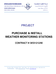
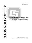
1
INSTRUCTION MANUAL
IPn3Gb
Cellular Modem
JBOVBSZ 201
Copyright © 2014
Campbell Scientific (Canada) Corp.
Table of Contents
PDF viewers: These page numbers refer to the printed version of this document. Use the
PDF reader bookmarks tab for links to specific sections.
1. Introduction ................................................................ 1
2. Cautionary Statements .............................................. 1
3. Initial Inspection ......................................................... 1
4. Specifications............................................................. 2
5. Installation .................................................................. 3
5.1
5.2
5.3
Base Station Requirements for IPn3Gb Cellular Modem .................... 4
Datalogger Site Equipment .................................................................. 4
Configuration ....................................................................................... 5
5.3.1 Support Materials .......................................................................... 5
5.3.2 Getting Started .............................................................................. 5
5.3.3 Connecting for Configuration ....................................................... 6
5.3.3.1 USB .................................................................................... 6
5.3.3.2 Ethernet .............................................................................. 6
5.3.4 Network Provisioning ................................................................... 7
5.3.4.1 Bell ..................................................................................... 7
5.3.4.1.1 Static IP ................................................................... 7
5.3.4.1.2 Dynamic IP .............................................................. 8
5.3.4.2 Telus ................................................................................... 8
5.3.4.2.1 Static IP ................................................................... 8
5.3.4.2.2 Dynamic IP .............................................................. 8
5.3.4.3 Rogers ................................................................................ 8
5.3.4.3.1 Dynamic IP .............................................................. 8
5.3.5 Dynamic DNS (DDNS) ................................................................ 9
5.3.5.1 DDNS Example ................................................................ 10
5.3.6 Serial Port Configuration (COM1/COM2) ................................. 12
5.3.7 Firewall ....................................................................................... 14
5.3.7.1 Firewall Rules (TCP Server) ............................................ 14
5.3.7.2 Port Forwarding (PPP and Ethernet Devices) .................. 15
5.3.8 Point to Point Protocol (PPP) Communications (optional) ......... 27
5.3.8.1 IPn3Gb COM1 PPP Configuration .................................. 28
5.3.8.2 IPn3Gb Firewall and Port Forwarding Configuration for PPP
...................................................................................... 29
5.3.8.3 Datalogger PPP Configuration ......................................... 32
5.3.9 Security ....................................................................................... 33
5.3.10 Configuration Backup ................................................................. 34
5.3.11 Load Configuration or Firmware ................................................ 35
5.4
LoggerNet Setup ................................................................................ 35
5.5
Wiring and Connections ..................................................................... 37
5.5.1 Modem Connection using the L18663 Null Modem Cable ........ 38
5.5.2 Modem Connection using the SC932A....................................... 38
5.5.3 Modem Connection using Ethernet ............................................. 38
5.6
Test the Cellular Connection .............................................................. 38
i
6. Operation .................................................................. 40
6.1
6.2
Program the Modem .......................................................................... 40
Connectors and Indicators ................................................................. 40
6.2.1 Modem Front.............................................................................. 40
6.2.2 Modem Back .............................................................................. 41
6.3
Hardware ........................................................................................... 42
7. Troubleshooting ....................................................... 44
Figures
Figure 5—1 Port Forwarding Fields ............................................................. 16
Figure 5—2 SC932A Interface ..................................................................... 38
Figure 6—1 Front view of the IPn3Gb Cellular Modem .............................. 40
Figure 6—2 Rear view of the IPn3Gb Cellular Modem ............................... 41
Figure 6—3 Antennas for use with the IPn3Gb Cellular Modem ................. 43
Tables
Table 5-1. Modem Connection to Datalogger .............................................. 37
ii
IPn3Gb Cellular Modem
1.
Introduction
This manual provides information for interfacing the Microhard IPn3Gb
cellular modem to Campbell Scientific dataloggers. Please note that this
manual will focus on the use of the IPn3Gb cellular modem on the Bell, Telus,
and Rogers networks.
The IPn3Gb cellular modem is a high-speed interface optimized for use on the
3G (HSPA+) network. The modem is accessed through the Internet using
TCP/IP communication protocols using a Public IP address (Dynamic or
Static).
The IPn3Gb cellular modem offers two-way communication between a
datalogger (and other devices such as the CC5MPX camera and any computer
with internet access).
2.
Cautionary Statements
x
x
x
3.
Although the IPn3Gb is designed to be a rugged and reliable device for
field use, care should be taken when handling or moving it to avoid
damage.
There are no user-serviceable parts and any attempt to disassemble the
device will void the warranty.
To avoid possible damage an antenna should be connected to the modem
prior to applying power.
Initial Inspection
x
Upon receipt of the IPn3Gb cellular modem, inspect the packaging
and contents for damage. File any damage claims with the shipping
company. Immediately check package contents against the shipping
documentation. Contact Campbell Scientific about any discrepancies.
x
The IPn3Gb is shipped with a L8125 (2.5 mm flat-blade)
screwdriver.
1
4.
Specifications
Supported bands:
UMTS/HSPA FDD Bands [MHz] – Six
band
Band I (2100MHz), Band II (1900MHz),
Band IV (1700MHz), Band V (850 MHz),
Band VI (800MHz), Band VII (900MHz)
3GPP Release 7
5.76 Mb/s uplink, 21.1 Mb/s downlink, or
5.76 Mb/s uplink, 7.2 Mb/s downlink
Data features:
HSDPA cat 14, up to 21.1 Mb/s DL for
LISA-U230
GPRS multi-slot class 125, coding
scheme CS1-CS4, up to 85.6 kb/s DL/UL
EDGE multi-slot class 125, coding
scheme MCS1-MCS9, up to 236.8 kb/s
DL/UL
CSD GSM max 9.6 kb/s
UMTS max 64 kb/s
TX Power:
WCDMA/HSDPA/HSUPA Power Class
x Power Class 3 (24 dBm) for
WCDMA/HSDPA/HSUPA
mode
GSM/GPRS Power Class
x Power Class 4 (33 dBm) for
GSM/E-GSM bands
x Power Class 1 (30 dBm) for
DCS/PCS bands
Edge Power Class
x Power Class E2 (27 dBm) for
GSM/E-GSM bands
x Power Class E2 (26 dBm) for
DCS/PCS bands
Current Consumption at 12vdc: Idle Current:
Without Ethernet Device: 70mA
With Ethernet Device: 85mA
UMTS Active Connection Current:
Average Serial Data: 75mA
Average Ethernet: 94mA
Peak Tx: 275mA
Serial Interface:
RS-232, RS-485, RS422
Serial Baud Rate:
300bps to 921kbps
USB:
USB 2.0, USB Console Port, USB to
Serial Data Routing, USB to Ethernet
Data Routing
2
5.
Ethernet:
10/100 BaseT, Auto – MDI/X, IEEE
802.3
SIM Card:
1.8 / 3.0V
PPP Characteristics:
Dial on Demand, Idle Time
Network Protocols:
TCP, UDP, TCP/IP, TFTP, ARP, ICMP,
DHCP, HTTP, HTTPS*, SSH*, SNMP,
FTP, DNS, Serial over IP, QoS
Management:
Local Serial Console, Telnet, WebUI,
SNMP, FTP & Wireless Upgrade,
RADIUS authentication, IPsec VLAN
Diagnostics:
Temperature, RSSI, remote diagnostics
Input Voltage:
7 to 30 Vdc
Operating Temperature:
-40 to +85°C
Humidty:
5% to 95% non-condensing
Dimensions:
56mm x 97mm x 37mm
Weight:
Approximately 245 grams
Antenna(s):
Main TX/RX: SMA Female
Connectors:
Data: DE-9 Female
Ethernet: RJ-45
Installation
What you need:
x
Determine coverage at the site for your chosen service provider. Coverage
maps are available on each provider’s website. It is also possible to search
for “Canadian cellular tower maps” for information on tower locations and
possible coverage.
x
A Public IP (Dynamic or Static) subscription on the HSPA network.
Service providers tend to have different names or descriptions for these
service add-ons. Below are key terms for each service provider:
o
Bell
Public Dynamic IP access
Public Static IP access
o
Telus
Dynamic Connect (Public)
Static Connect (Public)
3
NOTE
o
Rogers
Public Dynamic IP subscription
o
Data plan type: “Flex Data for Tablet” – (all 3 service
providers)
It is recommended to discuss the account types available and their
requirements with your intended Service Provider before
purchasing the IPn3Gb cellular modem.
What you receive from the service provider:
x
x
x
x
x
5.1
SIM card (standard size)
10-digit Cellular Telephone Number
Access Point Name (APN)
User name
Network Password for use with User Name (optional based on
configuration)
Base Station Requirements for IPn3Gb Cellular Modem
A PC running Campbell Scientific’s Loggernet or PC400 software, with access
to the Internet.
5.2
Datalogger Site Equipment
x
IPn3Gb cellular modem
x
Power Cable - FIN2PWR
x
Antenna - The antenna chosen for use in your application must be
connected to the “Antenna” connector of the IPn3Gb cellular modem. Do
not connect the antenna to the Rx Diversity connector.
x
Datalogger – CR1000, CR3000, CR800 series, CR200X series, and
CR10X.
x
L18663 Null Modem Cable – required if connecting the modem to the RS232 port of a CR1000, CR3000, CR800 series, or CR200X series
dataloggers
x
L28900 Ethernet Cable – connect the modem Ethernet port to a PC or
other Ethernet device. Commonly used to configure the modem. The
IPn3Gb Ethernet port is auto-sensing so a cross-over cable can also be
used. (optional)
x
C2809 USB Cable – connect the modem USB port to a PC in order to
configure the modem. (optional)
x
C2675 IPn3Gb Mount Kit – Used to mount the modem in the datalogger
enclosure with the use of DIN rail and DIN rail adaptors.
4
x
NOTE
5.3
SC932A Interface – required if connecting the modem to the CS I/O port
of a datalogger.
If you have a black SC12 cable that is not Rev1 or newer (indicated on cable), it
is a CS I/O cable and will not work for RS-232. Connect the black SC12 cable
between the datalogger and the SC932A. Use a 9pin serial cable or a blue ribbon
cable between the modem and the SC932A
Configuration
5.3.1 Support Materials
Supporting documentation is available for download from the Campbell
Scientific (Canada) website. If you are configuring the modem via a USB
connection, download and install the USB driver prior to connecting the
modem to your computer:
http://www.campbellsci.ca/19_1_1019
5.3.2 Getting Started
1.
SIM card – insert the card in the correct orientation into the slot located on
the front of the modem. You will know the card is properly installed when
you hear the card click into place.
2.
Antenna – connect the antenna to the “antenna” jack on the back of the
modem. This should be done prior to applying power.
5
3.
Connect the power cable between the Vin & GND terminals on the
modem and the power source.
4.
Connect the USB (C2809), Ethernet (L28900) or equivalent Ethernet cable
between the modem and the PC to start the configuration process.
5.3.3 Connecting for Configuration
Note
Be sure to allow the modem to warm up before trying to connect.
A minimum warm up time of 2 minutes is recommended.
In order to configure the modem you will need to connect via USB or Ethernet
using a web browser (e.g. Internet Explorer).
5.3.3.1 USB
Note
Requires the use of related USB driver and cable.
x
Enter the following IP address into the navigation bar of the web browser:
192.168.111.1
x
Enter User ID and Password
admin/admin
x
Enter the following IP address into the navigation bar of the web browser:
192.168.0.1
x
Enter User ID and Password
admin/admin
5.3.3.2 Ethernet
6
5.3.4 Network Provisioning
NOTE
The network provision configurations are specific to the service provider. The
remaining configuration steps are the same for Bell, Telus, or Rogers users.
Details related to Dynamic and Static IP configurations are listed below.
To provision the modem on the service provider network the following
information will need to be entered into the “Config” tab under “Carrier”.
Please note that the guidelines below may not apply in all cases. If you
encounter issues provisioning using the recommendations below, please
contact your service provider for the APN, User Name, and password
requirements for your specific SIM card. Please contact your service provider
for details related to the required APN for dynamic IP accounts.
It is possible to use a Public Static IP with the modem. For static IP accounts,
enter the static IP in “Static IP Addr”. Please contact your service provider for
details related to the required APN for static IP accounts.
5.3.4.1 Bell
5.3.4.1.1 Static IP
x
Access Point Name (APN): For example, static.bell.ca
Static APNs differ across Canada; ask Bell service provider for
appropriate APN
7
x
User Name: 10-digit phone#@static.bell.ca
x
Password: required; ask Bell service provider
x
Submit. (Save)
5.3.4.1.2 Dynamic IP
x
Access Point Name (APN): public.bell.ca
Across Canada, the APN for a Dynamic IP is public.bell.ca
x
User Name: 10-digit phone#@public.bell.ca
x
Password: not required
x
Submit. (Save)
x
APN: For example, static.telus.com
Static APNs differ across Canada; ask Telus service provider for
appropriate APN
x
User Name: 10-digit phone#@static.telus.com
x
Password: required; ask Telus service provider
x
Submit. (Save)
5.3.4.2 Telus
5.3.4.2.1 Static IP
5.3.4.2.2 Dynamic IP
x
Access Point Name (APN): connect.telus.com
Across Canada, the APN for a Dynamic IP is connect.telus.com
x
User Name: 10-digit phone#@connect.telus.com
x
Password: not required
x
Submit. (Save)
5.3.4.3 Rogers
5.3.4.3.1 Dynamic IP
x
APN: vpn.com or internet.com
x
User Name: wapuser1
x
Password: wap
8
x
Submit. (Save)
When provision details are saved to the modem, it should provision on the
network. This can be confirmed under System | Summary.
x
x
x
Active Status = Call in progress or Connected
Network = Name of service provider
SIM Card = Ready
Check RSSI value for signal strength. Signal strength should be greater than105dBm; the preferred signal strength is greater than -95.
5.3.5 Dynamic DNS (DDNS)
NOTE
If your modem is configured with a Static IP, skip this step and move on to
Section 5.3.6. If your modem is configured with a Dynamic IP, complete this
step.
In order to complete this step of the configuration, you must sign-up online for
a Dynamic Domain Name System (DDNS) service. Free services are
available, but depending on your application or network size a paid service
may be recommended. An example of how to setup a DDNS service is shown
in Section 5.3.5.1.
Once a DDNS account has been created, proceed with the DDNS
configuration.
x
Navigate to the “Config” tab under “Carrier”
x
Select “DDNS Config” to expand this configuration option
9
x
Choose from one of the following providers:
x
Enable “DDNS Status”
x
Select “Service name” of the provider you have signed up with. Enter
related domain, User ID, and Password
x
Submit
5.3.5.1 DDNS Example
The following is an example of how to setup a free DDNS service. The steps
listed are specific to this DDNS provider and may not reflect the steps required
to setup a DDNS from a different provider.
x
Of the available DDNS service providers select the one that best
meets your needs. Create an account and login.
10
x
Select the DNS manager link
x
Add an appropriate domain name and choose a suffix from the drop
down list.
x
Click “Add Domain”. If the combination is available the domain will
be added to your account. If the domain is not available select again
until you find a domain.
11
x
Be sure to have the domain, account username, and password details
available so that they can be entered into the modem configuration, as
well as the LoggerNet setup.
x
Enter details into the modem configuration
5.3.6 Serial Port Configuration (COM1/COM2)
In order for the modem to communicate with a Campbell Scientific datalogger,
the modem’s serial port must be properly configured. The IPn3Gb has two 9pin serial ports. The COM1 (Data) port can be used for either a TCP server or
PPP configuration. The COM2 (Diagnostic) port can only be used for TCP
server configuration. When required, both ports can be used simultaneously to
provide access to two dataloggers or other serial devices.
A PPP configuration is recommended for CR800 series, CR1000, or CR3000
dataloggers, as it allows access to the connected datalogger’s IP functionality
12
(e.g. FTP client, Email client, HTTP server, and FTP server). For information
on the PPP configuration procedure, see Section 5.3.8. However, a TCP server
configuration is also possible for use with these dataloggers if IP functionality
is not required.
For any datalogger without an IP stack (e.g. CR200X series or legacy
dataloggers), a TCP server configuration is the only option.
The settings below are applicable to the TCP server configuration. Parameters
which are not specified below, should be left at the default settings.
Under COM1 navigate to the ‘Config’ tab.
NOTE
x
Data Baud Rate = 115200 for use with a CR800 series, CR1000, or
CR3000 datalogger (or 9600 for use with a CR200X series or legacy
datalogger)
x
Character Timeout = 50
x
No-Connection Data Intake = Disable
x
Protocol config = TCP server
x
Local listening port = 6785 (default datalogger PakBus/TCP Service
port)
In order to avoid confusion or unwanted communication, it is recommended to
change this port to match the last 4 digits of the modem’s cellular telephone
number. This must be done in the modem (COM1 & Firewall), the datalogger,
and LoggerNet.
x
Submit (Save)
13
5.3.7 Firewall
The firewall controls the incoming and outgoing traffic through the modem
based on user-created rules. You must configure the firewall in order to
communicate with the datalogger. In addition, the firewall helps prevent
unauthorized access or data usage. The setup below can be used with all
service providers.
5.3.7.1 Firewall Rules (TCP Server)
This setup can be used with all service providers. The following assumes a RS232 or CS I/O connection to modem ‘Data’ port, when using the modem’s TCP
serial server mode.
x
Set Firewall Status is set to ‘Enable’. This must be enabled in order to
proceed with the remaining configuration.
x
Set WAN request to ‘Block’
x
Click the ‘Apply’ button
14
With the Firewall enabled it is possible to define specific traffic that will be
allowed by configuring the destination port, as described in the following steps.
x
Navigate to the ‘Rules’ tab
x
Enter a name for the rule
x
Configure the ‘Destination PORT’ to match that of the datalogger
(i.e. 6785). This must be the same as the PakBus port and the local
listening port configured in Section 5.3.6.
x
Click the‘Add’ button, then click the‘Apply’ button.
5.3.7.2 Port Forwarding (PPP and Ethernet Devices)
If you are using the modem’s serial PPP mode or are connecting to an Ethernet
device (e.g. CC5MPX), Port forwarding rules specifying how to direct
incoming traffic to the device must be created. In the case where there are
multiple devices, or only specific ports need to be passed, port forwarding is
used to forward traffic coming in from the Wide Area Network (WAN) to
specific IP Addresses and ports on the Local Area Network (LAN). The
IPn3Gb looks at each incoming Ethernet packet on the WAN and by using the
destination port number, determines where it will send the data on the private
LAN.
The fields required to configure port forwarding are found on the Port
Forwarding tab under the Firewall tab of the IPn3Gb user interface (see Figure
5-1 – Port Forwarding Fields). In order to implement a port forwarding rule,
enter the required values, click the Add button then the Apply button. Port
forwarding can be used in combination with other firewall features, but the
firewall must be enabled for port forwarding to be in effect.
15
Figure 5—1 Port Forwarding Fields
Rule Name - Enter a convenient reference or description for the rule. Each rule
must have a unique name, which can be up to 10 characters.
Internal Server IP - Enter the IP address of the intended internal server (i.e.
on LAN side of IPn3Gb). This is the IP address given to the device connected
to the IPn3Gb Ethernet port. The IP address must be based on the default IP
gateway and IP subnet mask of the IPn3Gb, which can be reviewed under the
Network > Config tabs.
Internal Port - Target port number of internal server on the private LAN IP
entered above.
Protocol - Select the type of transport protocol used. Although there are
several options, TCP should be the most common protocol in port forwarding
applications.
External Port - Port number of incoming requests (from public WAN side).
Considerations:
x
x
x
x
Ensure you have version 2.08 or greater of the Device Configuration
Utility software to be able to connect and configure individual
application components. Available for download at
https://www.campbellsci.ca/downloads?sb=dev&c=9999
The related USB cable for the devices and related drivers must be
installed. The drivers can be found for each device in the Device
Configuration Utility software under the given device.
The IPn3Gb should be active on an account with a service provider.
You will need to be able to configure the IPn3Gb.
Example of Port Forwarding using the IPn3Gb
Example 1:
In the example highlighted below we have configured the IPn3Gb and all
related equipment to allow for the simultaneous connection of 2 dataloggers to
the modem. The first datalogger, a CR200X, is connected directly to the data
16
port of the modem via a null modem cable. The second datalogger, a CR1000
is networked to the modem via an NL201 and a pair of RF401A radios.
In any such arrangement it is important to configure firewall and port
forwarding rules to ensure proper access while maintaining a reasonable level
of protection.
This example assumes that all necessary configuration steps were taken to
provision the IPn3Gb on the network in either a Static or Dynamic IP
arrangement.
Following is a diagram of the physical connection of the applications:
17
CR200X portion of the application:
In this example, the CR200X is left in its default state.
1. IPn3Gb COM1 configuration
a.
Change the COM1 Data Baud Rate to 9600 to match the CR200X default
baud rate.
b. Confirm that the Local Listening Port is 6785 (default port of the
CR200X).
c.
Submit new settings.
18
2. Activate Firewall
a. Set the firewall status to Enable. This is required for the operation of the
Firewall and port forwarding rules.
3. Firewall Rule for the CR200X in the IPn3Gb (same as Section 5.3.7)
a. Configure a rule that will allow WAN IP traffic through the firewall on
port 6785. This allows remote access to the CR200X, which has a default port
of 6785.
b.
Add the new rule and Apply.
19
4. Loggernet setup for CR200X remote communications
a. Add an IP port – enter the Static IP or Dynamic DNS details for the
IPn3Gb cellular modem, followed by port 6785.
b. Add a PakBus port and a CR200 series datalogger. In this example, the 2
elements of the Loggernet setup stay in their default state.
c.
Apply setup.
20
CR1000 portion of the application:
1. Port Forwarding Rule for the NL201 in the IPn3Gb Cellular Modem
a.
Give the port forwarding rule a name.
b. Set the Internal Server IP to 192.168.0.2. The use of this IP address is
based on the IPn3Gb having a gateway of 192.168.0.1. and an IP subnet mask
of 255.255.255.0. These variables can be changed in the IPn3Gb setup under
Network/Config, if required.
c.
Set the internal and external ports to 6784.
d.
Add the new rule and Apply.
21
2. NL201 Setup – Network Settings
a.
Disable ‘Use DHCP’
b. Enter the IP address, network mask, and default gateway, as required. In
this example, the NL201 is given the IP address 192.168.0.2, with a network
mask of 255.255.255.0, and a default gateway of 192.168.0.1.
22
3. NL201 Setup – RS-232 settings
a.
Set the configuration to TCP Serial Server.
b.
If you require the use of a port other than 6784, change the service port.
c. Set the baud rate to 38400. This will match the default baud rate used in
the RF401A.
d.
Apply the configuration to save the settings on both tabs.
23
4. RF401A spread spectrum radio – base (at NL201)
a.
Set the active interface to RS-232
b.
Set the protocol to Transparent
c.
Apply the configuration
24
5. RF401A spread spectrum radio – Remote (at CR1000)
In this example, the radio is using the CSI/O port to connect to the datalogger.
The RS-232 port can be used, if required. If the RS-232 is required, a
configuration
a.
Set the active interface to RS-232
b.
Set the protocol to Transparent
c.
Apply the configuration
25
6. Loggernet setup for CR1000 remote communications
a.
Add an IP port – enter the static IP or the dynamic DNS details for the
IPn3Gb cellular modem, followed by port 6784.
b. Add a PakBus port and a CR1000 series. In this example, the 2 elements
of the LoggerNet setup stay in their default states.
c.
Apply setup.
26
5.3.8 Point to Point Protocol (PPP) Communications (optional)
Note
The firmware version of the IPn3Gb must be v2.2.0-r2130 or
newer to be able to properly work with the datalogger using the
PPP connection. If required, an update is available from the
Campbell
Scientific
(Canada)
website
at:
http://www.campbellsci.ca/19_1_768
In PPP mode, the modem assigns the datalogger an IP address by means of a
serial connection. This allows access to the datalogger’s IP capabilities without
requiring an Ethernet peripheral. The modem’s COM1/Data port must be used
for a PPP connection. In order for the PPP to function properly, both the
modem and datalogger need to be configured as described in Sections 5.3.8.1
through 5.3.8.3, which highlight a standard configuration. The physical
27
connection for PPP communications requires the use of a null modem cable to
connect the datalogger RS-232 to the modem ‘Data’ port.
5.3.8.1 IPn3Gb COM1 PPP Configuration
It is necessary to configure COM1 to use PPP so that the datalogger can
communicate with a network using a PPP connection. Other PPP settings can
be adjusted as needed, but any changes must be reflected appropriately in the
modem and datalogger configuration.
x
x
x
x
x
x
x
x
x
Under COM1, navigate to the ‘Config’ tab
Data Baud Rate = 115200
Character Timeout = 50
Protocol config = select ‘PPP’
Expected String = delete ‘CLIENT’ and leave field blank
Response String = ‘CONNECT’ (Entry must be all upper case)
PPP Local IP = 192.168.0.1 (This is the default local IP of the
modem)
PPP Host IP = 192.168.0.99 (This is the IP address that will be
assigned to the datalogger)
Submit (Save)
The following parameters need to be setup the same in both the modem and
datalogger:
x
x
x
Baud rate
Data format
Handshaking
28
5.3.8.2 IPn3Gb Firewall and Port Forwarding Configuration for PPP
The proper configuration of the Firewall and the related Port Forwarding Rules
is necessary to control different types of access and ensure that IP traffic is
properly routed through the modem to the datalogger. The configuration of the
Firewall will help avoid unauthorized access to data usage.
x
x
x
Ensure Firewall status is set to ‘Enable,’ in order to proceed with the
remaining configuration.
Set WAN request to ‘Block.’
Click ‘Apply’
29
Under the Firewall tab, select Port Forwarding. Rules are required to map the
ports required to ensure HTTP, FTP and LoggerNet communications to the
datalogger at the assigned IP address.
1. In order to setup access to the datalogger HTTP server (for access to the
datalogger’s webpage), the following rule configuration needs to be added and
applied:
x
x
x
x
x
x
Enter a Rule Name for HTTP
Internal Server IP = 192.168.0.99 (this is the IP address assigned to
the datalogger)
Internal Port = 80
Protocol = TCP
External Port = 8000
Click ‘Add’ button, then ‘Apply’
The external port number 8000 is an example. Use any
(unrestricted) port number other than 80, 443, or 23, as they are
required for modem access and configuration. Be sure to include
the external HTTP port number in any communications attempting
to reach the datalogger webpage (ex.: 173.182.77.117:8000).
Note
2. In order to setup access to the datalogger’s FTP server (for remote file
access), the following rule configuration needs to be added and applied:
x
x
x
x
x
x
NOTE
Enter a Rule Name for FTP
Internal Server IP = 192.168.0.99 (this is the IP address assigned to
the datalogger)
Internal Port = 21
Protocol = TCP
External Port = 2100
Click ‘Add’, then ‘Apply’
The external port number 2100 is used as an example. Use any (unrestricted)
port number other than 80, 443, or 23, as they are required for modem access
and configuration. Be sure to include the external FTP port number in any
communications attempting to reach the datalogger FTP site (ex.:
ftp://173.182.77.117:2100).
30
3. In order to setup access to the datalogger via LoggerNet and the
PakBus/TCP Service Port, the following rule configuration needs to be added
and applied:
x
x
x
x
x
x
NOTE
Enter a Rule Name
Internal Server IP = 192.168.0.99 (this is the IP address assigned to
the datalogger)
Internal Port = 6785
Protocol = TCP
External Port = 6785
Click ‘Add’, then ‘Apply’
Be sure to include the external port number in any communications attempting
to reach the datalogger (ex.:173.182.77.117:6785).
31
5.3.8.3 Datalogger PPP Configuration
Using the Device Configuration Utility, connect to the datalogger to configure
the PPP and ComPorts settings.
Under the ComPorts Settings tab:
x
x
Select the RS-232 ComPort
Baud Rate = 115.2K Fixed (baud rate must be fixed and match the
baud rate set in the modem under COM1)
Under the PPP settings tab:
x
x
x
Config/Port Used = RS-232
Modem Dial String = PPP (Entry must be in all upper case)
Click ‘Apply’
32
5.3.9 Security
Note
If either password is lost the modem will need to be manually reset
to defaults and reconfigured in order to regain access.
In order to keep the system secure it is recommended to change the
administrator and upgrade passwords from the factory defaults. Changing the
administrator password will protect against modifications to the modem’s
configuration. Changing the upgrade password will protect against
unauthorized upgrades.
x
Under Security navigate to the Password tab
x
Change passwords as needed. Be sure to maintain a sercure record so
that a reference is available.
x
Submit
33
5.3.10 Configuration Backup
It is possible to backup the configuration of a modem after completion.
x
Under Tools navigate to the Maintenance tab.
x
Select “Download” under System Settings. This will allow a text file
to be downloaded to a PC.
x
Save the “system.config” file as required.
34
5.3.11 Load Configuration or Firmware
It is possible to upload a “system.config” file to a modem either to restore
settings or as a template to help configure multiple modems.
Note
5.4
x
Under Tools navigate to the Maintenance tab.
x
Under HTTP Upgrade: ‘File:’ browse for the related file.
x
Open the “system.config” and upload the file. It must be loaded as
“system config” regardless of the filename it was saved under.
The modem will only accept the filename “system.config”
otherwise you will receive an error message.
LoggerNet Setup
The Loggernet “Device Map” is configured from the “Setup” button on the
LoggerNet Toolbar. From the Loggernet Toolbar, click Main | Setup, and
configure the Device Map as described below.
Note
The process is the same for Bell, Telus, or Rogers users
1. Select Add Root | IPPort
2. Add a datalogger to the IPPort PakBus datalogger; e.g., the CR1000,
requires a PakBusPort as well.
3. On the IP Port setup:
a.
Add the Domain Name (see Section 5.3.5) or IP address of the modem
to the Internet IP Address field, followed by the Port number. This
number (6785) is the datalogger’s default port number. It is also used
to configure the “COM1” and “Firewall” settings of the IPn3Gb
cellular modem. Whenever possible it is recommended to change this
number to the last four digits of the related cellphone number.
b.
Extra response time should be 10 - 12 seconds.
c.
Click “Apply”.
35
4. For PakBus dataloggers, add 10 seconds of Extra Response Time.
“PakBus Port Always Open” should not be checked.
36
5.
5.5
For PakBus dataloggers, set the PakBus address to match that of the
datalogger (default address in the datalogger is 1). Click the “Apply” button
to save changes.
Wiring and Connections
Power for the modem can be sourced directly from the datalogger. Refer to
Table 5-1 for details. Connection to the switched 12V terminal allows the user
to control power to the modem through the datalogger program. In this way,
power can be conserved by limiting the time that the modem is on. For
example, the user could choose to power on the modem only for scheduled data
collections or only during certain hours of the day. When using the switched
12V terminal, be sure to allow time for the modem to warm up and provision to
the network. The required warm up time can vary, but the recommended
minimum is 2 min.
TABLE 5-1. Modem Connection to Datalogger
Colour
Function
Datalogger
Modem
Red
Power source
12V (or SW12V)
Vin+
Black
Ground
G
GND
37
5.5.1 Modem Connection using the L18663 Null Modem Cable
In order to connect to a CR1000, CR3000, CR800, or CR200X series RS-232
port you will require a Null Modem Cable, Campbell Scientific part number
L18663. Connect one end of the Null Modem Cable to the IPn3Gb cellular
modem and the other to the datalogger’s RS-232 port.
5.5.2 Modem Connection using the SC932A
If connecting to any datalogger’s CS I/O port you will require an SC932A
interface from Campbell Scientific. Connect the supplied black SC12 cable to
the datalogger side of the SC932A interface, and then to the CS I/O port of the
datalogger. Connect the DCE Device side of the SC932A interface to the
IPn3Gb cellular modem’s RS-232 port using the supplied straight through
serial cable L10873.
Figure 5—2 SC932A Interface
5.5.3 Modem Connection using Ethernet
In some cases it may be desirable to connect using the Ethernet interface
available on the IPn3Gb cellular modem. To do this, you will require a
CR1000 or CR3000 with either a NL120 Ethernet Interface, NL115
Ethernet/Compact Flash Module, or any datalogger using a NL2XX series
device. A crossover Ethernet cable is needed to connect the two devices.
Please review the literature for the specific interface for more details.
5.6
Test the Cellular Connection
After the Device Map has been configured, it is recommended to test the
cellular connection using the “Connect” screen, as shown below. Click on the
appropriate station, then click the “Connect” button to initiate a call to the
datalogger. Be sure all connections are complete and power is supplied to both
the modem and datalogger.
If the call is successful, the connectors at the bottom of the screen will come
together, and time information from the datalogger will be displayed the
“Station Date/Time” field. If the connection fails, a “Communications Failure”
message is displayed. Troubleshooting procedures can be found in Section 7
Troubleshooting.
38
39
6.
Operation
6.1
Program the Modem
It is recommended that the modem be provisioned and tested in the office
(assuming cellular coverage) rather than in the field.
6.2
Connectors and Indicators
6.2.1 Modem Front
The front of the IPn3Gb cellular modem includes the USB port, Diagnostic
port, SIM card slot, Indicator LEDs, and Config button.
Figure 6—1 Front view of the IPn3Gb Cellular Modem
x
The USB port can be used to configure the modem. See Section
5.3.3.1 for details.
x
Currently, the Diagnostic port is not used
x
The SIM Card Slot houses the SIM card required for proper operation.
The SIM card supplied by the service provider must be inserted into
the SIM card slot.
x
RF LED (Red) - When connected to a 2G/EDGE or 3G-WCDMA
Network, the RF LED indicates a transmission burst. When connected
to a 3G/HSPA Network the LED has no function.
x
SGNL LED (Green) - When illuminated, the SGNL LED indicates
that the modem is connected and synchronized with a wireless carrier.
x
Receive Signal Strength Indicator (RSSI) (3x Green) - As the received
signal strength increases, starting with the furthest left, the number of
active RSSI LEDs increases. If the measured signal strength is less
than –110dBm no LED’s will be illuminated. If the signal is greater
than –105dBm, 1 LED will be on, - 100dBm equals 2 LED’s, and any
signal greater than –95dBm will show all 3 RSSI LED’s to be ON.
x
STATUS LED (Red) - Upon initial application of power the STATUS
LED will be illuminated for approximately 20 seconds, after which, it
will being to blink slowly (loading) for an additional 25 seconds, then
40
stay ON solid (indicating it has achieved its specific operational
status).
x
CONFIG (Button) - Holding this button depressed while powering-up
the IPn3G will boot the unit into FLASH FILE SYSTEM
RECOVERY mode. The default IP address for system recovery (only
- not for normal access to the unit) is static: 192.168.1.39.
x
If the unit has been powered-up for some time (>1 minute), depressing
the CFG Button for 8 seconds will result in FACTORY DEFAULTS
being restored, including a static IP address of 192.168.0.1. This IP
address is useable in a Web Browser for accessing the Web User
Interface.
6.2.2 Modem Back
The back of the modem includes the Antenna SMA(F) connector, power
connection, Data (RS-232) port, and Ethernet port
Figure 6—2 Rear view of the IPn3Gb Cellular Modem
x
The Antenna required for the application is connected to the Antenna
connector. The GPS and RX DIV are not used.
x
The Green connector plug included with the modem is used to make
the power connection. Connections and use of the RS485/422 are not
referenced in this manual.
x
The DATA port is used to connect to a datalogger’s RS-232 or CS I/O
port.
x
The Ethernet port can be used to configure the modem. See Section
5.3.3.2 for details. The Ethernet port can also be used to communicate
with a datalogger and compatible interface using a compatible
network link interface (see Section 5.5.3).
41
6.3
Hardware
x
C2675 IPn3Gb Mounting Kit – includes mounting hardware for
securing the modem to below referenced environmental enclosure.
IPn3Gb should be mounted in a position that allows easy access for
the cables so they are not bent, or constricted.
x
Antenna – the following antennas are available from Campbell
Scientific. The antenna must be connected to the “Antenna”
connector of the IPn3Gb cellular modem. Contact a Campbell
Scientific Applications Technician for help in determining the best
antenna for your application.
o
The C2446 is a dual-band, 3dB omni-directional antenna for our
CDMA and GPRS digital-cellular modems. This antenna is
recommended for locations where cellular coverage is strong.
The C2446 includes a mount/u-bolt assembly that allows the
antenna to be mounted to a mast, crossarm, or user-supplied pole
(outer diameter of up to 1.5" (3.8 cm)).
o
The C2445 9dBd Yagi Antenna is a higher gain antenna that
should be "aimed" at the service provider's antenna. The C2445
is a 800 MHz antenna and bracket/u-bolt assembly for attaching
the antenna to a mast or post. The antenna comes with 10’ of
cable. This antenna is recommended for fringe areas that require
a higher gain antenna.
o
The C2444 9dBd Yagi Antenna is a higher gain antenna that
should be "aimed" at the service provider's antenna. The C2444
is a 800 MHz antenna and bracket/u-bolt assembly for attaching
the antenna to a mast or post. The antenna comes with 30’ of
cable and surge protection. This antenna is recommended for
fringe areas that require a higher gain antenna.
o
The L18285 is a dual-band 1 dBd omni-directional antenna. The
antenna covers both the 800 MHz and 1.9 GHz bands, and is
strongly recommended where cellular coverage is strong. The
L18285 includes a mount/u-bolt assembly for attaching the
antenna to a mast, post, or crossarm up to 1.5" (3.8 cm) in
diameter.
o
The L21831 Half-Wave Dipole Whip Antenna is a lower gain
antenna used in transmitting short distances. It is an 800 MHz
cellular antenna that terminates in a SMA Male connector for
attachment to the modem. This antenna is intended for use inside
the enclosure. Please note that the backplate of the enclosure is a
grounded plane. If it is interposed between the antenna and the
cell tower, it may attenuate the strength of the transmission
signal. Simply turning the enclosure 90 to 180° on its mounting
mast may solve weak transmission issues.
42
L18285 1 dBd Omni Directional Antenna
C2444/C2445 9dBd Directional Yagi Antenna
L21831 Half-Wave Dipole Whip Antenna
Figure 6—3 Antennas for use with the IPn3Gb Cellular Modem
x
Power Supply (See Section 6.5 Wiring and Connections).
x
Environmental Enclosure— ENC 10/12, ENC 12/14, or ENC 16/18.
43
7.
Troubleshooting
If LoggerNet/PC400W software is unable to establish a connection with the
modem:
1.
Check your account information (you may have to call your provider for
this or look at your agreement).
2.
Verify there is coverage at your location.
3.
Check the RF and SGNL Indicator LEDs on the front of the modem.
Ensure that the modem has successfully connected to the cellular network.
4.
Make sure the modem and datalogger have sufficient power.
5.
Check the RSSI LEDs on the front of the modem or in the Web Interface.
If the measured signal strength is less than –110dBm no LED’s will be
illuminated. If the signal is greater than –105dBm, 1 LED will be on, 100dBm equals 2 LED’s, and any signal greater than –95dBm will show
all 3 RSSI LED’s to be ON.
6.
If you have a Dynamic IP account, you will need to have a dynamic
domain name server (DDNS) name that LoggerNet can reference to make
the connection. Refer to Section 5.3.5 for details.
7.
In the “Summary” tab in the “System” group of the modem’s
configuration webpage, make sure Activity Status is “Call in Progress” or
“Connected”, and note the WAN IP Address. This is the current IP
address for the modem (a dynamic IP address will change each time the
modem is reset). Try connecting to this IP address using LoggerNet. If
LoggerNet connects with the IP address, but not with the modem
name.domain name, then there may be a problem with the Dynamic IP
setup in the modem.
44
Campbell Scientific (Canada) Corp. | 14532 131 Avenue NW | Edmonton AB T5L 4X4 | 780.454.2505 | www.campbellsci.ca
AUSTRALIA | BRAZIL | CANADA | COSTA RICA | FRANCE | GERMANY | SOUTH AFRICA | SPAIN | UNITED KINGDOM | USA