1
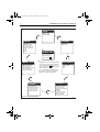
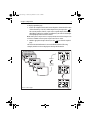
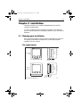
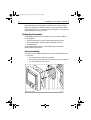
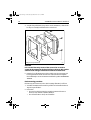
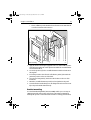
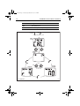
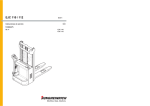
81039_4.book Page i Wednesday, March 24, 2004 3:14 PM
ST60 Multi
Instrument
Owner’s
Handbook
Document number: 81039-4
Date: 1 April 2004
81039_4.book Page ii Wednesday, March 24, 2004 3:14 PM
Raymarine, ST60 and SeaTalk are trademarks of Raymarine Limited
© Handbook contents copyright Raymarine Limited 2004
81039_4.book Page i Wednesday, March 24, 2004 3:14 PM
Preface
i
Preface
Important information
Safety notices
WARNING: Product installation & operation
This equipment must be installed and operated in accordance
with the Raymarine instructions provided. Failure to do so could
result in personal injury, damage to your boat and/or poor product
performance.
WARNING: Electrical safety
Make sure you have switched off the power supply before you
start installing this product.
WARNING:
Although we have designed this product to be accurate and
reliable, many factors can affect its performance. Therefore, it
should serve only as an aid to navigation and should never replace
commonsense and navigational judgement. Always maintain a
permanent watch so you can respond to situations as they
develop.
EMC conformance
All Raymarine equipment and accessories are designed to the best industry
standards for use in the recreational marine environment.
The design and manufacture of Raymarine equipment and accessories conform to
the appropriate Electromagnetic Compatibility (EMC) standards, but correct
installation is required to ensure that performance is not compromised.
Handbook information
To the best of our knowledge, the information in this handbook was correct when
it went to press. However, Raymarine cannot accept liability for any inaccuracies
or omissions it may contain.
In addition, our policy of continuous product improvement may change
specifications without notice. Therefore, Raymarine cannot accept liability for any
differences between the product and the handbook.
81039_4.book Page ii Wednesday, March 24, 2004 3:14 PM
ii
ST60 Multi Instrument Owner’s Handbook
81039_4.book Page iii Wednesday, March 24, 2004 3:14 PM
Preface
iii
Contents
Preface ......................................................................................................................i
Important information ..................................................................................... i
Safety notices .......................................................................................... i
EMC conformance ................................................................................... i
Handbook information ............................................................................ i
Contents................................................................................................... iii
Introduction ...................................................................................................vii
Data inputs ....................................................................................................vii
Remote control .............................................................................................viii
Options .........................................................................................................viii
Auxiliary alarm .....................................................................................viii
Mounting options ................................................................................viii
Parts supplied ...............................................................................................viii
Chapter 1: Operation ............................................................................................1
1.1 Introduction ........................................................................................... 1
1.2 Normal operation ................................................................................... 1
Finding the information you want .......................................................... 1
1.3 Chapters and pages ............................................................................... 4
Depth chapter pages .............................................................................. 4
Speed chapter pages .............................................................................. 4
Wind chapter pages ............................................................................... 5
Heading chapter pages .......................................................................... 5
Navigate chapter pages ......................................................................... 6
Environment chapter pages ................................................................... 6
Autopilot chapter pages ......................................................................... 7
1.4 Using the track key ................................................................................. 7
1.5 Alarms .................................................................................................... 7
Internal alarms ....................................................................................... 7
Auxiliary Alarm option ........................................................................... 8
1.6 Operating with NMEA ............................................................................ 8
SeaTalk to NMEA 0183 ........................................................................... 8
NMEA to SeaTalk .................................................................................... 9
1.7 Display settings ...................................................................................... 9
Illumination ............................................................................................ 9
Contrast ............................................................................................... 10
1.8 Pop-up Pilot .......................................................................................... 10
1.9 Remote control .................................................................................... 10
81039_4.book Page iv Wednesday, March 24, 2004 3:14 PM
iv
ST60 Multi Instrument Owner’s Handbook
Chapter 2: Maintenance & Troubleshooting ..................................................11
2.1 Maintenance ........................................................................................11
Servicing and safety ..............................................................................11
Instrument ............................................................................................11
Transducer ............................................................................................11
Cabling .................................................................................................12
2.2 Troubleshooting ...................................................................................12
Preliminary procedures .........................................................................12
Fixing faults ..........................................................................................12
Technical support ..................................................................................13
World wide web .............................................................................13
Telephone help line ........................................................................13
Help us to help you .........................................................................13
Chapter 3: Installation .......................................................................................15
3.1 Planning your installation .....................................................................15
Site requirements .................................................................................15
EMC installation guidelines ..................................................................16
Suppression ferrites ........................................................................17
Connections to other equipment ....................................................17
3.2 Procedures ...........................................................................................17
Unpacking ............................................................................................17
Fitting the instrument ...........................................................................18
Surface mounting ...........................................................................18
Flush mounting ..............................................................................19
Fitting the low-profile bezel ......................................................19
Flush mounting procedure .......................................................20
Bracket mounting ...........................................................................21
Auxiliary alarm option ..........................................................................22
Connecting the instrument ...................................................................23
Types of connection ........................................................................23
Connection options ........................................................................23
Signal connections .........................................................................23
Power supply connections ..............................................................25
Chapter 4: Calibration ........................................................................................27
4.1 Introduction ..........................................................................................27
EMC conformance ................................................................................27
4.2 User calibration ....................................................................................27
Procedure .............................................................................................28
Chapter titles ..................................................................................28
Heading type ..................................................................................28
Battery alarm threshold ..................................................................28
Alarms on/off .................................................................................28
81039_4.book Page v Wednesday, March 24, 2004 3:14 PM
Preface
v
Date format .................................................................................... 28
Time format ................................................................................... 28
Time offset ..................................................................................... 30
Units setup ..................................................................................... 31
Setting units ............................................................................. 31
Waypoint identity ........................................................................... 31
Select NMEA or auxiliary alarm ...................................................... 31
Auxiliary alarm enable ................................................................... 31
Pop-up pilot ................................................................................... 32
Instrument configuration ............................................................... 32
Leaving User calibration ....................................................................... 34
4.3 Intermediate calibration ....................................................................... 34
4.4 Dealer calibration ................................................................................. 35
User calibration on/off ......................................................................... 35
Response settings ................................................................................ 35
Factory defaults .................................................................................... 37
Leaving Dealer calibration .................................................................... 37
81039_4.book Page vi Wednesday, March 24, 2004 3:14 PM
vi
ST60 Multi Instrument Owner’s Handbook
81039_4.book Page vii Wednesday, March 24, 2004 3:14 PM
Preface
vii
Introduction
Thank you for purchasing a Raymarine product. We are sure your ST60 instrument
will give you many years of trouble-free operation.
This handbook describes how to install and use the Raymarine ST60 Multi
instrument. This instrument provides a wide range of accurate depth information,
on a high quality Liquid Crystal Display (LCD). The instrument is constructed in a
rugged weather-proofed case to provide reliable performance, even under the
most demanding conditions.
23-2
D43
Data inputs
SeaTalk enables a number of compatible instruments to operate as a single,
integrated navigational system. Instruments in a SeaTalk system are linked by
means of a single cable, which feeds both power and data. Instruments can
therefore be added to the system by plugging them into the network. SeaTalk is
flexible enough to adapt to any number of compatible instruments without
requiring a central processor.
When connected to SeaTalk, the ST60 Multi instrument repeats information
provided by other equipment in the SeaTalk network.
The ST60 Multi instrument can also provide data communication between the
internationally-accepted National Marine Electronics Association (NMEA)
systems and SeaTalk.
81039_4.book Page viii Wednesday, March 24, 2004 3:14 PM
viii
ST60 Multi Instrument Owner’s Handbook
Remote control
When connected to SeaTalk, the ST60 Multi instrument can be controlled
remotely by a SeaTalk Remote Keypad Unit, to provide instant remote access to
the various display readouts.
Options
Auxiliary alarm
An Auxiliary Alarm (Raymarine Part No. Z035)can be connected to the ST60 Multi
instrument and set to respond to various system alarms. This provides an
additional audible alarm at a much higher volume than the internal alarm.
Mounting options
If you do not want to surface mount your ST60 instrument, options are available
for:
• Flush mounting. If you have ordered the flush mounting option a low-profile
bezel and four fixing screws are provided.
• Bracket mounting.
Parts supplied
Unpack your ST60 instrument and check that the following items are present:
• Item 1,ST60 Multi instrument fitted with standard bezel for surface mounting.
• Item 2,Fixing studs (2).
• Item 3,Thumb nuts (2).
• Item 4,Gasket.
• Item 5,SeaTalk interconnection cable.
• Item 6,Instrument Cover.
• Item 7,Owner’s Handbook. A Warranty document and fitting templates are
included in this Handbook.
• Item 8,Cue Card.
Spare spade terminals are also provided.
81039_4.book Page ix Wednesday, March 24, 2004 3:14 PM
Preface
ix
1
4
2
3
2
3
5
6
MULTI
ST60 Multi
Instrument
Owner's
Handbook
Operation
Key:
Chapter selection and content
7
8
D4440-3
81039_4.book Page x Wednesday, March 24, 2004 3:14 PM
x
ST60 Multi Instrument Owner’s Handbook
81039_4.book Page 1 Wednesday, March 24, 2004 3:14 PM
Chapter 1: Operation
1
Chapter 1: Operation
1.1 Introduction
This handbook describes how to operate, maintain and install the Raymarine
ST60 Multi instrument.
CAUTION: Calibration requirement
The ST60 Multi instrument is calibrated to factory (default)
settings when first supplied. To ensure optimum performance on
your boat, this product must be calibrated before use. Do NOT use
the product until it has been calibrated using the procedures in
Chapter 4, Calibration.
1.2 Normal operation
The information displayed on the ST60 Multi instrument is organized in groups or
‘chapters’, and within each chapter, the different types of information are
presented as pages. The availability of pages on your ST60 Multi instrument
depends on:
• What information is available from SeaTalk. This handbook assumes all data
sources are available.
• Which pages are enabled during Instrument configuration (see Chapter 4,
Calibration ). This handbook assumes all pages are enabled.
Finding the information you want
The disposition of the ST60 Multi chapters and pages, is shown in the Chapter
selection and content illustration, below. This illustration assumes a system
where all information sources are available.
81039_4.book Page 2 Wednesday, March 24, 2004 3:14 PM
2
ST60 Multi Instrument Owner’s Handbook
Depth
Current depth
Minimum depth
Maximum depth
Speed
Autopilot
Speed
Maximum speed
Average speed
Speed over ground
VMG to windward
Log
Trip
Timer
Pilot status
Rudder angle
Key:
Chapter name
Pages within chapter
Listed in sequence.
Accessed with
key.
Wind
Apparent wind speed
Apparent wind angle
True wind speed
True wind angle (sailing)
True wind direction
Beaufort and cardinal
Notes:
1. If chapter titles are enabled during calibration,
the name of the selected chapter is displayed
for 2 seconds after the
key is pressed,
after which time, the first page in the selected
chapter is displayed.
Environment
Water temperature
Battery voltage
Time
Date
2. You can switch off any unwanted chapter or
page, to reduce the amount of information
displayed (see Chapter 4, Calibration ).
Heading
Navigate
Navigate
Current heading
Locked heading
Heading on next track
Course over ground
Course made good
Distance made good
Bearing to waypoint
Distance to waypoint
Cross track error
Waypoint number/name
Latitude
Longitude
Course over ground
Speed over ground
Satellites tracked
Chapter selection and content
D4409-1
81039_4.book Page 3 Wednesday, March 24, 2004 3:14 PM
Chapter 1: Operation
3
To display a particular page:
1. Refer to the Chapter selection and content diagram to determine the location
of the information you need (i.e. which chapter it is in), then press the
key
the necessary number of times, to cycle to the required chapter. If the chapter
title facility is enabled (see Chapter 4, Calibration ), the name of each chapter
is briefly displayed when it is first selected.
Note: Although most chapter names are displayed in full, the Environment chapter is abbreviated to ENVIRO and the Autopilot chapter is abbreviated to PILOT .
2. With the appropriate chapter selected, use the
page.
key to select the required
The manner in which information is accessed is illustrated in the following
example, which shows how to display true wind speed information.
Selecting chapter
Selecting page
Either press
or wait for
2 second
time out
How to select a page
D4405_1
81039_4.book Page 4 Wednesday, March 24, 2004 3:14 PM
4
ST60 Multi Instrument Owner’s Handbook
1.3 Chapters and pages
This section lists all the available pages along with titles and salient points.
Depth chapter pages
Function
Title
Remarks
Current
depth
-
Displayed in either FEET , METRES or FATHOMS . An up arrow is displayed
if the sea-bed is rising, and a down arrow is displayed for sea-bed falling. If
the depth echo is lost, the last valid depth reading is shown and LAST flashes.
Minimum
depth
MIN
Minimum depth since power up or last reset, in feet (FT) meters (M) or fathoms (FA). Press the reset key for 3 seconds, to reset.
Maximum
depth
MAX
Maximum depth since power up or last reset, in feet (FT) meters (M) or fathoms (FA). Press the reset key for 3 seconds, to reset.
Speed chapter pages
Function
Title
Remarks
Boat speed
BOAT
Displayed in kilometers per hour (KMH), miles per hour (MPH), or knots (KTS).
Maximum
speed
MAX
Maximum speed since power up or last reset, in kilometers per hour (KMH),
miles per hour (MPH), or knots (KTS). Press the reset key for 3 seconds, to
reset.
Average
speed
AVG
Average speed since power up or last reset, in kilometers per hour (KMH),
miles per hour (MPH), or knots (KTS).
Speed over
ground
SOG
Displayed in kilometers per hour (KMH), miles per hour (MPH), or knots (KTS).
Velocity
made good
VMG
Displayed in kilometers per hour (KMH), miles per hour (MPH), or knots (KTS).
Log
LOG
Total distance covered since the system was installed, in kilometers (KM),
statute miles (SM), or nautical miles (NM).
Trip
TRIP
Distance covered since power up or last reset, in kilometers (KM), statute
miles (SM), or nautical miles (NM).
Count up
timer
TIMER Shows current count-up time in either seconds (S), minutes (M) or hours (H).
Count-down
timer
RACE Shows time remaining to zero in seconds (S) or minutes (M).
START
81039_4.book Page 5 Wednesday, March 24, 2004 3:14 PM
Chapter 1: Operation
5
Wind chapter pages
Function
Title
Remarks
Apparent
wind speed
APP
Either knots (KTS) or meters per second (M/S).
Apparent
wind angle
APP
Shown in degrees. Shows a STBD indicator when the boat is on a starboard tack and a PORT indicator when the boat is on a port tack.
True wind
speed
TRUE
Either knots (KTS) or meters per second (M/S).
True wind
angle
TRU
Shown in degrees. Shows a PORT indicator when the boat is on a starboard tack and a STBD indicator when the boat is on a port tack.
True wind
direction
WIND
Shown in degrees. Shows either a MAG(netic) or TRU(e) indicator,
depending on the selected bearing type.
Beaufort and
cardinal
BFT
Shows the wind speed Beaufort scale value and wind direction as a cardinal compass point.
Heading chapter pages
Function
Title
Remarks
Current head- HDG
ing
Displayed in degrees. Either TRU(e) or MAG(netic) depending on the
value set during User calibration (see Chapter 4, Calibration ).
Locked heading
LOCK
Shown in degrees. When the locked heading is controlled by an autopilot
or when a Steering Compass is locked on, the legend AUTO is displayed.
Next tack
TACK
Shown in degrees.
Course over
ground
COG
Shown in degrees. Either TRU(e) or MAG(netic) depending on the value
set during User calibration (see Chapter 4, Calibration ).
Course made
good
CMG
Shown in degrees. Either TRU(e) or MAG(netic) depending on the value
set during User calibration (see Chapter 4, Calibration ). Press the reset
key for 3 seconds, to reset.
Distance
made good
DMG
Shown in either kilometers (KM), statute miles (SM), or nautical miles
(NM). Press the reset key for 3 seconds, to reset.
81039_4.book Page 6 Wednesday, March 24, 2004 3:14 PM
6
ST60 Multi Instrument Owner’s Handbook
Navigate chapter pages
Function
Title
Remarks
Bearing to waypoint
BTW
Displayed in degrees. Either TRU(e) or MAG(netic) depending on the
value set during User calibration (see Chapter 4, Calibration ).
Distance to way- TW
point
In kilometers (KM), statue miles (SM), or nautical miles (NM)
Cross track error XTE
Shown in the currently selected distance units. A steering bar at the top of
the screen comprises arrows that show the direction to steer. Each arrow
represents 0.05 nm of error, i.e. the number of arrows in the bar is proportional to the amount of cross track error.
Waypoint see
number/name
WP
Number or name displayed, depending on the choice made in User calibration (see Chapter 4, Calibration ). Cross track error (XTE) is shown by
the large characters.
Latitude
LAT
Current latitude.
Longitude
LON
Current longitude.
Course over
ground
COG
Shown in degrees. Either TRU(e) or MAG(netic), as set during User calibration (see Chapter 4, Calibration ).
Speed over
SOG
Displayed in kilometers per hour (KMH), miles per hour (MPH), or knots
(KTS).
Satellites tracked SATS
Current satellite count.
Environment chapter pages
Function
Title
Remarks
Water tempera- WATER Displayed as either °C or °F.
ture
Battery voltage
VOLTS
Supply voltage.
Time-
-
Either 12- or 24-hour clock, as set during User calibration (see Chapter 4,
Calibration ).
Date
-
Either USA or European format, as set during User calibration (see
Chapter 4, Calibration ).
81039_4.book Page 7 Wednesday, March 24, 2004 3:14 PM
Chapter 1: Operation
7
Autopilot chapter pages
Function
Title
Remarks
Pilot status
-
Same function as pop up pilot display, but does not time out.
Rudder angle
RUDDER In degrees either P(ort) or S(tarboard).
1.4 Using the track key
If your system includes a SeaTalk autopilot working in conjunction with a track
plotter, you can operate the track plotter in track mode, as follows:
1. Press the track key once, so the track plotter enters track mode.
2. In track mode to plot a track to the next waypoint, press the track key for
1 second.
3. To leave track mode, press the track key again.
1.5 Alarms
Internal alarms
The ST60 Multi instrument responds to alarm signals by sounding an internal
buzzer and by flashing the appropriate alarm message at the top of the screen
alternately with the normal top line of the current display. The alarm messages are
as follows:
Message
Meaning
SHALLOW
Shallow water. See Note below.
DEEP ALM
Deep water. See Note below.
ANCHOR
Deep or shallow anchor. See Note below.
WIND ALM
Wind speed. See Note below.
LOW VOLT
The power supply voltage has fallen below the low voltage
threshold
GUARD
Radar alarm
MARPA
Radar alarm
RAD FAIL
Radar alarm
81039_4.book Page 8 Wednesday, March 24, 2004 3:14 PM
8
ST60 Multi Instrument Owner’s Handbook
Note: If a depth alarm occurs while a page in the depth chapter is displayed, or a wind
alarm occurs while a page in the wind chapter is displayed, the screen will revert to the first
page of the respective chapter.
To cancel an alarm, press any one of the ST60 Multi front panel keys.
Auxiliary Alarm option
An optional Auxiliary Alarm can be fitted at a convenient remote position, to give
a loud, audible indication if any one of a range of alarms occurs. This option is
particularly useful for situations where high ambient noise may make it difficult to
hear the instrument’s internal alarm (e.g. aboard a power boat). The range of
alarms sounded by the Auxiliary Alarm depends on:
• What data is available on SeaTalk.
• Which alarms are enabled during User calibration (see Chapter 4,
Calibration ).
If the Auxiliary Alarm sounds, check your instruments to see which one is showing
an alarm indication, and take the appropriate action.
Note: An Auxiliary Alarm cannot be fitted if the NMEA output port is being used.
1.6 Operating with NMEA
The ST60 Multi instrument can provide data communication between SeaTalk
and NMEA when the appropriate connections are made, and supports NMEA
0183 compatible products.
SeaTalk to NMEA 0183
Data from SeaTalk is transmitted to the NMEA output port every 2 seconds. The
data types and NMEA headers are:
Data
NMEA Header
Depth
DBT
Heading, deviation and variation
HDG
Magnetic heading
HDM
Water temperature
MTW
Water speed and heading
VHW
Wind speed and angle
MWV
81039_4.book Page 9 Wednesday, March 24, 2004 3:14 PM
Chapter 1: Operation
9
NMEA to SeaTalk
The ST60 Multi instrument decodes certain data from NMEA when available, and
if the respective data is not already present on SeaTalk, transmits the decoded
data to SeaTalk. The data types and NMEA headers are:
Data
NMEA Header
XTE, Waypoint identifier, Bearing & distance to waypoint
APB
Bearing & distance to waypoint
BWC
Bearing & distance to waypoint rhumb line
BWR
Latitude and longitude
GLL
Time, latitude, longitude, satellites tracked & HDOP
GGA
Cross track error
MWV or XTE
Navigational information
RMB
Time, date, lat, long, COG & SOG
RMC
COG and SOG
VTG
1.7 Display settings
Illumination
When the instrument is first powered up, the display illumination is set to its
lowest (courtesy) level, to facilitate initial access to the keys. To adjust the level of
display illumination:
1. Hold down the
key for approximately one second, to enter the illumination-adjust mode.
2. There are four preset illumination levels. Momentarily press the
cycle through these levels until you reach the level you want.
3. Press any other key to leave the illumination-adjust mode.
key to
Note: The display will also return to normal operation 7 seconds after the last key press.
81039_4.book Page 10 Wednesday, March 24, 2004 3:14 PM
10
ST60 Multi Instrument Owner’s Handbook
Contrast
To adjust the display contrast:
1. Hold down the
adjust mode.
key for approximately two seconds, to enter the contrast-
2. There are four preset contrast settings. Momentarily press the
key to cycle
through these settings until you achieve optimum display quality.
3. Press any other key to leave the contrast-adjust mode.
Note: The display will also return to normal operation 7 seconds after the last key press.
1.8 Pop-up Pilot
A Pop-up Pilot facility enables instruments connected to SeaTalk to constantly
monitor any changes to the autopilot mode and to the course settings. If one of
these parameters changes, the new value is immediately displayed on the ST60
instrument for 5 seconds, after which time the display reverts to the previous
display.
This facility can be enabled or disabled during User calibration (see Chapter 4,
Calibration ).
1.9 Remote control
When it is connected to SeaTalk, the ST60 Multi instrument can be controlled
remotely with a SeaTalk Remote Keypad Unit. Remote control of an instrument is
indicated by a REMOTE legend on the display, to indicate that the keypad has
control.
Details on how to use the remote control facility can be found in the SeaTalk
Remote Keypad Owner’s Handbook.
81039_4.book Page 11 Wednesday, March 24, 2004 3:14 PM
Chapter 2: Maintenance & Troubleshooting
11
Chapter 2: Maintenance & Troubleshooting
2.1 Maintenance
Servicing and safety
• Raymarine equipment should be serviced only by authorised Raymarine service technicians. They will ensure that servicing procedures and replacement
parts used will not affect performance. There are no user-serviceable parts in
any Raymarine product.
• Some products generate high voltages, and so never handle the cables/connectors when power is being applied to the equipment.
• When powered up, all electrical equipment produces electromagnetic fields.
These can cause adjacent pieces of electrical equipment to interact with one
another, with a consequent adverse effect on operation. In order to minimize
these effects and enable you to get the best possible performance from your
Raymarine equipment, guidelines are given in the installation instructions, to
enable you to ensure minimum interaction between different items of equipment, i.e. ensure optimum Electromagnetic Compatibility (EMC).
• Always report any EMC-related problem to your nearest Raymarine dealer.
We use such information to improve our quality standards.
• In some installations, it may not be possible to prevent the equipment from
being affected by external influences. In general this will not damage the
equipment but it can lead to spurious resetting action, or momentarily may
result in faulty operation.
Instrument
Certain atmospheric conditions may cause condensation to form on the
instrument window. This will not harm the instrument and can be cleared by
increasing the illumination setting to Level 3.
Periodically clean your ST60 instrument with a soft damp cloth. Do NOT use
chemical and abrasive materials to clean the instrument.
Transducer
Refer to the Installation and Maintenance instructions supplied with the
transducer.
81039_4.book Page 12 Wednesday, March 24, 2004 3:14 PM
12
ST60 Multi Instrument Owner’s Handbook
Cabling
Examine all cables for chafing or other damage to the outer shield and, where
necessary, replace and re-secure.
2.2 Troubleshooting
Preliminary procedures
Changes in the electronic environment may adversely affect the operation of your
ST60 equipment. Typical examples of such changes are:
• Electrical equipment has recently been installed or moved aboard your vessel.
• You are in the vicinity of another vessel or shore station emitting radio signals.
If you appear to have a problem, first ensure that the EMC requirements are still
being met before further investigating the problem.
Fixing faults
Some data types may not be supported by your system and therefore will not be
displayed on your ST60 Multi instrument. If you think that some data is missing,
ensure that your system supports this data before assuming that a fault exists.
All Raymarine products are subjected to comprehensive test and quality
assurance programmes prior to packing and shipping. However, if a fault occurs,
the following table may help to identify and rectify the problem.
Fault
Cause
Remedy
Display blank
No power supply
Check power supply.
Check SeaTalk cabling and connector
security
Check fuse/circuit breaker
No transfer of information between SeaTalk
instruments (e.g. illumination levels).
SeaTalk cable or
connector fault
Failure of a group of
SeaTalk instruments.
SeaTalk cable or
connector fault
Check securi