1
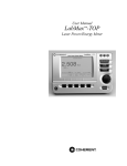
Operator’s Manual
Coherent StingRay Diode Laser Products
Operator’s Manual
Coherent StingRay Diode Laser Products
27650 SW 95th Ave.
Wilsonville, OR 97070
Coherent StingRay Operator’s Manual
This document is copyrighted with all rights reserved. Under the copyright
laws, this document may not be copied in whole or in part or reproduced in
any other media without the express written permission of Coherent, Inc.
Permitted copies must carry the same proprietary and copyright notices as
were affixed to the original. This exception does not allow copies to be
made for others, whether or not sold, but all the material purchased may
be sold, given, or loaned to another person. Under the law, copying
includes translation into another language.
Coherent and the Coherent Logo are trademarks or registered trademarks
of Coherent, Inc. All other trademarks or registered trademarks are the
property of their respective owners.
Patents referenced in this document were active as of the printing date of
the manual (see last page for date). The patents referenced herein may
have expired. You are advised to check to see if the patents are still active:
http://portal.uspto.gov/external/portal/pair.
Every effort has been made to ensure that the data given in this document
is accurate. The information, figures, tables, specifications and schematics
contained herein are subject to change without notice. Coherent makes no
warranty or representation, either expressed or implied with respect to this
document. In no event will Coherent be liable for any direct, indirect,
special, incidental or consequential damages resulting from any defects in
its documentation.
Technical Support
In the US:
Should you experience any difficulties with your laser or need any
technical information, please visit our website: www.Coherent.com.
Additional support can be obtained by contacting our Technical Support
Hotline at 1.800.367.7890 (1.408.764.4557 outside the U.S.), or e-mail
[email protected]. Telephone coverage is available around
the clock (except U.S. holidays and company shutdowns).
If you call outside our office hours, your call will be taken by our answering
system and will be returned when the office reopens.
If there are technical difficulties with your laser that cannot be resolved by
support mechanisms outlined above, e-mail, or telephone Coherent
Technical Support with a description of the problem and the corrective
steps attempted. When communicating with our Technical Support
Department via the web or telephone, the Support Engineer responding to
your request will require the model and Laser Head serial number of your
laser system.
Outside the US:
If you are located outside the U.S., visit our website for technical
assistance or contact our local service representative. Representative
phone numbers and addresses can be found on the Coherent website:
www.Coherent.com.
Coherent provides telephone and web technical assistance as a service to
its customers and assumes no liability thereby for any injury or damage
that may occur contemporaneous with such services. These support
services do not affect, under any circumstances, the terms of any warranty
agreement between Coherent and the buyer. Operation of any Coherent
laser with any of its interlocks defeated is always at the operator's own risk
ii
Table of Contents
TABLE OF CONTENTS
Preface .................................................................................................................................. vi
Export Control Laws Compliance ........................................................................................ vi
Signal Words and Symbols in this Manual .......................................................................... vii
Signal Words............................................................................................................... vii
Symbols ..................................................................................................................... viii
Incoming Inspection ............................................................................................................. ix
Installing the Coherent Connection Software ....................................................................... ix
Section One: Laser Safety ......................................................................................... 1-1
Protecting Devices .............................................................................................................. 1-1
Cap ............................................................................................................................. 1-2
Laser Controller with Safety Interlock for Class IIIb Lasers..................................... 1-2
Laser Safety and Classification........................................................................................... 1-3
Classification ............................................................................................................. 1-3
CDRH Classification ........................................................................................ 1-6
IEC Classification ............................................................................................. 1-6
Classification Requirements ...................................................................................... 1-7
CDRH Requirements ........................................................................................ 1-7
IEC Requirements............................................................................................. 1-8
Declaration of Conformity.................................................................................................. 1-8
Section Two: Laser Operation ................................................................................. 2-1
Power Requirements ........................................................................................................... 2-2
115 or 220 VAC Operation ........................................................................................ 2-2
Turning the Laser ON ......................................................................................................... 2-2
Turning the Laser OFF........................................................................................................ 2-4
Lasers with a Controller...................................................................................................... 2-4
Modulating the Laser .......................................................................................................... 2-4
Operating Environment....................................................................................................... 2-6
Installing a Mounting Bracket ............................................................................................ 2-7
Coherent StingRay and RS-232 .......................................................................................... 2-8
Section Three: Servicing Your Coherent StingRay Laser ...................... 3-1
Focusing Lasers .................................................................................................................. 3-2
Focusing Coherent StingRay Lasers.......................................................................... 3-2
Cleaning the Optics............................................................................................................. 3-2
Cleaning Diffraction Gratings.................................................................................... 3-3
Operating Hints................................................................................................................... 3-3
Section Four: Laser Controller ............................................................................... 4-1
Front Panel .......................................................................................................................... 4-2
Keyswitch .................................................................................................................. 4-2
Status LED Indicators ................................................................................................ 4-3
Interlock Jumper ........................................................................................................ 4-3
iii
Coherent StingRay Operator’s Manual
Back Panel .......................................................................................................................... 4-4
Laser Head Connector ............................................................................................... 4-4
Power In Connector ................................................................................................... 4-4
BNC Connector.......................................................................................................... 4-4
USB Connector .......................................................................................................... 4-5
Specifications...................................................................................................................... 4-5
Section Five: Host Interface ...................................................................................... 5-1
Host Command Quick Reference ....................................................................................... 5-1
Message Considerations ..................................................................................................... 5-2
Communication Port Selection .................................................................................. 5-2
Message Completion Handshake............................................................................... 5-3
Message Terminators ................................................................................................. 5-4
Messages Received by the Laser ...................................................................... 5-4
Messages Sent by the Laser .............................................................................. 5-4
Message Syntax ......................................................................................................... 5-4
Command Prompt ...................................................................................................... 5-5
Commands and Queries ...................................................................................................... 5-5
SCPI Error Codes.............................................................................................................. 5-10
Section Six: Product Repair ...................................................................................... 6-1
Product Shipping Instructions............................................................................................. 6-1
Appendix A: Warranty ............................................................................................... A-1
Glossary ..................................................................................................................... Glossary-1
Index ................................................................................................................................. Index-1
LIST OF FIGURES
1-1.
1-2.
Laser Controller with Safety Interlock ............................................................................ 1-2
Setup for CDRH and IEC Classification ......................................................................... 1-4
2-3.
2-4.
Modulation Curves .......................................................................................................... 2-5
Standard Coherent StingRay with Mounting Bracket...................................................... 2-7
3-5.
Coherent StingRay Focus Ring and Focus Lock ............................................................. 3-2
4-6.
4-7.
Coherent StingRay Controller Front Panel ...................................................................... 4-2
Coherent StingRay Controller Back Panel ...................................................................... 4-4
iv
Table of Contents
LIST OF TABLES
1-1.
Possible CDRH and IEC Classifications for Coherent StingRay Lasers......................... 1-4
2-2.
2-3.
2-4.
2-5.
Pin Out Table ................................................................................................................... 2-2
LED Indicator and Analog Output Status........................................................................ 2-3
Modulation Characteristics and States............................................................................. 2-6
RS-232 Pinouts and Wiring ............................................................................................. 2-8
4-6.
4-7.
Coherent StingRay Controller Status LED States............................................................ 4-3
Coherent StingRay Controller Specifications.................................................................. 4-5
5-1.
5-2.
5-3.
5-4.
Host Command Quick Reference .................................................................................... 5-1
Fault Bit Codes ................................................................................................................ 5-6
Status Code Bit Definitions ............................................................................................. 5-8
SCPI Error Codes........................................................................................................... 5-10
v
Coherent StingRay Operator’s Manual
Preface
This manual contains user information for Coherent StingRay Diode
Laser. Your Coherent StingRay structured light-generating laser
features high quality glass optics that provides uniform intensity
distribution laser light and a rugged housing to maximize the reliability of the laser. For insured longer lifetime, each diode laser has
undergone a burn-in period and a final quality control check before
shipment.
Export Control
Laws Compliance
It is the policy of Coherent to comply strictly with U.S. export
control laws.
Export and re-export of lasers manufactured by Coherent are subject
to U.S. Export Administration Regulations, which are administered
by the Commerce Department. In addition, shipments of certain
components are regulated by the State Department under the International Traffic in Arms Regulations.
The applicable restrictions vary depending on the specific product
involved and its destination. In some cases, U.S. law requires that
U.S. Government approval be obtained prior to resale, export or
re-export of certain articles. When there is uncertainty about the
obligations imposed by U.S. law, clarification must be obtained
from Coherent or an appropriate U.S. Government agency.
Products manufactured in the European Union, Singapore,
Malaysia, Thailand: These commodities, technology, or software are
subject to local export regulations and local laws. Diversion contrary
to local law is prohibited. The use, sale, re-export, or re-transfer
directly or indirectly in any prohibited activities are strictly prohibited.
vi
Preface
Signal Words
and Symbols in
this Manual
This documentation may contain sections in which particular
hazards are defined or special attention is drawn to particular conditions. These sections are indicated with signal words in accordance
with ANSI Z-535.6 and safety symbols (pictorial hazard alerts) in
accordance with ANSI Z-535.3 and ISO 7010.
Signal Words
Four signal words are used in this documentation: DANGER,
WARNING, CAUTION and NOTICE.
The signal words DANGER, WARNING and CAUTION designate the degree or level of hazard when there is the risk of injury:
DANGER!
Indicates a hazardous situation that, if not avoided, will result in
death or serious injury. This signal word is to be limited to the
most extreme situations.
WARNING!
Indicates a hazardous situation that, if not avoided, could result
in death or serious injury.
CAUTION!
Indicates a hazardous situation that, if not avoided, could result
in minor or moderate injury.
The signal word “NOTICE” is used when there is the risk of property damage:
NOTICE!
Indicates information
hazard-related.
considered
important,
but
not
Messages relating to hazards that could result in both personal injury
and property damage are considered safety messages and not property damage messages.
vii
Coherent StingRay Operator’s Manual
Symbols
The signal words DANGER, WARNING, and CAUTION are
always emphasized with a safety symbol that indicates a special
hazard, regardless of the hazard level:
This symbol is intended to alert the operator to the presence of
important operating and maintenance instructions.
This symbol is intended to alert the operator to the danger of
exposure to hazardous visible and invisible laser radiation.
This symbol is intended to alert the operator to the presence of
dangerous voltages within the product enclosure that may be of
sufficient magnitude to constitute a risk of electric shock.
This symbol is intended to alert the operator to the danger of
Electro-Static Discharge (ESD) susceptibility.
This symbol is intended to alert the operator to the danger of
crushing injury.
This symbol is intended to alert the operator to the danger of a
lifting hazard.
viii
Preface
Incoming
Inspection
Immediately upon receipt of your product, examine the packaging
material and contents for shipment damage. Report any such
instance to your receiving department or shipping company.
Your shipment should contain the items shown below.
(1) Coherent StingRay
laser
(1) USB flash drive and (1) Allen key
(1) Laser Safety
and Installation
Quick Start Guide
(1223125)
(1) Final QC report
Installing the
Coherent
Connection
Software
To install the software (P/N 1255080):
1.
Close all programs.
2.
Insert the Coherent StingRay flash drive into a USB port on
your computer.
3.
Double-click the Coherent_Connection_Setup.exe file to start
the installation process.
ix
Coherent StingRay Operator’s Manual
4.
Follow the on-screen instructions.
The Coherent Connection software is an optional interface that,
if enabled, can be used to communicate with the RS-232 feature
of the laser. This software is not required to interface and
communicate with the laser—any serial communication interface can be used. See “Section Five: Host Interface” (p. 5-1) for
protocol and commands
x
Laser Safety
SECTION ONE: LASER SAFETY
In this section:
•
Protecting devices (this page)
•
Laser safety and classification (p. 1-3)
•
Declaration of conformity (p. 1-8)
DANGER!
The laser light emitted by this laser may be in the infrared area
of the electromagnetic spectrum and may not be visible to the
human eye. Use extreme caution at all times when using the
laser.
DANGER!
The output power of this laser is high enough to cause permanent damage to the human eye. Wear appropriate laser safety
goggles at all times when the laser is operational.
Protecting
Devices
WARNING!
Use of controls, adjustments, or performance of procedures
other than those specified herein may result in hazardous radiation exposure and will void the product warranty.
There are two types of protecting devices for your laser:
•
Cap
•
Laser controller with remote interlock (optional)
These are discussed, next.
1-1
Coherent StingRay Operator’s Manual
Cap
The cap serves to protect
the laser during storage or
inactivity. To use the cap,
slide it onto the laser face.
Do not use the cap to block
laser light because the
heated material could
contaminate the optical Cap protecting
the optical head
components.
Laser Controller
with Safety
Interlock for Class
IIIb Lasers
To be used as standalone units, Class IIIb lasers require the installation of a safety mechanism that prevents exposure to the laser light.
As such, if you intend to bring your laser into Class IIIb compliance,
you may wish to purchase a laser controller with safety interlock
(P/N 1225414).
Interlock Jumper
Figure 1-1. Laser Controller with Safety Interlock
The controller has an interlock circuit that must be closed for the
laser to operate—it must have the interlock jumper plugged into it
and the key switched to ON. This means that you can use the Interlock connector two ways:
1.
(for general use) Plug the shorted jack into the safety interlock
and switch ON the key for normal laser operation. After a short
delay, light is emitted from the laser. The laser automatically
shuts off if the shorted jack is not in place.
2.
(for the interlock system) When the interlock circuit is opened,
the laser automatically shuts off. This can be used as a safety
feature. For example, you can connect the two wires of the
1/8” interlock plug to a door contact switch (remove the cover
and solder from the interlock connector, then re-solder the twin
leads to the appropriate pins and replace the cover). Opening
the door will open the Interlock circuit and the laser will turn
off automatically.
1-2
Laser Safety
The laser controller is a multi-functional interface which provide
feedback, status, and control of the laser, in addition to the safety
features, to comply with end-use applications. The controller also
provides interface to the laser for remote connection of power,
modulation, and communication. Features include:
1.
Power to the Laser
2.
Modulation to the laser via the BNC connector
3.
USB interface to the laser for communication and parameter
setting
4.
Visible indication of the laser status
For information on how to install a laser controller into your
Coherent StingRay laser system, refer to the Coherent StingRay
Laser Safety and Installation Quick Start Guide (1223125) that
shipped with your product.
Laser Safety and
Classification
Classification
Lasers are classified based upon the output power and the wavelength of a laser beam in a particular setup according to the United
States Center for Devices & Radiological Health (CDRH) document
21 CFR 1040.10 and upon demand, to the International Electrotechnical Commission (IEC) document 60825-1:2nd edition, 2007-03.
The protocol for classification described herein is a general outline
of the procedures. In actual practice, the settings can differ
depending on the laser. Call us for details.
The laser beam (either as a raw or modified beam) is aimed into a
7 mm aperture located some distance away from the laser. The
sensor placed just behind the aperture records the highest output
power level of the laser beam—see Table 1-1 (p. 1-4) for details. In
the case of a line laser, the entire line is scanned to find the highest
output power.
With conventional Gaussian line generators, it is generally the hot
central spot that causes its safety rating to go up one class (from
CDRH Class II to IIIa, for example). Our optics produce a line of
uniform intensity that does not have a hot spot at the center. Therefore, a Coherent StingRay non-Gaussian laser offers a safer level of
exposure, in addition to more light and uniform illumination transmitted to your part.
1-3
Coherent StingRay Operator’s Manual
200 mm CDRH, 70 or 100 mm IEC
Sensor
Laser Source
7 mm aperture
Figure 1-2. Setup for CDRH and IEC Classification
Table 1-1. Possible CDRH and IEC Classifications for Coherent StingRay Lasers
Organization Class
CDRH
II
400 to 710 nm
1 mW
200 mm
IIIa
400 to 710 nm
5 mW
200 mm
400 to 710 nm
500 mW
200 mm
or > 710 nm
500 mW
200 mm
1
500 to 700 nm
0.39 mW
70 mm
1M
500 to 700 nm
0.39 mW
100 mm
2
400 to 700 nm
1 mW
70 mm
2M
400 to 700 nm
1 mW
100 mm
3R
400 to 700 nm
5 mW
70 mm
3B
400 to 700 nm
500 mW
70 mm
IIIb
IEC
Wavelength
Maximum Powera
Distance For
Some Distance Away
Measuring Powerb
From the Laser Source
a. For the IEC, wavelengths outside of those stated have different maximum
power values.
b. CDRH—between laser aperture and sensor; IEC—between apparent focal
point and sensor.
Generally speaking, the higher the safety class your laser is given,
the higher becomes the risk of eye injury. As a precaution, it is
always advisable to wear appropriate safety goggles to protect
your eyes from harmful radiation and, even for “eye-safe”
classes, the laser beam should never be intentionally aimed at
people.
CDRH Class II and IEC Class 1 and Class 2
Considered eye-safe, including while using optical instruments for
intrabeam viewing. Normal exposure to this type of beam will not
cause permanent damage to the retina, since the blinking reflex of
the human eye is fast enough to avoid any damage. This safety rating
is considered eye-safe, but can be hazardous if there is direct
long-term ocular exposure. Lasers with this rating can be installed
on the shop floor with a minimum of concerns.
1-4
Laser Safety
CDRH Class IIIa and IEC Class 1M, Class 2M, and Class 3R
Considered eye-safe with caution, but may present an eye hazard if
viewed using collecting optics (magnifiers, binoculars, etc.).
Focusing of this light into the eye could cause eye damage.
CDRH Class IIIb and IEC Class 3B
Considered dangerous to your retina if exposed, including exposure
when looking directly into a reflection from a specular (mirror-like)
surface. Normally, lasers from this class will not produce a
hazardous diffuse reflection. At higher levels of the class, these
lasers can be skin hazards. It is important to follow laser safety rules
and wear appropriate protective eyewear when working around
these lasers.
The following directives are taken from section 12.5.2 of
IEC 60825-1, 2001-08, and are good safety measures for both
CDRH Class IIIb and IEC Class 3B lasers:
Class 3B lasers are potentially hazardous if a direct beam or specular
reflection is viewed by the unprotected eye (intrabeam viewing).
The following precautions should be taken to avoid direct beam
viewing and to control specular reflections:
1.
The laser should only be operated in a controlled area.
2.
Care should be exercised to prevent unintentional specular
reflections.
3.
The laser beam should be terminated where possible at the end
of its useful path by a material that is diffuse and of such a
color and reflectivity as to make beam positioning possible
while still minimizing the reflection hazards.
CAUTION!
Conditions for safe viewing of diffuse reflections for Class 3B
visible lasers are: minimum viewing distance of 13 cm between
screen and cornea and a maximum viewing time of 10 sec. Other
viewing conditions require a comparison of the diffuse reflection
exposure with the MPE (maximum permissible exposure limit).
4.
Eye protection is required if there is any possibility of
viewing either the direct or specularly reflected beam, or of
viewing a diffuse reflection not complying with the conditions
of item 3, above.
5.
The entrance to areas should be posted with a standard laser
warning sign.
1-5
Coherent StingRay Operator’s Manual
CDRH Classification
Our lasers can comply with CDRH classification and fall in different
safety classes, depending on output power, wavelength, and fan
angle.
Statement indicating that
laser radiation is emitted
from the aperture. Warning
statement follows.
AVOID EXPOSURE - LASER RADIATION
IS EMITTED FROM THIS APERTURE
** DO NOT REMOVE OPTICS **
(See manual before servicing, safety class may change)
CAUTION
LASER RADIATION DO NOT STARE INTO BEAM
POWER OUTPUT: < 1 mW
WAVELENGTH: 400 - 710 nm
CLASS II OEM LASER COMPONENT
27650 SW 95TH AVENUE, WILSONVILLE, OR 97070
CDRH Class II, IIIa, and IIIb Warning/ID/Aperture Label
Examples
AVOID EXPOSURE - LASER RADIATION
IS EMITTED FROM THIS APERTURE
** DO NOT REMOVE OPTICS **
(See manual before servicing, safety class may change)
DANGER
LASER RADIATION AVOID DIRECT EYE EXPOSURE
POWER OUTPUT: < 5 mW
WAVELENGTH: 400 - 710 nm
CLASS IIIa OEM LASER COMPONENT
27650 SW 95TH AVENUE, WILSONVILLE, OR 97070
Complies with 21 CFR 1040.10(a)(2)
Trademark, company address,
and serial number are
printed on the right side
of the label.
Power output and wavelength
details are located here.
AVOID EXPOSURE - LASER RADIATION
IS EMITTED FROM THIS APERTURE
** DO NOT REMOVE OPTICS **
(See manual before servicing, safety class may change)
DANGER
CDRH laser classification
appears here.
LASER RADIATION AVOID DIRECT EXPOSURE TO BEAM
POWER OUTPUT: < 500 mW
700 - 400
850 nm
WAVELENGTH: 315
CLASS IIIb OEM LASER COMPONENT
27650 SW 95TH AVENUE, WILSONVILLE, OR 97070
Complies with 21 CFR 1040.10(a)(2)
Complies with 21 CFR 1040.10(a)(2)
Statement confirming
laser CDRH compliance
is printed on the bottom
of the label.
IEC Classification
Our lasers can comply with IEC classification (if it is required, make
sure to mention it when ordering) and fall in different safety classes,
depending on output power, wavelength, and fan angle.
1-6
LASER RADIATION
AVOID DIRECT
EYE EXPOSURE
CLASS 3R LASER PRODUCT
IEC 60825-1(2007)
INVISIBLE LASER RADIATION
AVOID DIRECT
EYE EXPOSURE
CLASS 3R LASER PRODUCT
IEC 60825-1(2007)
IEC 60825-1(2007)
IEC 60825-1(2007)
LASER RADIATION
AVOID EXPOSURE TO BEAM
CLASS 3B LASER PRODUCT
IEC 60825-1(2007)
LASER RADIATION
DO NOT STARE INTO BEAM
CLASS 2M LASER PRODUCT
INVISIBLE LASER RADIATION
AVOID EXPOSURE TO BEAM
CLASS 3B LASER PRODUCT
IEC 60825-1(2007)
INVISIBLE LASER RADIATION
DO NOT VIEW DIRECTLY
WITH OPTICAL INSTRUMENTS
CLASS 1M LASER PRODUCT
IEC 60825-1(2007)
LASER RADIATION
DO NOT VIEW DIRECTLY
WITH OPTICAL INSTRUMENTS
CLASS 1M LASER PRODUCT
LASER RADIATION
DO NOT STARE INTO BEAM
CLASS 2 LASER PRODUCT
IEC 60825-1(2007)
CLASS 1 LASER PRODUCT
IEC 60825-1(2007)
IEC Warning/ID/Aperture Label Examples
Laser Safety
Classification
Requirements
Classification is obtained once the laser meets the criteria established by the CDRH or the IEC. Lasers are always classified in a
safety class (CDRH Class II, IIIa, IIIb, and IEC Class 1, 1M, 2, 2M,
3R, 3B).
Lasers do not need to be fully compliant unless the end-user
requires it to be so. If required, make sure to mention it when
ordering.
CDRH Requirements
Class II and IIIa
1.
Laser radiation emission indicator (LED lights up when laser
is powered)
2.
Permanently attached beam attenuator (a shutter)
3.
Warning/ID/aperture label—see “CDRH
(p. 1-6) and “IEC Classification” (p. 1-6)
4.
Instruction manual
Classification”
Class IIIb
1.
All items mentioned for Class II and IIIa lasers
2.
Removable, key-actuated master control preventing lasing
when removed
3.
Remote interlock connector that prevents lasing when
removed
4.
Laser radiation emission indicator that turns on prior to lasing
(LED that lights up 5 to 10 seconds before the laser lights up)
5.
I/O switch
A laser controller can be ordered to fulfill criteria 2, 3, and 4. For
more information, refer to “Laser Controller with Safety Interlock
for Class IIIb Lasers” (p. 1-2).
1-7
Coherent StingRay Operator’s Manual
IEC Requirements
Class 1, 1M, 2, and 2M
1.
Warning/ID/aperture label affixed (sticker on the laser with all
the required information – see above)
2.
Instruction manual
Class 3R
1.
All items mentioned for Class 1, 1M, 2, and 2M lasers
2.
Laser radiation emission indicator (LED turning on when laser
is powered) for lasers > 700 nm
3.
A permanently attached beam attenuator (a shutter or switch)
Class 3B
1.
All items mentioned for Class 3R lasers
2.
Laser radiation emission indicator, regardless of wavelength
3.
Removable, key-actuated master control that prevents lasing
when removed
4.
Remote interlock connector that prevents lasing above Class
1M or 2M when removed
5.
Manual reset mechanism for Class 4
A laser controller can be ordered to fulfill criteria 3 and 4. For more
information, refer to “Laser Controller with Safety Interlock for
Class IIIb Lasers” (p. 1-2).
Declaration of
Conformity
Declaration of Conformity certificates are available upon request.
1-8
Laser Operation
SECTION TWO: LASER OPERATION
In this section:
•
Power requirements (p. 2-2)
•
Turning the laser ON (p. 2-2)
•
Turning the laser OFF (p. 2-4)
•
Lasers with a controller (p. 2-4)
•
Modulating the laser (p. 2-4)
•
Operating environment (p. 2-6)
•
Installing a mounting bracket (p. 2-7)
•
Coherent StingRay and RS-232 (p. 2-8)
DANGER!
The laser light emitted by this laser may be in the infrared area
of the electromagnetic spectrum. The laser light may not be
visible to the human eye. Use extreme caution at all times when
laser is in use.
DANGER!
The output power of these laser is sometimes high enough to
cause permanent damage to the human eye. Wear appropriate
laser safety goggles at all times when the laser is operational.
NOTICE!
Any reference in this manual to the “ON” and “OFF” positions
of the main switch or safety interlock refers to the corresponding
I/O button in the “I” (ON) and “O” (OFF) positions, respectively.
2-1
Coherent StingRay Operator’s Manual
Power
Requirements
The Coherent StingRay laser utilizes an auto scaling input power
feature. The user can apply from 5 to 24 VDC to the system and the
laser will regulate this input voltage to the operating requirement.
Table 2-2. Pin Out Table
Pin
Assignment
Wire Color
1
Vin Gnd
Black
2
Vmod
Blue
3
Vmod Gnd
Red/Black
4
RS232 Recv
Whitea
5
RS232 Gnd
White/Blackb
6
RS232 Trans
Orangec
9
Vin
Red
10
Fault
Green
a. White = RS-232 receive from computer
(serial connector, pin 3)
b. White/Black = RS-232 ground
(serial connector, pin 5)
c. Orange = RS-232 transmit to computer
(serial connector, pin 2)
115 or 220 VAC
Operation
If your laser was ordered with a laser controller, it must be activated
for the laser to function. Refer to “Laser Controller with Safety
Interlock for Class IIIb Lasers” (p. 1-2) for details.
Coherent offers an optional power supply (P/N 1232091) for flying
lead configurations.
Turning the
Laser ON
DANGER!
Do not point the laser towards an eye. You should wear appropriate laser safety goggles at all times when the laser is operational.
2-2
Laser Operation
WARNING!
Use extreme caution at all times when laser is in use.
WARNING!
Do not place any flammable objects directly in front of the free,
non-extended beam (without the line generating optics), especially with higher power beams.
Once the laser is properly connected to the power supply, turn the
power supply ON to operate the laser. The green LED at the back of
the laser will light up—refer to Table 2-3 (p. 2-3).
Table 2-3. LED Indicator and Analog Output Status
Red
Green
Analog Fault Output
Comment
Fault Condition
5 Hz flashing
5 Hz toggling
Reset by cycling power
Health Monitor
0.5 Hz flashing
0.5 Hz toggling
Reset automatically
All other conditions
Pin 1
Steady on
Low
Pin 10
Multi-State LED
Fault
Output
(black &
green)
For information on the controller Status LEDs, refer to Table 4-6
(p. 4-3).
2-3
Coherent StingRay Operator’s Manual
Turning the
Laser OFF
To turn the laser off:
•
Disconnect the power supply from its source.
•
Disconnect the power supply from the laser.
Lasers with a
Controller
The input voltage for a controller is 12 VDC. For more information,
refer to “Laser Controller with Safety Interlock for Class IIIb
Lasers” (p. 1-2).
Modulating the
Laser
The standard laser runs in Continuous Wave mode; however, lasers
can have two power adjustment options. These options must be
chosen at the time of order.
1.
Pulsing and Power Adjustment: Laser power can be modulated or pulsed by using an external signal. Lasers equipped
with this option can be controlled by connecting the followinglines to the modulation source. (other connectors or wires are
only available upon demand)
2.
Modulation Connection: VMod Blue wire, VMod Gnd
Red/Black wire.
To pulse and/or to modulate the laser power:
1.
Mount the laser as desired and follow the procedure for
aligning and focusing—refer to “Focusing Lasers” (p. 3-2).
2.
Provide the laser with power—refer to “Turning the Laser
ON” (p. 2-2).
3.
Supply an appropriate voltage (variable power supply,
computer, manual potentiometer, pulse generator, etc.) to the
appropriate signal lines. As you vary the voltage being applied
to the connector, the output power of the laser will also vary
according to one of the modulation curves shown in Figure 2-3
(p. 2-5).
2-4
Laser Operation
Nominal Power
Laser Power vs.
Analog Modulation
1
0.9
0.8
0.7
0.6
0.5
0.4
0.3
0.2
0.1
0
Indirect
Modulation
Direct
Modulation
0
0.5
1
1.5
2
2.5
3
3.5
4
4.5
5
Vmod [V]
Laser Power vs.
Digital Modulation
1.2
Nominal Power
1
0.8
Indirect
Modulation
0.6
Direct
Modulation
0.4
0.2
0
0
0.5
1
1.5
2
2.5
3
3.5
4
4.5
5
Vmod [V]
Figure 2-3. Modulation Curves
Table 2-4 (p. 2-6) describes the modulation characteristics and states
for given applied voltages.
2-5
Coherent StingRay Operator’s Manual
Table 2-4. Modulation Characteristics and States
Modulation
Fmax
Direct
Indirect
0 to 0.5 VDC 4.5 to 5 VDC
Analog
500 KHz
OFF
0.5 to 5 VDC 0 to 4.5 VDC
LINEAR REGION
0 to 1 VDC
4 to 5 VDC
OFF
TTL
100 KHz
4 to 5 VDC
0 to 1 VDC
ON
1 to 4 VDC
1 to 4 VDC
UNDEFINED
0 to 1 VDC
4 to 5 VDC
OFF
Fast TTL
2 MHz
4 to 5 VDC
0 to 1 VDC
ON
1 to 4 VDC
1 to 4 VDC
UNDEFINED
Operating
Environment
Coherent StingRay lasers are suitable for regular indoor and outdoor
use and function normally when the following environmental conditions are met:
•
Altitudes up to 2000 m.
•
Environments where the maximum relative humidity (RH) is
80% (for temperatures up to 31°C). Note that above 31°C, the
RH decreases linearly from 80 to 50% (at 50°C).
•
Environments in which the diode is soaked –10 to 50°C. In
warmer environments, a heatsink or a thermoelectric cooler
should be used to minimize the heat build-up. In extremely
cold environments, care should be taken to maintain the laser
above –10°C at all times.
NOTICE!
As with all semiconductor materials, avoid prolonged or
repeated exposure to electrostatic charges or water droplets. All
Coherent StingRay lasers are designed with ESD protection.
Operate the laser in an environment in which there is normal aeration.
2-6
Laser Operation
Installing a
Mounting
Bracket
It is important to use a mounting bracket that is specifically designed
to handle the heat dissipation requirements of our lasers, especially
for those operating above 20 mW. Coherent StingRay lasers contain
a built-in temperature monitoring circuit. Should the laser become
too hot, the unit is designed to temporarily shut down. Full laser
operation will only resume once the laser returns to normal operating temperatures and power is cycled.
If you would like to have a mounting bracket (P/N 1222896) shipped
with your laser, make sure to mention it at the time you place the
order. The standard mounting bracket has 4 thru-holes or M3
metric-threaded holes from the bottom for easy mounting. Once
attached to the assembly, slide the laser (front end first) into the
mount. Position the laser so there is full accessibility to the focusing
element. Tighten the clamp on the laser mount.
Mounting
Area
R .47 in.
[11.94 mm]
R .380 in. THRU
[9.652 mm]
.61 in.
[15.49 mm]
.57 in.
[14.36 mm]
1.24 in.
[31.37 mm]
Figure 2-4. Standard Coherent StingRay with Mounting Bracket
NOTICE!
Always ensure that any support on which the laser is mounted is
not made of insulating material, and that the heat of the laser
can be properly transferred.
2-7
Coherent StingRay Operator’s Manual
Coherent
StingRay and
RS-232
RS-232 can be connected directly to the laser via a flying lead or
Hirose connector. For a list of RS-232 commands, refer to “Section
Five: Host Interface” (p. 5-1). For a complete list of pin outs, refer
to Table 2-2 (p. 2-2).
Table 2-5. RS-232 Pinouts and Wiring
Pin Assignment Wire Color
4
RS232 Recv
Whitea
5
RS232 Gnd
White/Blackb
Pin 4
6
RS232 Trans
Orangec
Pin 5
Pin 6
Recv
Gnd
Trans
a. White = RS-232 receive from computer (serial connector, pin 3)
b. White/Black = RS-232 ground (serial connector, pin 5)
c. Orange = RS-232 transmit to computer (serial connector, pin 2)
2-8
Servicing Your Coherent StingRay Laser
SECTION THREE: SERVICING YOUR COHERENT
STINGRAY LASER
In this section:
•
Focusing lasers (p. 3-2)
•
Cleaning the optics (p. 3-2)
•
Operating hints (p. 3-3)
WARNING!
Due to our optical design, most of our visible laser products are
classified as CDRH Class II and IIIa products. These structured
light devices meet this classification only as complete assemblies.
Removal of the optical head (image generating optics) for
cleaning could expose personnel to hazardous laser radiation
(sometimes equivalent to a Class IIIb/3B laser) and will void the
product safety classification. Turn the laser off whenever the
optical head is removed unless alignment is being performed.
Use extreme caution when performing these servicing operations and wear appropriate eyewear at all times. Servicing operations have to be performed by personnel trained to manipulate
Class IIIb/3B lasers. Never look directly at a raw laser beam.
Coherent will not be held liable for any injuries caused by
product misuse.
WARNING!
Use caution around all laser products. Lasers are highly concentrated light sources, some invisible to the eye. Never point a laser
beam into your eyes or the eyes of another person—permanent
damage to the retina can occur!
WARNING!
Use of controls, adjustments, or performance of procedures
other than those specified herein may result in hazardous radiation exposure and will void the product warranty.
3-1
Coherent StingRay Operator’s Manual
Each Coherent StingRay laser is a self-contained unit and, as such,
the only required service and maintenance procedures are explained
in detail later in this section.
Focusing Lasers
All lasers have been designed so that the focusing lens cannot be
removed. If you have a specific application that requires accurate
focusing and you would like your laser to be pre-focused using a
beam profiler, contact your sales representative or Coherent.
Focusing
Coherent StingRay
Lasers
Coherent StingRay is equipped with a state of the art translation
focus mechanism. To focus the laser:
1.
Using the 0.035 hex Allen wrench (provided), loosen the focus
lock.
2.
Grasp the focus ring and rotate the focus until it reaches the
desired minimum thickness at the working distance you are
using the laser.
3.
Tighten the focus lock.
Focus
Ring
Focus
Lock
Figure 3-5. Coherent StingRay Focus Ring and Focus Lock
Cleaning the
Optics
If the laser pattern becomes fuzzy or unclear:
•
Confirm that the image is focused. If it is not focused, follow
the instructions under the “Focusing Coherent StingRay
Lasers” heading, above.
3-2
Servicing Your Coherent StingRay Laser
•
Verify that the optics are not contaminated. If the optics are
contaminated, it is best to try and remove visible contamination by blowing dry air across the surface. Make sure the air
product is oil- and moisture-free. If this technique fails to
remove the contaminants, gently wipe the glass surface with a
piece of slightly damp lens tissue.
Cleaning
Diffraction
Gratings
All lasers projecting a pattern other than a dot, a single line, or a
crosshair, have a diffraction grating. If your laser has a diffraction
grating, only use a sterile jet of nitrogen or air to clean the surface of
the grating. Using other products will cause damage.
Operating Hints
A broad line or band of light can be projected (line-generating lasers
only) by slightly de-focusing the laser source. Follow the instructions under “Focusing Lasers” (p. 3-2), but try to enlarge the image
spot at your desired target distance. A larger dot area at the focus
distance creates a dimmer pattern. Try to determine the best focused
spot size for your band of light application.
The angle of illumination and detection can greatly enhance a characteristic or defect you may be trying to capture. If physical parameters allow, optimize the camera or sensor position relative to the
laser position. See the examples in the following figure.
CCD
camera
CCD
camera
Laser
Computer
Computer
Sheet-of-light
Workpiece
(a)
Laser
(b)
(a) A laser at a steep angle can be useful for edge, trim, and insertion
detection.
3-3
Coherent StingRay Operator’s Manual
(b) A laser mounted at a low angle tends to highlight surface topography and edge characteristics. This has proven to be useful in such
applications as semiconductor orientation systems or magazine and
newspaper counting systems. As the material moves by, the lines are
bent by the edges and a vision system counts the bent line shapes.
3-4
Laser Controller
SECTION FOUR: LASER CONTROLLER
In this section:
•
Front panel (p. 4-2)
•
Back panel (p. 4-4)
•
Specifications (p. 4-5)
The Coherent StingRay Controller is a small control box that allows
you to connect to—and interface with—a single laser head.
Coherent StingRay Controllers are “stackable,” which permits
multiple controllers to be set up in a single system.
NOTICE!
To be CDRH compliant, you must use a Coherent StingRay
Controller with the laser head—the laser head alone is not
CDRH compliant.
The Coherent StingRay Controller offers an ON/STANDBY
keyswitch, a remote interlock, and an emission indicator. With these
safety features, the system is CDRH compliant.
NOTICE!
In RS-232-enabled units, the CDHR Delay flag can be turned on
or off. If the flag is ON, the laser will begin emitting 3 seconds
after power is applied. In units that do not have this feature, the
default is OFF.
The modulation BNC connector is used for analog or digital modulation or variable power control. Review Analog Modulation specifications for input requirements.
4-1
Coherent StingRay Operator’s Manual
Front Panel
Indicators and connectors on the Coherent StingRay Controller front
panel are shown in the following figure.
Status LEDs
Keyswitch
(showing key in
STANDBY position)
Interlock
Jumper
Figure 4-6. Coherent StingRay Controller Front Panel
Keyswitch
This is a single keyswitch master power control for laser emission
supply.
Keyswitch
Power On
LED Indicator
The following illustration shows the keyswitch in the STANDBY
and the ON positions.
STANDBY Position
ON Position
4-2
Laser Controller
Status LED
Indicators
There are three Status LEDs on
the front panel:
•
Laser Ready
•
Laser Fault
•
Power On
The following table lists all the possible states of the controller
Status LEDs.
Table 4-6. Coherent StingRay Controller Status LED States
Action
Ready Fault
On
No power
Power to Control board
Power to Laser
Interlock disconnect
Interlock reapplied after disconnect
(must toggle keyswitch to reset)
Fault
Flashing
For information on the laser Status LED, refer to Table 2-3 on
page 2-3.
Interlock Jumper
This is a mechanical-style jumper for
CDRH interlock. The interlock has
terminal style connections that allow
connection to an external control
device.
Shorting
Jumper
4-3
Coherent StingRay Operator’s Manual
Back Panel
The back panel of the Coherent StingRay Controller (Figure 4-7,
below) has the following connectors: laser head, power in, BNC, and
USB.
BNC
Connector
Laser Head
Connector
USB
Connector
Power In
Connector
Figure 4-7. Coherent StingRay Controller Back Panel
Laser Head
Connector
Use this connector to connect the Coherent
StingRay laser to the Controller.
Power In
Connector
Power is supplied to the Coherent
StingRay Controller through a l mm
barrel connector. The Coherent StingRay
Controller, in turn, supplies power to the
laser head through a 12-pin connector.
A power supply for the Controller can be
purchased separately from Coherent
(P/N 1105427).
BNC Connector
The BNC connector provides a path for the
modulation signal to pass from an external
source to the laser while connected to the
Controller. Both Analog and Digital signals can
be applied to this connection.
4-4
Laser Controller
USB Connector
This Mini-B connector allows you to connect a
PC to the Coherent StingRay Controller and
issue commands. The commands pass to the
laser via RS-232. The controller converts the
USB signal to RS-232.
Specifications
Table 4-7. Coherent StingRay Controller Specifications (Sheet 1 of 2)
Parameter
Specification
Coherent StingRay Controller dimensions
84.5 x 108.5 x 30.0 mm
Laser-In connectors
One
Operating temperature range
10 to 50°C
Operating humidity range
30 to 85%
Storage temperature range
-20 to 70°C
Storage humidity range (non-condensing)
30 to 95%
Interlock(s)
One keyswitch
One dual pin
Power input
12V ± 2 VDC
Mechanical expandability
No
Modulation capability
Pass-through only; 50 Ohm
Modulation connectors
One input: pass-through
Modulation connector style
BNC
LEDs
READY - On conditions
Power to Laser; Fault
FAULT - On conditions
Laser Fault
ON - On conditions
- Power to Controller
- Power to Laser
- Interlock and Fault conditions
Laser I/O Connector
1. Laser power
12V ± 2 VDC
2. Laser power
Connected to Pin 1
3. GND
Ground
4. Communications input
Host input signal - RS-232 signal
5. GND
Ground
6. GND
Ground
7. GND
Ground
8. Communications output
Host output signal - RS-232 signal
9. Modulation GND
Modulation ground
10. Modulation signal
Modulation input signal - Coherent StingRay pass-through
11. GND
Ground
12. Laser fault signal
0V - fault; open collector input
4-5
Coherent StingRay Operator’s Manual
Table 4-7. Coherent StingRay Controller Specifications (Sheet 2 of 2)
Parameter
Specification
Communications protocol to laser
RS-232
USB connector
One
Power-In connector
Kycon KLDX-SMT-0202-AP
RS-232 connector
DB-9 standard female
Laser-In connector
Hirose 12-pin HR10A-10R-12PB(72)
4-6
Host Interface
SECTION FIVE: HOST INTERFACE
In this section:
•
Host command quick reference (this page)
•
Message considerations (p. 5-2)
•
Commands and queries (p. 5-5)
•
SCPI error codes (p. 5-10)
When a command is sent to the Coherent StingRay laser, the
parameter for the command is stored in internal persistent
memory, which has a logic cell life of 10 thousand cycles. The cell
life sets the limits for repetitive commands sent to the Coherent
StingRay laser.
This only applies to commands and not queries.
Host Command
Quick
Reference
The following table gives a brief description of all host commands
and queries. For detailed information about a specific command or
query, go to the page referenced in the right-hand column.
Table 5-1. Host Command Quick Reference (Sheet 1 of 2)
Command
Description
Page
No.
*IDN?
Device ID query
5-5
SYST:CDRH
Enables/disables 5-second CDRH delay
5-5
SYST:CDRH?
Queries CDRH delay state
5-5
SYST:COMM:BAUD
Sets serial communication baud rate
5-6
SYST:COMM:BAUD?
Queries serial communication baud rate
5-6
SYST:COMM:HAND
Enables/disables SCPI handshaking
5-6
SYST:COMM:HAND?
Queries SCPI handshaking state
5-6
SYST:COMM:PROM
Enables/disables interactive prompt
5-6
SYST:COMM:PROM?
Queries interactive prompt state
5-6
SYST:DIOD:HOUR?
Queries laser diode usage hours
5-6
SYST:FAUL?
Queries system fault
5-6
SYST:INF:CDAT?
Queries factory calibration date
5-7
5-1
Coherent StingRay Operator’s Manual
Table 5-1. Host Command Quick Reference (Sheet 2 of 2)
Command
Description
Page
No.
SYST:INF:FVER?
Queries firmware version
5-7
SYST:INF:MDAT?
Queries manufacture date
5-7
SYST:INF:MOD?
Queries Coherent laser model
5-7
SYST:INF:PNUM?
Queries Coherent part number
5-7
SYST:INF:POW?
Queries laser power in Watts at maximum calibrated output
5-7
SYST:INF:SNUM?
Queries serial number
5-7
SYST:INF:USER
Enters and stores user-defined identification
5-7
SYST:INF:USER?
Queries user-defined name
5-7
SYST:INF:WAV?
Queries laser wavelength
5-8
SYST:STAT?
Queries system status
5-8
SOUR:AM:MPOL?
Queries modulation input polarity
5-8
SOUR:AM:SOUR?
Queries device operating mode
5-8
SOUR:AM:STAT
Switches laser on/off
5-8
SOUR:AM:STAT?
Queries laser on/off state
5-8
SOUR:CUR:LEV?
Queries diode operating current
5-8
SOUR:POW:LEV?
Queries diode operating power
5-9
SOUR:POW:LEV:IMM:AMPL
Sets laser output power in Watts for CW power mode
5-9
SOUR:POW:LEV:IMM:AMPL?
Queries laser output power in Watts for CW power mode
5-9
SOUR:POW:NOM?
Queries laser nominal power
5-9
SOUR:TEMP:DIOD?
Queries diode temperature
5-9
SOUR:TEMP:INT?
Queries internal temperature
5-9
SOUR:TEMP:PROT:DIOD:LOW? Queries laser diode low temperature limit
5-9
SOUR:TEMP:PROT:DIOD:HIGH? Queries laser diode high temperature limit
5-9
Message
Considerations
Communication
Port Selection
The laser head uses RS-232 serial port for host communications. If
the laser head is connected to a Coherent StingRay controller, the
communication with host is through USB port. The communication
protocol described within this section works identically on either
port.
5-2
Host Interface
Message
Completion
Handshake
SCPI message round trip handshaking is implemented on every
message sent by the laser head firmware; however, the handshaking
may be disabled using an SCPI command. Change of the setting will
be saved in non-volatile memory.
This handshake serves several purposes:
1.
It provides an indication to the host/controller that the message
was received
2.
It provides a synchronization mechanism to the host/controller
so it will know when a message has been processed to completion so a new message may be sent
3.
It provides the host/controller with an indication of any errors
that may have occurred.
The handshake is a short message string that is sent as the last action
performed when handling a received message. The handshake string
represents either an OK response or an error response if a received
message raises an error condition.
Note that quotation marks as depicted here are never included in the
handshake string.
The OK response is formatted as “OK\r\n”.
Error responses are formatted as “ERR<n>\r\n” where <n> represents the error code number. Negative numbers are permitted in the
error string.
When handshaking is enabled, Coherent StingRay devices transmit
one of the following handshake reply strings in response to each
received command or query:
•
Valid commands with valid data parameters will reply with
“OK\r\n”
•
Valid queries with any optional valid data reply as explicitly
defined elsewhere in this section, followed by “OK\r\n”. For
example, if querying the model name string, the laser will
transmit the model name string followed by the “OK\r\n”
string.
•
Valid commands or queries which result in an error reply with
“ERR<n>\r\n”
•
Unrecognized or unsupported commands or queries reply with
“ERR-100\r\n”
5-3
Coherent StingRay Operator’s Manual
Message
Terminators
Messages between the laser head or controller and the host computer
are comprised entirely of ASCII string characters; no binary
messages are supported. All message strings passing through the
host interface are terminated to signal the end of a message string.
The maximum message length supported is 255 bytes, which
includes all terminating characters.
Messages Received
by the Laser
Messages received by the laser head or controller must be terminated by a carriage return (decimal 13). A line feed (decimal 10)
following the carriage return is ignored so messages may be terminated with a carriage return and line feed pair. A command or query
is considered incomplete without proper termination.
Messages Sent by the
Laser
All messages sent by the laser head or controller are terminated by a
carriage return (decimal 13) and line feed (decimal 10) pair. The
maximum length of any message sent by the laser is limited to 255
bytes, including all terminating characters.
Message Syntax
Syntax specified by the SCPI and IEEE 488.2 Standards is followed
unless otherwise specified. Refer to the SCPI and IEEE 488.2 Standards for more information.
Notably, the base-10 numeric data format specification is used
heavily in this document and covered in the IEEE 488.2 Standard.
Unless otherwise specified, numeric data items referred to as NRf
(IEEE flexible numeric representation) are interchangeable and may
be represented in any of these formats:
•
integer values
•
non-scientific notation floating point values
•
scientific notation floating point values (uppercase or
lowercase E)
For example, the following data values are functionally equivalent:
•
31256
•
31256.0
•
3.1256E4
•
31.256E3
•
+3.1256E+4.
Unless otherwise specified, non-numeric data items (typically
referred to as strings) are not quoted.
5-4
Host Interface
Devices interpret hexadecimal data using the following rules:
•
Uppercase and lowercase are accepted (“FE” is the same as
“fe”)
•
Leading zeroes are required and accepted (“0A” is the same as
“A”)
•
The data string may optionally be preceded by a “0x” or “0X”
C hexadecimal notation idiom (0xD2C4 is the same as D2C4)
•
Following the optional “0x” prefix, the acceptable characters
are from the list: 0, 1, 2, 3, 4, 5, 6, 7, 8, 9, a, b, c, d, e, f, A, B,
C, D, E, and F
Enumerated values must match exactly, using the long form/short
form comparison rules defined under the SCPI Standard.
Dates (manufacturing date, calibration date, etc.) will use the
YYYYMMDD format. Using this format, dates may be stored as
ASCII strings or as numeric long integers and converted easily from
one format to the other.
Command Prompt
Each device implements the ability to output a command prompt to
support interactive operation by an operator typing commands in a
terminal program. A command has been specified to describe the
command prompt behavior.
Commands and
Queries
*IDN?
Device ID query.
Query: *IDN?
Return: Coherent, Inc - StingRay - <firmware version> - <firmware
build date>
SYST:CDRH
NOTICE!
Disabling the CDRH delay will render the Coherent StingRay
system non-CDRH compliant.
5-second CDRH delay control command (persistent).
Command: SYST:CDRH {ON|OFF}
Query: SYST:CDRH?
5-5
Coherent StingRay Operator’s Manual
SYST:COMM:BAUD
Serial communication baud rate control command (persistent).
Command: SYST:COMM:BAUD <baud rate>
Query: SYST:COMM:BAUD?
Note: Default = 115200.
SYST:COMM:HAND
SCPI handshaking control command (persistent).
Command: SYST:COMM:HAND {ON|OFF}
Query: SYST:COMM:HAND?
SYST:COMM:PROM
Interactive prompt control command (persistent).
Command: SYST:COMM:PROM {ON|OFF}
Query: SYST:COMM:PROM?
SYST:DIOD:HOUR?
Queries laser diode usage hour.
Query: SYST:DIOD:HOUR?
Return: Hours in x.xx format.
Note: The usage hours are saved to persistent memory every 15
minutes.
SYST:FAUL?
System fault query - returns bit-coded fault conditions.
Query: SYST:FAUL?
The following table describes fault code bit mapping.
Table 5-2. Fault Bit Codes
Bit Mask
Bit Label
Definition
1
2
Diode Temperature Fault
Diode temperature out of range
2
4
Internal Temperature Fault Internal temperature out of range
4
10
12C Error
12C bus error
5
20
Over Current
Diode over current
6
40
Laser Checksum Error
Persistent memory checksum error
17
20000 Watchdog Timer Reset
Firmware resumed from watchdog reset
19
80000 Diode End of Life
Laser diode reaches end of life
5-6
Host Interface
SYST:INF:CDAT?
Queries factory calibration date.
Query: SYST:INF:CDAT?
SYST:INF:FVER?
Queries firmware version.
Query: SYST:INF:FVER?
Return: Version in format VX.X.X.
SYST:INF:MDAT?
Queries manufacture date.
Query: SYST:INF:MDAT?
SYST:INF:MOD?
Queries Coherent laser model.
Query: SYST:INF:MOD?
Return: “STINGRAY” as default.
SYST:INF:PNUM?
Queries Coherent part number.
Query: SYST:INF:PNUM?
SYST:INF:POW?
Queries laser power in Watts at maximum calibrated output.
Query: SYST:INF:POW?
SYST:INF:SNUM?
Queries serial number.
Query: SYST:INF:SNUM?
SYST:INF:USER
Enters and stores user-defined identification (persistent). Queries
user-defined name.
Command: SYST:INF:USER {0,<character string>}
Query: SYST:INF:USER?
Return: “STINGRAY” as default.
5-7
Coherent StingRay Operator’s Manual
SYST:INF:WAV?
Queries laser wavelength in nanometers.
Query: SYST:INF:WAV?
SYST:STAT?
System status query.
Query: SYST:STAT?
Return: Bit-coded laser operational status.
The following table describes status code bit mapping.
Table 5-3. Status Code Bit Definitions
Bit Mask
Bit Label
Definition
0
1
Laser Fault
Any laser faults
1
2
Laser Emission
Laser emission status
2
4
Laser Ready
Laser ready status
3
8
Laser Standby
Laser standby status
4
10
CDRH Delay
Laser CDRH delay status
5
20
Laser Hardware Fault Any hardware faults
SOUR:AM:MPOL?
Queries modulation input polarity control command (persistent)
(ON = PASS, OFF = INVERT).
Query: SOUR:AM:MPOL?
SOUR:AM:SOUR?
Queries device operating mode (constant power, external analog,
digital, or fast digital modulation).
Query: SOUR:AM:SOUR?
SOUR:AM:STAT
Laser on/off control command.
Command: SOUR:AM:STAT {ON|OFF}
Query: SOUR:AM:STAT?
SOUR:CUR:LEV?
Queries diode operating current in Amps.
Query: SOUR:CUR:LEV?
5-8
Host Interface
SOUR:POW:LEV?
Queries diode operating power in Watts.
Query: SOUR:POW:LEV?
SOUR:POW:LEV:IMM:AMPL
Laser output power control command for CW power mode (persistent).
Command:
Watts>}
SOUR:POW:LEV:IMM:AMPL
<laser
Query: SOUR:POW:LEV:IMM:AMPL?
SOUR:POW:NOM?
Queries laser nominal power in Watts.
Query: SOUR:POW:NOM?
SOUR:TEMP:DIOD?
Queries diode temperature.
Query: SOUR:TEMP:DIOD?
Return: Value in Celsius degrees.
SOUR:TEMP:INT?
Queries laser internal temperature.
Query: SOUR:TEMP:INT?
Return: Value in Celsius degrees.
SOUR:TEMP:PROT:DIOD:LOW?
Queries laser diode low temperature limit (degrees C).
Query: SOUR:TEMP:PROT:DIOD:LOW?
SOUR:TEMP:PROT:DIOD:HIGH?
Queries laser diode high temperature limit (degrees C).
Query: SOUR:TEMP:PROT:DIOD:HIGH?
5-9
power
in
Coherent StingRay Operator’s Manual
SCPI Error Codes
Table 5-4. SCPI Error Codes
Error
Code
SCPI_ERROR_QUEUE_OVERFLOW
SCPI_ERROR_SYSTEM_ERROR
SCPI_ERROR_NONE
SCPI_ERROR_UNRECOGNIZED
SCPI_ERROR_INVALID_PARAM
SCPI_ERROR_DATA_ERROR
-350
-310
0
100
101
102
5 - 10
Product Repair
SECTION SIX: PRODUCT REPAIR
Each Coherent StingRay laser has been designed to exhibit proper
mechanical and temperature stability. As such, no user-serviceable
parts are located inside the laser. Do not attempt to take the
assembly apart—this will void the product warranty.
NOTICE!
Coherent recommends that the shipping box and packing materials be saved after initial purchase, as they will be required
should the laser need to be shipped or returned.
Product
Shipping
Instructions
To prepare the product for shipping:
1.
Repack the laser in the packaging insert.
2.
Repack the insert into the original shipping box.
3.
Close the box and tape it securely.
4.
Obtain a Coherent RMA number by contacting our Technical
Support Hotline at 1.800.367.7890 (1.408.764.4557 outside
the U.S.), or by e-mailing [email protected].
5.
Fill out a shipping label and attach it to the outside of the box.
Make sure to include the Coherent RMA number on the shipping label.
6- 1
Coherent StingRay Operator’s Manual
6-2
Warranty
APPENDIX A: WARRANTY
Each Coherent StingRay laser has been designed to exhibit proper
mechanical and temperature stability. As such, no user-serviceable
parts are located inside the laser. Do not attempt to take the
assembly apart, as any such action will void the product
warranty.
Coherent StingRay lasers are guaranteed to be free from material
and manufacturing defects for a period of two years from the date of
shipment, with the exception of products that have a wavelength <
635 nm, which have a warranty of one year. Should a product fail
during this period, Coherent will, at its discretion, repair or replace
the damaged unit. Repaired or replacement units will be covered for
the remainder of the original equipment warranty period. The
warranty does not apply to units examined by Coherent that are
found to have failed due to abuse, acts of nature, mishandling, alteration, improper installation, or negligence.
A-1
Coherent StingRay Operator’s Manual
A-2
Glossary
GLOSSARY
ANSI
American National Standards Institute. An organization that
generates the ANSI Z136.1 Standard for the Safe Use of lasers and
other safety standards for laser users.
Collimation
The process by which a divergent beam of radiation is converted to
a parallel beam. A diode laser focused at more than about 45 inches
is said to be “collimated” for all practical purposes.
CCD
Acronym for Charged Couple Device. In common terms, it is the
semiconductor chip that is used to collect light and convert it into a
digital image. The conversion process involves grabbing the
collected light from small sections of the chip in a continuous
fashion similar to a television screen. The data is typically taken
every 1/30th of a second.
CDRH
Center for Devices and Radiological Health. A regulatory
organization that publishes legal regulations for laser product
manufacturers, applicable in the U.S.
CW
An acronym for Continuous Wave. A term used to describe the
output of a laser emitting radiation continuously rather than in short
bursts.
Depth-of-Field
The physical distance one can move the image plane (+/-) without
affecting the focused image sharpness by more than 1.4 times its
smallest size.
Fan Angle
The (full) angle at which light “fans out” from the front of the laser,
to form the image. Used to determine the “length” of a projected line
at a fixed distance from the laser source.
IEC
International Electrotechnical Commission. An organization that
publishes the IEC 60825-1 laser safety standard.
Infrared (IR)
The invisible portion of the electromagnetic spectrum that lies
between 0.75 and 1000 µm. All IR Coherent StingRay lasers emit in
the region of 780 nm to 1550 nm (near IR).
Interbeam Angle
The interbeam angle is the angle between two diverging light images
from a single source. It is used to determine how far apart the
projections (that is, dots, lines, etc.) will be from one another at a
distance D from the source.
Modulation
A change in the output level generated by a change in supplied
voltage.
Nanometer
A unit of length in the metric system equal to 10-9 meter.
Glossary - 1
Coherent StingRay Operator’s Manual
Structured Light
A term used in Machine Vision applications to describe any light
source that projects a known geometric distribution of light.
Visible
The region of the electromagnetic spectrum which is visible by the
human eye. Light in the visible region falls between 400 and
700 nm.
Wavelength
Electromagnetic energy is transmitted in the form of a sinusoidal
wave. The wavelength is the physical distance covered by one cycle
of this wave. Wavelength is inversely proportional to the frequency.
Glossary - 2
Index
INDEX
C
M
Cap, protecting device 1-2
Classification
Laser 1-3
Laser requirements 1-7
Cleaning
Diffraction Gratings 3-3
Optics 3-2
Coherent StingRay and RS-232 2-8
Coherent StingRay laser, servicing 3-1
Commands and queries 5-5
Communication port selection 5-2
Compliance, U.S. export control laws -vi
Message
Completion handshake 5-3
Syntax 5-4
Terminators 5-4
Message considerations
Communication port selection 5-2
Message completion handshake 5-3
Message syntax 5-4
Message terminators 5-4
Modulating the laser 2-4
O
Declaration of conformity 1-8
Diffraction gratings, cleaning 3-3
Operating
Environment, laser
Hints 3-3
Optics, cleaning 3-2
E
P
D
Error codes, SCPI
5-10
Power requirements 2-2
115 or 220 VAC operation 2-2
Product
Repair 6-1
Shipping instructions 6-1
Protecting devices 1-1
Cap 1-2
Laser controller with remote interlock for class IIIb
lasers 1-2
F
Focusing
Coherent StingRay lasers
Lasers 3-2
3-2
H
Hints, operating 3-3
Host
Command quick reference
Interface 5-1
2-6
5-1
Q
Quick reference, host command
I
5-1
R
Incoming inspection -ix
Inspection, incoming -ix
Repair, product 6-1
RS-232 and Coherent StingRay
L
Laser
Classification 1-3
Classification requirements 1-7
Controller with remote interlock for class IIIb lasers,
protecting device 1-2
Declaration of conformity 1-8
Operating environment 2-6
Safety 1-1
Safety and classification 1-3
Turning off 2-4
Turning on 2-2
Lasers
Focusing 3-2
Focusing Coherent StingRay 3-2
With a controller 2-4
2-8
S
Safety, laser 1-1
SCPI error codes 5-10
Servicing your Coherent StingRay laser 3-1
Shipping instructions, product 6-1
Signal words and symbols in this manual -vii
T
Turning the laser
Off 2-4
On 2-2
U
U.S. export control laws compliance
W
Warranty
Index - 1
A-1
-vi
Coherent StingRay Operator’s Manual
Index - 2
Coherent StingRay Operator’s Manual
©Coherent Inc., 8/2013(RoHS), printed in the USA
Part No. 1223124 Rev. AD