1
CobraNet
Digital Audio Networking Processor
CobraNet
™
Programmer’s Reference
Version 2.5
Preliminary Product Information
This document contains information for a new product.
Cirrus Logic reserves the right to modify this product without notice.
©Copyright 2006 Cirrus Logic, Inc.
http://www.cirrus.com
FEB ’06
DS651PM25
CobraNet
Features
Digital Audio Networking Processor
CobraNet
Asynchronous serial interface
❒
❒
❒
❒
❒
❒
❒
❒
❒
❒
❒
❒
❒
❒
❒
❒
❒
Real-time Digital Audio Distribution via Ethernet
No Overall Limit on Network Channel Capacity
Supports Switched and Repeater Fast Ethernet Networks
Fully IEEE 802.3 Ethernet Standards Compliant
Fiber Optic and Gigabit Ethernet Variants Supported
Ethernet infrastructure can be used simultaneously for
audio and data communications.
Free CobraCAD™ Audio Network Design Tool
High-quality Audio Sample Clock Delivery Over Ethernet
Uncompressed 16-, 20-, and 24-bit Audio Transport
Professional 48 khz and 96 kHz Sample Rate
Low (1-1/3 ms) Latency
Flexible Many-to-many Network Audio Routing
Capabilities
Available in a family of modules and low-cost devices,
most without licensing fees or royalties.
CobraNet Interface
❒ Auto-negotiating, 100-Mbit, Full-duplex Ethernet
Connections
❒ Up to 64 Audio Channel I/O Capability
❒ Implements CobraNet protocol for real-time transport of
audio over ethernet.
❒ Local Management via 8-bit Parallel Host Port
❒ UDP/IP Network Stack with Dynamic IP Address
Assignment via BOOTP or RARP
❒ Remote Management via Simple Network Management
Protocol (SNMP)
❒ Available module form factor allows for flexible integration
into audio products.
❒ 120-MIPS Digital Signal Processor
❒ Non-volatile Storage of Configuration Parameters
❒ Safely Upgrade Firmware over Ethernet Connection
❒ LED Indicators for Ethernet Link Activity, Conductor
Status, and Fault Annunciation
❒ Watchdog Output for System Integrity Assurance
❒ Comprehensive Power-on Self Test (POST)
❒ Error and Fault Reporting and Logging Mechanisms
Full-duplex Capable
8- and 9-bit Data Formats
Standard Baud Rates up to 115.2 kbps
Transmitter Tri-state Control for Multi-drop Networking
Synchronous Serial audio Interface
❒ 4 Bi-directional Interfaces Supporting Up to 64 Channels
of Audio I/O
❒ 48 kHz and 96 kHz Sample Rates
❒ 64FS, 128FS, and 256FS Bit Rates Supported
❒ Supports numerous synchronous serial formats including
I2S
❒ Up to 32-bit Data Resolution
Audio clock interface
❒ 4 Host Audio Clocking Modes for Maximum Flexibility in
Digital Audio Interface Design
❒ Low-jitter, 512FS (24.576 MHz) Master Clock Oscillator
❒ Synchronize to Supplied Master and/or Sample Clock
❒ Sophisticated jitter attenuation assures network
perturbations do not affect audio performance.
Audio routing and processing
❒ Single-channel Granularity in Routing from Synchronous
Serial Audio Interface to CobraNet Network
❒ Two levels of audio routing indirection absorbs any quirks
in audio I/O interface design in host system.
❒ Local Audio Loopback and Output Duplication Capability
❒ Peak-reading Audio Metering with Ballistics
Host Interface
❒
❒
❒
❒
❒
2
8-bit Data, 3- or 4-bit Address
Virtual 24- or 32-bit Data and Addressing
Polled, Interrupt, and DMA Modes of Operation
Configure and Monitor CobraNet Interface
Transmit and Receive Ethernet Packets at 100-Mbit Wire
Speed
©Copyright 2006 Cirrus Logic, Inc.
DS651PM25
CobraNet
General Description
Digital Audio Networking Processor
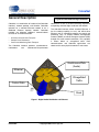
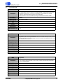
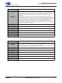
CobraNet is a combination of hardware (the CobraNet
interface), network protocol, and firmware. CobraNet
operates on a switched Ethernet network or on a
dedicated Ethernet repeater network. CobraNet
provides the following additional communications
services for an Ethernet network.
•
•
•
Isochronous Audio Data Transport
Sample Clock Distribution
Control and Monitoring Data Transport
The CobraNet interface performs synchronous-toisochronous
and
isochronous-to-synchronous
conversions as well as the data formatting required for
transporting real-time digital audio over the network.
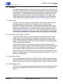
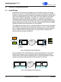
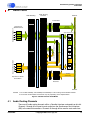
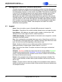
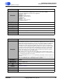
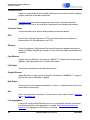
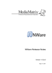
The CobraNet interface utilizes standard Ethernet. It
has the added capability to carry and utilize other
Ethernet and IP compatible protocols for control and
monitoring such as Simple Network Management
Protocol (SNMP) and User Datagram Protocol (UDP)
through the same network connection. This capability
is shown below as unregulated traffic. Data
communications and CobraNet applications can
coexist on the same physical network in most cases.
Isochronous
Isochronous Data
Data
(Audio)
(Audio)
Ethernet
Ethernet
Unregulated
Unregulated
Traffic
Traffic
Control
ControlData
Data
Clock
Figure 1. Digital Audio Distribution via Ethernet
DS651PM25
©Copyright 2006 Cirrus Logic, Inc.
3
CobraNet Programmer’s Reference
Contacting Cirrus Logic Support
For all product questions and inquiries contact a Cirrus Logic Sales Representative.
To find the one nearest to you go to www.cirrus.com
IMPORTANT NOTICE
Cirrus Logic, Inc. and its subsidiaries ("Cirrus") believe that the information contained in this document is accurate and reliable. However, the
information is subject to change without notice and is provided "AS IS" without warranty of any kind (express or implied). Customers are advised to
obtain the latest version of relevant information to verify, before placing orders, that information being relied on is current and complete. All products
are sold subject to the terms and conditions of sale supplied at the time of order acknowledgment, including those pertaining to warranty,
indemnification, and limitation of liability. No responsibility is assumed by Cirrus for the use of this information, including use of this information as the
basis for manufacture or sale of any items, or for infringement of patents or other rights of third parties. This document is the property of Cirrus and by
furnishing this information, Cirrus grants no license, express or implied under any patents, mask work rights, copyrights, trademarks, trade secrets or
other intellectual property rights. Cirrus owns the copyrights associated with the information contained herein and gives consent for copies to be made
of the information only for use within your organization with respect to Cirrus integrated circuits or other products of Cirrus. This consent does not
extend to other copying such as copying for general distribution, advertising or promotional purposes, or for creating any work for resale.
CERTAIN APPLICATIONS USING SEMICONDUCTOR PRODUCTS MAY INVOLVE POTENTIAL RISKS OF DEATH, PERSONAL INJURY, OR
SEVERE PROPERTY OR ENVIRONMENTAL DAMAGE (“CRITICAL APPLICATIONS”). CIRRUS PRODUCTS ARE NOT DESIGNED, AUTHORIZED
OR WARRANTED FOR USE IN AIRCRAFT SYSTEMS, MILITARY APPLICATIONS, PRODUCTS SURGICALLY IMPLANTED INTO THE BODY,
AUTOMOTIVE SAFETY OR SECURITY DEVICES, LIFE SUPPORT PRODUCTS OR OTHER CRITICAL APPLICATIONS. INCLUSION OF CIRRUS
PRODUCTS IN SUCH APPLICATIONS IS UNDERSTOOD TO BE FULLY AT THE CUSTOMER’S RISK AND CIRRUS DISCLAIMS AND MAKES NO
WARRANTY, EXPRESS, STATUTORY OR IMPLIED, INCLUDING THE IMPLIED WARRANTIES OF MERCHANTABILITY AND FITNESS FOR
PARTICULAR PURPOSE, WITH REGARD TO ANY CIRRUS PRODUCT THAT IS USED IN SUCH A MANNER. IF THE CUSTOMER OR
CUSTOMER’S CUSTOMER USES OR PERMITS THE USE OF CIRRUS PRODUCTS IN CRITICAL APPLICATIONS, CUSTOMER AGREES, BY
SUCH USE, TO FULLY INDEMNIFY CIRRUS, ITS OFFICERS, DIRECTORS, EMPLOYEES, DISTRIBUTORS AND OTHER AGENTS FROM ANY
AND ALL LIABILITY, INCLUDING ATTORNEYS’ FEES AND COSTS, THAT MAY RESULT FROM OR ARISE IN CONNECTION WITH THESE USES.
Cirrus Logic, Cirrus, the Cirrus Logic logo designs, CobraNet, and CobraNet Silicon Series are trademarks of Cirrus Logic, Inc. All other brand and
product names in this document may be trademarks or service marks of their respective owners.
4
©Copyright 2006 Cirrus Logic, Inc.
DS651PM25
CobraNet Programmer’s Reference
Table of Contents
Table of Contents
Features . . . . . . . . . . . . . . . . . . . . . . . . . . . . . . . . . . . . . . . . . . . . . . . . . . . . . . . . . . . . . . . . . . . . . . . 2
General Description . . . . . . . . . . . . . . . . . . . . . . . . . . . . . . . . . . . . . . . . . . . . . . . . . . . . . . . . . . . . . . 3
1. Overview . . . . . . . . . . . . . . . . . . . . . . . . . . . . . . . . . . . . . . . . . . . . . . . . . . . . . . . . . . . . . . . . . . . . . 7
1.1 CobraNet Terminology ........................................................................................................ 7
1.2 Protocol ............................................................................................................................... 9
1.2.1 Beat Packet......................................................................................................... 9
1.2.2 Isochronous Data Packet (or Bundle) ................................................................. 9
1.2.3 Reservation Packet ............................................................................................. 9
1.2.4 Serial Bridge Packet............................................................................................ 9
1.3 Timing and Performance................................................................................................... 10
1.4 Bundle Addressing types .................................................................................................. 11
2. Control Communications . . . . . . . . . . . . . . . . . . . . . . . . . . . . . . . . . . . . . . . . . . . . . . . . . . . . . . . 12
2.1 Serial Bridge...................................................................................................................... 12
2.2 Packet Bridge.................................................................................................................... 13
2.2.1 Packet Bridge Buffer Data Format .................................................................... 13
Processor-dependent Layout of Packet Bridge Buffers.............................. 13
24-bit HMI Packet Bridge Buffer Data Format ............................................ 14
32-bit HMI Packet Bridge Buffer Data Format ............................................ 14
2.2.2 Packet Bridge Receive Filtering ........................................................................ 15
3. Network Stack . . . . . . . . . . . . . . . . . . . . . . . . . . . . . . . . . . . . . . . . . . . . . . . . . . . . . . . . . . . . . . . . 16
3.1 CobraNet Audio................................................................................................................. 16
3.2 Serial Bridge...................................................................................................................... 16
3.3 Packet Bridge.................................................................................................................... 16
3.4 BOOTP.............................................................................................................................. 16
3.5 RARP (partial support) ...................................................................................................... 17
3.6 ICMP (partial support) ....................................................................................................... 17
3.7 ARP................................................................................................................................... 17
3.8 IP....................................................................................................................................... 17
3.9 UDP................................................................................................................................... 18
3.10 TFTP ............................................................................................................................... 18
3.11 SNMP.............................................................................................................................. 18
4. Audio Paths . . . . . . . . . . . . . . . . . . . . . . . . . . . . . . . . . . . . . . . . . . . . . . . . . . . . . . . . . . . . . . . . . . 19
4.1 Audio Routing Channels ................................................................................................... 19
4.2 Bundle Transmitters .......................................................................................................... 20
4.3 Bundle Receivers .............................................................................................................. 20
4.4 Loopback........................................................................................................................... 20
4.5 Output Channel Duplication ..............................................................................................20
4.6 Meters ............................................................................................................................... 21
4.7 Low-latency Audio Support ............................................................................................... 21
4.8 96 kHz Sample Rate Support............................................................................................ 23
5. Management Interface . . . . . . . . . . . . . . . . . . . . . . . . . . . . . . . . . . . . . . . . . . . . . . . . . . . . . . . . . 25
5.1 Flash ................................................................................................................................. 25
5.2 Persistence ....................................................................................................................... 26
5.3 Watch Dog ........................................................................................................................ 26
5.4 SNMP Extension Agent..................................................................................................... 27
6. Management Interface Variable Reference. . . . . . . . . . . . . . . . . . . . . . . . . . . . . . . . . . . . . . . . . 28
6.1 Legend .............................................................................................................................. 28
6.2 Data Types........................................................................................................................ 29
6.2.1 DisplayString ..................................................................................................... 29
6.2.2 OID.................................................................................................................... 29
6.2.3 IpAddress .......................................................................................................... 29
6.2.4 PhysAddress ..................................................................................................... 30
6.2.5 TimeTicks.......................................................................................................... 30
DS651PM26
©Copyright 2006 Cirrus Logic, Inc.
5
CobraNet Programmer’s Reference
Table of Contents
6.2.6 Counter ............................................................................................................. 31
6.2.7 Counter2 ...........................................................................................................31
6.2.8 Integer ............................................................................................................... 31
6.2.9 Integer16 ...........................................................................................................32
6.2.10 Integer48 ......................................................................................................... 32
6.3 MIB-II Variables................................................................................................................. 33
6.3.1 System .............................................................................................................. 33
6.3.2 Interface ............................................................................................................ 37
6.3.3 Address Translation .......................................................................................... 45
6.3.4 IP....................................................................................................................... 46
6.3.5 UDP................................................................................................................... 53
6.3.6 SNMP................................................................................................................ 55
6.4 CobraNet Variables...........................................................................................................65
6.4.1 Firmware ...........................................................................................................65
6.4.2 Hardware Identification ..................................................................................... 68
6.4.3 Flash ................................................................................................................. 69
6.4.4 Errors ................................................................................................................ 74
6.4.5 Conductor.......................................................................................................... 77
6.4.6 Conductor Information....................................................................................... 79
6.4.7 Packet Bridge.................................................................................................... 81
6.4.8 Serial Bridge...................................................................................................... 86
6.4.9 Interrupt Control ................................................................................................ 89
6.4.10 Audio ............................................................................................................... 92
6.4.11 Receivers ......................................................................................................101
6.4.12 Transmitters ..................................................................................................105
6.4.13 Synchronization.............................................................................................110
6.4.14 SNMP Monitor...............................................................................................113
6.4.15 MI Monitor .....................................................................................................114
6.4.16 IP Monitor......................................................................................................116
6.4.17 IF Monitor ......................................................................................................117
6.5 DSP Extensions ..............................................................................................................119
6.5.1 Processor ........................................................................................................119
6.5.2 Control.............................................................................................................120
7. Recommended User Interface Practices . . . . . . . . . . . . . . . . . . . . . . . . . . . . . . . . . . . . . . . . . 122
7.1 Channel Assignments and Labeling................................................................................122
7.1.1 Audio I/O Map .................................................................................................122
7.1.2 Bundle Assignments .......................................................................................122
7.2 Conductor Priority ...........................................................................................................123
7.3 Name...............................................................................................................................123
8. Error Reporting . . . . . . . . . . . . . . . . . . . . . . . . . . . . . . . . . . . . . . . . . . . . . . . . . . . . . . . . . . . . . . 124
8.1 Recoverable Errors .........................................................................................................124
8.1.1 Receive and Transmit Errors ..........................................................................124
8.1.2 Faults ..............................................................................................................124
8.2 Unrecoverable Errors ......................................................................................................124
8.2.1 Fatal Faults .....................................................................................................124
8.2.2 POST Failure ..................................................................................................125
9. Error Code Reference . . . . . . . . . . . . . . . . . . . . . . . . . . . . . . . . . . . . . . . . . . . . . . . . . . . . . . . . . 126
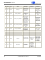
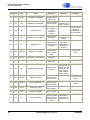
9.1 Legend ............................................................................................................................126
9.2 Error Code Interpretation ................................................................................................127
9.2.1 24-bit Error Code Interpretation ......................................................................127
9.2.2 32-bit Error Code Interpretation ......................................................................127
9.3 Error Codes Listing .........................................................................................................128
10. Glossary of Terms. . . . . . . . . . . . . . . . . . . . . . . . . . . . . . . . . . . . . . . . . . . . . . . . . . . . . . . . . . . 141
6
©Copyright 2006 Cirrus Logic, Inc.
DS651PM26
CobraNet Programmer’s Reference
Overview
1.
Overview
1.1
CobraNet Terminology
CobraNet is a technology that combines state of the art audio and communications
technologies. While each have their own terminology, the following terms are used to refer
to elements specific to CobraNet.
Audio Channel—A CobraNet digital audio channel operates with a sample rate 48 kHz
or 96 kHz and a sample size of 16, 20, or 24 bits.
Bundle—A Bundle* is the basic CobraNet audio routing element and can carry 0 to 8
audio channels. Bundles are assigned a number which determines both which interface
the Bundle is routed to and in what manner. The range within which the Bundle number
falls determines whether it is routed as a multicast, unicast, or private type. Bundles are
numbered 1 through 65535. CobraNet interfaces are capable of sending and receiving
multiple bundles simultaneously. Bundle numbers are described in more detail in Table 2.,
"Bundle Numbering" .
*Bundles were formerly referred to as channels or network channels and may be seen represented as such in some SNMP
variable names and older documentation.
CobraNet Device—A CobraNet device is any equipment containing one or more
CobraNet interfaces.
CobraNet Interface—The CobraNet interface is the hardware (or hardware design) and
software supplied by Cirrus Logic to manufacturers of CobraNet enabled equipment.
Several generations of the CobraNet interface exist and will interoperate with each other:
CS4961xx and CS1810xx - A family of CobraNet chips containing one or more
32-bit, 120-MIPS DSP cores, RAM and audio I/O circuitry.
CM-2 - A modular CobraNet interface based on a CS4961xx device.
CM-1 - A modular CobraNet interface based on a 24-bit, 100 MIPS DSP.
Silicon Series Reference Design - A CobraNet design based on the CS1810xx
or CS4961xx. This is essentially a CM-2 without the modular circuit board and
host interface connector.
24-bit Platform - CobraNet interfaces based on 24-bit DSPs: Reference design,
CM-1.
32-bit Platform - CobraNet interfaces based on 32-bit DSPs: CS4961xx and
CS1810xx, CM-2.
Reference Design - A CobraNet interface design based on a 24-bit, 40 MIPS
DSP.
Conductor—The conductor is the CobraNet interface elected to provide master clock
and transmission arbitration for the network. The role of the conductor and the means for
selecting a conductor are described elsewhere in this document. All CobraNet devices
other than the conductor operate in a performer role.
Isochronous cycle - One or more CobraNet bundles are transmitted each isochronous
cycle. The period of an isochronous cycle is 750 Hz or 1-1/3 mS
DS651PM25
©Copyright 2006 Cirrus Logic, Inc.
7
CobraNet Programmer’s Reference
Overview
Host Management Interface (HMI) - The hardware (8-bit bi-directional parallel interface)
and protocol for accessing MI variables locally. The HMI is described in detail in the
CS4961xx/CS1810xx Hardware Manual and CM-1 Hardware Manual.
Management Interface (MI) - The set of variables used to control and monitor the
CobraNet interface. MI variables are accessible both locally through the Host
Management Interface (HMI) and over the network using Simple Network Management
Protocol (SNMP). MI variables are described in detail in Section 6. "Management
Interface Variable Reference" on page 28.
Packet Bridge - A function provided by the CobraNet protocol which allows a CobraNet
interface to send and receive raw Ethernet packets over the same Ethernet media used
for audio transmission.
Performer - A CobraNet interface which receives its transmission permissions and
master clock from a conductor. In the event a conductor fails, the CobraNet protocol will
automatically promote a performer to become the new conductor.
Receiver - A logical entity within the CobraNet interface capable of receiving one Bundle.
Serial Bridge - A function provided by the CobraNet protocol which allows a CobraNet
interface to send and receive asynchronous (i.e. RS-232) data over the same Ethernet
media used for audio transmission.
Transmitter - A logical entity within the CobraNet interface capable of transmitting one
Bundle.
8
©Copyright 2006 Cirrus Logic, Inc.
DS651PM25
CobraNet Programmer’s Reference
Overview
1.2
Protocol
The CobraNet protocol operates at the Data Link Layer also referred to as OSI Layer 2 or
MAC layer. CobraNet uses four basic packet types described below. All CobraNet packets
are identified with a unique Ethernet protocol identifier (0x8819) assigned to Cirrus Logic.
As CobraNet is a Local Area Network (LAN) technology and not a Wide Area Network
(WAN) technology, CobraNet does not utilize Internet Protocol (IP) to transport audio.
Packet Bridge packets are generic packets and are not identified as CobraNet packets.
Packet bridging is discussed in more detail in Section 2.2 "Packet Bridge" on page 13.
1.2.1 Beat Packet
A multicast packet with an address of 01:60:2B:FF:FF:00 and which contains network
operating parameters, clock and transmission permissions. The beat packet is
transmitted 750 times per second from a single CobraNet device on the network (the
conductor) and indicates the start of the main isochronous cycle. Since the beat packet
carries the clock for the network, it is sensitive to delay variation. If the delay variation
specification shown in Table 1 on page 10 is not met, CobraNet devices may not be able
to lock their local sample clocks to the network clock. The beat packet is typically small
(on the order of 100 bytes) but can be large on a network with numerous active bundles.
1.2.2 Isochronous Data Packet (or Bundle)
A multicast or unicast packet. A stream of isochronous data packets carries an audio
bundle. Though the size of the packet is dependent on the number and format of the
audio channels contained in the bundle, isochronous data packets are typically large. A
bundle carrying 8 channels of 20-bit audio at 48kHz sample rate in the standard latency
mode is approximately 1300 octets.
Isochronous data packets are transmitted in response to receipt of the beat packet.
However when low-latency modes are utilized, isochronous data packets are transmitted
twice or four times per isochronous cycle. The first transmission is in response to beat
packet receipt, the other transmissions are made at evenly timed intervals thereafter.
Because CobraNet devices buffer isochronous data packets, out-of-order delivery of data
packets is acceptable as long as the packet forwarding delay specifications in Table 1 on
page 10 are not exceeded.
1.2.3 Reservation Packet
A multicast packet with an address of 01:60:2B:FF:FF:01 used by the CobraNet protocol
to allocate bandwidth and establish connections between CobraNet interfaces. CobraNet
devices transmit reservation packes as needed or typically once per second at minimum.
1.2.4 Serial Bridge Packet
A multicast or unicast packet used to bridge asynchronous serial data between CobraNet
interfaces. Serial bridging is discussed in more detail in Section 2.1 "Serial Bridge" on
page 12.
DS651PM25
©Copyright 2006 Cirrus Logic, Inc.
9
CobraNet Programmer’s Reference
Overview
1.3
Timing and Performance
CobraNet provides real-time audio delivery and requires real-time performance from the
network on which it is deployed. The best means of insuring a network will deliver the
performance required by CobraNet is to verify the design using Cirrus Logic’s CobraCAD
CobraNet modeling software (available for download at www.cirrus.com). The design
check feature in CobraCAD assures that the performance requirements shown in Table 1
are met and that the network is capable of delivering the bandwidth required to support
the modeled application.
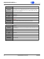
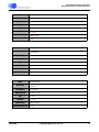
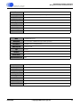
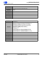
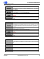
Table 1. Network Performance Requirements
Parameter
Maximum
Comments
Beat Packet Delay Variation
250µs
If delivery of beat packets periodically varies from the nominal delay by
more than this value, then the Receivers may loose sample lock or fail to
meet clock delivery specifications.
Forwarding Delay,
5-1/3ms latency
500µs
Forwarding Delay,
2-2/3ms latency
250µs
Forwarding Delay,
1-1/3ms latency a
125µs
Maximum Forwarding Delay
5000µs
Maximum Forwarding Delay Variation,
5-1/3ms latency
1000µs
Maximum Forwarding Delay Variation,
2-2/3ms latency
500µs
Maximum Forwarding Delay Variation,
1-1/3ms latency
250µs
a.
10
Forwarding delay is the sum of store forward, queuing and propagation
delays. Forwarding delay includes delay variation - i.e. 150µs forwarding
delay + 250µs delay variation = 400µs. Thus tolerance of forwarding
delay is reduced in the presence of delay variation. When forwarding
specification is exceeded, audio is delivered reliably with additional
latency. rxDelay and rxMinDelay can be used to observe and control this
adaptation to forwarding delay.
Audio cannot be delivered at any latency with extreme forwarding delays.
Delay variation exceeding these specifications will result in unreliable
audio transport due unstable rxDelay determination. In some cases this
may be addressed through manual rxMinDelay setting.
Store-forward delay on a 100Mbit Ethernet connection is 121us (assuming maximum length packets). This forwarding
delay specification is only achievable on an audio-only dedicated network. The lowest latency achievable with CobraNet on
a non-dedicated network is 1-2/3ms (using the 1-1/3ms latency mode with an rxMinDelay setting of 0x40 to make
receivers tolerant to queuing delays introduced by non-audio traffic).
©Copyright 2006 Cirrus Logic, Inc.
DS651PM25
CobraNet Programmer’s Reference
Overview
1.4
Bundle Addressing types
Multicast bundles represent a least common denominator for audio interoperability in
CobraNet networks. Bundles sent with multicast destination addresses are delivered
indiscriminately to all CobraNet interfaces and thus have the potential of overloading a
network. Care should be taken to insure that an excessive number of multicast bundles
are not used. See Bundle Assignments in CobraNet Systems (available for download at
www.cirrus.com) for a discussion of issues associated with multicast bundles.
Unicast bundles are sent to only one destination on a network. However, in the event
that more than one CobraNet interface is set to receive the same bundle number, the
CobraNet protocol may, according to rules governed by the txUniCastMode and
txMaxUnicast variables, cause unicast bundles to be sent as multicast or multi-unicast
when necessary. Multi-unicast will use unicast addressing to send up to four copies of the
same bundle to different CobraNet interfaces.The default configuration for txUnicastMode
insures that unicast bundles are never multicast.
Private bundles are a special case of unicast or multicast bundles. The transmitter's
MAC address, in addition to the bundle number, is required to fully qualify a private
channel at the receiver. Like unicast bundles, these may be either unicast or multicast
based on txUnicastMode.
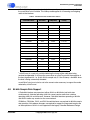
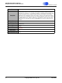
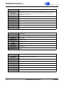
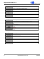
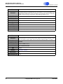
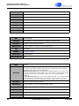
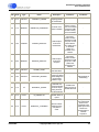
Note: Transmitted bundles must have a unique bundle number assigned to them. More
than one transmitting interface cannot use the same bundle number. Multiple receiving
interfaces can receive the same bundles.
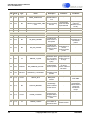
Table 2. Bundle Numbering
Hexadecimal
Decimal
Bundle
Designation
Bundle Number
Number
Transmission
Addressing
Transmission
Mode
Unused bundle. Disables
transmission/reception when
selected.
Never transmitted.
Never transmitted.
Usage
0
0
Null
1-0xFF
1-255
Multicast
Transmitted by a single
CobraNet interface and received
by any number of interfaces.
Always multicast
Always
transmitted.
Unicast
Transmitted by a single
CobraNet interface. Dependent
on txUnicastMode and
txMaxUnicast settings may be
received at a single (default
case), a few (multiple unicast
case) or a large number
(multicast case) of interfaces.
Generally unicast
but may multicast if
txUnicastMode
variable is
adjusted.
Only transmitted
when at least one
receiver is
identified via
reverse
reservation.
Private
Individual transmitters locally
allocate private channels. The
bundle number is conditioned on
the transmitter's MAC address.
There are 256 of these bundles
per transmitter thus the total
number of private bundles is
virtually unlimited as the bundle
numbers are unique to a
particular MAC address.
Generally unicast
but may multicast if
txUnicastMode
variable is
adjusted.
Only transmitted
when at least one
receiver is
identified via
reverse
reservation.
0x1000xFEFF
0xFF000xFFFF
DS651PM25
256-65279
65280-65535
©Copyright 2006 Cirrus Logic, Inc.
11
CobraNet Programmer’s Reference
Control Communications
2.
Control Communications
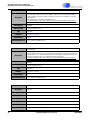
2.1
Serial Bridge
Asynchronous serial data may be bridged across the network using the serial bridge
hardware and software. The CobraNet interface has a two wire logic-level asynchronous
interface. Characters received on the interface are buffered and placed in the payload of a
special serial bridge Ethernet packet. The packet is then transmitted onto the network
with unicast or multicast addressing as configured. It is received at the destination
CobraNet interface where the data in the packet is re-serialized and presented on the
serial interface. Many standard asynchronous serial formats are supported. With proper
physical interface circuitry, this port can be made to support RS-232, RS-422 or RS-485
standards. Multi-drop two-wire interfaces are also supported.
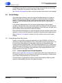
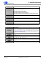
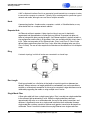
The bridging feature can be useful in a CobraNet product as either an internal or external
control interface. Used externally, the appropriate transceiver, such as an RS-232 driver
chip, is connected to the logic-level pins and in turn connected to a standard connector,
such as a DB-9 or DB-25, on the back panel. This allows control of external serial
interfaced devices remotely over Ethernet.
CobraNet
Interface
Ethernet
Network
CobraNet
Interface
RS-232
Connection
RS-485
Multi-drop
Network
Figure 2. Serial Bridging, External Application
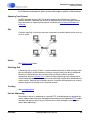
Internal application of the serial bridge allows serial communications over the network
between host processors which are incorporated into CobraNet devices. Using this
communication scheme reduces engineering effort in integrating CobraNet into audio
products that already accomplish control communications via serial link.
Microcontroller
CobraNet
Interface
Ethernet
Network
CobraNet
Interface
Microcontroller
Figure 3. Serial Bridging, Internal Application
12
©Copyright 2006 Cirrus Logic, Inc.
DS651PM25
CobraNet Programmer’s Reference
Control Communications
Although the serial bridging feature strives to transmit data at wire speed, delays are
introduced by the process of serializing, de-serializing, and prioritizing the serial bridge
packets. These delays are typically on the order of 10ms or less.
See Table 6.4.8 on page 86 for details on the MI variables used to control serial bridging.
2.2
Packet Bridge
The packet bridge provides a means for using the CobraNet interface as if it were an
Ethernet controller by providing a basic capability to send and receive raw Ethernet
packets. A CobraNet device utilizing a host processor with network stack can use this
feature to transmit and receive both control and audio data over the same network
connection.
In the simplest implementation, the host sees the packet bridge as several control
variables, a receive buffer, and a transmit buffer which are accessed via the HMI interface.
Ethernet data packets are transferred in both directions over the host port using the same
HMI semantics used to read and write other MI variables.
More advanced implementations can take advantage of interrupt and DMA modes of HMI
operation as well as some HMI operations specifically tailored to packet bridge functions.
Refer to Table 6.4.7 on page 81 for details on the MI variables used to control packet
bridging.
2.2.1 Packet Bridge Buffer Data Format
Packets are transmitted by writing raw packet data to bridgeTxPktBuffer. Packets are
received by reading bridgeRxPktBuffer. Data in both buffers shares the same format. The
first word of the buffer specifies the byte length of the data that follows. Byte length
includes the14-byte Ethernet header. The Frame Check Sequence (FCS) is automatically
appended to transmitted packets and automatically checked and stripped from received
packets. The FCS is not included in the packet data or byte length specification. Byte
length should be in the range 14 to 1514.
2.2.1.1. Processor-dependent Layout of Packet Bridge Buffers
Refer to Table 3 and Table 4 on page 14 for organization of data within bridge buffers for
24- and 32-bit platforms. All data marked as unused/0 will be received as 0 and must be
set to 0 when writing the buffer prior to transmission.
For both platforms, requested transmissions shorter than the 60-byte Ethernet packet
minimum will be padded to 60 bytes with indeterminate data.
DS651PM25
©Copyright 2006 Cirrus Logic, Inc.
13
CobraNet Programmer’s Reference
Control Communications
Table 3. Packet Bridge Buffer Layout, 24-bit Platforms
MS
Middle
Word 1 Packet byte length MS
LS
Packet byte length LS
unused/0
Word 2 Destination MAC byte 2 Destination MAC byte 3
unused/0
Word 2 Destination MAC byte 4 Destination MAC byte 3
unused/0
Word 3 Destination MAC byte 6 Destination MAC byte 5
unused/0
Word 4 Source MAC byte 2
Source MAC byte 1
unused/0
Word 5 Source MAC byte 4
Source MAC byte 3
unused/0
Word 6 Source MAC byte 6
Source MAC byte 5
unused/0
Word 7 Protocol identifier LS
Protocol identifier MS
unused/0
Word 8 Payload byte 2
Payload byte 1
unused/0
...
...
...
Word n Payload byte n
unused/0
Payload byte n-1
unused/0
2.2.1.2. 24-bit HMI Packet Bridge Buffer Data Format
Packet byte length is specified in the two MS bytes of the first word. The LS bytes will read
0 on receipt and must be set to 0 for transmit. Transmit byte length is rounded up to the
nearest even multiple of 4. Receive byte length indicates the actual number of bytes
received.
2.2.1.3. 32-bit HMI Packet Bridge Buffer Data Format
Packet data begins with the second word. Transmission order of each word is MH, MS,
LS, ML.
Table 4. Packet Bridge Buffer Layout, 32-bit Platforms
MS
Word 1 Byte length MS
MH
Byte length LS
ML
unused/0
LS
unused/0
Word 2 Destination MAC byte 2 Destination MAC byte 1 Destination MAC byte 4 Destination MAC byte 3
Word 3 Destination MAC byte 6 Destination MAC byte 5 Source MAC byte 1
Source MAC byte 2
Word 4 Source MAC byte 4
Source MAC byte 3
Source MAC byte 6
Source MAC byte 5
Word 5 Protocol identifier LS
Protocol identifier MS
Payload byte 2
Payload byte 1
Word 6 Payload byte 4
Payload byte 3
Payload byte 6
Payload byte 5
...
...
Word n Payload byte n-2
14
...
Payload byte n-3
...
Payload byte n
©Copyright 2006 Cirrus Logic, Inc.
...
Payload byte n-1
DS651PM25
CobraNet Programmer’s Reference
Control Communications
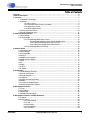
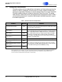
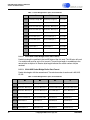
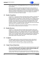
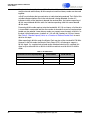
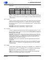
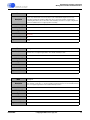
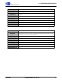
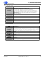
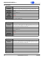
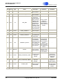
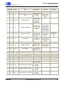
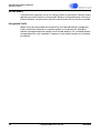
2.2.2 Packet Bridge Receive Filtering
The packet bridge can allow only selected packets to be passed to the bridge buffer or
allow copies of packets to be sent to the bridge buffer. The value of the bridgeRxFilter
variable controls the filter mode. With bridgeRxFilter = 0x10 or 0x01 the packet bridge
sends selected packets of unknown protocol to the HMI interface via the packet bridge
buffer. With bridgeRxFilter = 0x02 or 0x08, copies of selected packets are passed both to
the packet bridge and are processed by the CobraNet interface. The packet bridge never
passes audio data packets or beat packets to the host. The operation of packet bridge
filtering is shown in Figure 4 below.
Ethernet
Packet
0x10 Bridges all Packets with
Unknown Protocol
(Usually Custom Control Protocol)
CobraNet?
0x8819
N
ARP/RARP?
Y
Process
Reservation
Request
N
Process
ARP or RARP
Request
N
IP?
Process
Packet Bridge
RxPktBuffer
Y
Y
Y
Reservation
Request?
N
Packet
DestinationIP=
ipMonCurrentIP?
N
Packet Dropped
Y
Beat
Packet?
Y
Process
Beat Packet
SNMP?
Y
SNMP Agent
N
N
Serial Bridge
Packet?
Y
Process
Serial Bridge
Packet
TFTP?
Y
TFTP Server
N
N
Audio
Bundle?
Y
Process
Audio Bundle
BOOTP?
Y
BOOTP Client
N=Special
Case
0x08 Copies all IP Packets and Forwards to Host Processor
0x02 Copies Reservation Requests and Forwards to Host Processor
0x01 Bridges Special 0x8819 non-audio Packets
Figure 4. Packet Bridge Receive Filtering
The default value of BridgeRxFilter is 0x01. When BridgeRxFilter is set to 0x08 and/or
0x02, the CobraNet interface and the host processor can independently process the
same packets. The Host processor can use 0x08 in order to respond to packets with IP
addresses other than the address assigned to the CobraNet interface. Care must be
taken in the host processor software when using these modes to ensure that the
CobraNet interface and Host Processor do not both respond to the same packets.
DS651PM25
©Copyright 2006 Cirrus Logic, Inc.
15
CobraNet Programmer’s Reference
Network Stack
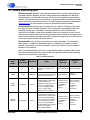
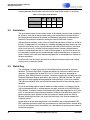
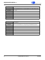
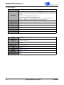
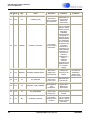
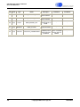
3.
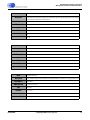
Network Stack
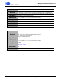
Internet Protocol Suite
CobraNet Services
Application
BOOTP
Transport
Network
SNMP
TFTP
UDP
RARP
Logical Link
Physical
ARP
ICMP
CobraNet
Audio
Serial
Bridge
Packet
Bridge
IP
802.3 Ethernet
Fast Ethernet Interface
Figure 5. CobraNet Network Stack
3.1
CobraNet Audio
This includes transmission and reception of audio data packets and reservation requests,
implementation of conductor arbitration, and the ability to serve in either conductor or
performer roles. CobraNet audio is a self-contained service that spans from Logical Link
(2) to Application (7) layers.
3.2
Serial Bridge
This service provides bridging of asynchronous serial streams over the Ethernet network.
This self-contained service spans from the logical link to the Application layer. The serial
bridge service is discussed in Section 2.1 "Serial Bridge" on page 12.
3.3
Packet Bridge
This service simply allows the CobraNet interface to operate as an Ethernet controller for
a connected host. This service works at the logical link layer and provides access to the
network without providing any actual network services. The packet bridge feature is
discussed in Section 2.2 "Packet Bridge" on page 13.
3.4
BOOTP
The boot protocol (BOOTP) is supported as specified in RFCs 951 and 1542. Network
clients use BOOTP to receive an IP address from a BOOTP server.
Clients needing an IP address will broadcast a BOOTP request packet. A BOOTP server
on the network will respond with a BOOTP response containing the preferred IP address
for the client to use. Use of BOOTP simplifies the error-prone task of assigning unique IP
addresses to devices on a large network. BOOTP is carried via UDP/IP and, as such, is
able to pass through properly configured routers.
BOOTP requests are transmitted by the CobraNet interface on a randomized schedule as
recommended in the RFCs. Requests are sent out frequently at startup and then taper
16
©Copyright 2006 Cirrus Logic, Inc.
DS651PM25
CobraNet Programmer’s Reference
Network Stack
down to an approximate 2-per-minute minimum rate. Two conditions must be met before a
CobraNet device will send out BOOTP requests:
• The device must not already have an IP address. Apart from BOOTP, there are
two other means for a CobraNet interface to obtain an IP address - RARP and
the ipMonitor variables.
• The device must be attached to a switched network. In order to avoid producing
unregulated traffic, BOOTP requests are not transmitted on a repeater network.
Upon receipt of a valid BOOTP response, a CobraNet device will change its IP address to
the IP address indicated by the BOOTP response. It is not necessary for a response to be
paired with a specific request to be considered valid.
3.5
RARP (partial support)
RFC 903 defines reverse address resolution protocol (RARP). Network clients use RARP
to receive an IP address from a central server. RARP differs from BOOTP in that it is
carried at the logical link layer (Layer 2) and thus cannot pass through IP routers.
RARP is comprised of request and response packet types. Upon receipt of a valid RARP
response packet, a CobraNet device will change its IP address to the IP address
indicated by the RARP response. The CobraNet network stack does not transmit RARP
request packets.
RARP is the means used by the CobraNet Discovery application (Disco) and CNDisco
object for IP address assignment.
3.6
ICMP (partial support)
Internet control message protocol (ICMP) is an administrative protocol defined in RFC
972.
CobraNet devices which have been assigned an IP address will respond to ICMP echo
(commonly referred to as ‘ping’) requests. No other ICMP support is implemented in the
CobraNet network stack.
3.7
ARP
Address resolution protocol (ARP) is used by the IP protocol to translate IP addresses to
MAC addresses according to RFC 826.
A host seeking a MAC address associated with an IP address broadcasts an ARP
request. The device using the specified IP address replies with an ARP response packet.
In this way the requesting host obtains the MAC address for the target device.
The CobraNet interface responds to ARP requests when appropriate. CobraNet will not
generate ARP requests. For this reason the CobraNet can only respond to IP messages
and cannot initiate IP communications.
3.8
IP
The internet protocol (IP) is defined in RFC 791. IP is a network protocol (layer 3 of the
OSI 7-layer networking model) responsible for routing of packets and segmentation and
reassembly of packets.
DS651PM25
©Copyright 2006 Cirrus Logic, Inc.
17
CobraNet Programmer’s Reference
Network Stack
The CobraNet implementation of IP has the following limitations:
• Segmentation and reassembly is not supported. Segmentation is primarily
utilized by stream based TCP protocols that can generate large data packets.
Reassembly capability can be necessary on heterogeneous networks (those
comprising multiple network technologies such as Ethernet, FDDI, and ISDN).
• Cannot initiate IP communications; can only respond to incoming messages.
The CobraNet implementation does not support net mask and default gateway
concepts required to initiate communications to other subnets. Furthermore,
CobraNet's implementation of ARP does not support generation of ARP
requests.
3.9
UDP
User datagram protocol (UDP) is defined in RFC 768. UDP is a transport protocol (layer 4
of the OSI 7-layer networking model) responsible for maintaining the integrity of data.
UDP is an extremely simple protocol which, by design, defers the data integrity problem to
application protocols in higher network layers.
CobraNet fully supports UDP.
3.10 TFTP
Trivial file transfer protocol (TFTP) is defined in RFC 783. TFTP supports file read and
write via a UDP/IP transport. The CobraNet implementation of TFTP supports only binary
reads and writes to a specific set of files. This is the mechanism used to update firmware
in a CobraNet interface. The TFTP file names correspond to the different sectors of the
FLASH memory and can differ in name and size for different revisions of CobraNet
interface hardware.
Firmware update is a complex process best accomplished by use of an encapsulated
software module, such as the PACNFirm object library, or by use of the CobraNet
Discovery program which are aware of the data structures and protocol utilized.
3.11 SNMP
Version 1 of the simple network management protocol (SNMP) is defined in RFC 1157.
The CobraNet SNMP interface is version 1 compliant.
A management information base (MIB) is associated with any SNMP implementation.
CobraNet supports the standard MIB for network devices as defined in RFC 1213 “MIB-II”
in addition to its own MIB for CobraNet-specific objects.
The CobraNet MIB file is available for public download in order to facilitate full use of the
CobraNet SNMP interface via SNMPv1 compliant applications.
18
©Copyright 2006 Cirrus Logic, Inc.
DS651PM25
CobraNet Programmer’s Reference
Audio Paths
Audio Paths
TX1
TX2
TX3
TX4
Synchronous Serial
Transmitters
TxSubMap
-
Outgoing
Audio Bundles
Audio Output Metering
1
31
audioMeterMap
audioLoopSrc
Loop Variables
2
audioLoopDst
RX4
Transmitters
audioDupSrc
RX3
0 (Silence)
1
8
16
24
32
33
40
48
56
64
audioDupDst
RX2
-
Ethernet
Dup Variables
RX1
Audio Routing
Channels
32
33
34
63
64
Audio Input Metering
RxSubMap
Up to 8 Channels Each
Up to 8 Channels Each
Synchronous
Serial Receivers
Audio Buffering
audioMap
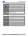
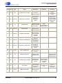
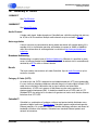
4.
-
Incoming
Audio Bundles
Receivers
Ethernet
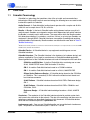
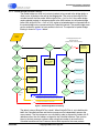
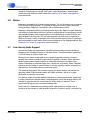
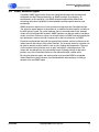
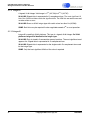
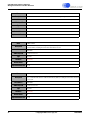
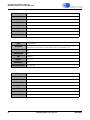
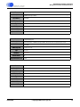
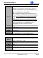
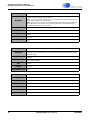
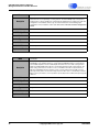
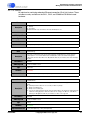
NOTES: 1. Do not alter audioMap, use txSubMap and rxSubMap to control routing to/from Bundles and SSI.
2. The number of transmitters and receivers may vary depending on the implementation.
Figure 6. CobraNet Interface Audio Model
4.1
Audio Routing Channels
There are 65 audio routing channels within a CobraNet interface numbered from 0 to 64.
Channels 1 through 32 are used to route audio from the Synchronous Serial Interface
(SSI) to the network transmitters. Channels 33 through 64 are used to route audio from
DS651PM25
©Copyright 2006 Cirrus Logic, Inc.
19
CobraNet Programmer’s Reference
Audio Paths
the network receivers to the SSI outputs. Routing channel 0 is a special logical channel
used to supply silence to a transmitted channel or serve as a “bit bucket” when receiving
from the network.
Audio arrives and leaves the interface through the SSI receivers and transmitters. As
each sample arrives it is buffered. The mapping of audio input and output channels to
audio I/O buffer offsets is fixed (and non-intuitive). To accommodate channel numbering
differences of different CobraNet devices, the audioMap variables allow a mapping from
audio I/O buffer offsets to routing channel numbers. This mapping is preset by the
manufacturer and should never need to be altered.
4.2
Bundle Transmitters
A Transmitter is a logical entity within the CobraNet interface capable of transmitting one
bundle of up to 8 audio channels. Input audio routing channels (0, 1 through 32) are
mapped into Bundles associated with a particular transmitter via the txSubMap variables
associated with that transmitter. There are 8 txSubmap variables associated with each
transmitter, each of which can be set to a particular routing channel number. The first
txSubMap variable sets the routing channel that will be transmitted in the first audio
channel in the bundle. The second txSubmap variable selects the source for the second
audio channel to be transmitted in the bundle...and so on.
Audio resolution (sample size) and sample rate (48 kHz or 96 kHz) are determined by
other transmitter parameters discussed in this document.
4.3
Bundle Receivers
A Receiver is a logical entity within the CobraNet interface capable of receiving one
bundle of up to 8 audio channels. Output audio routing channels (0, 33 through 64) are
mapped from the receiver via the rxSubMap variables. There are 8 rxSubMap variables
associated with each receiver, each of which can be set to a particular routing channel
number. The first rxSubMap variable selects the routing channel that will receive the first
audio channel in the bundle. The second rxSubMap variable specifies mapping the
second audio channel in the bundle...and so on.
4.4
Loopback
The loopback object provides a means for the interface to transfer audio channels
internally. Loopback overcomes the limitation that a device cannot receive its own
transmission and also allows the audio I/O system to be tested locally.
The audioLoopSource and audioLoopDest variables control this feature.
4.5
Output Channel Duplication
The audio routing channel mapping facilities allow a single routing channel to be mapped
to any number of audio channels in any number of network transmitters (Bundles). It is,
however, not possible to direct an audio channel in a network receiver to multiple audio
routing channels for output through multiple SSI channels or ports.
Output channel duplication allows output routing channels to be copied to other output
routing channels. This feature is implemented as a separate set of “dup” paths controlled
20
©Copyright 2006 Cirrus Logic, Inc.
DS651PM25
CobraNet Programmer’s Reference
Audio Paths
by audioDupSource and audioDupDest variables. An output can be specified as the
source for a duplication by multiple “dup” paths. Output duplication is accomplished
without incurring additional audio latency. See Section 6.4.10 "Audio" on page 92 for
more information.
4.6
Meters
Metering is provided for all 64 audio routing channels. The first 32 meters can be mapped
to the 32 input routing channels. The second 32 meters are used to meter the output
routing channels. Mapping is controlled by the audioMeterMap variable.
Metering is disabled by default to conserve processing cycles. Meters are peak detecting
with simple first-order decay ballistics. Ballistics are comprised of an instantaneous attack
and exponential decay time programmable via audioMeterDecay variable. Ballistics are
adjusted globally for all meters. All level measurements are peak level (as opposed to
RMS, for instance). Level is indicated in 24-or 32-bit positive signed values. A cumulative
peak hold element on each meter allows accurate detection of any clipping condition. See
Section 6.4.10 "Audio" on page 92 for more information.
4.7
Low-latency Audio Support
Low-latency modes are supported on CobraNet interfaces without need for hardware
changes to the CobraNet interface or CobraNet Device. The default mode of operation is
5-1/3 mS latency at 48 kHz sample rate.
Running in low-latency mode requires more processing power, implying a trade-off
between the number of channels supported and reduction of latency. Some referencedesign-based products need to operate at reduced channel count to support lower
latency. Depending on selected sample size, sample rate, and latency, newer CobraNet
interfaces may be subject to some limitation in channel capacity, number of transmitters
and receivers, and multiple unicast transmission count.
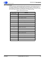
The following table shows CM-1 channel capacity for several latency and sample rate
operating modes. Eight-channel bundles with 20-bit resolution, unicast to a single
destination or multicast is assumed.
Low-latency modes also place additional demands on network performance. Specifically,
in order to achieve the desired latency, forwarding delay across the network needs to be
reduced by approximately the same factor that audio latency is reduced. These
requirements bring into play new network design rules.
Lower latency is achieved by transmitting smaller audio packets at a higher rate. A
restriction on the number of audio channels allowed in a bundle is due to a restriction on
DS651PM25
©Copyright 2006 Cirrus Logic, Inc.
21
CobraNet Programmer’s Reference
Audio Paths
the maximum size of an Ethernet packet. Therefore Lower-latency modes have relaxed
restrictions in this area. Audio channel count restrictions are summarized below.
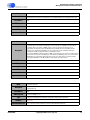
Table 5. Bundle Capacity Limits as a Function of Ethernet Packet Size
Channels per Bundle
Latency
16 bit, 48 kHz
20 bit, 48 kHz
24 bit, 48 kHz
16 bit, 96 kHz
20 bit, 96 kHz
24 bit, 96 kHz
5-1/3 ms
8
8
7
5
4
3
2-2/3 ms
8
8
8
8
8
7
1-1/3 ms
8
8
8
8
8
8
Bundle capacity or maximum channel count may be limited in some cases by both the
allowable Ethernet packet size and by the processor bandwidth required to handle lower
latency and/or higher sample rate modes. Limitations imposed by packet size are
illustrated in Table 5. Limitations imposed by additional bandwidth requirements are
discussed in the Hardware Reference Manual applicable to the particular CobraNet
Interface.
22
©Copyright 2006 Cirrus Logic, Inc.
DS651PM25
CobraNet Programmer’s Reference
Audio Paths
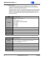
A CobraNet interface operates at a single latency and sample rate mode as specified by
the modeRateControl variable. This latency mode applies to all incoming and outgoing
audio at the interface.
Table 6. txSubFormat and rxSubFormat1 Values2
txSubFormat Value
Resolution
0
Sample Rate
Latency
No Signal
0x044000
16 bit
48 kHz
5-1/3 ms
0x054000
20 bit
48 kHz
5-1/3 ms
0x064000
24 bit
48 kHz
5-1/3 ms
0x148000
16 bit
96 kHz
5-1/3 ms
0x158000
20 bit
96 kHz
5-1/3 ms
0x168000
24 bit
96 kHz
5-1/3 ms
0x042000
16 bit
48 kHz
2-2/3 ms
0x052000
20 bit
48 kHz
2-2/3 ms
0x062000
24 bit
48 kHz
2-2/3 ms
0x144000
16 bit
96 kHz
2-2/3 ms
0x154000
20 bit
96 kHz
2-2/3 ms
0x164000
24 bit
96 kHz
2-2/3 ms
0x041000
16 bit
48 kHz
1-1/3 ms
0x051000
20 bit
48 kHz
1-1/3 ms
0x061000
24 bit
48 kHz
1-1/3 ms
0x142000
16 bit
96 kHz
1-1/3 ms
0x152000
20 bit
96 kHz
1-1/3 ms
0x162000
24 bit
96 kHz
1-1/3 ms
1
rxSubFormat is a read only variable indicating the format of the audio data being
received and decoded. It will have the same value as txSubFormat with the exception of
the least-significant bit. i.e. 16-bit, 48 kHz sample rate, 5 1/3-mS latency = 0x44001 when
the data is being successfully decoded.
2
modeRateControl must also be set to the correct value necessary to support the mode
selected by txSubFormat.
4.8
96 kHz Sample Rate Support
A CobraNet interface may operate at either 48 kHz or 96 kHz but not both rates
simultaneously. A device operating at 48 kHz cannot receive audio from a device
operating at 96 kHz and vice versa. However, CobraNet interfaces operating at 96 kHz
and 48 kHz audio may co-exist on the same network.
CS4961xx, CS1810xx, CM-2, and CM-1 based interfaces are required for 96 kHz sample
rate operation. No hardware changes are required to support the increased sample rate
on these platforms. 96 kHz is not supported in the legacy CobraNet Reference Design.
DS651PM25
©Copyright 2006 Cirrus Logic, Inc.
23
CobraNet Programmer’s Reference
Audio Paths
Sample rate is selected by the modeRateControl variable. modeRateControl selects both
sample rate and audio latency. 96 kHz sample rate and low-latency modes can be used
together.
rxSubFormat indicates the type and status of audio date being received. The LS bit of this
variable indicates whether data in the sub channel is being decoded. A value of 0
indicates inability of the interface to decode the received data. An interface operating at
48 kHz cannot decode 96 kHz audio. An interface operating at 96 kHz cannot decode
48 kHz audio.
Processing 96 kHz audio requires twice the bandwidth. At 5-1/3 ms latency, all of the data
is transmitted in one packet and thus the number of channels that can be transferred per
bundle may be reduced. Lower latency modes can support more channels at 96 kHz, as
the data is distributed across 4 packets at 1-1/3 mS and 2 packets at 2-2/3 ms latency.
See Table 5., "Bundle Capacity Limits as a Function of Ethernet Packet Size" for more
detail on this topic.
When operating in 96 kHz mode, the Master Clock remains at the standard 24.576 MHz.
However, in 96 kHz mode, the Sample Clock Output (FS1) will change to support a
96 kHz signal. If a sample clock cascade and/or reference clock input is supplied, this
signal may be either 48 kHz or 96 kHz in 96 kHz mode but must be 48 kHz in 48 kHz
mode.
Table 7. Bit Clock Rates
24
Synchronous Serial Port Operating Mode
48 kHz SCK Rate
96 kHz SCK Rate
64Fs (2 channels x 4 interfaces)
3.072 MHz
6.144 MHz
128Fs (4 channels x 4 interfaces)
6.144 MHz
12.288 MHz
256Fs (8 channels x 4 interfaces)
12.288 MHz
24.576 MHz
©Copyright 2006 Cirrus Logic, Inc.
DS651PM25
CobraNet Programmer’s Reference
Management Interface
5.
Management Interface
The Management Interface (MI) is the means by which the CobraNet interface is
controlled and monitored. Integral to the management interface are the MI variables. The
MI variables are read and written via the Host Management Interface (HMI) or remotely
over the audio network via SNMP. Both methods operate on the same common set of MI
variables. The CobraNet device is configured in real time as the variables are changed.
Variables may have read-only, read/write, or read/write-persistent attributes. All variables
are given an initial value at startup. The value of all variables can be read. Read/write and
Read/write-persistent variable types can be both read and written. The value of persistent
variables is saved in flash memory and the variable is restored at startup to the last value
written. See Section 5.2 "Persistence" on page 26 for more detail on persistent variables.
All MI variables are documented in the Section 6. "Management Interface Variable
Reference" on page 28.
MI variables fall into three classes. CobraNet-specific variables allow for configuration and
monitoring of CobraNet functionality such as audio transmission and reception. A second
class of variables known as SNMP MIB-II variables provides a uniform means of
monitoring a network device. These variables are primarily concerned with performance
and configuration of the network interface and associated protocols. A third class of
product-specific variables may exist when a manufacturer makes use of SNMP extension
agent capabilities. This third class of variables is used for controlling and monitoring
product-specific features and functions.
5.1
Flash
Flash memory may be updated via TFTP or through HMI. The HMI flash memory access
mechanism allows flash contents to be read and written via the host port. This provides
functionality for the HMI similar to that which TFTP provides via the network.
The mechanism cannot allow direct access to the flash memory. Instead a request to read
or write flash is performed by supplying the flash address (flashTAddress), byte length
(flashTLength), transfer direction (flashTDirection), and data (bridgeTxPktBuffer). The
request is then initiated by writing to flashTRequest.
The flash memory is a byte-wide device. On 24-bit CobraNet platforms, the transmit buffer
is comprised of 3-byte words. The mapping between the byte-wide flash data and the
wider buffer memory is as follows.
Table 8. Flash Layout, 24-bit Platforms
MS
DS651PM25
Middle
LS
First Word
Byte 3
Byte 2
Byte 1
Second Word
Byte 6
Byte 5
Byte 4
©Copyright 2006 Cirrus Logic, Inc.
25
CobraNet Programmer’s Reference
Management Interface
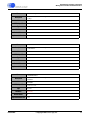
On 32-bit CobraNet platforms, the transmit buffer is comprised of 4-byte words. The
mapping between the byte-wide flash data and the wider buffer memory is as follows.
Table 9. Flash Layout, 32-bit Platforms
5.2
MS
MH
ML
LS
First Word
Byte 4
Byte 3
Byte 2
Byte 1
Second Word
Byte 8
Byte 7
Byte 6
Byte 5
Persistence
The persistence feature causes values written to Read/write-persistent type variables to
be written to flash and for these stored values to be restored during startup. With the
persistence feature disabled, Read/write and Read/write-persistent variables behave
identically. Persistence is enabled by setting the flashPersistEnable variable.
With persistence enabled, values written to Read/write-persistent variables are written to
flash by a background task according to a schedule designed to prevent excessive write
cycles on the memory and to avoid interference with other critical functions. In extreme
cases it can take up to 1 minute to store changed values. However, the persistence
feature is implemented such that it is safe to remove power at any time with the caveat
that the values recalled may not include changes made immediately prior to removal of
power. Variable values will never become corrupted due to unexpected loss of power or
network connection.
flashPersistAck can be used to ensure that variables have been stored to non-volatile
memory prior to removal of power.
5.3
Watch Dog
The watch dog is a digital signal from the CobraNet interface provided to allow fault
detection. The watch dog signal is toggled periodically by firmware to indicate normal
operation. The toggle rate may drop to as low as 5 Hz on occasion, depending on
processor load. Actual minimum, maximum, and nominal toggle rates can be found in the
Hardware Reference Manual applicable to the particular CobraNet interface.The watch
dog signal will stop toggling following detection and reporting of a fatal error condition.
The interface should be reset and re-initialized when absence of the watchdog signal is
detected.
Use of the watchdog requires external hardware and/or software. A hardware solution
may be implemented with a “microprocessor manager” chip such as the DS1236 from
Dallas/Maxim. A software solution could involve wiring the watch dog signal to an I/O port,
timer, or interrupt on the host processor and then wiring the CobraNet reset signal to a
general purpose output. Software on the host processor would monitor the interval
between watch dog transitions and assert the reset signal if the interval exceeds the
maximum period.
Implementation of the watch dog feature is not mandatory but is recommended. ESD,
EMI, and power fluctuation events are not uncommon in audio installations and the ability
to survive and recover from such conditions is a prerequisite for passing many electrical
certification programs.
26
©Copyright 2006 Cirrus Logic, Inc.
DS651PM25
CobraNet Programmer’s Reference
Management Interface
5.4
SNMP Extension Agent
CobraNet’s SNMP agent feature allows the CobraNet interface to be monitored and
configured over the Ethernet network by an SNMP manager (or managers). An
enhancement of this capability is the SNMP extension agent which allows these
monitoring and control capabilities to be extended to product-specific features and
functionality.
SNMP extensions require use of a host processor attached to the CobraNet interface.
The extension agent appears to the processor as additional product-specific variables in
the HMI memory space. For status reporting, the host microcontroller writes updated
values to the associated HMI locations. SNMP requests can then be used to read these
values at any time. Extension values can also be written via SNMP and monitored by the
host processor in order to provide a control path to the host processor via SNMP.
Extensions implemented along with the appropriate hardware and host software can be
used to control and monitor many useful functions. For example, extension variables can
be used to remotely monitor metrics such as gain, clipping and temperature. They can
also be used to control functions such as gain, noise gates, and compression. The
system will also benefit from the persistence feature, allowing settings for the entire
product, not just the CobraNet interface, to be retained through a power-cycle.
By using the extension agent, the entire product may be made SNMP manageable
without need for the host processor to be burdened with the complexity of running a
network stack and SNMP agent.
DS651PM25
©Copyright 2006 Cirrus Logic, Inc.
27
CobraNet Programmer’s Reference
Management Interface Variable Reference
6.
Management Interface Variable Reference
CobraNet interfaces are configured and monitored by reading and writing Management
Interface variables. MI variables may be accessed directly via a processor attached to the
Host Management Interface or via the network using SNMP. The method of using the HMI
is similar for all CobraNet interfaces but may require specific semantics and may have
different word sizes depending on the actual implementation. The HMI interface is
described in more detail in the Hardware Reference Manual applicable to the particular
CobraNet Interface. Following are detailed descriptions of the size, contents, and effects
of the MI variables as well as their HMI addresses and SNMP Object Identifier numbers.
All MI variables can be accessed via the HMI but some variable properties render them
inappropriate for accessing via SNMP. These exceptions are noted in the variable
descriptions where applicable.
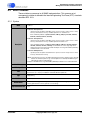
6.1
Legend
Name - Name of variable as seen in CobraNet MIB and cobrami.h header file.
Description - Description of the variable including allowed values and usage discussion.
Host Address - HMI addresses are used to access variables via the host port. HMI
addresses have a 24-bit range on both 24- and 32-bit platforms.
SNMP Object ID (OID)- The Object Identifier is the numeric name assigned to a variable
according to the SNMP protocol.
Size - Size is indicated for varying-length data types such as DisplayString and OID. Size
is not indicated for fixed types whose size is implied by their data type. Note that for fixed
types, the word size may differ depending on the processor type.
Count - Number of entries for array or buffer-type variables. Absence of a Count
specification implies a single instance variable, and thus a Count of 1.
Type - Data type of the variable. The options and format of data types are described
below in detail.
Attributes - Read-only variables can only be read and can not be modified. Read/Write
variables can be read and written. Read/Write - Persistent variables can be read and
written. If the persistence feature is enabled, values of these variables will automatically
be written to flash for recall at startup.
Default - Value assigned to the variable at startup when persistence is disabled. The
values of some Read-only variables reflect system conditions and thus may not have a
default value.
Version - Firmware version in which the variable was first introduced. Unless otherwise
noted in this field, one can assume variables will be available in the version indicated and
all subsequent versions.
28
©Copyright 2006 Cirrus Logic, Inc.
DS651PM25
CobraNet Programmer’s Reference
Management Interface Variable Reference
6.2
Data Types
6.2.1 DisplayString
A DisplayString is an ASCII string comprised entirely of printable characters.
24-bit HMI: The first word indicates the length of the string in characters. Data is stored
three characters per 24-bit word. Character order is MS, Middle, LS. For DisplayString
variables, documented Size indicates the largest possible word size of the variable. Size
includes the length field. The maximum allowable characters for a DisplayString variable
is (Size-1)×3.
32-bit HMI: The first word indicates the length of the string in characters. Data is stored
four characters per 32-bit word. Character order is MS, MH, ML, LS. For DisplayString
variables, documented Size indicates the largest possible word size of the variable. Size
includes the length field. The maximum allowable characters for a DisplayString variable
is (Size-1)×4.
6.2.2 OID
An SNMP object identifier is the numeric name of an SNMP variable. OIDs are also used
for other purposes including system-unique identifiers.
24-bit HMI: OIDs are presented in their native BER encoding. The first word indicates the
length of the encoding in bytes. Data is stored three octets per 24-bit word. Character
order is MS, Middle, LS. For OID variables documented Size indicates the largest
possible word size for the variable. Size includes the length field. The maximum number
of octets for the OID variable encoding is (Size-1)×3.
32-bit HMI: OIDs are presented in their native BER encoding. The first word indicates the
length of the encoding in bytes. Data is stored four octets per 32-bit word. Character order
is MS, MH, ML, LS. For OID variables documented Size indicates the largest possible
word size for the variable. Size includes the length field. The maximum number of octets
for the OID variable encoding is (Size-1)×4.
6.2.3 IpAddress
An IpAddress is a 32-bit internet protocol (IP) address.
24-bit HMI: Data is stored in the most-significant 16 bits of 2 consecutive 24-bit words as
shown in Table 10. The least-significant 8 bits of each location are read as zero and must
be written as zero.
Table 10. IP address Layout, 24-bit Platforms
MS
Middle
LS
Word 1
IP address byte 2
IP address byte 1
0
Word 2
IP address byte 4
IP address byte 3
0
32-bit HMI: Data is stored in a single 32-bit word as illustrated below.
Table 11. IP address Layout, 32-bit Platforms
MS
IP address byte 2
DS651PM25
MH
IP address byte 1
ML
IP address byte 4
©Copyright 2006 Cirrus Logic, Inc.
LS
IP address byte 3
29
CobraNet Programmer’s Reference
Management Interface Variable Reference
6.2.4 PhysAddress
A 48-bit Ethernet media access control (MAC) address.
24-bit HMI: Data is stored in the most-significant 16 bits of 3 consecutive memory
locations as illustrated below. The least-significant 8 bits of each location are read as zero
and must be written as zero.
Table 12. MAC address Layout, 24-bit Platforms
MS
Middle
LS
Word 1
MAC byte 2
MAC byte 1
0
Word 2
MAC byte 4
MAC byte 3
0
Word 3
MAC byte 6
MAC byte 5
0
32-bit HMI: Data is stored in two consecutive words as shown below. A third word is
unused and reserved for addressing compatibility with 24-bit platforms.
Table 13. MAC address Layout, 32-bit Platforms
MS
MH
ML
LS
Word 1
MAC byte 2
MAC byte 1
MAC byte 4
MAC byte 3
Word 2
MAC byte 6
MAC byte 5
unused
unused
Word 3
unused
unused
unused
unused
6.2.5 TimeTicks
TimeTicks is an integer encoding for time durations in units of 100ths of a second.
24-bit HMI: An unsigned timer value is available in two successive 24-bit words. A 32-bit
timer value and 15-bit fractional extension are available as shown below. The fractional
extension may be used to gain additional accuracy. It may be safely ignored for most
applications.
Table 14. TimeTicks Layout, 24-bit Platforms
MS
Middle
LS
Word 1
Timer MS
Timer MH
Timer ML
Word 2
Timer LS
Fractional LS
Fractional MS
32-bit HMI: TimeTicks value is available as two sucessive 32-bit words. A 32-bit timer
value, a 16-bit rollover, and 16-bit fractional extension are availabe as shown below. The
fractional extension may be used to gain additional accuracy. The rollover extension may
30
©Copyright 2006 Cirrus Logic, Inc.
DS651PM25
CobraNet Programmer’s Reference
Management Interface Variable Reference
be used to extend the useful range of the timer. Both may be safely ignored for most
applications.
Table 15. TimeTicks Layout, 32-bit Platforms
MS
MH
ML
LS
Word 1
Rollover MS
Rollover LS
Timer MS
Timer MH
Word 2
Timer ML
Timer LS
Fractional LS
Fractional MS
SNMP: TimeTicks is reported as a 32-bit integer in units of 100ths of a second. For
example, a reported value of 1000 indicates a 10-second timer reading. As seen through
SNMP, TimeTicks variables roll over after 232 100ths of a second (42,949,672.96 seconds
- over one year).
6.2.6 Counter
Counters are never writable and cannot be reset. They indicate the count value since the
interface was last restarted (sysUpTime = 0). Counters roll over to zero after reaching
their maximum value of 224 (16,777,216) on 24-bit platforms and 232 (4,294,967,296) on
32-bit platforms.
24-bit HMI: Counter value is represented as a single 24-bit word.
32-bit HMI: Counter value is represented as a single 32-bit word.
6.2.7 Counter2
Counter2 is specific to 24-bit platforms and is a 48-bit unsigned event counter. Counter2
rolls over after 248 counts. Counters are never writable. On 32-bit platforms Counter2 is
identical to the Counter type.
24-bit HMI: The counter value is stored in two successive memory locations. The mostsignificant word appears first. It is suggested that one read the MS word followed by LS
word followed by a second read of the MS word and verify that the MS word has not
changed during the LS read (if so, start over).
32-bit HMI: Counter value is represented in the same single 32-bit word used for the
Counter type.
SNMP: Only the least-significant 32-bits of the counter value are reported. The counter
appears to wrap at 232 and conforms to the expected behavior for the standard SNMP
Counter data type.
6.2.8 Integer
A single-precision, signed integer. Valid range is -223 (-8,388,608) to 223-1 (8,388,607) on
24-bit platforms and -231 (-2,147,483,648) to 231-1 (2,147,483,647) on 32-bit platforms.
HMI: Signed data is represented in a single word in 2's complement form.
SNMP: On 24-bit platforms, Bad Value error may be reported if the value magnitude
exceeds the 24-bit signed integer range on a set operation.
DS651PM25
©Copyright 2006 Cirrus Logic, Inc.
31
CobraNet Programmer’s Reference
Management Interface Variable Reference
6.2.9 Integer16
A signed, 16-bit integer. Valid range is -215 (-32,768) to 215-1 (32,767).
24-bit HMI: Signed data is represented in 2's complement form. The most significant 16
bits of the 24-bit host data contain the significant bits. The LS 8 bits are read as zero and
must be written as zero.
32-bit HMI: Same as 32-bit Integer type with useful values less than 216 (65,536).
SNMP: Bad Value may be reported if value magnitude exceeds 216 on a set operation.
6.2.10 Integer48
Integer48 is specific to 24-bit platforms. This type is a signed, 48-bit integer. On 32-bit
platforms Integer48 is identical to the Integer type.
24-bit HMI: Data is stored in 2 consecutive memory locations. The most significant word
appears first. Signed data is represented in 2's complement form.
32-bit HMI: Signed data is represented as the single word in 2's complement form used
for the Integer type.
SNMP: Only the least-significant 32-bits of the value is reported.
32
©Copyright 2006 Cirrus Logic, Inc.
DS651PM25
CobraNet Programmer’s Reference
Management Interface Variable Reference
6.3
MIB-II Variables
These variables are common to all SNMP implementations. This common set of
management variables is defined in the Internet Engineering Task Force (IETF) standards
document RFC 1213.
6.3.1 System
Name
sysDescr
Describes type of interface as ASCII text.
Format for 24-bit platforms:
<product specific description> CobraNet version <protocol version>.<major version>.<minor
version>[.<manufacturer version>] <hardware platform> rev <hardware rev>
where <hardware platform> is {Referlo, Referhi, CM-1(a), CM-1(m), CS18100, CS18101,
CS18102, CS18110, CS18111, CS18112}
Format for 32-bit platforms:
<product specific description> CobraNet version <protocol version>.<major version>.<minor
version>[.<manufacturer version>] <hardware platform><hardware rev>
where <hardware platform> is {Referlo, Referhi, CM-1(a), CM-1(m), CS18100, CS18101,
CS18102, CS18110, CS18111, CS18112} and <hardware rev> is the single digit revision
number that is part of the Cirrus part number. Example: Cirrus Logic EV-2/CM-2 (CM18101)
CobraNet version 2.10.4 CS181012
Description
Format for RAVE platforms:
<product specific description> CobraNet version <protocol version>.<major version>.<minor
version>[.<manufacturer version>]
NOTE: [.<manufacturer version>] is an additional manufacturer-specific string that can be optionally
added to the firmware by Cirrus Logic for 24-bit platforms or added by the OEM using the
CNCustom program for 32-bit platforms.
Eaxmple for CS18101: Cirrus Logic EV-2/CM-2 (CM18101) CobraNet version 2.10.5 CS181012
Host Address
SNMP Object ID
1.3.6.1.2.1.1.1
Size
84 characters (28 * 3 bytes) for 24-bit platforms. Length was 21 words in 2.9.10. It is now 27 words.
84 characters (21 * 4 bytes) for CS4961xx- and CS1810xx-based platforms.
Type
DisplayString
Attributes
Default Value
Implemented Version
DS651PM25
0x100000
Read-only
“[manufacturer name] [product name] CobraNet firmware [protocol version].[major version].[minor
version].[manufacturer's version (optional, see note above)]”
2.6.3
©Copyright 2006 Cirrus Logic, Inc.
33
CobraNet Programmer’s Reference
Management Interface Variable Reference
Name
Description
Host Address
The vendor's authoritative identification of the network management subsystem contained in the
entity. This value is allocated within the SMI enterprise sub-tree (1.3.6.1.4.1) and provides an easy
and unambiguous means for determining `what kind of box' is being managed. For example, if
vendor `Cirrus Logic' was assigned the sub-tree 1.3.6.1.4.1.2680, the identifier `CM-2' could be
assigned to 1.3.6.1.4.1.2680.1.2.1.1
0x100100
SNMP Object ID
1.3.6.1.2.1.1.2
Size
60 characters
Type
OID
Attributes
Default Value
Implemented Version
Name
Description
Host Address
Read-only
1.3.6.1.4.1.2680.1.2.(CobraNet manufacturer ID).(manufacturer product ID)
2.6.3
sysContact
The identification of the contact person for this managed node, together with information on how to
contact this person.
0x100200
SNMP Object ID
1.3.6.1.2.1.1.4
Size
60 characters
Type
DisplayString
Attributes
Default Value
Implemented Version
34
sysObjectID
Read/write - Persistent
Zero length string
2.6.3
©Copyright 2006 Cirrus Logic, Inc.
DS651PM25
CobraNet Programmer’s Reference
Management Interface Variable Reference
Name
Description
Host Address
sysName
A name assigned to this managed node. By convention, this is the node's fully qualified domain
name.
0x100300
SNMP Object ID
1.3.6.1.2.1.1.5
Size
60 characters
Type
DisplayString
Attributes
Default Value
Implemented Version
Name
Description
Host Address
Read/write - Persistent
Product specific
2.6.3
sysLocation
The physical location of this node (e.g., “telephone closet, 3rd floor”)
0x100400
SNMP Object ID
1.3.6.1.2.1.1.6
Size
60 characters
Type
DisplayString
Attributes
Default Value
Implemented Version
Name
Description
Host Address
SNMP Object ID
Zero length string
2.6.3
sysUpTime
Time in 100ths of a second since the network management portion of the system was last reinitialized.
0x100500
1.3.6.1.2.1.1.3
Type
TimeTicks
Attributes
Read-only
Default Value
Implemented Version
DS651PM25
Read/write - Persistent
0
2.6.3
©Copyright 2006 Cirrus Logic, Inc.
35
CobraNet Programmer’s Reference
Management Interface Variable Reference
Name
Description
Host Address
SNMP Object ID
Type
Attributes
Default Value
Implemented Version
36
sysServices
A value which indicates the set of services supported by this entity. The value is a sum. This sum
initially takes the value zero, For each layer, L, in the range 1 through 7, that this node performs
transactions for, 2 raised to (L - 1) is added. For example, a node which performs primarily routing
functions would have a value of 4 which is equal to (2^(3-1)). A node which is a host offering
application services would have a value of 72 or (2^(4-1) + 2^(7-1)). In the context of the Internet
suite of protocols, the following service layers are commonly supported: 1 physical (e.g., repeaters),
2 datalink/subnetwork (e.g., bridges), 3 internet (e.g., IP gateways), 4 end-to-end (e.g., IP hosts), 7
applications (e.g., mail relays). For systems including OSI protocols, layers 5 and 6 may also be
counted.
0x100502
1.3.6.1.2.1.1.7
Integer
Read-only
72
2.6.3
©Copyright 2006 Cirrus Logic, Inc.
DS651PM25
CobraNet Programmer’s Reference
Management Interface Variable Reference
6.3.2 Interface
Name
Description
Host Address
SNMP Object ID
Type
Attributes
Default Value
Implemented Version
Name
Description
Host Address
SNMP Object ID
ifNumber
The number of network interfaces (regardless of their current state) present on this system.
0x110000
1.3.6.1.2.1.2.1
Integer
Read-only
1
2.1.0
ifDescr
A string containing information about the interface. This string should include the name of the
manufacturer, the product name and the version of the hardware interface.
0x110001
1.3.6.1.2.1.2.2.1.2
Size
Up to 60 characters.
Type
DisplayString
Attributes
Read-only
Default Value
“CobraNet”
Implemented Version
2.1.0
Name
ifType
Description
Host Address
SNMP Object ID
Type
Attributes
Default Value
Implemented Version
DS651PM25
The type of interface, distinguished according to the physical/link protocol(s) immediately `below'
the network layer in the protocol stack. Reference RFC 1213 for all type identifiers
0x11000A
1.3.6.1.2.1.2.2.1.3
Integer
Read-only
7
2.1.0
©Copyright 2006 Cirrus Logic, Inc.
37
CobraNet Programmer’s Reference
Management Interface Variable Reference
Name
Description
Host Address
SNMP Object ID
Type
Attributes
The size of the largest datagram or ‘packet’ that can be sent/received by the interface, specified in
octets. For interfaces that are used for transmitting network datagrams, this is the size of the largest
network datagram that can be sent on the interface.
0x11000B
1.3.6.1.2.1.2.2.1.4
Integer
Read-only
Default Value
1500
Implemented Version
2.1.0
Name
Description
Host Address
SNMP Object ID
ifSpeed
An estimate of the interface's current bandwidth in bits per second or Mbits per second (see Notes
below). For interfaces which do not vary in bandwidth or for those where no accurate estimation can
be made, this object should contain the nominal bandwidth.
0x11000C
1.3.6.1.2.1.2.2.1.5
Type
Gauge32
Attributes
Read-only
Default Value
Implemented Version
100
2.1.0, corrected is 2.6.5 (see Notes below)
Notes
Prior to CobraNet firmware version 2.6.5, ifSpeed was incorrectly reported via SNNP in Mbit/second
units (100Mbit interface ifSpeed reported as “100”). 2.6.5 correctly reports ifSpeed in bits per
second units via SNMP but due to space constraints, ifSpeed is still reported in Mbit per second
units via HMI on 24-bit platforms. ifSpeed is reported consistently in bits per second units on 32-bit
platforms.
Name
ifPhysAddress
Description
Host Address
SNMP Object ID
Type
Attributes
38
ifMtu
The interface's address at the protocol layer immediately `below' the network layer in the protocol
stack.
0x11000D
1.3.6.1.2.1.2.2.1.6
PhysAddress
Read-only
Default Value
n.a.
Implemented Version
2.1.0
©Copyright 2006 Cirrus Logic, Inc.
DS651PM25
CobraNet Programmer’s Reference
Management Interface Variable Reference
Name
Description
Host Address
SNMP Object ID
Type
Attributes
Default Value
Implemented Version
Name
Description
Host Address
SNMP Object ID
Type
Attributes
Default Value
Implemented Version
Name
Description
Host Address
SNMP Object ID
ifAdminStatus
The desired state of the interface. The testing(3) state indicates that no operational packets can be
passed
up(1) -- ready to pass packets
down(0)
0x111000
1.3.6.1.2.1.2.2.1.7
Integer
Read/Write
1
2.1.0
ifOperStatus
The current operational state of the interface. The testing(3) state indicates that no operational
packets can be passed.
up(1) - ready to pass packets
down(0)
0x112000
1.3.6.1.2.1.2.2.1.8
Integer
Read-only
1
2.1.0
ifLastChange
The value of sysUpTime at the time the interface entered its current operational state. If the current
state was entered prior to the last re- initialization of the local network management subsystem,
then this object contains a zero value.
0x112001
1.3.6.1.2.1.2.2.1.9
Type
TimeTicks
Attributes
Read-only
Default Value
n.a.
Implemented Version
2.1.0
DS651PM25
©Copyright 2006 Cirrus Logic, Inc.
39
CobraNet Programmer’s Reference
Management Interface Variable Reference
Name
Description
Host Address
SNMP Object ID
The total number of octets received on the interface, including framing characters.
0x112016
1.3.6.1.2.1.2.2.1.10
Type
Counter48
Attributes
Read-only
Default Value
Implemented Version
Name
Description
Host Address
SNMP Object ID
Type
Attributes
Default Value
Implemented Version
Name
Description
Host Address
SNMP Object ID
Type
Attributes
Default Value
Implemented Version
40
ifInOctets
0
2.1.0
ifInUcastPkts
The number of subnetwork-unicast packets delivered to a higher-layer protocol.
0x112018
1.3.6.1.2.1.2.2.1.11
Counter
Read-only
0
2.1.0
ifInNUcastPkts
The number of non-unicast (i.e., subnetwork- broadcast or subnetwork-multicast) packets delivered
to a higher-layer protocol.
0x112019
1.3.6.1.2.1.2.2.1.12
Counter
Read-only
0
2.1.0
©Copyright 2006 Cirrus Logic, Inc.
DS651PM25
CobraNet Programmer’s Reference
Management Interface Variable Reference
Name
Description
Host Address
SNMP Object ID
Type
Attributes
Default Value
Implemented Version
Name
Description
Host Address
SNMP Object ID
Type
Attributes
Default Value
Implemented Version
Name
Description
Host Address
SNMP Object ID
Type
Attributes
Default Value
Implemented Version
DS651PM25
ifInDiscards
The number of inbound packets which were chosen to be discarded even though no errors had
been detected to prevent their delivery to a higher-layer protocol. One possible reason for discarding
such a packet could be lack of buffer space.
0x11201A
1.3.6.1.2.1.2.2.1.13
Counter
Read-only
0
2.1.0
ifInErrors
The number of inbound packets that contained errors preventing delivery to a higher-layer protocol.
0x11201B
1.3.6.1.2.1.2.2.1.14
Counter
Read-only
0
2.1.0
ifInUnknownProtos
The number of packets received which were discarded due to an unknown or unsupported protocol.
0x11201C
1.3.6.1.2.1.2.2.1.15
Counter
Read-only
0
2.1.0
©Copyright 2006 Cirrus Logic, Inc.
41
CobraNet Programmer’s Reference
Management Interface Variable Reference
Name
Description
Host Address
SNMP Object ID
The total number of octets transmitted by the interface, including framing characters.
0x11201D - 0x11201E
1.3.6.1.2.1.2.2.1.16
Type
Counter48
Attributes
Read-only
Default Value
Implemented Version
Name
Description
Host Address
SNMP Object ID
Type
Attributes
Default Value
Implemented Version
Name
Description
Host Address
SNMP Object ID
Type
Attributes
Default Value
Implemented Version
42
ifOutOctets
0
2.1.0
ifOutUcastPkts
The total number of packets that higher-level protocols requested be transmitted to a subnetworkunicast address, including those that were discarded or not sent.
0x11201F
1.3.6.1.2.1.2.2.1.17
Counter
Read-only
0
2.1.0
ifOutNUcastPkts
The total number of packets that higher-level protocols requested be transmitted to a non- unicast
(i.e., a subnetwork-broadcast or subnetwork-multicast) address, including those that were discarded
or not sent.
0x112020
1.3.6.1.2.1.2.2.1.18
Counter
Read-only
0
2.1.0
©Copyright 2006 Cirrus Logic, Inc.
DS651PM25
CobraNet Programmer’s Reference
Management Interface Variable Reference
Name
Description
Host Address
SNMP Object ID
Type
Attributes
Default Value
Implemented Version
Name
Description
Host Address
SNMP Object ID
Type
Attributes
Default Value
Implemented Version
Name
Description
Host Address
SNMP Object ID
Type
Attributes
ifOutDiscards
The number of outbound packets which were chosen to be discarded even though no errors had
been detected to prevent their transmission. One possible reason for discarding such a packet could
be to free up buffer space.
0x112021
1.3.6.1.2.1.2.2.1.19
Counter
Read-only
0
2.1.0
ifOutErrors
The number of outbound packets that could not be transmitted due to errors.
0x112022
1.3.6.1.2.1.2.2.1.20
Counter
Read-only
0
2.1.0
ifOutQLen
The length of the output packet queue (in packets)
0x112023
1.3.6.1.2.1.2.2.1.21
Integer
Read-only
Default Value
n.a.
Implemented Version
2.6.1
DS651PM25
©Copyright 2006 Cirrus Logic, Inc.
43
CobraNet Programmer’s Reference
Management Interface Variable Reference
Name
Description
Host Address
SNMP Object ID
A reference to MIB definitions specific to the particular media being used to implement the interface.
For example, if the interface is implemented by Ethernet, then the value of this object refers to a
document defining objects specific to Ethernet. If this information is not present, its value should be
set to the OBJECT IDENTIFIER { 0 0 }, which is a syntactically valid object identifier, and any
conformant implementation of ASN.1 and BER must be able to generate and recognize this value.
0x112024
1.3.6.1.2.1.2.2.1.22
Size
2
Type
OID
Attributes
Default Value
Implemented Version
44
ifSpecific
Read-only
0.0
2.6.1
©Copyright 2006 Cirrus Logic, Inc.
DS651PM25
CobraNet Programmer’s Reference
Management Interface Variable Reference
6.3.3 Address Translation
The Address Translations are deprecated. These variables are no longer available via
SNMP.
Name
Description
Host Address
SNMP Object ID
Type
Attributes
Default Value
Implemented Version
Name
Description
Host Address
SNMP Object ID
Type
Attributes
Default Value
Implemented Version
Name
Description
Host Address
SNMP Object ID
The interface on which this entry's equivalence is effective. The interface identified by a particular
value of this index is the same interface as identified by the same value of ifIndex.
0x120000
Not available via SNMP
Integer
Read-only
1
2.1.0
atPhysAddress
MAC address of the device. Use of ifPhysAddress is preferred for determining the MAC address.
0x120001
Not available via SNMP
PhysAddress
Read-only
As assigned by manufacturer
2.1.0
atNetAddress
IP address of the device. Obtaining the IP address via SNMP should not be a necessary operation you need to know the IP address in order to send the query. Via HMI, the IP address may be
monitored and manipulated via the IP Monitor variables.
0x120004
Not available via SNMP
Type
IpAddress
Attributes
Read-only
Default Value
Implemented Version
DS651PM25
atIfIndex
As assigned by RARP, BOOTP or IP monitor variables.
2.1.0
©Copyright 2006 Cirrus Logic, Inc.
45
CobraNet Programmer’s Reference
Management Interface Variable Reference
6.3.4 IP
Name
Description
Host Address
SNMP Object ID
Type
Attributes
Default Value
Implemented Version
Name
Description
Host Address
SNMP Object ID
Type
Attributes
The indication of whether this entity is acting as an IP gateway to forward of datagrams received by,
but not addressed to, this entity. IP gateways forward datagrams. IP hosts do not (except those
source-routed via the host).
0x130000
1.3.6.1.2.1.4.1
Integer
Read/Write
Always reads 2
2.6.0
ipDefaultTTL
The default value inserted into the Time-To-Live field of the IP header of datagrams originated at
this entity when a TTL value is not supplied by the transport layer protocol.
0x130001
1.3.6.1.2.1.4.2
Integer
Read/Write
Default Value
128
Implemented Version
2.6.0
Name
Description
Host Address
SNMP Object ID
Type
Attributes
Default Value
Implemented Version
46
ipForwarding
ipInReceives
The total number of input datagrams received, including those received in error.
0x131000
1.3.6.1.2.1.4.3
Counter
Read-only
0
2.6.0
©Copyright 2006 Cirrus Logic, Inc.
DS651PM25
CobraNet Programmer’s Reference
Management Interface Variable Reference
Name
Description
Host Address
SNMP Object ID
Type
Attributes
Default Value
Implemented Version
Name
Description
Host Address
SNMP Object ID
Type
Attributes
Default Value
Implemented Version
Name
Description
Host Address
SNMP Object ID
Type
Attributes
Default Value
Implemented Version
DS651PM25
ipInHdrErrors
The number of input datagrams discarded due to errors in their IP headers, including bad
checksums, version number mismatch, other format errors, time-to-live exceeded, errors discovered
in processing their IP options, etc.
0x131001
1.3.6.1.2.1.4.4
Counter
Read-only
0
2.6.0
ipInAddrErrors
The number of input datagrams discarded because the IP address in the IP header's destination
field was not a valid address to be received at this entity. This count includes invalid addresses (e.g.,
0.0.0.0) and addresses of unsupported Classes (e.g., Class E). For entities which are not IP
Gateways and therefore do not forward datagrams, this counter includes datagrams discarded
because the destination address was not a local address.
0x131002
1.3.6.1.2.1.4.5
Counter
Read-only
0
2.6.0
ipForwDatagrams
The number of input datagrams for which this entity was not the final IP destination, as a result of
which an attempt was made to find a route to forward them to the final destination. In entities which
do not act as IP Gateways, this counter will include only those packets which were Source-Routed
via this entity, and the Source- Route option processing was successful.
Not available
1.3.6.1.2.1.4.6
Counter
Read-only
0
2.6.0
©Copyright 2006 Cirrus Logic, Inc.
47
CobraNet Programmer’s Reference
Management Interface Variable Reference
Name
Description
Host Address
SNMP Object ID
Type
Attributes
Default Value
Implemented Version
Name
Description
Host Address
SNMP Object ID
Type
Attributes
Default Value
Implemented Version
Name
Description
Host Address
SNMP Object ID
Type
Attributes
Default Value
Implemented Version
48
ipInUnknownProtos
The number of locally-addressed datagrams received successfully but discarded because of an
unknown or unsupported protocol.
0x131003
1.3.6.1.2.1.4.7
Counter
Read-only
0
2.6.0
ipInDiscards
The number of IP datagrams received successfully but which were discarded (e.g., for lack of buffer
space). Note that this counter does not include datagrams discarded while awaiting re-assembly.
0x131004
1.3.6.1.2.1.4.8
Counter
Read-only
0
2.6.0
ipInDelivers
The total number of input datagrams successfully delivered to IP user-protocols (including ICMP)
0x131005
1.3.6.1.2.1.4.9
Counter
Read-only
0
2.6.0
©Copyright 2006 Cirrus Logic, Inc.
DS651PM25
CobraNet Programmer’s Reference
Management Interface Variable Reference
Name
Description
Host Address
SNMP Object ID
Type
Attributes
Default Value
Implemented Version
Name
Description
Host Address
SNMP Object ID
Type
Attributes
Default Value
Implemented Version
Name
Description
Host Address
SNMP Object ID
Type
Attributes
Default Value
Implemented Version
DS651PM25
ipOutRequests
The total number of IP datagrams which local IP user-protocols (including ICMP) supplied to IP in
requests for transmission. Note that this does not include datagrams counted in ipForwDatagrams.
0x131006
1.3.6.1.2.1.4.10
Counter
Read-only
0
2.6.0
ipOutDiscards
The number of IP datagrams for which no problem existed to prevent their transmission, but which
were discarded (e.g., for lack of buffer space). Note that this counter would include datagrams
counted in ipForwDatagrams if any such packets met this (discretionary) discard criterion.
Not available
1.3.6.1.2.1.4.11
Counter
Read-only
0
2.6.0
ipOutNoRoutes
The number of IP datagrams discarded because no route could be found to transmit them to their
destination. Note that this counter includes packets counted in ipForwDatagrams which meet this
`no-route' criterion. This includes any datagrams which cannot route because all of its default
gateways are down.
Not available
1.3.6.1.2.1.4.12
Counter
Read-only
0
2.6.0
©Copyright 2006 Cirrus Logic, Inc.
49
CobraNet Programmer’s Reference
Management Interface Variable Reference
Name
Description
Host Address
SNMP Object ID
Type
Attributes
Default Value
Implemented Version
Name
Description
Host Address
SNMP Object ID
Type
Attributes
Default Value
Implemented Version
Name
Description
Host Address
SNMP Object ID
Type
Attributes
Default Value
Implemented Version
50
ipReasmTimeout
The maximum number of seconds which received fragments are held while they are awaiting
reassembly.
Not available
1.3.6.1.2.1.4.13
Integer
Read-only
0
2.6.0
ipReasmReqds
The number of IP fragments received which needed to be reassembled.
0x131007
1.3.6.1.2.1.4.14
Counter
Read-only
0
2.6.0
ipReasmOKs
The number of IP datagrams successfully re-assembled.
Not available
1.3.6.1.2.1.4.15
Counter
Read-only
0
2.6.0
©Copyright 2006 Cirrus Logic, Inc.
DS651PM25
CobraNet Programmer’s Reference
Management Interface Variable Reference
Name
Description
Host Address
SNMP Object ID
Type
Attributes
Default Value
Implemented Version
Name
Description
Host Address
SNMP Object ID
Type
Attributes
Default Value
Implemented Version
Name
Description
Host Address
SNMP Object ID
Type
Attributes
Default Value
Implemented Version
DS651PM25
ipReasmFails
The number of failures detected by the IP re- assembly algorithm (for whatever reason: timed out,
errors, etc). Note that this is not necessarily a count of discarded IP fragments since some
algorithms (notably the algorithm in RFC 815) can lose track of the number of fragments by
combining them as they are received. This value will always increment on receipt of a fragmented
packet as CobraNet does not support packet re-assembly
0x131007 (same as ipReasmReqds)
1.3.6.1.2.1.4.16
Counter
Read-only
0
2.6.0
ipFragOKs
The number of IP datagrams that have been successfully fragmented at this entity. The CobraNet
interface does not support fragmentation. This variable will always read 0.
Not available
1.3.6.1.2.1.4.17
Counter
Read-only
0
2.6.0
ipFragFails
The number of IP datagrams that have been discarded because they needed to be fragmented at
this entity but could not be, e.g., because their Don't Fragment flag was set. The CobraNet interface
does not support fragmentation. This variable will always read 0.
Not available
1.3.6.1.2.1.4.18
Counter
Read-only
0
2.6.0
©Copyright 2006 Cirrus Logic, Inc.
51
CobraNet Programmer’s Reference
Management Interface Variable Reference
Name
Description
Host Address
SNMP Object ID
Type
Attributes
Default Value
Implemented Version
Name
Description
Host Address
SNMP Object ID
Type
Attributes
Default Value
Implemented Version
52
ipFragCreates
The number of IP datagram fragments that have been generated as a result of fragmentation at this
entity. The CobraNet interface does not support fragmentation. This variable will always read 0.
Not available
1.3.6.1.2.1.4.19
Counter
Read-only
0
2.6.0
ipRoutingDiscards
The number of routing entries which were chosen to be discarded even though they are valid. One
possible reason for discarding such an entry could be to free-up buffer space for other routing
entries. The CobraNet interface does not support routing. This variable will always read 0.
Not available
1.3.6.1.2.1.4.23
Counter
Read-only
0
2.6.0
©Copyright 2006 Cirrus Logic, Inc.
DS651PM25
CobraNet Programmer’s Reference
Management Interface Variable Reference
6.3.5 UDP
Name
Description
Host Address
SNMP Object ID
Type
Attributes
Default Value
Implemented Version
Name
Description
Host Address
SNMP Object ID
Type
Attributes
Default Value
Implemented Version
Name
Description
Host Address
SNMP Object ID
Type
Attributes
Default Value
Implemented Version
DS651PM25
udpInDatagrams
The total number of UDP datagrams delivered to UDP users.
0x140000
1.3.6.1.2.1.7.1
Counter
Read-only
0
2.6.0
udpNoPorts
The total number of received UDP datagrams for which there was no application at the destination
port.
0x140001
1.3.6.1.2.1.7.2
Counter
Read-only
0
2.6.0
udpInErrors
The number of received UDP datagrams that could not be delivered for reasons other than lack of
an application at the destination port.
0x140002
1.3.6.1.2.1.7.3
Counter
Read-only
0
2.6.0
©Copyright 2006 Cirrus Logic, Inc.
53
CobraNet Programmer’s Reference
Management Interface Variable Reference
Name
Description
Host Address
SNMP Object ID
Type
Attributes
Default Value
Implemented Version
Name
Description
The total number of UDP datagrams sent from this entity.
0x140003
1.3.6.1.2.1.7.4
Counter
Read-only
0
2.6.0
udpLocalAddress
The local IP address for this UDP listener. In the case of a UDP listener which is willing to accept
datagrams for any IP interface associated with the node, the value 0.0.0.0 is used.
Host Address
N.A.
SNMP Object ID
N.A.
Type
IpAddress
Attributes
Read-only
Default Value
N.A.
Implemented Version
Not supported
Name
udpLocalPort
Description
The local port number for this UDP listener.
Host Address
N.A.
SNMP Object ID
N.A.
Type
Integer16
Attributes
Read-only
Default Value
Implemented Version
54
udpOutDatagrams
N.A.
Not supported
©Copyright 2006 Cirrus Logic, Inc.
DS651PM25
CobraNet Programmer’s Reference
Management Interface Variable Reference
6.3.6 SNMP
Name
Description
Host Address
SNMP Object ID
Type
Attributes
Default Value
Implemented Version
Name
Description
Host Address
SNMP Object ID
Type
Attributes
Default Value
Implemented Version
Name
Description
Host Address
SNMP Object ID
Type
Attributes
Default Value
Implemented Version
DS651PM25
snmpInPkts
The total number of SNMP Messages received from the transport service
0x150000
1.3.6.1.2.1.11.1
Counter
Read-only
0
2.6.0
snmpOutPkts
The total number of SNMP Messages passed to the transport service.
0x150001
1.3.6.1.2.1.11.2
Counter
Read-only
0
2.6.0
snmpInBadVersions
The total number of SNMP Messages received which were for an unsupported SNMP version.
0x150002
1.3.6.1.2.1.11.3
Counter
Read-only
0
2.6.0
©Copyright 2006 Cirrus Logic, Inc.
55
CobraNet Programmer’s Reference
Management Interface Variable Reference
Name
Description
Host Address
SNMP Object ID
Type
Attributes
Default Value
Implemented Version
Name
Description
Host Address
SNMP Object ID
Type
Attributes
Default Value
Implemented Version
Name
Description
Host Address
SNMP Object ID
Type
Attributes
Default Value
Implemented Version
56
snmpInBadCommunityNames
The total number of SNMP Messages received which used an unknown community name.
0x150003
1.3.6.1.2.1.11.4
Counter
Read-only
0
2.6.0
snmpInBadCommunityUses
The total number of SNMP Messages received for which an operation was not allowed by the
SNMP community named in the Message.
0x150004
1.3.6.1.2.1.11.5
Counter
Read-only
0
2.6.0
snmpInASNParseErrs
The total number of ASN.1 or BER errors encountered when decoding received SNMP Messages.
0x150005
1.3.6.1.2.1.11.6
Counter
Read-only
0
2.6.0
©Copyright 2006 Cirrus Logic, Inc.
DS651PM25
CobraNet Programmer’s Reference
Management Interface Variable Reference
Name
Description
Host Address
SNMP Object ID
Type
Attributes
Default Value
Implemented Version
Name
Description
Host Address
SNMP Object ID
Type
Attributes
Default Value
Implemented Version
Name
Description
Host Address
SNMP Object ID
Type
Attributes
Default Value
Implemented Version
DS651PM25
snmpInTooBigs
The total number of SNMP PDUs received for which the value of the error-status field was `tooBig'.
Not available
1.3.6.1.2.1.11.8
Counter
Read-only
Always reads 0
2.6.0
snmpInNoSuchNames
The total number of SNMP PDUs received for which the value of the error-status field was
`noSuchName'.
Not available
1.3.6.1.2.1.11.9
Counter
Read-only
Always reads 0
2.6.0
snmpInBadValues
The total number of SNMP PDUs received for which the value of the error-status field was
`badValue'.
Not available
1.3.6.1.2.1.11.10
Counter
Read-only
Always reads 0
2.6.0
©Copyright 2006 Cirrus Logic, Inc.
57
CobraNet Programmer’s Reference
Management Interface Variable Reference
Name
Description
Host Address
SNMP Object ID
Type
Attributes
Default Value
Implemented Version
Name
Description
Host Address
SNMP Object ID
Type
Attributes
Default Value
Implemented Version
Name
Description
Host Address
SNMP Object ID
Type
Attributes
Default Value
Implemented Version
58
snmpInReadOnlys
The total number of valid SNMP PDUs received for which the value of the error-status field was
`readOnly'. Note that it is a protocol error to generate an SNMP PDU which contains the value
`readOnly' in the error-status field. This object is provided as a means of detecting incorrect
implementations of SNMP.
Not available
1.3.6.1.2.1.11.11
Counter
Read-only
Always reads 0
2.6.0
snmpInGenErrs
The total number of SNMP PDUs received for which the value of the error-status field was `genErr'.
Not Available
1.3.6.1.2.1.11.12
Counter
Read-only
Always reads 0
2.6.0
snmpInTotalReqVars
The total number of MIB objects which have been retrieved successfully as a result of receiving
valid SNMP Get-Request and Get-Next PDUs.
0x150006
1.3.6.1.2.1.11.13
Counter
Read-only
0
2.6.0
©Copyright 2006 Cirrus Logic, Inc.
DS651PM25
CobraNet Programmer’s Reference
Management Interface Variable Reference
Name
Description
Host Address
SNMP Object ID
Type
Attributes
Default Value
Implemented Version
Name
Description
Host Address
SNMP Object ID
Type
Attributes
Default Value
Implemented Version
Name
Description
Host Address
SNMP Object ID
Type
Attributes
Default Value
Implemented Version
DS651PM25
snmpInTotalSetVars
The total number of MIB objects which have been altered successfully as a result of receiving valid
SNMP Set-Request PDUs.
0x150007
1.3.6.1.2.1.11.14
Counter
Read-only
0
2.6.0
snmpInGetRequests
The total number of SNMP Get-Request PDUs which have been accepted and processed.
0x150008
1.3.6.1.2.1.11.15
Counter
Read-only
0
2.6.0
snmpInGetNexts
The total number of SNMP Get-Next PDUs which have been accepted and processed.
0x150009
1.3.6.1.2.1.11.16
Counter
Read-only
0
2.6.3
©Copyright 2006 Cirrus Logic, Inc.
59
CobraNet Programmer’s Reference
Management Interface Variable Reference
Name
Description
Host Address
SNMP Object ID
Type
Attributes
Default Value
Implemented Version
Name
Description
Host Address
SNMP Object ID
Type
Attributes
Default Value
Implemented Version
Name
Description
Host Address
SNMP Object ID
Type
Attributes
Default Value
Implemented Version
60
snmpInSetRequests
The total number of SNMP Set-Request PDUs which have been accepted and processed.
0x15000A
1.3.6.1.2.1.11.17
Counter
Read-only
0
2.6.3
snmpInGetResponses
The total number of SNMP Get-Response PDUs which have been accepted and processed.
Not available
1.3.6.1.2.1.11.18
Counter
Read-only
Always reads 0
2.6.3
snmpInTraps
The total number of SNMP Trap PDUs which have been accepted and processed.
Not available
1.3.6.1.2.1.11.19
Counter
Read-only
Always reads 0
2.6.3
©Copyright 2006 Cirrus Logic, Inc.
DS651PM25
CobraNet Programmer’s Reference
Management Interface Variable Reference
Name
Description
Host Address
SNMP Object ID
Type
Attributes
Default Value
Implemented Version
Name
Description
Host Address
SNMP Object ID
Type
Attributes
Default Value
Implemented Version
Name
Description
Host Address
SNMP Object ID
Type
Attributes
Default Value
Implemented Version
DS651PM25
snmpOutTooBigs
The total number of SNMP PDUs generated for which the value of the error-status field was
`tooBig.'
0x15000B
1.3.6.1.2.1.11.20
Counter
Read-only
0
2.6.3
snmpOutNoSuchNames
The total number of SNMP PDUs generated for which the value of the error-status was
`noSuchName'.
0x15000C
1.3.6.1.2.1.11.21
Counter
Read-only
0
2.6.3
snmpOutBadValues
The total number of SNMP PDUs generated for which the value of the error-status field was
`badValue'.
0x15000D
1.3.6.1.2.1.11.22
Counter
Read-only
0
2.6.3
©Copyright 2006 Cirrus Logic, Inc.
61
CobraNet Programmer’s Reference
Management Interface Variable Reference
Name
Description
Host Address
SNMP Object ID
Type
Attributes
Default Value
Implemented Version
Name
Description
Host Address
SNMP Object ID
Type
Attributes
Default Value
Implemented Version
Name
Description
Host Address
SNMP Object ID
Type
Attributes
Default Value
Implemented Version
62
snmpOutGenErrs
The total number of SNMP PDUs generated for which the value of the error-status field was
`genErr'.
0x15000E
1.3.6.1.2.1.11.24
Counter
Read-only
0
2.6.3
snmpOutGetRequests
The total number of SNMP Get-Request PDUs generated.
Not available
1.3.6.1.2.1.11.25
Counter
Read-only
Always reads 0
2.6.3
snmpOutGetNexts
The total number of SNMP Get-Next PDUs generated.
Not available
1.3.6.1.2.1.11.26
Counter
Read-only
Always reads 0
2.6.3
©Copyright 2006 Cirrus Logic, Inc.
DS651PM25
CobraNet Programmer’s Reference
Management Interface Variable Reference
Name
Description
Host Address
SNMP Object ID
Type
Attributes
Default Value
Implemented Version
Name
Description
Host Address
SNMP Object ID
Type
Attributes
Default Value
Implemented Version
Name
Description
Host Address
SNMP Object ID
Type
Attributes
Default Value
Implemented Version
DS651PM25
snmpOutSetRequests
The total number of SNMP Set-Request PDUs generated.
Not available
1.3.6.1.2.1.11.27
Counter
Read-only
Always reads 0
2.6.3
snmpOutGetResponses
The total number of SNMP Get-Response PDUs generated.
0x150001 (same as snmpOutPackets)
1.3.6.1.2.1.11.28
Counter
Read-only
0
2.6.3
snmpOutTraps
The total number of SNMP Trap PDUs generated.
Not available
1.3.6.1.2.1.11.29
Counter
Read-only
Always reads 0
2.6.3
©Copyright 2006 Cirrus Logic, Inc.
63
CobraNet Programmer’s Reference
Management Interface Variable Reference
Name
Description
Host Address
SNMP Object ID
Type
Attributes
Default Value
Implemented Version
Name
Description
Host Address
SNMP Object ID
Type
Attributes
Default Value
Implemented Version
Name
Description
Host Address
SNMP Object ID
Type
Attributes
Default Value
Implemented Version
64
snmpEnableAuthenTraps
Indicates whether the SNMP agent process is permitted to generate authentication-failure traps.
The value of this object overrides any configuration information. It provides a means to disable all
authentication-failure traps.
0x15000F
1.3.6.1.2.1.11.30
Integer
Read-only
Always reads 2
2.6.0
snmpSilentDrops
The total number of GetRequest-PDUs, GetNextRequest-PDUs, GetBulkRequest-PDUs,
SetRequest-PDUs, and InformRequest-PDUs received which were silently dropped because the
size of a reply containing an alternate Response-PDU with an empty variable-bindings field was
greater than either a local constraint or the maximum message size associated with the originator of
the request.
Not available
1.3.6.1.2.1.11.31
Counter
Read-only
Always reads 0
2.6.3
snmpProxyDrops
The total number of GetRequest-PDUs, GetNextRequest-PDUs, GetBulkRequest-PDUs,
SetRequest-PDUs, and InformRequest-PDUs received which were silently dropped because the
transmission of the (possibly translated) message to a proxy target failed in a manner (other than a
time-out) such that no Response-PDU could be returned.
Not available
1.3.6.1.2.1.11.32
Counter
Read-only
Always reads 0
2.6.3
©Copyright 2006 Cirrus Logic, Inc.
DS651PM25
CobraNet Programmer’s Reference
Management Interface Variable Reference
6.4
CobraNet Variables
6.4.1 Firmware
Name
Description
Host Address
SNMP Object ID
Type
Attributes
Implemented Version
Name
Description
Host Address
SNMP Object ID
Type
Attributes
Implemented Version
Name
Description
Host Address
SNMP Object ID
Type
Attributes
Implemented Version
DS651PM25
firmwareProtocolVersion
Highest CobraNet protocol version supported by firmware. Current protocol version is 2. A protocol
version of 0 indicates an unsupported test version of firmware.
0x0
1.3.6.1.4.1.2680.1.1.1.1
Integer
Read-only
2.1.0
firmwareMajorVersion
CobraNet firmware major revision number.
0x1
1.3.6.1.4.1.2680.1.1.1.2
Integer
Read-only
2.1.0
firmwareMinorVersion
CobraNet firmware minor revision number.
0x2
1.3.6.1.4.1.2680.1.1.1.3
Integer
Read-only
2.1.0
©Copyright 2006 Cirrus Logic, Inc.
65
CobraNet Programmer’s Reference
Management Interface Variable Reference
Name
Description
Host Address
SNMP Object ID
Type
Attributes
Implemented Version
Name
Description
Host Address
SNMP Object ID
Type
Attributes
Implemented Version
Name
Description
Host Address
SNMP Object ID
Type
Attributes
Implemented Version
66
firmwareBootVersion
Configuration record revision number. The configuration record contains the MAC address for the
interface and other permanent initialization parameters.
0x3
1.3.6.1.4.1.2680.1.1.1.4
Integer
Read-only
2.1.0
firmwareMfgId
Identifies the manufacturer of the CobraNet device. 0 represents unknown.
0x4
1.3.6.1.4.1.2680.1.1.1.5
Integer
Read-only
2.1.0
firmwareMfgProductId
Identifies product type per manufacturer. Product identifiers are unique per manufacturer identifier. 0
represents unknown product.
0x5
1.3.6.1.4.1.2680.1.1.1.6
Integer
Read-only
2.1.0
©Copyright 2006 Cirrus Logic, Inc.
DS651PM25
CobraNet Programmer’s Reference
Management Interface Variable Reference
Name
Description
Host Address
SNMP Object ID
Type
Attributes
Implemented Version
Name
Description
Host Address
SNMP Object ID
Type
Attributes
Default Value
Implemented Version
Name
Description
Host Address
SNMP Object ID
Type
Attributes
Implemented Version
DS651PM25
firmwareMfgVersion
A manufacturer assigned minor revision number for firmware. A non-zero value indicates
manufacturer has made some modification to the standard firmware as released by Cirrus Logic.
0x6
1.3.6.1.4.1.2680.1.1.1.7
Integer
Read-only
2.1.0
firmwareRestart
Reboots the interface when set to a non-zero value. Invoking this function will cause loss of
communications. The interface will attempt to send a response to an SNMP set request before
restarting. Due to the nature of SNMP, receipt of such a response by the manager is not
guaranteed. Invoking this feature via HMI will cause the HMI to become inoperable until the
interface has completed re-initialization. A successful restart can be verified by reading the
sysUpTime variable. sysUpTime returns to 0 following a restart.
A restart via SNMP may adversely affect an HMI connected host processor. Care should be taken to
insure that a host processor attempting to communicate via HMI during reset can recover from the
HMI’s failure to respond and, further, that the host processor will continue to function properly
following reinitialization of the MI variables to their default or persistent values.
0x100
1.3.6.1.4.1.2680.1.1.1.8
Integer
Read/Write
0
2.6.3. Not implemented on 32-bit platforms.
firmwareFreeCycles
Free CPU cycles in thousandths. For example, 475 means 47.5% of CPU cycles are free, i.e.,
running idle loop.
0x9
1.3.6.1.4.1.2680.1.1.1.11
Integer32 for CS18101-based firmware. Integer24 for Motorola-based firmware.
Read-only
2.9.12 for Motorola-based firmware; 2.10.5 for CS1810xx-based firmware.
©Copyright 2006 Cirrus Logic, Inc.
67
CobraNet Programmer’s Reference
Management Interface Variable Reference
6.4.2 Hardware Identification
Different platforms and hardware version have different channel and processing
capacities. By recognizing the capabilities of the interface, the host may optimize the
configuration to take advantage of the capabilities.
Before the introduction of the variables documented below, the host could use sysDescr,
sysObjectID and firmwareVersion* to determine the capabilities. With the introduction of
the CM-1 rev F, these variables no longer fully characterize the interface. CM-1 rev F
features a memory speed increase and thus a capacity improvement over CM-1 rev E
and previous revisions.
Name
Description
Host Address
SNMP Object ID
Type
Attributes
Implemented Version
Name
Description
Host Address
SNMP Object ID
Type
Attributes
Implemented Version
68
firmwareHardwarePlatform
CobraNet interface hardware platform.
1 - RAVE
2 - Reference design
3 - High capacity reference design
4 - CM-1 with AMD flash memory (alternate supplier)
5 - CM-1 with Micron flash memory (standard supplier)
18100 - CS18100
18101 - CS18101
18102 - CS18102
18110 - CS18110
18111 - CS18111
18112 - CS18112
0x7
1.3.6.1.4.1.2680.1.1.1.9
Integer
Read-only
2.9.10, 2.10.5
firmwareHardwareVersion
Version number specific to platform.
1 - Reported for all RAVE and reference design hardware as these platforms lack hardware version
identification feature: CM-1 rev A-C (95Mhz) and CS18101 rev 1 (prototypes).
2 - CM-1 rev C-E (100 MHz-capable), CS18xxx rev 2.
3 - CM-1 rev F (1 WS-capable)
0x8
1.3.6.1.4.1.2680.1.1.1.10
Integer
Read-only
2.9.10 (2.10.5 for CS18101-based firmware)
©Copyright 2006 Cirrus Logic, Inc.
DS651PM25
CobraNet Programmer’s Reference
Management Interface Variable Reference
6.4.3 Flash
Name
Description
Host Address
SNMP Object ID
Type
Attributes
Implemented Version
Name
Description
Host Address
SNMP Object ID
Type
Attributes
Implemented Version
Name
Description
Host Address
SNMP Object ID
Type
Attributes
Implemented Version
DS651PM25
flashTotalSize
Total flash memory size in bytes.
0x1000
1.3.6.1.4.1.2680.1.1.2.1
Integer
Read-only
2.1.0
flashSectorSize
Largest flash sector size in bytes. Sector size is visible via TFTP where each sector is presented as
a system file. Some flash memories have sectors that vary in size and it is not safe to use this
variable to determine sector size. The safe way to determine sector size is to read each sector via
TFTP. The amount of data returned will indicate the sector size.
0x1001
1.3.6.1.4.1.2680.1.1.2.2
Integer
Read-only
2.1.0
flashPersistSequence
Sequence number for persistence storage. This gives an approximate indication of the wear on the
flash memory from persistent stores. The sequence number is incremented each time a sector is
erased to make room for a persistent store. Typically two sectors are used for persistent storage.
The sequence number divided by the number of sectors used for persistence yields the approximate
erase cycle count each sector has experienced. Flash memory is typically rated for no less than
100,000 erase cycles.
0x1002
1.3.6.1.4.1.2680.1.1.2.3
Counter
Read-only
2.8.1
©Copyright 2006 Cirrus Logic, Inc.
69
CobraNet Programmer’s Reference
Management Interface Variable Reference
Name
Description
Host Address
SNMP Object ID
Type
Attributes
Implemented Version
Name
Description
Host Address
SNMP Object ID
Type
Attributes
Implemented Version
Name
Description
Host Address
SNMP Object ID
Type
Attributes
Default Value
Implemented Version
70
flashPersistType
Indicates the type identifier for the persistent store dataset. If firmware is updated to a version that
uses a different dataset type (or different size), persistent settings will be lost.
0x1003
1.3.6.1.4.1.2680.1.1.2.4
Integer
Read-only
2.8.1
flashPersistSize
Size in words of the persistent store dataset. If firmware is updated to a version that uses a different
dataset size (or different type), persistent settings will be lost.
0x1004
1.3.6.1.4.1.2680.1.1.2.5
Integer
Read-only
2.8.1
flashPersistStores
The number of times variables have been written to flash during sysUpTime. Use of flashPersistAck
is preferred to determine completion of a persistent save operation.
0x1005
1.3.6.1.4.1.2680.1.1.2.6
Counter
Read-only
0
2.8.1
©Copyright 2006 Cirrus Logic, Inc.
DS651PM25
CobraNet Programmer’s Reference
Management Interface Variable Reference
Name
Description
Host Address
SNMP Object Identifier
Type
Attributes
Implemented Version
Name
Description
Host Address
SNMP Object ID
Type
Attributes
Default Value
Implemented Version
Name
Description
Host Address
SNMP Object ID
Type
Attributes
Default Value
Implemented Version
DS651PM25
flashTAcknowledge
A semaphore variable updated to the value of flashTRequest on completion of a flash write.
0x1006
Not available via SNMP
Integer
Read-only
2.8.6
flashPersistEnable
Non-zero value enables variable persistence feature. Read/write - Persistent type variables will be
automatically written to non-volatile memory when changed. Values will be restored on power-up.
0x1100
1.3.6.1.4.1.2680.1.1.2.7
Integer
Read/write - Persistent
0
2.8.1
flashPersistAck
Forces a write of variables to non-volatile memory when set to a non-zero value. Value returns to
zero when write has completed. This value will not change if persistence is disabled. This feature is
recommended for use during factory configuration where writing and confirmation of success must
be done in a timely manner. In normal use it is best to let the interface schedule writes to nonvolatile memory. Over-use of this feature can result in excessive wear on the flash device.
0x1200
1.3.6.1.4.1.2680.1.1.2.8
Integer
Read/Write
0
2.8.1
©Copyright 2006 Cirrus Logic, Inc.
71
CobraNet Programmer’s Reference
Management Interface Variable Reference
Name
Description
Host Address
SNMP Object Identifier
Type
Attributes
Implemented Version
Name
Description
Host Address
SNMP Object Identifier
Type
Attributes
Implemented Version
Name
Description
Host Address
SNMP Object Identifier
Type
Attributes
Implemented Version
72
flashTRequest
When changed, causes data transfer to begin between flash memory and bridgeTxPktBuffer.
Transfer begins when set to a value different than flashTAcknowledge.
0x1201
Not available via SNMP
Integer
Read/Write
2.8.6
flashTAddress
Specifies the source (read) or destination (write) address in flash memory. This address is a byte
offset into flash memory. For an erase operations this variable can be set to any address within the
sector to be erased. Following read and write operations flashTAddress is incremented by
flashTLength (flashTAddress += flashTLength)
0x1202
Not available via SNMP
Integer
Read/Write
2.8.6
flashTLength
Specifies the number of bytes to be transferred between flash and transmit buffer. This value should
never exceed the byte size of bridgeTxPktBuffer. A flash operation is not allowed to straddle a sector
boundary. This variable is ignored for erase operations.
0x1203
Not available via SNMP
Integer
Read/Write
2.8.6
©Copyright 2006 Cirrus Logic, Inc.
DS651PM25
CobraNet Programmer’s Reference
Management Interface Variable Reference
Name
Description
Host Address
SNMP Object Identifier
Type
Attributes
Implemented Version
DS651PM25
flashTDirection
Specifies whether the transaction is a flash sector read, write or erase.
0 - Read flash to transmit buffer
1 - Write flash from transmit buffer
2 - Erase flash sector
0x1204
Not available via SNMP
Integer
Read/Write
2.8.6
©Copyright 2006 Cirrus Logic, Inc.
73
CobraNet Programmer’s Reference
Management Interface Variable Reference
6.4.4 Errors
Name
Description
Host Address
SNMP Object ID
Type
Attributes
Default Value
Implemented Version
Name
Description
Host Address
SNMP Object ID
Type
Attributes
Implemented Version
Name
Description
Host Address
SNMP Object ID
Type
Attributes
Default Value
Implemented Version
74
errorPOSTResults
Power on self-test results. 0 - no errors detected. Currently the CobraNet interface does not recover
from a POST failure. This variable will always report 0. A POST failure is reported by the indicator
LED’s. A self-reset will be attempted following the error report.
0x2000
1.3.6.1.4.1.2680.1.1.3.1
Integer
Read-only
0
2.1.0
errorIndicators
This value is a sum of exclusive binary values which can be OR’d to represent multiple errors.
0x01 - Fault
0x04 - Receive error
0x08 - Transmit error
0x10000 - Audio mute (audio output may be corrupt)
0x20000 - BuddyLink output disabled (fault or lost contact with the network)
0x40000 - Unexpected system error (diagnostic information on firmware fault may be available in
errorDisplay)
0x2001
1.3.6.1.4.1.2680.1.1.3.2
Integer
Read-only
2.1.0
errorCode
Last error code reported. On 24-bit platforms, error code is a byte in MS byte position of this
variable. On 32-bit platforms, error code is a byte in LS byte position of this variable. Some values
are warnings and will not affect errorIndicators. See error table.
Note: this variable has also been referred to as errorLast in older documentation and MIB files.
0x2002
1.3.6.1.4.1.2680.1.1.3.3
Integer
Read-only
0
2.1.0
©Copyright 2006 Cirrus Logic, Inc.
DS651PM25
CobraNet Programmer’s Reference
Management Interface Variable Reference
Name
Description
Host Address
SNMP Object ID
Type
Attributes
Default Value
Implemented Version
Name
Description
Host Address
SNMP Object ID
Type
Attributes
Default Value
Implemented Version
Name
Description
Host Address
SNMP Object ID
Type
Attributes
Implemented Version
DS651PM25
errorCount
Number of errors reported during sysUpTime. Some errors are warnings and do not affect
errorIndicators.
0x2003
1.3.6.1.4.1.2680.1.1.3.4
Counter
Read-only
0
2.1.0
errorDisplay
Error code to display on a user interface. Error codes are displayed for serious and unexpected error
conditions. A value of 0 indicates there is no error code to display.
0x2004
1.3.6.1.4.1.2680.1.1.3.5
Integer
Read-only
0
2.1.0
modeRateStatus
Indicates the latency and sample rate operating mode currently in effect for the interface.
modeRateStatus and modeRateControl will differ if an unsupported mode value is written to
modeRateControl
0x2005
1.3.6.1.4.1.2680.1.1.3.6.2
Integer
Read-only
2.9.0
©Copyright 2006 Cirrus Logic, Inc.
75
CobraNet Programmer’s Reference
Management Interface Variable Reference
Name
Description
Host Address
SNMP Object ID
Type
Attributes
76
modeRateControl
Selects latency and sample rate mode for the interface. The following modes are supported:
0x701 - 5-1/3 ms latency, 96 kHz sample rate
0x600 - 5-1/3 ms latency, 48 kHz sample rate
0x601 - 2-2/3 ms latency, 96 kHz sample rate
0x500 - 2-2/3 ms latency, 48 kHz sample rate
0x501 - 1-1/3 ms latency, 96 kHz sample rate
0x400 - 1-1/3 ms latency, 48 kHz sample rate
0x2100
1.3.6.1.4.1.2680.1.1.3.6.1
Integer
Read/write - Persistent
Default Value
0x600
Implemented Version
2.9.0
©Copyright 2006 Cirrus Logic, Inc.
DS651PM25
CobraNet Programmer’s Reference
Management Interface Variable Reference
6.4.5 Conductor
These variables determine the values transmitted in the header of the Beat Packet when
the CobraNet interface is acting as the network conductor.
Name
Description
Host Address
SNMP Object ID
Type
Attributes
conductorCycleRate
Number of isochronous cycles per second as a 16.16 fixed point number. This is a legacy variable.
It always reports default value and should not be changed.
0x10000
1.3.6.1.4.1.2680.1.1.4.1
Integer48
Read/write - Persistent
Default Value
750
Implemented Version
2.2.0
Name
Description
Host Address
SNMP Object ID
Type
Attributes
Default Value
Implemented Version
DS651PM25
conductorPriority
Specifies the conductor priority for a CobraNet device. The device with the highest priority will
become the conductor for the network. MS byte must be 0.
0 - Never Conduct
0x1 - Lowest conductor priority
0xFF - highest conductor priority
0x10002
1.3.6.1.4.1.2680.1.1.4.2
Integer16
Read/write - Persistent
0x20 for reference design, 0x30 for CM-1, CS4961xx, and CS1810xx.
2.2.0
©Copyright 2006 Cirrus Logic, Inc.
77
CobraNet Programmer’s Reference
Management Interface Variable Reference
Name
Description
Host Address
SNMP Object ID
Type
Attributes
Default Value
Implemented Version
Name
Description
Host Address
SNMP Object ID
Type
Attributes
Implemented Version
78
conductorGaps
These timing specifications are applicable only to repeater networks and therfore do not apply to
most CobraNet applications. This variable is changed on the active conductor in order to reduce the
probability of collisions. In most cases the default value works well. Useful values other than the
default are dependant on the specific network topology used.
Channel Gap in LS byte - Larger channel gaps allow greater network diameter.
Packet Gap in MS byte - Larger packet gaps increase resilience to unregulated traffic.
0x10003
1.3.6.1.4.1.2680.1.1.4.3
Integer16
Read/write - Persistent
0x0306
2.2.0
conductorStatus
Conductor status:
0 - This interface is not the conductor
1 - This interface is the conductor
0x11000
1.3.6.1.4.1.2680.1.1.4.4
Integer
Read-only
2.1.0
©Copyright 2006 Cirrus Logic, Inc.
DS651PM25
CobraNet Programmer’s Reference
Management Interface Variable Reference
6.4.6 Conductor Information
These conductor variables give a description and status of the current conductor of the
CobraNet network.
Name
Description
Host Address
SNMP Object ID
Type
Attributes
Implemented Version
Name
Description
Host Address
SNMP Object ID
Type
Attributes
Implemented Version
Name
Description
Host Address
SNMP Object ID
Conductor priority of the current conductor.
1 - Lowest conductor priority
255 - highest conductor priority
If the priority of the current conductor is adjusted, condInfoPriority will change to reflect this.
Dependent on priority setting of other devices on the network, a change in current conductor priority
does not necessarily induce a change in conductor and condInfoMAC.
0x11001
1.3.6.1.4.1.2680.1.1.4.5
Integer
Read-only
2.9.12 (24-bit platforms only.) Not available on 32-bit patforms.
condInfoMAC
Ethernet MAC address of the current conductor.
condInfoMAC should read 00:00:00:00:00:00 if there is no conductor on the network. There is no
conductor if there is 0 or 1 CobraNet device(s) attached to the network or if all CobraNet devices
have a condPriority setting of 0.
0x11002
1.3.6.1.4.1.2680.1.1.4.6
Physical Address
Read-only
2.9.12 (24-bit platforms only.) Not available on 32-bit patforms.
condInfoLastChange
sysUpTime value at time of last change to condInfoMAC.
0x11005
1.3.6.1.4.1.2680.1.1.4.7
Type
Time Ticks
Attributes
Read-only
Implemented Version
DS651PM25
condInfoPriority
2.9.12 (24-bit platforms only.) Not available on 32-bit patforms.
©Copyright 2006 Cirrus Logic, Inc.
79
CobraNet Programmer’s Reference
Management Interface Variable Reference
Name
Description
Host Address
SNMP Object ID
Type
Attributes
Implemented Version
80
condInfoChanges
Count of condInfoMAC changes since boot. A single conductor arbitration event may produce
multiple increments.
0x11007
1.3.6.1.4.1.2680.1.1.4.8
Counter
Read-only
2.9.12 (24-bit platforms only.) Not available on 32-bit patforms.
©Copyright 2006 Cirrus Logic, Inc.
DS651PM25
CobraNet Programmer’s Reference
Management Interface Variable Reference
6.4.7 Packet Bridge
Name
Description
Host Address
SNMP Object ID
Type
Attributes
Default Value
Implemented Version
Name
Description
Host Address
SNMP Object ID
Type
Attributes
Default Value
Implemented Version
Name
Description
Host Address
SNMP Object ID
Type
Attributes
Default Value
Implemented Version
DS651PM25
bridgeTxPkt
Variable is used in conjunction with bridgeTxDone. If bridgeTxPkt and bridgeTxDone are equal,
then it is permitted to write new packet data to bridgeTxPktBuffer. Setting bridgeTxPkt different than
bridgeTxDone will cause the contents of the packet buffer to be transmitted. Upon transmit
completion, bridgeTxDone will be updated to match bridgeTxPkt.
Packet transmission can also be initiated by issuing a Packet Transmit command via HMI.
0x20000
Not available via SNMP
Integer
Read/Write
0
2.2.0
bridgeRxPkt
This variable is used in conjunction with bridgeRxReady. If values of bridgeRxPkt and
bridgeRxReady differ, then bridgeRxPktBuffer contains received data and may be read by the host.
Setting bridgeRxPkt equal to bridgeRxReady will release the buffer to the CobraNet interface so that
the next packet can be received.
0x20001
Not available via SNMP
Integer
Read/Write
0
2.2.0
bridgeMMAC
Specifies the source multicast MAC address of packets to be received via the packet bridge. To
receive multicast addressed packets, it is necessary to compute and load a multicast hash filter
table into bridgeHashBuffer.
0x20002 - 0x20004
Not available via SNMP
PhysAddress
Read/Write
00:00:00:00:00:00
2.2.0
©Copyright 2006 Cirrus Logic, Inc.
81
CobraNet Programmer’s Reference
Management Interface Variable Reference
Name
Description
Host Address
SNMP Object ID
Type
Attributes
Default Value
Implemented Version
Name
Description
Host Address
SNMP Object ID
This variable is used to calculate a hash value based on the address in bridgeMMAC. Writing a
value different than bridgeMMACHashDone to this variable causes the calculation to begin. When
complete, bridgeMMACHashDone will be updated with the value written here and
bridgeMACHashBuf will contain the new hash value. Folding bridgeMACHashBuf resuls into
bridgeHashBuf will then allow receipt of packets from the multicast address specified in
bridgeMMAC.
0x20005
Not available via SNMP
Integer
Read/Write
0
2.2.0
bridgeMMACHashBuffer
This is the calculated hash value for the MAC address entered in bridgeMMAC.
0x20006 - 0x20009
Not available via SNMP
Size
4 words
Type
Octet String
Attributes
Read/Write
Default Value
Implemented Version
Name
Description
Host Address
SNMP Object ID
0
2.2.0
bridgeHashBuffer
This is the value loaded to the hash table of the Ethernet controller which determines the range of
multicast addresses the host will receive.
0x2000A - 0x2000D
Not available via SNMP
Size
4 words
Type
Octet String
Attributes
Read/Write
Default Value
Implemented Version
82
bridgeCalcMMACHash
0
2.2.0
©Copyright 2006 Cirrus Logic, Inc.
DS651PM25
CobraNet Programmer’s Reference
Management Interface Variable Reference
Name
bridgeRxFilter
Selects which types of received packets will be passed to the host via the packet bridge. The
following values may be ORed together. See Figure 4 on page 15.
0x1 - bridge unprocessed CobraNet packets
Description
0x21 - bridge all CobraNet reservation packets
0x81 - bridge all IP packets (IP, ARP and RARP)
0x10 - bridge all packets with unknown protocol identifier
1Copies
of packets are passed to the packet bridge and the originals are still processed by the
CobraNet interface. Care must be taken that redundant replies are not generated.
Host Address
SNMP Object ID
Type
Attributes
Default Value
Implemented Version
Name
Description
Host Address
SNMP Object ID
Count
Type
Attributes
Implemented Version
DS651PM25
0x2000E
Not available via SNMP
Integer
Read/Write
1
2.6.9
bridgeTxPktBuffer
Buffer for bridge packet transmission. The first word contains the length of the packet in bytes
exclusive of the length field itself. Ethernet packet data, including complete header and payload,
follows the length. The FCS field is computed and appended by the Ethernet controller and is not
included as part of the packet data or length.
See Section 2.2 "Packet Bridge" on page 13 for more information on the format and use of this
buffer
0x21000
Not available via SNMP
758 on 24-bit platforms, 380 on 32-bit platforms.
Integer16
Read/Write
2.2.0
©Copyright 2006 Cirrus Logic, Inc.
83
CobraNet Programmer’s Reference
Management Interface Variable Reference
Name
Description
Host Address
SNMP Object ID
Count
Type
Attributes
Implemented Version
Name
Description
Host Address
SNMP Object ID
Type
Attributes
Default Value
Implemented Version
Name
Description
Host Address
SNMP Object ID
Type
Attributes
Default Value
Implemented Version
84
bridgeRxPktBuffer
Buffer to read received packet. The data format for packet data is the same as used in
bridgeTxPktBuffer.
0x22000
Not available via SNMP
1 + actual packet size in words.
Integer16
Read/Write
2.2.0
bridgeTxDone
Please refer to bridgeTxPkt documentation. This variable is used in conjunction with bridgeTxPkt.
0x23000
Not available via SNMP
Integer
Read-only
0
2.2.0
bridgeRxReady
Please refer to bridgeRxPkt documentation. This variable is used in conjunction with bridgeRxPkt.
0x23001
Not available via SNMP
Integer
Read-only
0
2.2.0
©Copyright 2006 Cirrus Logic, Inc.
DS651PM25
CobraNet Programmer’s Reference
Management Interface Variable Reference
Name
Description
Host Address
SNMP Object ID
Type
Attributes
Default Value
Implemented Version
Name
Description
Host Address
SNMP Object ID
Type
Attributes
Default Value
Implemented Version
DS651PM25
bridgeMMACHashDone
Refer to bridgeCalcMMACHash documentation. This variable is used in conjunction with
bridgeCalcMMACHash.
0x23002
Not available via SNMP
Integer
Read-only
0
2.2.0
bridgeRxDropped
Counts the number of received packet bridge packets dropped due to the receive buffer being
unavailable. Packets which could be received via the packet bridge will be dropped if the host has
ownership of the receive buffer (bridgeRxPktBuffer).
0x23003
Not available via SNMP
Counter
Read-only
0
2.5.7
©Copyright 2006 Cirrus Logic, Inc.
85
CobraNet Programmer’s Reference
Management Interface Variable Reference
6.4.8 Serial Bridge
Name
Description
Host Address
SNMP Object ID
Type
Attributes
Default Value
Implemented Version
Name
Description
Host Address
SNMP Object ID
Type
Attributes
Default Value
Implemented Version
86
serialFormat
This variable is used to enable or disable the Serial Communications Interface (a.k.a SCI or Serial
Bridge) and to set the data format for both transmit and receive directions. Format may only be
changed while the SCI is disabled (LS bit = 0). It is recommended to set serialFormat to 0, wait at
least 100ms then set serialFormat to the desired value with the enable bit set. The SCI can take up
to 100ms to recognize a change.This procedure insures that the change is recognized and the port
is properly configured. The following values may be OR’d together:
0x01 - Enable serial bridging. TXD pin is tri-stated when disabled.
0x02 - Use nine-bit data format. The 9th data bit is bridged over the Ethernet along with the
standard 8 data bits. 9 bit format is appropriate for the following standard serial data formats: N,9,1
E,8,1 O,8,1 M,8,1 S,8,1 N,7,2. The 8 bit data format supports the following standard serial data
formats: N,8,1 E,7,1 O,7,1 M,7,1 S,7,1. If the 8th or 9th bit is used as a parity bit, it is simply bridged
across the network and must be generated and/or checked by the device connected to the bridge
interface. CS4961xx- and CS1810xx-based hardware does not support 9-bit format; this bit is
ignored.
0x04 - Use SCI_SCLK to control transmit enable for multi-drop (RS485) operation. SCI_SCLK is an
active high signal; transmitter should be enabled when SCI_SCLK is high.
CS4961xx and CS1810xx firmware does not currently support tri-state control format; this bit is
ignored.
0x08 - Enable local loopback. This feature is intended primarily for factory test. SCI bridging must
also be enabled for loopback to operate. When loopback is enabled, received characters are
directed to the SCI transmitter instead of to the network. serialRxMAC should be set to
00:00:00:00:00:00 to avoid transmitter contention when loopback is enabled.
0x10 - Accept properly unicast addressed data in addition to data addressed in accordance to
serialRxMAC setting.
0x24000
1.3.6.1.4.1.2680.1.1.10.1.1
Integer
Read/write - Persistent
0
2.4.7. Available via SNMP in 2.6.4. Accept unicast (0x10 bit) implemented in 2.8.8.
serialBaud
Baud rate for transmission and reception. The baud rate is specified in bits per second. The
minimum baud rate is 600 baud. Maximum baud rate is 57,600. CS4961xx- and CS1810xx-based
interfaces will support baud rates up to 115,200
0x24001
1.3.6.1.4.1.2680.1.1.10.1.2
Integer
Read/write - Persistent
19200
2.4.7 (available via SNMP in 2.6.4)
©Copyright 2006 Cirrus Logic, Inc.
DS651PM25
CobraNet Programmer’s Reference
Management Interface Variable Reference
Name
Description
Host Address
SNMP Object ID
Type
Attributes
Default Value
Implemented Version
Name
Description
Host Address
SNMP Object ID
Type
Attributes
Default Value
Implemented Version
DS651PM25
serialPPeriod
Time in 256ths of a millisecond before a character received at the SCI port is placed in a packet and
transmitted. Shorter periods to achieve lower latency are appropriate for real time connections such
as MIDI. With higher settings more characters can be packed into a packet before it is transmitted
resulting in increased efficiency. Higher settings are recommended for bulk data transfer
applications.
The isochronous cycle period (1-1/3 mS) determines the minimum serialPPeriod. Setting
serialPPeriod below the isochronous cycle rate does not further improve responsiveness. The upper
limit of responsiveness can also affected by control channel accessibility and pipeline delays. The
depth of the receive SCI character queue in combination with the baud rate determines the
maximum allowed setting. The character buffer can accommodate 100 characters. This allows for
operation at the default 10ms period at a baud rate of 57,600. At this baud rate, larger settings will
result in buffer overflow and loss of data.
0x24002
1.3.6.1.4.1.2680.1.1.10.1.3
Integer
Read/write - Persistent
2560 (10ms)
2.4.7 (available via SNMP in 2.6.4)
serialRxMAC
MAC address of the CobraNet Interface from which SCI data will be accepted. This may be any
multicast address though 01:60:2B:FD:00:00 through 01:60:2B:FD:FF:FF have been reserved by
Cirrus Logic for use as "asynchronous global channels." ifPhysAddress is the only usable unicast
address (CobraNet does not support Ethernet promiscuous mode).
0x24003
1.3.6.1.4.1.2680.1.1.10.1.4
PhysAddress
Read/write - Persistent
01:60:2B:FD:00:00
2.4.7 (available via SNMP in 2.6.4)
©Copyright 2006 Cirrus Logic, Inc.
87
CobraNet Programmer’s Reference
Management Interface Variable Reference
Name
Description
Host Address
SNMP Object ID
Type
Attributes
Default Value
Implemented Version
Name
Description
Host Address
SNMP Object ID
Type
Attributes
Default Value
Implemented Version
Name
Description
Host Address
SNMP Object ID
Type
Attributes
Default Value
Implemented Version
88
serialTxPriority
Serial bridging bundle priority in MS byte. Higher priority bundles are transmitted earlier in the
isochronous cycle and are thus less susceptible to dropouts in the event network bandwidth is
exhausted. Request priority in LS byte. Contention for transmission on a bundle is resolved via
request priority.
This variable has no effect when serialTxBundle is 0.
The reference design, CM-1,CM-2, CS4961xx, and CS1810xx-based designs do not support
isochronous transmission of serial data and ignore settings for serialTXBundle and serialTxPriority.
0x24006
1.3.6.1.4.1.2680.1.1.10.1.5
Integer16
Read/write - Persistent
0x0110
2.4.7 (available via SNMP in 2.6.4)
serialTxBundle
On legacy repeater Ethernet networks and CobraNet interface hardware, serialTXBundle is used to
specify a bundle number for use in transmitting serial data reliably over CobraNet's isochronous
audio transport service. Specifying bundle 0 causes serial data to be delivered normally via the
asynchronous transport. This is the default and recommended setting.
The reference design, CM-1,CM-2, CS4961xx- and CS1810xx-based designs do not support
isochronous transmission of serial data and ignore settings for serialTXBundle and serialTxPriority.
0x24007
1.3.6.1.4.1.2680.1.1.10.1.6
Integer16
Read/write - Persistent
0
2.4.7 (available via SNMP in 2.6.4)
serialTxMAC
MAC address of the CobraNet interface to which serial data is sent. May be any multicast or unicast
address.
0x24100
1.3.6.1.4.1.2680.1.1.10.1.7
PhysAddress
Read/write - Persistent
01:60:2B:FD:00:00
2.4.7 (available via SNMP in 2.6.4)
©Copyright 2006 Cirrus Logic, Inc.
DS651PM25
CobraNet Programmer’s Reference
Management Interface Variable Reference
6.4.9 Interrupt Control
Name
Description
Host Address
SNMP Object ID
Type
Attributes
Default Value
Implemented Version
Name
Description
Host Address
SNMP Object ID
Type
Attributes
Default Value
Implemented Version
DS651PM25
hackEnable
Enable conditions for asserting HACK. HACK is de-asserted by issuing an Interrupt Acknowledge
HMI command. The following values may be OR’ed together
0x4 - Activate HACK on bridge packet receipt (change in bridgeRxReady).
0x8 - Activate HACK on bridge packet transmission complete (change in bridgeTxDone).
0x10 - Activate HACK on HMI address translation completion (change in hackTranslations).
0x20 - Activate HACK on MI variable change via SNMP (change in miMonSNMPDirty or
hackSNMPModify).
0x40 - Enable HACK Timer.
0x25000
Not available via SNMP
Integer
Read/Write
0
2.10.4 for CS18101-based formware only.
hackTimerInterval
A mask defining which bits of the network time should be locked to generate a HACK timer interrupt.
The hackTimerInterval variable will be limited to powers of 2, in units of isochronous cycle intervals.
The isochronous cycle interval is 1-1/3 ms. The correct mask value will be a power of 2 minus one.
For example, a value of 0xffff will generate an interrupt every 256*1-1/3 = 341.33 ms.
0x25001
Not available via SNMP
Integer32
Read/Write
0xffffffff
2.10.4 for CS18101-based firmware only.
©Copyright 2006 Cirrus Logic, Inc.
89
CobraNet Programmer’s Reference
Management Interface Variable Reference
Name
Description
Host Address
SNMP Object ID
Type
Attributes
Implemented Version
Name
Description
Host Address
SNMP Object ID
Type
Attributes
Implemented Version
Name
Description
Host Address
SNMP Object ID
Type
Attributes
Implemented Version
90
hackStatus
Indicates the source of a HACK assertion requiring acknowledge. The following values may be OR’d
together. Undocumented bits should be ignored:
0x01 - A new receive packet is available in the receive buffer. Host should read packet data from
receive buffer and then acknowledge receipt.
0x02 - No transmission in progress. Host may write transmit packet data into the transmit buffer.
On 32-bit platforms, these bits may also be read in the HMI status register Received packet
available and Packet transmission complete.
0x25100
Not available via SNMP
Integer
Read-only
2.8.5
hackTranslations
Incremented when a translate address command completes.
On 32-bit platforms, this information is also available through the Translation Complete bit in the
HMI status register.
0x25101
Not available via SNMP
Counter
Read-only
2.8.5
hackSNMPModify
Copy of miMonSNMPDirty.
0x25102
Not available via SNMP
Counter
Read-only
2.8.5
©Copyright 2006 Cirrus Logic, Inc.
DS651PM25
CobraNet Programmer’s Reference
Management Interface Variable Reference
Name
Description
Host Address
SNMP Object ID
Type
Attributes
Implemented Version
Name
Description
Host Address
SNMP Object ID
Type
Attributes
Implemented Version
Name
Description
Host Address
SNMP Object ID
Type
Attributes
Implemented Version
DS651PM25
hackReadLength
Size of readable area in words for the last address traslation. 0 if read permission is denied (invalid
address). This variable is updated upon completion of a translate address operation.
On 32-bit platforms, this information is also available through the Region length field in the status
register.
0x25103
Not available via SNMP
Integer
Read-only
2.8.5
hackWriteLength
Size of writable area in words for the last address traslation. 0 if write permission is denied (invalid
address or read only region). This variable is updated upon completion of a translate address
operation.
On 32-bit platforms, this information is also available through the Region length field in the status
register.
0x25104
Not available via SNMP
Integer
Read-only
2.8.5
hackNTime
CobraNet network time - a copy of syncNTime. CS4961xx and CS1810xx only.
0x25105
Not available via SNMP
Integer
Read-only
2.9.9 (2.10.4 for CS18101-based firmware)
©Copyright 2006 Cirrus Logic, Inc.
91
CobraNet Programmer’s Reference
Management Interface Variable Reference
6.4.10 Audio
Name
Description
Host Address
SNMP Object ID
Type
Attributes
Default Value
Implemented Version
Name
Description
Host Address
SNMP Object ID
Type
Attributes
Default Value
Implemented Version
Name
Description
Host Address
SNMP Object ID
Type
Attributes
Default Value
Implemented Version
92
audioMeterDropouts
This counter is incremented each isochronous cycle that metering is not performed. Metering may
be skipped when processor cycles are in high demand on the interface.
0x30000
1.3.6.1.4.1.2680.1.1.5.1
Counter
Read-only
0
2.2.0
audioAllowedChannels
Number of audio channels this CobraNet interface is licensed to handle. AudioAllowedChannels <
audioRxChannels + audioTxChannels indicates a licensing violation.
There are NO license fees on CS4961xx- and CS1810xx-based interfaces. Channel accounting is
not implemented. On CS4961xx and CS1810xx, audioAllowedChannels, audioRxChannels and
audioTxChannels always read 0.
0x30001
1.3.6.1.4.1.2680.1.1.5.6
Integer
Read-only
Read from flash configuration record.
2.8.3.
audioRxChannels
Number of unique audio channels currently being received from the network.
On CS4961xx- and CS1810xx-based interfaces this variable always reads 0.
0x30002
1.3.6.1.4.1.2680.1.1.5.7
Integer
Read-only
0
2.8.3.
©Copyright 2006 Cirrus Logic, Inc.
DS651PM25
CobraNet Programmer’s Reference
Management Interface Variable Reference
Name
Description
Host Address
SNMP Object ID
Type
Attributes
Default Value
Implemented Version
Name
Description
Host Address
SNMP Object ID
Type
Attributes
Default Value
Implemented Version
DS651PM25
audioTxChannels
Number of unique audio channels currently being transmitted to the network.
On CS4961xx and CS1810xx this variable always reads 0.
0x30003
1.3.6.1.4.1.2680.1.1.5.8
Integer
Read-only
0
2.8.3.
audioMeterDecay
Decay time constant for audioMeters. Meters have an instantaneous attack time that cannot be
adjusted. This constant can be computed from the desired decay time (t) as:
24-bit platforms: 0x800000×((1-tan(1/(1500×t)))/(1+tan(1/(1500*t))))
32-bit platforms: 0x80000000×((1-tan(1/(1500×t)))/(1+tan(1/(1500*t))))
For reasonably large decay times (>50ms) this can be approximated as:
24-bit platforms: 0x800000×(((1500×t)-1)/((1500×t)+1))
32-bit platforms: 0x80000000×(((1500×t)-1)/((1500×t)+1))
Example decay settings:
0 - Instantaneous
8170671 (0x7CACAF) 24-bit, 2091691776 (0x7CACAF00) 32-bit - 50ms
8333053 (0x7F26FD) 24-bit, 2133261568 (0x7F26FD00) 32-bit - 200ms
8377430 (0x7FD456) 24-bit, 2144622080 (0x7FD45600) 32-bit - 1 second
8388235 (0x7FFE86) 24-bit, 2147388160 (0x7FFE8600) 32-bit - 30 seconds
0x30100
1.3.6.1.4.1.2680.1.1.5.5
Integer
Read/write - Persistent
0
2.6.9
©Copyright 2006 Cirrus Logic, Inc.
93
CobraNet Programmer’s Reference
Management Interface Variable Reference
Name
Description
Host Address
SNMP Object ID
Count
Type
Attributes
Default Value
Implemented Version
Name
Description
Host Address
SNMP Object ID
Count
Type
Attributes
Default Value
Implemented Version
94
audioMeterMap
Maps audio routing channels to audio metering. Meters 0-31 are designated for metering audio
inputs. Meters 32-63 are designated for metering outputs. The first unassigned (null or unconnected
routing channel) in each section terminates meter processing. It is not possible to activate meter 3
without first activating meter 2, for instance.
0x31000
1.3.6.1.4.1.2680.1.1.5.2.1.2
64
Integer
Read/write - Persistent
0
2.2.0
audioMeterPeaks
The peak level is the highest level recorded since the last time the meters were reset. Level is
represented as a 24- of 32-bit positive value. 0 indicating the absence of signal and 0x7FFFFF or
0x7FFFFFFF indicating a full-scale signal. Reset is accomplished by writing 0 to the peak level. It is
not possible to determined if a peak level is missed between the time the variable is read and when
it is cleared. Also it should be recognised that it is possible for another manager to clear this
variable. There is no way of determining when this has happened.
0x32000
1.3.6.1.4.1.2680.1.1.5.2.1.3
64
Integer
Read/write
0
2.1.0
©Copyright 2006 Cirrus Logic, Inc.
DS651PM25
CobraNet Programmer’s Reference
Management Interface Variable Reference
Name
Description
Host Address
SNMP Object ID
Count
Type
Attributes
Implemented Version
Name
Description
Host Address
SNMP Object ID
Count
Type
Attributes
Default Value
Implemented Version
DS651PM25
audioMeters
Allows reading current audio levels. Ballistics for metering comprise an instantaneous attack and
exponential decay time programmable via audioMeterDecay. All level measurements are peak level
(as opposed to RMS). Level is reported as a 24- or 32-bit positive value. 0 indicates the complete
absence of signal and 0x7FFFFF or 0x7FFFFFFFF indicates a full-scale signal.
0x33000
1.3.6.1.4.1.2680.1.1.5.2.1.4
64
Integer
Read-only
2.1.0
audioMeterPeakRaw
Efficiently retrieves all audioMeterPeaks values in a single Get operation. On 24-bit platforms,
audioMeterPeakRaw and audioMeterRaw values are packed in 3 octet words. On CS4961xx- and
CS1810xx-based platforms the values are packed in 4 octet words. Byte ordering for 24-bit
platforms is MS, Middle, LS. Byte ordering for 32-bit platforms is MS, Middle High, Middle Low, LS.
0x32000
1.3.6.1.4.1.2680.1.1.5.2.1.5
64
Integer
Read/write
0
2.9.3 (24-bit platforms), 2.10.4 (32-bit paltforms)
©Copyright 2006 Cirrus Logic, Inc.
95
CobraNet Programmer’s Reference
Management Interface Variable Reference
Name
Description
Host Address
SNMP Object ID
Count
Type
Attributes
Default Value
Implemented Version
Name
Description
Host Address
Efficiently retrieves all audioMeters values in a single Get operation. On 24-bit platforms,
audioMeterPeakRaw and audioMeterRaw values are packed in 3 octet words. On CS4961xx- and
CS1810xx-based platforms the values are packed in 4 octet words. Byte ordering for 24-bit is MS,
Middle, LS. Byte ordering for 32-bit platforms is MS, Middle High, Middle Low, LS.
0x32000
1.3.6.1.4.1.2680.1.1.5.2.1.6
64
Integer
Read/write
0
2.9.3 (24-bit platforms), 2.10.4 (32-bit paltforms)
audioLoopSrc
Describes source audio routing channels for performing a local audio loopback function. The first
unassigned (null or unconnected routing channel) loopback entry terminates loopback processing.
It is not possible to activate loopback element 3 without first activating loopback 2, for instance.
0x34000
SNMP Object ID
1.3.6.1.4.1.2680.1.1.5.3.1.2
Count
8 in standard firmware build.
Type
Attributes
Default Value
Implemented Version
96
audioMeterRaw
Integer
Read/write - Persistent
0
2.1.0
©Copyright 2006 Cirrus Logic, Inc.
DS651PM25
CobraNet Programmer’s Reference
Management Interface Variable Reference
Name
Description
Host Address
audioLoopDst
Describes destination audio routing channels for performing a local audio loopback function. See
audioLoopSrc for a complete description.
0x35000
SNMP Object ID
1.3.6.1.4.1.2680.1.1.5.3.1.3
Count
8 in standard firmware build
Type
Attributes
Default Value
Implemented Version
Name
Description
Host Address
SNMP Object ID
Count
Type
Attributes
Default Value
Implemented Version
DS651PM25
Integer
Read/write - Persistent
0
2.1.0
audioOutputs
List of audio output routing channels. Audio output data must be cleared to silence if data is not
received over the network for the channels. By default 33 - 64 are used as outputs but these
variables may be configured by the manufacturer according to the audio I/O configuration of the
hardware. The user should not change these values.
0x36000
1.3.6.1.4.1.2680.1.1.5.4.1.2
32
Integer
Read/write - Persistent
{33, 34, 35, 36, 37, 38, 39, 40, 41, 42, 43, 44, 45, 46, 47, 48, 49, 50, 51, 52, 53, 54, 55, 56, 57, 58,
59, 60, 61, 62, 63, 64}
2.1.0
©Copyright 2006 Cirrus Logic, Inc.
97
CobraNet Programmer’s Reference
Management Interface Variable Reference
Name
Description
Host Address
SNMP Object ID
Count
Type
Attributes
Default Value
Implemented Version
Name
Description
Host Address
SNMP Object ID
Count
Type
Attributes
Implemented Version
98
audioMap
Audio routing channel to synchronous serial audio channel mapping. Each entry specifies an SSI
audio buffer offset corresponding to a routing channel. The first audioMap entry corresponds to
routing channel 1. These variables are configured by the manufacturer according to the audio I/O
configuration of the hardware. Cirrus Logic can assist manufacturers in determining proper
configuration of these variables to match audio I/O hardware. The user should not change these
values.
0x37000
1.3.6.1.4.1.2680.1.1.5.2.1.5
64
Integer
Read/write - Persistent
Product specific
2.1.0
audioDupSrc
A vector used to specify the source audio routing channels used in audio channel duplication. Each
audioDupSrc vector member will have a corresponding audioDupDst member corresponding to
each available duplication channel. AudioDupSrc will contain the source audio routing channel
number and audioDupDst will contain the corresponding destination audio routing channel. The
audio routing channel chosen as either a source or destination must be an output channel (i.e.
appear in audioOutputs which, by default, consists of audio routing channels 33-64). The first
unassigned entry (null or unconnected routing channel for either source or destination) terminates
dup processing. For instance, it is not possible to specify dup channel 3 without first specifying dup
channel 2.
0x38000
1.3.6.1.4.1.2680.1.1.5.9.1.2
0 in standard CM-1 firmware, 8 in CS4961xx and CS1810xx firmware.
Integer
Read/Write
2.8.5
©Copyright 2006 Cirrus Logic, Inc.
DS651PM25
CobraNet Programmer’s Reference
Management Interface Variable Reference
Name
Description
Host Address
SNMP Object ID
Count
Type
Attributes
Implemented Version
Name
Description
Host Address
SNMP Object ID
A vector used to specify the source audio routing channels used in audio channel duplication. See
audioDupSrc.
0x39000
1.3.6.1.4.1.2680.1.1.5.9.1.3
0 in standard CM-1 firmware, 8 in CS4961xx and CS1810xx firmware.
Integer
Read/Write
2.8.5
audioMeterPeaksRaw
Efficiently retrieve all audioMeterPeaks values in a single Get operation.
24-bit platforms: values are packed in 3 octet words. Byte ordering is Most Significant, Middle,
Least Significant.
32-bit platforms: values are packed in 4 octet words. Byte ordering is Most Significant, Middle
High, Middle Low, Least Significant.
Not available via HMI
1.3.6.1.4.1.2680.1.1.5.10
Type
Octet string
Attributes
Read-only
Implemented Version
Name
Description
Host Address
SNMP Object ID
2.9.3, 2.10.5
audioMetersRaw
Efficiently retrieve all audioMeters values in a single Get operation.
24-bit platforms: values are packed in 3 octet words. Byte ordering is Most Significant, Middle,
Least Significant.
32-bit platforms: values are packed in 4 octet words. Byte ordering is Most Significant, Middle
High, Middle Low, Least Significant.
Not available via HMI
1.3.6.1.4.1.2680.1.1.5.11
Type
Octet string
Attributes
Read-only
Implemented Version
DS651PM25
audioDupDst
2.9.3, 2.10.5
©Copyright 2006 Cirrus Logic, Inc.
99
CobraNet Programmer’s Reference
Management Interface Variable Reference
Name
Description
audioSSIFormat
Format of SSI channel data.
0 - Normal Mode
1 - I2S Mode
2 - Standard Mode
Default is Normal Mode
See Hardware User's Manual for SSI mode descriptions.
Host Address
SNMP Object ID
Type
Attributes
Implemented Version
100
0x30004
1.3.6.1.4.1.2680.1.1.5.12
Integer
Read-only
2.9.10, 2.10.5
©Copyright 2006 Cirrus Logic, Inc.
DS651PM25
CobraNet Programmer’s Reference
Management Interface Variable Reference
6.4.11 Receivers
Name
Description
Host Address
SNMP Object ID
Type
Attributes
Implemented Version
Name
Description
Host Address
SNMP Object ID
Type
Attributes
Default Value
Implemented Version
Name
Description
Host Address
SNMP Object ID
Type
Attributes
Implemented Version
DS651PM25
rxStatus
Indicates bundle reception. Bundle reception does not necessarily indicate audio reception. Consult
rxSubFormat variables for audio reception status.
0 - Bundle is not being received
1 - Bundle is being received
0x4n000 (n is 0 based receiver number)
1.3.6.1.4.1.2680.1.1.6.1.1.6.n (n is 1 based receiver number)
Integer
Read-only
2.1.0
rxDropouts
Counts number of times bundle reception has been interrupted. Interruptions can be caused by
transmitter failure or by reconfiguring the receiver. This variable is implemented by counting
transitions to 0 of rxStatus.
0x4n001 (n is 0 based receiver number)
1.3.6.1.4.1.2680.1.1.6.1.1.7.n (n is 1 based receiver number)
Counter
Read-only
0
2.1.0
rxDelay
Indicates additional group delay imposed on the received audio due to network forwarding delays.
Delay is expressed in units of audio transmission cycles (1-1/3ms for standard 5-1/3ms latency
mode, 2/3ms for 2-2/3ms latency mode and 1/3ms for 1-1/3ms latency mode).
Forwarding delay is continuously monitored by the receiver. If forwarding delay changes due to a
network reconfiguration or change in rxBundle, the receiver delay will adapt to the new conditions. A
discontinuity in the audio stream will be experienced whenever the receiver delay is adjusted in this
manner.
Normal propagation delay is 4 isochronous cycle periods. This normal condition is indicated by a 0
reading in rxDelay. A reading of 1 indicates an additional isochronous cycle period delay (for a total
of 5 cycles) has been inserted due to network forwarding delay.
0x4n002 (n is 0 based receiver number)
1.3.6.1.4.1.2680.1.1.6.1.1.8.n (n is 1 based receiver number)
Integer
Read-only
2.6.3
©Copyright 2006 Cirrus Logic, Inc.
101
CobraNet Programmer’s Reference
Management Interface Variable Reference
Name
Description
Host Address
SNMP Object ID
Type
Attributes
Default Value
Implemented Version
Name
Description
Host Address
Count
SNMP Object ID
Type
Attributes
Implemented Version
102
rxMinDelay
Selects a minimum additional delay imposed on the received audio. Delay is expressed in units of
isochronous cycles (1-1/3ms for standard 5-1/3ms latency mode, 2/3ms for 2-2/3ms latency mode
and 1/3ms for 1-1/3ms latency mode). This variable is designed to allow configuration of a
deterministic common delay for all CobraNet interfaces in larger network installations. rxDelay will
never be reduced below this setting. This variable is not designed for actively delaying audio for
architectural applications. The maximum setting for rxMinDelay is determined by the amount of
Ethernet packet buffering available on the interface. Excessive settings will result in
ERROR_RXBUFFER_OVERFLOW errors and accompanying audio dropouts.
0x4n106 (n is 0 based receiver number)
1.3.6.1.4.1.2680.1.1.6.1.1.9.n (n is 1 based receiver number)
Integer
Read/write - Persistent
0
2.8.3
rxSubFormat
Vector of received audio format for each sub-channel. See Table 6 on page 23 for a complete listing
of valid format values.
The least significant bit of these variables is set when the received format is supported for reception
by the CobraNet interface. A test of this least significant bit can be used to determine correct
reception on a per audio channel basis.
All entries in this vector will be 0 if rxStatus is zero.
0x4n30m (n is 0 based receiver number, m is 0 based audio channel number)
8
1.3.6.1.4.1.2680.1.1.6.2.1.3.n.m (n is 1 based receiver number, m is the 1 based sub-channel
number)
Integer
Read-only
2.2.0
©Copyright 2006 Cirrus Logic, Inc.
DS651PM25
CobraNet Programmer’s Reference
Management Interface Variable Reference
Name
Description
Host Address
SNMP Object ID
Type
Attributes
Default Value
Implemented Version
Name
Description
Host Address
SNMP Object ID
Type
Attributes
Default Value
Implemented Version
Name
Description
Host Address
SNMP Object ID
Type
Attributes
Default Value
Implemented Version
DS651PM25
rxBundle
Receive bundle assignment.
0x4n100 (n is 0 based receiver number)
1.3.6.1.4.1.2680.1.1.6.1.1.2.n (n is 1 based receiver number)
Integer16
Read/write - Persistent
0
2.1.0
rxSourceMAC
Source MAC address for private channel reception. Must be set to 00:00:00:00:00:00 for public and
broadcast channel reception.
0x4n101 - 0x4n103 (n is 0 based receiver number)
1.3.6.1.4.1.2680.1.1.6.1.1.3.n (n is 1 based receiver number)
PhysAddress
Read/write - Persistent
00:00:00:00:00:00
2.1.0
rxPriority
Suggested channel priority in MS byte. Transmitter may use this suggestion when submitting
forward reservations.
Request priority in LS byte. If a transmitter is able to service a limited number of receivers due to
txUnicastMode selection, the request priority determines which receivers are serviced.
0x4n104 (n is 0 based receiver number)
1.3.6.1.4.1.2680.1.1.6.1.1.4.n (n is 1 based receiver number)
Integer16
Read/write - Persistent
0x1010
2.4.8
©Copyright 2006 Cirrus Logic, Inc.
103
CobraNet Programmer’s Reference
Management Interface Variable Reference
Name
Description
Host Address
SNMP Object ID
Type
Attributes
Default Value
Implemented Version
Name
Description
Host Address
Count
SNMP Object ID
Type
Attributes
Default Value
Implemented Version
104
rxBuddyExclude
Controls BuddyLink operation for this receiver:
0 - Reverse reservations for this receiver are suspended when BuddyLink signal is detected. i.e. the
interface will not be able to receive audio bundles when BuddyLink signal is detected.
1 - Reverse reservations are never suspended.
Also see syncBuddyLinkControl.
0x4n105 (n is 0 based receiver number)
1.3.6.1.4.1.2680.1.1.6.1.1.5.n (n is 1 based receiver number)
Integer
Read/write - Persistent
0
2.5.0
rxSubMap
Audio routing channel destinations for each audio channel in a received bundle.
0x4n20m (n is 0 based receiver number, m is 0 based audio channel number)
8
1.3.6.1.4.1.2680.1.1.6.2.1.2.n.m (n is 1 based receiver number, m is the 1 based audio channel
number)
Integer
Read/write - Persistent
First receiver {33, 34, 35, 36, 37, 38, 39, 40}
Second receiver {41, 42, 43, 44, 45, 46, 47, 48}
Third receiver {49, 50, 51, 52, 53, 54, 55, 56}
Fourth receiver {57, 58, 59, 60, 61, 62, 63, 64}
2.1.0
©Copyright 2006 Cirrus Logic, Inc.
DS651PM25
CobraNet Programmer’s Reference
Management Interface Variable Reference
6.4.12 Transmitters
Name
Description
Host Address
SNMP Object ID
Type
Attributes
Default Value
Implemented Version
Name
Description
Host Address
SNMP Object ID
Type
Attributes
Default Value
Implemented Version
Name
Description
Host Address
SNMP Object ID
Type
Attributes
Implemented Version
DS651PM25
txDropouts
Count of times channel transmission has been interrupted. Interruptions can be caused by loss of
transmit permission from conductor or by changes to txBundle. Implemented by counting transitions
to 0 of txPosition.
0x5n000 (n is 0 based transmitter number)
1.3.6.1.4.1.2680.1.1.7.1.1.7.n (n is 1 based transmitter number)
Counter
Read-only
0
2.1.0
txPosition
Transmission permission position. 0 indicates no transmission either because the conductor has not
granted permission (due to bandwidth constraints or bundle conflict) or txBundle is set to 0. Valid
values are 0 through the number of bundles active on the network. A value of 1 indicates the
transmitter has the highest priority on the network and will be the last to be dropped if bandwidth is
exhausted.
0x5n001 (n is 0 based transmitter number)
1.3.6.1.4.1.2680.1.1.7.1.1.8.n (n is 1 based transmitter number)
Integer
Read-only
0
2.1.0
txReceivers
Number of receivers requesting this bundle. This may not be valid for multicast bundles as receivers
of multicast bundles are not required to issue a reverse reservation although all receivers currently
do.
A transmitter will track no more than 4 receivers. txReceivers will never exceed 4.
0x5n002 (n is 0 based transmitter number)
1.3.6.1.4.1.2680.1.1.7.1.1.9.n (n is 1 based transmitter number)
Integer
Read-only
2.5.7
©Copyright 2006 Cirrus Logic, Inc.
105
CobraNet Programmer’s Reference
Management Interface Variable Reference
Name
Description
Host Address
SNMP Object ID
Type
Attributes
Default Value
Implemented Version
Name
Description
Host Address
SNMP Object ID
Type
Attributes
Default Value
Implemented Version
Name
Description
Host Address
SNMP Object ID
Type
Attributes
Default Value
Implemented Version
106
txBundle
Transmit bundle assignment.
0x5n100 (n is 0 based transmitter number)
1.3.6.1.4.1.2680.1.1.7.1.1.2.n (n is 1 based transmitter number)
Integer16
Read/write - Persistent
0
2.1.0
txDestinationMAC
This variable is unused and should not be changed from its default value.
0x5n101 (n is 0 based transmitter number)
1.3.6.1.4.1.2680.1.1.7.1.1.3.n (n is 1 based transmitter number)
PhysAddress
Read/write - Persistent
00:00:00:00:00:00
2.2.0
txPriority
This is a two part variable used to set the preferred time within an isochronous cycle that a bundle is
sent and also the priority this bundle should be given in the event that more than one interface is
attempting to transmit using the same bundle number.
MS byte: Bundle priority. Higher priority bundles are transmitted earlier in the cycle. This can be
reflected in txPosition. On a repeater network, and to some extent on a switched network, bundles
transmitted earlier may be less susceptible to dropouts in the event network bandwidth is
exhausted.
LS byte: Request priority. Only one transmitter is permitted per bundle. If two transmitters attempt
to transmit using the same bundle number, request priority is used to resolve the contention. If
request priority is the same for both transmitters, contention resolution is first-come-first-serve.
0x5n104 (n is 0 based transmitter number)
1.3.6.1.4.1.2680.1.1.7.1.1.4.n (n is 1 based transmitter number)
Integer16
Read/write - Persistent
0x1010
2.2.0
©Copyright 2006 Cirrus Logic, Inc.
DS651PM25
CobraNet Programmer’s Reference
Management Interface Variable Reference
Name
Description
Host Address
SNMP Object ID
Type
Attributes
Default Value
Implemented Version
Name
Description
Host Address
SNMP Object ID
Type
Attributes
Default Value
Implemented Version
DS651PM25
txSubCount
Number of audio channels to transmit in a bundle. Valid values are 0 through 8. Reducing
txSubCount is the preferred means for transmitting bundles with less than the maximum 8 audio
channels. Short bundles may also be transmitted by setting txSubFormat or txSubMap entries to 0.
0x5n105 (n is 0 based transmitter number)
1.3.6.1.4.1.2680.1.1.7.1.1.5.n (n is 1 based transmitter number)
Integer
Read/write - Persistent
8
2.1.0
txBuddyExclude
Control BuddyLink operation on this channel:
0 - Transmission suspended when BuddyLink signal is detected.
1 - Transmission is never suspended.
Also see syncBuddyLinkControl
0x5n106 (n is 0 based transmitter number)
1.3.6.1.4.1.2680.1.1.7.1.1.6.n (n is 1 based transmitter number)
Integer
Read/write - Persistent
0
2.5.0
©Copyright 2006 Cirrus Logic, Inc.
107
CobraNet Programmer’s Reference
Management Interface Variable Reference
Name
Description
Host Address
SNMP Object ID
Type
Attributes
Default Value
Implemented Version
Name
Description
Host Address
SNMP Object ID
Type
Attributes
Default Value
Implemented Version
108
txUnicastMode
Specifies the number of unicast destinations served before automatically switching to multicast
bundle transmission. Multicast transmission is useful for efficient point to multipoint routing.
However, multicast addressing consumes bandwidth on all ports on a switched network. This
variable allows control of multicast traffic from transmitters.
0 - Multicast addressing used at all times. Note: multicast bundles do not transmit data until a
receiver is assigned to the same bundle number.
1 - Unicast addressing used to single receiver. Multicast addressing used for multiple receivers.
0x7FFFFF - Multicast addressing is never used. Maximum number of unicast destinations is set by
txMaxUnicast. Receiver request priority is used to determine which receivers are serviced if multiple
receivers are assigned to this bundle.
0x5n107 (n is 0 based transmitter number)
1.3.6.1.4.1.2680.1.1.7.1.1.10.n (n is 1 based transmitter number)
Integer
Read/write - Persistent
0x7FFFFF
2.6.3
txMaxUnicast
Specifies maximum number of unicast destinations supported simultaneously by the transmitter.
Receivers in excess of this setting will not receive the bundle.
A transmitter can service up to 4 receivers. The number of unicast destinations transmitted to will
never exceed this internal capacity limitation.
If txUnicastMode is set lower than txMaxUnicast, the bundle will switch to multicast before the
limitation on unicast destinations is reached.
If txUnicastMode is set equal to txMaxUnicast, the bundle will switch to multicast when the limitation
on unicast destinations is exceeded.
0x5n108 (n is 0 based transmitter number)
1.3.6.1.4.1.2680.1.1.7.1.1.11.n (n is 1 based transmitter number)
Integer
Read/write - Persistent
1
2.8.3
©Copyright 2006 Cirrus Logic, Inc.
DS651PM25
CobraNet Programmer’s Reference
Management Interface Variable Reference
Name
Description
Host Address
Count
SNMP Object ID
Type
Attributes
Default Value
Implemented Version
Name
Description
Host Address
Count
SNMP Object ID
Type
Attributes
Default Value
Implemented Version
DS651PM25
txSubMap
Transmit audio channel (channel within bundle) to audio routing channel (channel of SSI) mapping.
This vector contains the routing channel source specifiers per audio channel in the transmitted
bundle.
0x5n20m (n is 0 based transmitter number, m is 0 based sub-channel number)
8
1.3.6.1.4.1.2680.1.1.7.2.1.2.n .m (n is 1 based transmitter number, m is 1 based audio channel)
Integer
Read/write - Persistent
First transmitter {1, 2, 3, 4, 5, 6, 7, 8}
Second transmitter {9, 10, 11, 12, 13, 14, 15, 16}
Third transmitter {17, 18, 19, 20, 21, 22, 23, 24}
Fourth transmitter {25, 26, 27, 28, 29, 30, 31, 32}
2.1.0
txSubFormat
Specifies data format for each sub-channel in the transmitted bundle. Please see Table 6 on
page 23 for a complete list of valid format values. modeRateControl must also be set correctly to
support the configured format.
0x5n30m - 0x5n30m (n is 0 based transmitter number, m is 0 based sub-channel number)
8
1.3.6.1.4.1.2680.1.1.7.2.1.3.n .m (n is 1 based transmitter number, m is 1 based sub-channel
number)
Integer
Read/write - Persistent
0x54000
2.2.0
©Copyright 2006 Cirrus Logic, Inc.
109
CobraNet Programmer’s Reference
Management Interface Variable Reference
6.4.13 Synchronization
Name
Description
Host Address
SNMP Object ID
Type
Attributes
Default Value
Implemented Version
Name
Description
Host Address
SNMP Object ID
Type
Attributes
Default Value
Implemented Version
110
syncConductorClock
Selects sample clock source when acting as network conductor.
0x0 - Internal mode.
0x1 - External Word Clock mode.
0x10 - Not supported on CobraNetSilicon Series devices. (Internal with External Sample
Synchronization mode.)
0x14 - Not supported on CobraNet Silicon Series devices. (External Master Clock with External
Sample Synchronization mode.)
0x60000
1.3.6.1.4.1.2680.1.1.8.1
Integer
Read/write - Persistent
0
2.2.1
syncPerformerClock
Selects sample clock source when acting as a performer. Values are the same as documented
above for syncConductorClock. External clocks applied must be externally synchronized to the
conductor.
0x60001
1.3.6.1.4.1.2680.1.1.8.2
Integer
Read/write - Persistent
0
2.2.1
©Copyright 2006 Cirrus Logic, Inc.
DS651PM25
CobraNet Programmer’s Reference
Management Interface Variable Reference
Name
Description
Host Address
SNMP Object ID
Type
Attributes
Default Value
Implemented Version
Name
Description
Host Address
SNMP Object ID
Type
Attributes
Default Value
Implemented Version
DS651PM25
syncClockTrim
Allows fine control of clock rate when acting as a network conductor in internal synchronization
mode (syncConductorClock = 0x00). Range of control is on the order +/-37PPM
A trim value of 0xFFFFFF is sufficient for most applications.
0xFFFFFF - normal
0x800000 - minimum frequency
0x7FFFFF - maximum frequency
For RAVE only:
0x500000 - normal
0x7FFFFF - minimum frequency
0 - maximum frequency
0x60002
1.3.6.1.4.1.2680.1.1.8.3
Integer
Read/write - Persistent
Read from flash configuration record.
2.2.1
syncBuddyLinkControl
BuddyLink allows two CobraNet interfaces to operate as a redundant pair with fail-over capability.
The BuddyLink signal must be synthesized in hardware by ANDing together the FS1 clock and
MUTE signals from the primary interface. Presence of this gated clock signal at the REFCLK_IN
input of the Secondary unit indicates proper operation of the Primary unit. Mute is asserted
(dropped) when a fault is detected by the primary, which then gates off the clock signal to the
secondary. As long as the BuddyLink signal is detected by the secondary unit, it will send empty
reservation requests preventing the unit from transmitting and, in most cases, receiving audio.
When absence of the clock is detected, the secondary will begin transmitting valid reservation
packets, thus allowing it to process bundles. An idle secondary unit may still receive multicast
bundles. The following values may be OR’d together:
0x2 - Disable reference clock input. This master disable feature should be invoked on designs
where the reference clock input is not connected. Disabling the reference clock input prevents noise
from interfering with operation of the interface.
0x4 - Enable BuddyLink. Presence of a clock at REFCLK_IN will disable network transmitters and
receivers.
0x8 - Force Buddy Link presence. Applicable in secondary BuddyLink interfaces to simulate failure
of a primary BuddyLink partner. Enable BuddyLink bit is overridden.
0x60003
1.3.6.1.4.1.2680.1.1.8.4
Integer
Read/write - Persistent
2
2.4.7
©Copyright 2006 Cirrus Logic, Inc.
111
CobraNet Programmer’s Reference
Management Interface Variable Reference
Name
Description
Host Address
SNMP Object ID
Type
Attributes
Default Value
Implemented Version
Name
Description
Host Address
SNMP Object ID
Type
Attributes
Default Value
Implemented Version
Name
Description
Host Address
SNMP Object ID
Type
Attributes
Implemented Version
112
syncStatus
Indicates current audio clock synchronization status. The following values may be ORed together:
Unspecified bits should be ignored.
0x01 - Locked to external or network clock reference.
0x02 - Valid clock present at REFCLK_IN.
0x04 - MUTE is not asserted. Indicates proper operation of CobraNet interface as MUTE is
asserted on detection of a fault condition or loss of connection to the network.
0x61000
1.3.6.1.4.1.2680.1.1.8.5
Integer
Read-only
n.a.
Variable implemented 2.5.9. EXTWRDCLKOUT presence indication added 2.6.4.
syncCounter
Incremented each time network sync is lost.
0x61001
1.3.6.1.4.1.2680.1.1.8.6
Counter
Read-only
0
2.6.5
syncNTime
CobraNet network time. Advances 256 every 1-1/3ms. Network time rolls over after reaching
0xFFFF00 (16,776,960) on 24- and 32-bit platforms.
0x61002
1.3.6.1.4.1.2680.1.1.8.7
Integer (Only lower 24 bits are valid. Upper byte is always zero.)
Read-only
2.9.9 (2.10.4 for CS18101-based firmware)
©Copyright 2006 Cirrus Logic, Inc.
DS651PM25
CobraNet Programmer’s Reference
Management Interface Variable Reference
6.4.14 SNMP Monitor
Name
Description
Host Address
SNMP Object ID
Type
Attributes
Default Value
Implemented Version
Name
Description
Host Address
SNMP Object ID
This variable enables write access to all read-write SNMP variables.
0 - all SNMP variables read-only; write disabled
non-zero - writes enabled for read-write SNMP variables
0x70000
Not available via SNMP
Integer
Read/write - Persistent
1
2.6.3
snmpROCommunity
The community name the SNMP agent requires for reading variables (get and get-next SNMP
requests).
0x70001
Not available via SNMP
Size
60 characters
Type
DisplayString
Attributes
Default Value
Implemented Version
Name
Description
Host Address
SNMP Object ID
Read/write - Persistent
"public"
2.6.3
snmpRWCommunity
The community name the SNMP agent requires for writing variables (set SNMP requests). Reading
of variables is also allowed using this community name.
0x70017
Not available via SNMP
Size
60 characters
Type
DisplayString
Attributes
Default Value
Implemented Version
DS651PM25
snmpWriteEnable
Read/write - Persistent
"private"
2.6.3
©Copyright 2006 Cirrus Logic, Inc.
113
CobraNet Programmer’s Reference
Management Interface Variable Reference
6.4.15 MI Monitor
Name
Description
Host Address
SNMP Object ID
Type
Attributes
Default Value
Implemented Version
Name
Description
Host Address
SNMP Object ID
Type
Attributes
Default Value
Implemented Version
Name
Description
Host Address
SNMP Object ID
Type
Attributes
Default Value
Implemented Version
114
miMonDirty
Incremented when a management interface variable is modified either via SNMP or HMI. Multiple
modifications may result in a single increment of this counter. The act of writing a variable, even if
written with its current value, is considered a modification for the purposes of this counter.
0x71000
1.3.6.1.4.1.2680.1.1.9.1.1
Counter
Read-only
0
2.6.3 (available via SNMP in 2.6.4)
miMonSNMPDirty
Incremented if a management interface variable is modified through SNMP. The counter is intended
to allow detection of variable modification by any SNMP manager. Multiple modifications may result
in a single increment of this variable. The act of setting a variable, even if set to its current value, is
considered a modification for the purposes of this counter.
0x71001
1.3.6.1.4.1.2680.1.1.9.1.2
Counter
Read-only
0
2.6.5
miMonHMIDirty
Incremented if a management interface variable is modified through HMI. The counter is intended to
allow detection of variable modification by a local manager. Multiple modifications may result in a
single increment of this variable. The act of writing a variable, even if written with its current value, is
considered a modification for the purposes of this counter.
0x71002
1.3.6.1.4.1.2680.1.1.9.1.3
Counter
Read-only
0
2.6.5
©Copyright 2006 Cirrus Logic, Inc.
DS651PM25
CobraNet Programmer’s Reference
Management Interface Variable Reference
Name
Description
Host Address
SNMP Object ID
Host interface mode.
0 - Motorola mode
1 - Intel mode
-1 - default mode (Motorola mode, otherwise undefined)
0x71003
1.3.6.1.4.1.2680.1.1.9.1.4
Type
Integer32
Attributes
Read-only
Default Value
Implemented Version
DS651PM25
miMonHMIMode
-1
2.10.5 (32-bit platforms only). Not available on 24-bit platforms.
©Copyright 2006 Cirrus Logic, Inc.
115
CobraNet Programmer’s Reference
Management Interface Variable Reference
6.4.16 IP Monitor
Name
Description
Host Address
SNMP Object ID
The current IP address for the CobraNet interface. Changing the current IP address has an
immediate effect on IP communications. A value of 0.0.0.0 indicates no IP address assignment for
the interface. An IP address can be assigned (or reassigned) to the interface by any of the following
means:
A value loaded from ipMonStaticIP during power-up.
A host processor writing to pMonCurrentIP via the HMI.
Receipt of a BOOTP response packet (typically in response to a transmitted BOOTP request)
Receipt of a RARP response packet (RARP requests are not transmitted)
0x72000
1.3.6.1.4.1.2680.1.1.9.2.2
Type
IpAddress
Attributes
Read/Write
Default Value
Implemented Version
Name
Description
Host Address
SNMP Object ID
Type
Attributes
Default Value
Implemented Version
116
ipMonCurrentIP
ipMonStaticIP
2.6.3
ipMonStaticIP
A power-up static IP address assignment for the interface. A value of 0.0.0.0 indicates no power-up
IP address assignment.
0x72002
1.3.6.1.4.1.2680.1.1.9.2.1
IpAddress
Read/write - Persistent
0.0.0.0
2.8.2
©Copyright 2006 Cirrus Logic, Inc.
DS651PM25
CobraNet Programmer’s Reference
Management Interface Variable Reference
6.4.17 IF Monitor
MI interface for monitoring redundant Ethernet connection (Dual Link) feature. These
variables are only available on the CM-1, CM-2, and CS4961xx/CS1810xx-based
hardware.
Name
Description
Host Address
SNMP Object ID
Type
Attributes
Implemented Version
Name
Description
Host Address
SNMP Object ID
Index of the current, active Ethernet connection.
1 - Primary
2 - Secondary
On platforms with only one interface, this value will always be one.
0x73000
1.3.6.1.4.1.2680.1.1.9.3.1
Integer
Read Only
2.9.9 (24-bit platforms), 2.10.3 (32-bit platforms)
ifmLastChange
The value of sysUpTime at the time the ifmCurrentIf was established. If the current state was
entered prior to or concurrent with the last re-initialization of the local network management
subsystem, then this value will be zero. On platforms with only one interface, this value will always
be zero.
0x73001
1.3.6.1.4.1.2680.1.1.9.3.2
Type
Time Ticks
Attributes
Read Only
Implemented Version
Name
Description
Host Address
SNMP Object ID
Type
Attributes
Implemented Version
DS651PM25
ifmCurrentIf
2.9.9 (24-bit platforms), 2.10.3 (32-bit platforms)
ifmSwitchMode
Controls DualLink behavior. This variable applies only to interfaces which support two Ethernet
ports.
0 - (default) Automatic switchover to secondary on failure of primary.
1 - Always use primary port.
2 - Always use secondary port.
3 - If one port is woking properly and the other has failed, switch to the port that is working properly.
If both are working properly or both have failed, do not change ports. On boot, start with the
primary port. On platforms with only one interface, a value of “3” is ignored.
0x73100
1.3.6.1.4.1.2680.1.1.9.3.4
Integer
Read/Write
2.9.9 (24-bit platforms), 2.10.3 (32-bit platforms)
©Copyright 2006 Cirrus Logic, Inc.
117
CobraNet Programmer’s Reference
Management Interface Variable Reference
Name
Description
Host Address
SNMP Object ID
Count
Type
Attributes
Implemented Version
Name
Description
Host Address
SNMP Object ID
Count
Status of Ethernet connection. The following values may be OR’d together:
1 - Ethernet link established
2 - Connection is full-duplex
4 - Ethernet packets being received at a rate of at least 1 packet every two seconds.
0x74n00
where:
n = 0 = primary Ethernet interface
n = 1 = secondary Ethernet interface
1.3.6.1.4.1.2680.1.1.9.3.3.1.2.n
2
Integer
Read Only
2.9.9 (24-bit platforms), 2.10.3 (32-bit platforms)
ifmtLastChange
The value of sysUpTime at the time ifmtStatus was established. If the current state was entered
prior to or concurrent with the last re-initialization of the local network management subsystem, then
this object contains a zero value.
0x74n01
where:
n = 0 = primary Ethernet interface
n = 1 = secondary Ethernet interface
1.3.6.1.4.1.2680.1.1.9.3.3.1.3.n
2
Type
Time Ticks
Attributes
Read Only
Implemented Version
118
ifmtStatus
2.9.9 (24-bit platforms), 2.10.3 (32-bit platforms)
©Copyright 2006 Cirrus Logic, Inc.
DS651PM25
CobraNet Programmer’s Reference
Management Interface Variable Reference
6.5
DSP Extensions
The CS4961xx family of CobraNet interface chips features a MIB extension for control
and monitoring of the digital signal processing capabilities.
6.5.1 Processor
The proc variables provide general control and monitoring of the digital signal processing.
Name
Description
Host Address
SNMP Object ID
Type
Attributes
Implemented Version
Name
Description
procMode
Signal processing mode:
0 - Silent (default)
1 - Audio pass-thru
2 - Run User Configuration
0x75100
1.3.6.1.4.1.2680.1.4.1.1
Integer
Read/write - Persistent
2.11.0
procStatus
Processor status, the following values may be OR’ed together:
0x1 - Pass-thru
ox2 - Running user configuration
0x4 - Firmware mismatches the chip
0x8 - Firmware channel number mismatches the user's configuration
ox10 - Firmware version mismatches the DSP Conductor kernel version
0x20 - Invalid user configuration
Bits 2 to 31 are only valid when bit 1 is set.
Host Address
SNMP Object ID
Type
Attributes
Implemented Version
DS651PM25
0x75200
1.3.6.1.4.1.2680.1.4.1.2
Integer
Read Only
2.11.1
©Copyright 2006 Cirrus Logic, Inc.
119
CobraNet Programmer’s Reference
Management Interface Variable Reference
Name
procFreeCycles
Free CPU cycles in thousandths (1000=100.0%, 256=25.6%).
Description
Negative values indicate inadequate free cycles.
This condition is normally accompanied by errors (advancing errorCount).
Host Address
SNMP Object ID
Type
Attributes
Implemented Version
0x75201
1.3.6.1.4.1.2680.1.4.1.3
Integer
Read Only
2.11.1
6.5.2 Control
The control variables are for control and monitoring of DSP parameters. The organization
of parameters is specific to the DSP Conductor configuration currently in force. See the
application note AN279, “Controlling and Monitoring DSP Conductor Configurations” for
details.
Name
Description
Host Address
SNMP Object ID
Type
Attributes
Implemented Version
Name
Description
Host Address
SNMP Object ID
Type
Attributes
Default Value
Implemented Version
120
controlRWLength
Length of read-write control variable set instantiated in controlRWValue.
0x75300
1.3.6.1.4.1.2680.1.4.2.1
Integer
Read Only
2.11.1
controlRWValue
Writable DSP parameters.
0x76000+n (n is the 0-based parameter offset)
1.3.6.1.4.1.2680.1.4.2.2.1.2.n (n is the 1-based parameter offset)
Integer
Read/Write
DSP Conductor configuration specific.
2.11.1
©Copyright 2006 Cirrus Logic, Inc.
DS651PM25
CobraNet Programmer’s Reference
Management Interface Variable Reference
Name
Description
Host Address
SNMP Object ID
Type
Attributes
Implemented Version
Name
Description
Host Address
SNMP Object ID
Type
Attributes
Default Value
Implemented Version
DS651PM25
controlROLength
Length of read-write control variable set instantiated in controlROValue.
0x75301
1.3.6.1.4.1.2680.1.4.2.3
Integer
Read Only
2.11.1
controlROValue
Read-only DSP parameters.
0x7A000+n (n is the 0-based parameter offset)
1.3.6.1.4.1.2680.1.4.2.4.1.2.n (n is the 1-based parameter offset)
Integer
Read Only
DSP Conductor configuration specific
2.11.1
©Copyright 2006 Cirrus Logic, Inc.
121
CobraNet Programmer’s Reference
Recommended User Interface Practices
7.
Recommended User Interface Practices
7.1
Channel Assignments and Labeling
There are at least five layers where audio channels are numbered:
• User labels on the back panel of a device.
• As synchronous serial time slot and interface assignments. This is determined
by how the audio I/O is physically connected and multiplexed.
• As audio buffer offsets within the CobraNet interface. There is a fixed mapping
between the time slot and interface assignments and the audio buffer offsets
for each basic CobraNet I/O configuration supported.
• As audio routing channels within the CobraNet interface. Valid routing channels
are in the range 1-64. Channel 0 is reserved to indicate an unused channel.
The mapping between I/O indices and audio buffer offsets is determined by the
audioMap MI variable.
• As bundle and audio channel assignments. Valid bundle numbers are 1-65535.
Bundle 0 indicates an unused transmitter or receiver. A bundle may carry up to
8 audio channels. Routing channels are assigned to bundles through the
txSubMap and rxSubMap MI variables.
7.1.1 Audio I/O Map
The audioMap variables may need to be set up by the manufacturer. Audio inputs starting
from the channel labeled 1 should be assigned starting at routing channel 1. Audio
outputs starting from the channel labeled 1 should be assigned starting at routing channel
33. The audioMap values may be initialized through firmware customization or the HMI.
7.1.2 Bundle Assignments
It is recommended that all front panel interfaces allow selection of multicast bundles in the
range 1-255 and unicast bundles in the range 256-65279. We recommend against
allowing private bundle assignments from a front panel user interface since these are
conditioned on a 48-bit MAC address. Private bundle assignments are best left to a
central graphical user interface operating via SNMP.
Transmitters—Audio channels are transmitted in groups of up to 8 onto the network via a
bundle. It is an advisable policy to pack as many audio channels into a bundle as possible
as this improves network efficiency. This does strategey does not necessarily limit routing
flexibility as complex routing functionality can be readily accomplished at the receiver
side. At a minimum, user control of bundle assignments per network transmitter should be
provided. Optional user interface control of transmitter functionality may include any
combination of the following:
• Audio Resolution on a per-audio-channel Basis
• Audio Source Channel Mapping per Transmitter Audio Channel
• Number of Audio Channels to Include in Bundle Transmission
• Bundle and Request Priority
Receivers—The receiver can extract up to 8 audio channels from a bundle. The receiver
decodes the data according to the tags attached to the bundle by the transmitter. At a
minimum, user control of the bundle assignment per network receivers should be
122
©Copyright 2006 Cirrus Logic, Inc.
DS651PM25
CobraNet Programmer’s Reference
Recommended User Interface Practices
provided. Optional user interface control of receiver functionality may include any
combination of the following:
• Audio destination channel mapping per receiver audio channel
• Bundle and request priority
7.2
Conductor Priority
It is not necessary to give users the ability to change conductor priority via a front panel
interface. If manipulation of conductor priority is desired, allowing three options with
regard to conductor priority selection is recommended:
• Never - conductorPriority = 0
• Normal - conductorPriority = 32
• High - conductorPriority = 128
7.3
Name
Users should be able to either select and display or simply display a network name for the
device. This network name is stored in the sysName management variable as an ASCII
string that is 4 to 16 characters in length. a-z, A-Z, 0-9 and - [hyphen] are allowed
characters. Names are not case sensitive. A name may be as simple as 4 numeric
characters. A set of thumb wheel switches can be used to provide a unique numerical
name. Names containing only 0's (zeros) and "NONAME" are reserved names indicating
that no name has been assigned to the unit.
DS651PM25
©Copyright 2006 Cirrus Logic, Inc.
123
CobraNet Programmer’s Reference
Error Reporting
8.
Error Reporting
8.1
Recoverable Errors
Recoverable errors are indicated by an increment of errorCount, update of errorCode,
errorIndicators and illumination of the TX error, RX error and/or Fault indicators, if
available. Note that some CobraNet devices do not present all indicators to the user. For
example, the CM-1 provides only the Fault indicator. There are numerous recoverable
error conditions that can cause an error indication. It is possible to determine the exact
cause of the most recently reported error conditions by reading the errorCode variable
through the management interface.
8.1.1 Receive and Transmit Errors
Receive and transmit errors illuminate the RX Error and/or TX Error indicators. These
errors are reported with respect to the Ethernet interface. An RX error indicates trouble
receiving audio or control data from the network. A TX error indicates trouble transmitting
audio or control data onto the network. These errors may originate at peripherals
attached to the CobraNet interface. A framing error detected at the asynchronous serial
port is reported as a TX error because an inability to correctly receive asynchronous
serial data means that it can't be properly transmitted onto the Ethernet. Difficulty locking
to the conductor clock is reported by simultaneous illumination of the RX error and TX
error indicators as a failure to lock affects both transmission and reception.
8.1.2 Faults
Illumination of the Fault indicator indicates detection of an unexpected condition. Some
fault conditions will also light the RX error and/or TX error indicators to give more specific
indication if the unexpected condition is in the receive or transmit processes.
8.2
Unrecoverable Errors
8.2.1 Fatal Faults
A fatal fault halts the CobraNet interface. Audio and control data delivery is suspended
while an error code is displayed as a flashing pattern on the Fault indicator. Once the
code has been displayed several times, the interface will automatically attempt to reset
itself.
The fatal fault code is displayed as a repeating set of three flash sequences. These three
flash sequences represent three digits of an octal error code. A single flash represents a
0 digit and 8 flashes represent a 7 digit. The three digits are delivered least significant
first. Convert from octal to decimal and divide by two to get the error code. Or the flash
sequences may be looked up directly in the Error Codes section of this document
As an example, a repeating pattern of 5 flashes then 2 flashes followed by 3 flashes
represents an octal code of 214. Converting to decimal and dividing by 2 yields error code
70.
124
©Copyright 2006 Cirrus Logic, Inc.
DS651PM25
CobraNet Programmer’s Reference
Error Reporting
8.2.2 POST Failure
Power on self-tests are performed during the boot process. If one of these tests fails, an
error code is displayed as a flashing pattern on the Fault indicator. Once the code has
been displayed, the interface will automatically attempt to reset itself. Typically the same
test will fail again resulting in repeated display of the failing error code.
Table 16. POST Failure Error Codes
Number of Fault
Indicator Flashes
DS651PM25
Failed Test
1
Runtime code checksum error
2
Boot code checksum error
3
Xilinx configuration load failure
4
Error in MAC register access
5
Data error in PHY register access
6
Timeout error in PHY register access
8
SRAM error: bank 0 LS byte
9
SRAM error: bank 0 middle byte
10
SRAM error: bank 0 MS byte
11
SRAM error: bank 1 LS byte
12
SRAM error: bank 1 middle byte
13
SRAM error: bank 1 MS byte
14
Address or data bus data dependent failure
15
Ethernet loopback test failure
19
Unexpected interrupt occurred
20
Unexpected Xilinx configuration identification
21
Unexpected Xilinx configuration version
22
Sample clock range test failure
23
Sample clock not running
©Copyright 2006 Cirrus Logic, Inc.
125
CobraNet Programmer’s Reference
Error Code Reference
9.
Error Code Reference
9.1
Legend
Byte Code - Numeric error code. Error codes reported through SNMP or HMI are of
varying form must be converted to this common byte code representation as per
instructions give in section 9.2 below.
Flash Code - Code as reported in a fatal fault situation. Flash codes are typically only
displayed for fatal errors.
Type - Classification and behavior of the error condition.
Table 17. Error Types
Type
TX
Description
Recoverable and expected transmit error
TXQUIET
Informative transmit incident
TXFAULT
Unexpected but recoverable transmit error
RX
Recoverable and expected receive error
RXQUIET
Informative receive incident
RXFAULT
Unexpected but recoverable receive error
TXRX
Recoverable and expected error simultaneously affecting transmit and receive
FAULT
Unexpected but recoverable error
FATAL
Unrecoverable error condition. Reported as a flash code on the fault indicator.
Name - Name assigned to the error by the firmware programmer.
Description - Description of the error condition.
Expected Conditions - Foreseeable conditions under which the error condition would
occur on normally functioning and properly connected hardware.
Unexpected Conditions - Conditions indicating a hardware of firmware fault.
126
©Copyright 2006 Cirrus Logic, Inc.
DS651PM25
CobraNet Programmer’s Reference
Error Code Reference
9.2
Error Code Interpretation
Errors are listed and described in section 9.3 below. Errors are keyed by Byte Code and
Flash Code. Flash codes are used when a fatal fault is reported (see section 9.1 above).
Byte codes are used for all other runtime error reporting.
A conversion between raw error codes reported via the errorCode MI variable and the
byte code key values is required to correctly interpret error conditions. Error codes are
represented differently on 24-bit and 32-bit platforms. The conversion between error code
and byte code for each platform is described in section 9.2.1 and section 9.2.2 below.
9.2.1 24-bit Error Code Interpretation
On 24-bit platforms (reference design and CM-1), the byte code is presented in the mostsignificant 8 bits of the 24-bit error code reported. To derive a byte code from an error
code, divide the error code by 65,535. Alternatively when the error code is expressed as a
hexadecimal value, the byte code (in hexadecimal form) is in the 5th and 6th digits.
Convert this value to decimal representation and look up the byte code in the table below.
9.2.2 32-bit Error Code Interpretation
For 32-bit platforms (CM-2, CS4961xx, and CS1810xx), the byte code is presented in the
least-significant 8 bits of the 32-bit error code. To retrieve the byte code, strip off the mostsignificant 24 bits by taking the error code modulo 256. Alternatively, when the error code
is expressed as a hexadecimal value, the byte code (in hexadecimal form) appears in the
first and second digits. Convert this value to decimal representation and look up the byte
code in the table below.
DS651PM25
©Copyright 2006 Cirrus Logic, Inc.
127
CobraNet Programmer’s Reference
Error Code Reference
9.3
Error Codes Listing
Byte Flash
Code Code
0
1
2
3
4
5
6
7
8
128
1,1,1
3,1,1
5,1,1
7,1,1
1,2,1
3,2,1
5,2,1
7,2,1
1,3,1
Type
Name
Description
Expected
Conditions
Unexpected
Conditions
NONE
NO_ERROR
No error has been
reported.
-
-
NO_CODE
No valid runtime
code to load from
flash memory.
BOOT_CSUM
Bad boot sector
checksum.
FATAL
FATAL
FATAL
FATAL
FATAL
FATAL
FATAL
FATAL
Corrupted flash
No code has ever
contents.
been loaded in the Hardware failure in
flash.
flash memory or
address/data bus.
-
Corrupted flash
contents.
Hardware failure in
flash memory or
address/data bus.
-
Hardware problem
with Xilinx PLD or
configuration
interface.
Corrupted Xilinx
configuration file in
flash.
-
Problem with
Ethernet MAC or
MAC <-> DSP
interface.
-
Problem with PHY,
Ethernet MAC or
MAC <-> PHY
interface (MII).
XILINX_CONFIG
Xilinx configuration
load failure.
POST_MAC
Ethernet media
access controller
(MAC) register
access failure.
POST_PHY_DATA
Ethernet physical
interface (PHY)
register access
failure. Data read
does not match
data written.
POST_PHY_TIMEOUT
PHY register
access failure.
PHY did not
respond to read or
write request.
-
Problem with PHY,
MAC or MAC <->
PHY interface
(MII).
POST_BONDID
CobraNet
processor
unrecognized.
Attempt to run
firmware on a nonCobraNet Cirrus
processor. Attempt
to run down-rev
firmware on a more
recently introduced
CobraNet
processor.
-
POST_B0L
Main memory
failure; low byte,
main bank.
-
Memory chip
problem. Data bus
problem. Address
bus problem.
©Copyright 2006 Cirrus Logic, Inc.
DS651PM25
CobraNet Programmer’s Reference
Error Code Reference
Byte Flash
Code Code
9
10
11
12
13
14
15
3,3,1
5,3,1
7,3,1
1,4,1
3,4,1
5,4,1
7,4,1
Type
FATAL
FATAL
FATAL
FATAL
FATAL
FATAL
FATAL
Expected
Conditions
Unexpected
Conditions
-
Memory chip
problem. Data bus
problem. Address
bus problem.
-
Memory chip
problem. Data bus
problem. Address
bus problem.
-
Memory chip
problem. Data bus
problem. Address
bus problem.
-
Memory chip
problem. Data bus
problem. Address
bus problem.
-
Memory chip
problem. Data bus
problem. Address
bus problem.
-
Address and/or
data bus
performance is
marginal.
POST_LOOPBACK
Ethernet physical
interface (PHY)
loopback test
failure. Cannot
transmit and
receive packet
correctly.
-
Problem with
Ethernet controller
(MAC or PHY).
Problem with
Ethernet DMA
(Xilinx).
Flash device has
fatigued due to
excessive
write/erase
operations.
Problem with flash
device or flash <->
DSP interface.
-
Flash erase
failure.
Name
Description
POST_B0M
Memory failure;
middle byte, main
bank.
POST_B0H
Memory failure;
high byte, main
bank.
POST_B1L
Memory failure;
low byte, high
bank.
POST_B1M
Memory failure;
middle byte, high
bank.
POST_B1H
Memory failure;
high byte, high
bank.
POST_BUS
Address/data bus
test failure during
bus stress test.
16
1,5,1
FAULT
FLASH_FAILURE
Failure during flash
erase or write
operation.
17
3,5,1
FAULT
FLASH_WRITE
Attempt to program
flash location
before erase.
18
5,5,1
FATAL
BAD_CONFIG
Bad configuration
record in flash
19
7,5,1
FAULT
INT_UNEXPECTED
Interrupt occurred
while interrupts
were disabled.
DS651PM25
©Copyright 2006 Cirrus Logic, Inc.
The configuration
No configuration
record does not
parameters
match the main
specified during
code. Either the
boot bank
flash is improperly
programming and
programmed or
an existing
there is a problem
configuration
with the flash bank
record could not be selection logic or
found.
other address
decode logic.
-
-
129
CobraNet Programmer’s Reference
Error Code Reference
Byte Flash
Code Code
20
21
22
23
3,6,1
5,6,1
7,6,1
FATAL
FATAL
FATAL
FATAL
Expected
Conditions
Unexpected
Conditions
XILINX_ID
Xilinx does not
report expected
identification.
-
Problem with
Xilinx. Problem
with Xilinx
configuration file in
flash.
XILINX_VERSION
Reported Xilinx
version not
supported by boot
code.
-
Mismatched files
used during code
build.
POST_CLOCK_RANGE
Sample clock pull
range test failure.
The voltage
controlled sample
clock crystal
oscillator (VCXO)
pull range does not
meet minimum
requirements.
-
The VCXO device
does not meet
specification.
Problem with
VCXO control
voltage circuitry.
POST_CLOCK_STOPPED
Sample clock not
running. Timeout
waiting for
measurement
edge.
-
VCXO is not
oscillating.
Problem with FS1
circuitry or Xilinx.
-
flash contents
corrupted
Name
Description
24
1,7,1
FAULT
XILINX_CHECKSUM
Checksum failure
reloading Xilinx
configuration
during runtime.
25
3,7,1
FATAL
UNUSED
-
-
-
27
7,7,1
FATAL
UNUSED
-
-
-
29
3,8,1
FATAL
UNUSED
-
-
-
31
7,8,1
FATAL
UNUSED
-
-
-
32
33
130
1,6,1
Type
1,1,2
3,1,2
TXRX
RX
CYCLES
RX_STORM
DSP processing
cycles exhausted.
Broadcast storm
detected.
©Copyright 2006 Cirrus Logic, Inc.
Processor running
slow. Sample
clock running fast.
Broadcast storm in
DMA controller
progress on
malfunctioning.
network.
Unable to
acknowledge an
interrupt.
Loop in network
producing
overwhelming
amount of
broadcast or
multicast network
traffic.
-
DS651PM25
CobraNet Programmer’s Reference
Error Code Reference
Byte Flash
Code Code
34
35
5,1,2
7,1,2
Type
RX
TX
Description
Expected
Conditions
Unexpected
Conditions
BEAT_FLOODED
Beat packet
received while
previous beat
packet still being
processed.
Occurs normally
while synchronizing
to the network.
Late collisions on
an oversized (>200
meter) repeater
network are
occurring profusely.
multiple units may
be conducting in
this scenario.
Conductor is
misbehaving.
BAD_HANDLE
Out of range
permission handle
received in beat
packet.
-
Conductor is
misbehaving.
Too many 24 bit
audio channels
specified for
transmitter.
-
-
Processor running
slow. Sample
clock running fast.
Name
36
1,2,2
TX
TX_TOOBIG
Attempt to
generate an
oversize outgoing
packet.
37
3,2,2
FATAL
INTREENTERED
Unexpected
interrupt service
routine reentry.
38
5,2,2
TX
ETXUNEXPECTED
Unexpected
Ethernet transmit Collisions occurring
on repeater
complete interrupt;
no transmit in
network.
progress.
-
39
7,2,2
TXRX
LOST_LOCK
Lost lock to
network clock.
Initial
synchronization to
the network.
Change of
conductor.
Conductor is
attempting to
synchronize to bad
external reference
clock.
40
1,3,2
RX
EARLY_PACKET
Received an audio
packet with eager
timestamp.
Excessive delay
variation through
the network.
-
41
3,3,2
FAULT
FRAME_ASSERTFAIL
Programmer
assertion failed in
frame.asm
-
-
-
-
A unit is kept from
transmitting
because network
bandwidth is
exhausted.
-
42
43
5,3,2
7,3,2
DS651PM25
TXFAULT
TX
Packet queue
overflow discarding
QUEUEPUT_BEATDISCARDS
untransmitted
packets.
QUEUEGET_TXFREE
Free transmit
buffers exhausted.
©Copyright 2006 Cirrus Logic, Inc.
Sample clock
crystal of either
this unit or the
conductor does
not meet
specification.
131
CobraNet Programmer’s Reference
Error Code Reference
Byte Flash
Code Code
Name
Description
Expected
Conditions
Unexpected
Conditions
44
1,4,2
FATAL
FLASHREQ_ASSERTFAIL
Programmer
assertion failed in
flashreq.asm
-
-
45
3,4,2
RX
QUEUEPUT_RXCONTROL
Too many control
packets received.
Excessive
broadcast control
traffic on network.
-
-
Two devices are
mistakenly
transmitting onto
the same bundle.
46
5,4,2
RX
QUEUEPUT_RX
Too much audio
data received for a
network
isochronous
channel.
47
7,4,2
RX
QUEUEPUT_RXPACKETS
Receive packets
backlogged.
Excessive
broadcast traffic on
network.
-
QUEUEPUT_TX
Packet queue
overflow at bundle
transmitter.
A unit is kept from
transmitting
because network
bandwidth is
exhausted.
-
-
Freed a buffer
twice.
48
1,5,2
TX
49
3,5,2
TXFAULT
QUEUEPUT_TXFREE
Packet queue
overflow while
freeing a transmit
buffer.
50
5,5,2
TXFAULT
QUEUEPUT_TXPACKETS
Transmit packets
backlogged.
-
-
51
7,5,2
FAULT
IPBUF_FREETWICE
Freed the same IP
buffer twice.
-
-
-
52
1,6,2
RX
RXBUFFER_OVERFLOW
Receive buffers
exhausted.
Excessive
broadcast traffic on
network. Setting of
rxMinDelay is too
high. Excessive
delay variation
through network.
53
3,6,2
TXFAULT
SSIRX_OVERRUN
Synchronous serial
(SSI) audio data
receive overrun.
-
Excessive interrupt
latency.
54
5,6,2
RXFAULT
SSITX_UNDERRUN
Synchronous serial
(SSI) audio data
transmit underrun.
-
Excessive interrupt
latency.
55
7,6,2
FATAL
EXTSTACK_OVER
Processor external
stack overflow.
-
-
56
1,7,2
FATAL
EXTSTACK_UNDER
Processor external
stack underflow.
-
-
TX_CHANCOUNT
Unable to transmit
all outbound audio
packets within an
isochronous cycle
period.
Bandwidth is
exhausted on a
repeater network.
-
57
132
Type
3,7,2
TX
©Copyright 2006 Cirrus Logic, Inc.
DS651PM25
CobraNet Programmer’s Reference
Error Code Reference
Byte Flash
Code Code
58
59
60
5,7,2
7,7,2
1,8,2
Type
Name
Description
Expected
Conditions
Unexpected
Conditions
TXFAULT
QUEUEPUT_ORDER
Queue overflow
preparing packets
for transmission.
-
-
RXQUIET
TXQUIET
MISMATCH_CNVERSION
TXAUDIO_DROPOUT
CobraNet silicon
receiver running
Protocol minor
pre-2.10.4 firmware
version mismatch. connected to CM-1
or Refer running
pre 2.9.0 firmware.
-
Audio dropout
occurred on
transmission.
Conductor revoked
permission,
channel number
changed or turned
off by user. A beat
packet did not
arrive either due to
a conductor
change or a
problem on the
network.
-
-
61
3,8,2
RXQUIET
RXAUDIO_DROPOUT
Audio dropout
occurred on
reception.
Conductor revoked
permission,
channel number
changed or turned
off by user. Audio
packet was
dropped by the
network.
62
5,8,2
TXFAULT
TXFREE_TWICE
A transmit buffer
was freed twice.
-
-
RXPACKET_BOUNDS
DMA reports
receiving an packet
outside designated
receive buffer
address range.
-
DMA hardware is
misbehaving.
Serial bridge can't
packetize and
serialPPeriod
transmit characters
setting too high for
as fast as they're
selected baud rate.
being received
from the serial port.
-
Programmer
assertion failure in
ip.asm
-
-
-
A request has
been resubmitted
before it was
completed. Flash
request queue size
needs to be
increased due to
software
expansion.
63
7,8,2
RXFAULT
64
1,1,3
TX
QUEUEPUT_SCICRX
65
3,1,3
FATAL
IP_ASSERTFAIL
66
5,1,3
DS651PM25
FATAL
QUEUEPUT_FLASHREQ
Queue overflow
initiating a flash
read, write or
erase.
©Copyright 2006 Cirrus Logic, Inc.
133
CobraNet Programmer’s Reference
Error Code Reference
Byte Flash
Code Code
Name
Description
Expected
Conditions
Unexpected
Conditions
67
7,1,3
FATAL
PROCSTACK_OVER
Processor internal
stack overflow.
-
-
68
1,2,3
FATAL
PROCSTACK_UNDER
Processor internal
stack underflow.
-
-
Duplicate MACs
detected on
network detected
during conductor
Loop in network
resulting in
arbitration. MAC
addresses are
broadcast storm
and subsequent
supposed to be
globally unique. receipt of own beat
packets.
The two (or more)
units may not be
able to resolve this
conflict peacefully.
-
69
3,2,3
TX
DUP_MAC
70
5,2,3
FATAL
STACK_CORRUPT
Processor external
stack corrupted.
-
-
71
7,2,3
FATAL
UNUSED
-
-
-
72
1,3,3
FATAL
TXFREE_CORRUPT
A transmit buffer
was modified after
being freed.
-
-
QUEUEPUT_SCITXC
Characters are
Serial bridging
being received
received more
simultaneously
characters from the over the network
network faster than
from two
it can transmit
transmitters. Baud
them out the serial rate at transmitter
port. from SCI.
is set higher than at
receiver.
73
74
134
Type
3,3,3
5,3,3
RX
RXQUIET
-
There are no
longer any other
CobraNet devices
on the network.
-
RXIDLE
Loss of receive
activity detected.
-
More concurrent
processes or
deeper procedure
nesting than
expected.
-
Memory corruption
hardware or
software problem.
75
7,3,3
FATAL
PROC_LOOPSTACK_OVER
Processor internal
loop stack
overflow.
76
1,4,3
FATAL
PROC_LOOPSTACK_UNDER
Processor internal
loop stack
underflow.
-
Hardware problem
with main memory
or address/data
busses.
-
-
77
3,4,3
FATAL
ILLEGAL_INST
Illegal instruction
encountered.
78
5,4,3
FATAL
UNUSED
-
©Copyright 2006 Cirrus Logic, Inc.
DS651PM25
CobraNet Programmer’s Reference
Error Code Reference
Byte Flash
Code Code
79
79
80
7,4,3
7,4,3
1,5,3
Type
RX
RXFAULT
RX
Name
Description
Expected
Conditions
Unexpected
Conditions
ETHERRX_OVERRUN
Could not keep up
with Ethernet
receive data
transfer
requirements.
Ethernet receive
data transfers
deferred by
transmissions.
-
ETHERRX_OVERRUN
Could not keep up
with Ethernet
receive data
transfer
requirements.
-
Problem with
Ethernet receive
DMA.
ETHERRX_CRC
Late collisions on
an oversized (>200
meter) repeater
network. Cabling,
equipment or
electromagnetic
Corrupted Ethernet
Problem with
interference
packet received
Ethernet controller.
problem on the
(CRC error).
network. A cut
through switch may
convert collision
fragments into
packets with bad
CRC.
81
3,5,3
RX
ETHERRX_DRIBBLE
Received packet
with incomplete
last byte.
82
5,5,3
RX
ETHERRX_BIGPACKET
Received an
illegally large
packet.
83
83
84
7,5,3
7,5,3
1,6,3
DS651PM25
TX
TXFAULT
TX
Cabling, equipment
or electromagnetic
interference
problem on the
Problem with
network. Late
Ethernet controller.
collisions on an
oversized (>200
meter) repeater
network.
Equipment problem
on the network.
-
ETHERTX_UNDER
Late collisions on
an oversized (>200
Could not keep up
meter) repeater
with Ethernet
network disrupt
transmit data
transmit in
requirements.
progress leading to
this condition
Problem in
Ethernet DMA.
ETHERTX_UNDER
Could not keep up
with Ethernet
transmit data
requirements.
-
Problem in
Ethernet DMA.
ETHERTX_16COLL
16 successive
collisions on
transmission
attempt;
transmission
aborted.
-
Repeater network
is saturated with
traffic. problem
with collision
detection
mechanism in the
Ethernet controller.
©Copyright 2006 Cirrus Logic, Inc.
135
CobraNet Programmer’s Reference
Error Code Reference
Byte Flash
Code Code
85
86
5,6,3
TX
TXQUIET
Name
Description
Expected
Conditions
Unexpected
Conditions
ETHERTX_CRS
Ethernet carrier
sense did not
assert in response
to transmission.
May be reported if
transmission is in
progress when
Ethernet is
disconnected.
-
ETHERTX_LATECOLL
Late collision
occurred during
transmission.
Late collisions can
occur on a repeater
network if network
diameter exceeds
200 meters.
CobraNet's
collision avoidance
mechanism for
repeaters allows
network diameters
up to 2 kilometers.
On such networks,
late collisions are
expected in
transmission of
control data. The
collision detection
mechanism of a
device on the
network is
inoperative or a
device is
mistakenly
manually
configured for fullduplex operation
on a repeater
network.
-
Collisions are
occurring on the
network.
A transmitter on
the network is
misbehaving.
Problem with
Ethernet controller.
87
7,6,3
RXQUIET
ETHERRX_SHORTPACKET
Received an
illegally short
Ethernet packet.
88
1,7,3
TX
SCI_RXOVER
Asynchronous
serial receive
overrrun error.
Bad serial baud
rate selected.
-
Transmission in
progress when
Ethernet was
disconnected.
-
89
3,7,3
TX
ETHERTX_LOSS_CARRIER
Loss of carrier
during Ethernet
frame
transmission.
90
5,7,3
TX
SCI_RXFRAMING
Asynchronous
serial receive
framing error.
Wrong serial data
format or baud rate
selected.
-
ETHERRX_LATECOLL
Late collision
detected during
reception.
Late collisions can
occur on a repeater
network if network
diameter exceeds
200 meters.
-
91
136
3,6,3
Type
7,7,3
RX
©Copyright 2006 Cirrus Logic, Inc.
DS651PM25
CobraNet Programmer’s Reference
Error Code Reference
Byte Flash
Code Code
92
93
1,8,3
3,8,3
Type
RX
RXFAULT
Name
Description
ETHERRX_PHY_LAYER
Physical layer error
reported by
Ethernet controller.
RXPACKET_TOOLONG
DMA reports
receiving an
illegally long
packet.
Expected
Conditions
Unexpected
Conditions
-
Poor signal
integrity in
onboard Ethernet
circuits.
-
Ethernet DMA
misbehaving or
incorrect handling
of receive discard
or late collision
condition.
94
5,8,3
TX
TRANSMITTING
May be reported
Attempt to transmit
during
while we're already
synchronization to
transmitting.
network conductor.
95
7,8,3
TXFAULT
UNPREPARED
Transmitted a
packet before it
was fully prepared.
-
-
ALREADY_PREPARED
Prepared a packet
for transmission
that was already
previously
prepared.
-
-
ALREADY_UNPREPARED
Unprepared a
packet for
transmission that
was already
Unprepared.
-
-
-
-
-
-
96
97
1,1,4
3,1,4
TXFAULT
TXFAULT
-
98
5,1,4
TXFAULT
QUEUEPUT_TXRECYCLE
Queue overflow
discarding or
recycling an
untransmitted
packet.
99
7,1,4
FATAL
BEAT_ASSERTFAIL
Programmer
assertion failed in
beat.asm
ETHERTX_COL_PKT
Collision packet
transmission error.
-
Problem with
collision detection
mechanism in the
Ethernet controller.
ETHERRX_RUNT_FRAME
Illegally short
Ethernet packet
received.
Runt frames can be
generated as the
result of collision
on a repeater
network.
-
Transmission is
protracted on loss
of link.
A task is not
running or
processor cycles
exhausted.
-
-
100
101
1,2,4
3,2,4
TX
RX
102
5,2,4
TX
BEAT_BUSY
Beat packet is still
being updated
when it is time to
transmit it.
103
7,2,4
FATAL
SNMP_ASSERTFAIL
Programmer
assertion failed in
snmp.a
DS651PM25
©Copyright 2006 Cirrus Logic, Inc.
137
CobraNet Programmer’s Reference
Error Code Reference
Byte Flash
Code Code
104
1,3,4
Type
Name
Description
Expected
Conditions
Unexpected
Conditions
FATAL
MODE_ASSERTFAIL
Programmer
assertion failed in
mi.a
-
-
Packet length
greater than 2048
bytes detected.
Signal integrity
problem in
Ethernet receive
circuitry.
ETHERRX_WATCHDOG_TIME Receive watchdog
OUT
time-out.
105
3,3,4
RX
106
5,3,4
FATAL
UNUSED
-
-
-
108
1,4,4
FATAL
UNUSED
-
-
-
110
5,4,4
FATAL
UNUSED
-
-
-
112
1,5,4
FATAL
UNUSED
-
-
-
NO_BEAT_HEADER
Could not find
header section in
beat packet.
-
Conductor has
transmitted an ill
formed beat
packet.
Could not find
header section in
isochronous data
packet.
Device has
transmitted an ill
formed
isochronous data
packet
-
-
-
-
114
5,5,4
RX
115
7,5,4
RX
NO_ISO_HEADER
116
1,6,4
FATAL
UNUSED
117
3,6,4
TX
BRIDGE_TX_SIZE
Packet bridge
transmission is too Host processor has
big (>1514 bytes) specified a size out
of range.
or too small (<14
bytes).
-
Host processor lost
Invalid host MI
its mind or
address specified. assumes a different
MI version.
-
118
5,6,4
TXQUIET
HMI_ADDRESS_INVALID
119
7,6,4
TXFAULT
QUEUEPUT_TXCONTROL
Queue overflow
transmitting control
packets.
-
-
120
1,7,4
FAULT
SSIPTR_SLIP
Unexpected audio
DMA pointer
location.
-
Problem with
audio DMA.
121
3,7,4
RX
SCIDATA_MISSING
Serial bridge
packet contained
no data section.
-
Malformed packet
transmitted by
another station or
packet was
truncated on
receipt.
-
-
Synchronization to
network scenario.
-
122
5,7,4
FAULT
FRAME_FLOODED
Frame advance
processing not
completed before
beginning of next
frame.
123
7,7,4
TX
ORDER_LOCKED
Transmit packets
not available at
transmission time.
138
©Copyright 2006 Cirrus Logic, Inc.
DS651PM25
CobraNet Programmer’s Reference
Error Code Reference
Byte Flash
Code Code
Type
Name
Description
Expected
Conditions
Unexpected
Conditions
124
1,8,4
FATAL
UNUSED
-
-
-
126
5,8,4
RX
SECTIONLENGTH_UNEXPEC
TED
Unexpected packet
structure
encountered.
Defective
transmitter may
spew corrupt
packets
-
ETHERRX_ABORT
Unexpected packet
receipt aborted;
receive abort
mechanism
unimplemented.
-
-
ETHERRX_INTERNAL
Internal receive
error reported
Ethernet controller
(MAC).
Accompanies
receiver data
overrun in some
cases. Ethernet
receive data
transfers deferred
by transmissions.
-
ETHERRX_INTERNAL
Internal receive
error reported
Ethernet controller
(MAC).
Accompanies
receiver data
overrun in some
cases.
Problem in
Ethernet receive
DMA.
IP packets arriving
more frequently
than they can be
processed.
-
127
128
128
7,8,4
1,1,5
1,1,5
RXFAULT
RX
RXFAULT
129
3,1,5
RX
IP_DROPPED
IP packet dropped
on receive.
130
5,1,5
FATAL
UNUSED
-
-
-
131
7,1,5
RX
SNMP_NOPARSE
Unable to parse
SNMP packet.
Ill-formed SNMP
packet transmitted
by a manager.
-
132
1,2,5
FATAL
INIT_ASSERT
Programmer
assertion failed in
initialization code.
-
-
133
3,2,5
FATAL
UNUSED
-
-
-
135
7,2,5
FATAL
UNUSED
-
-
-
137
3,3,5
FATAL
UNUSED
-
-
-
139
7,3,5
FATAL
UNUSED
-
-
-
141
3,4,5
FATAL
UNUSED
-
-
-
143
7,4,5
FATAL
UNUSED
-
-
-
144
1,5,5
FATAL
DSPB_PROCSTACK_OVER
DSPB processor
call stack overflow.
-
-
145
3,5,5
FATAL
DSPB_PROCSTACK_UNDER
DSPB processor
call stack
underflow.
-
-
146
5,5,5
FATAL
DSPB_LOOPSTACK_OVER
DSPB processor
loop stack
overflow.
-
-
147
7,5,5
FATAL
DSPB_LOOPSTACK_UNDER
DSPB processor
loop stack
underflow.
-
-
DS651PM25
©Copyright 2006 Cirrus Logic, Inc.
139
CobraNet Programmer’s Reference
Error Code Reference
Byte Flash
Code Code
Type
Name
Description
Expected
Conditions
Unexpected
Conditions
148
1,6,5
FATAL
DSPB_EXTSTACK_OVER
DSPB external
stack overflow.
-
-
149
3,6,5
FATAL
DSPB_EXTSTACK_UNDER
DSPB external
stack underflow.
-
-
150
5,6,5
FATAL
DSPB_ASSERT_FAIL
Programmer
assertion failure on
DSPB.
-
-
151
7,6,5
RXQUIET
DSPB_CYCLES
DSPB processing
cycles exhausted.
-
-
170
140
5,3,6
TXFAULT
PROTOCOL_INCOMPATIBLE
Incompatible
At least one
CobraNet protocol version 1 CobraNet
version detected protocol device on
on network.
network.
©Copyright 2006 Cirrus Logic, Inc.
-
DS651PM25
CobraNet Programmer’s Reference
Glossary of Terms
10. Glossary of Terms
100BASE-T
See Fast Ethernet
1000BASE-T
See Gigabit Ethernet
Audio Channel
A single audio signal. Audio channels on CobraNet have a 48 kHz sampling rate and may
be 16, 20 or 24 bit resolution. Multiple audio channels may be carried in a Bundle.
Auto-negotiation
A low bit rate form of communication during which one device tells another device if it is
capable of full- or half-duplex operation and whether to connect at 10MB or 100MB bit
rates. More information on auto-negotiation is available at http://www.peakaudio.com/
Index.htm.
Broadcast Addressing
Broadcasting is a special case of Multicast Addressing. Whereas it is possible, in some
cases, to indicate intended recipients of multicast data, broadcast data is unconditionally
received by all DTEs within a network domain.
Bundle
The basic network transmission unit under CobraNet. Up to 8 Audio Channels may be
carried in a bundle.
Category 5 Cable (CAT5)
As used on this site, CAT5 is inexpensive unshielded twisted pair (UTP) data grade cable.
It is very similar to ubiquitous telephone cable but the pairs are more tightly twisted. CAT5
cable runs are limited to 100 meters due to signal radiation and attenuation
considerations. A CAT5 run in excess of 100 meters may be overly sensitive to
electromagnetic interference (EMI). It should be noted that not all CAT5 cable is UTP.
Shielded CAT5 also exists but is rare due to its greater cost and a much shorter distance
limitations than UTP CAT5.
CobraNet™
CobraNet is a combination of hardware, software and protocol which distributes many
channels of digital audio over Fast Ethernet. CobraNet supports switched and repeater
Ethernet networks. On a repeater network, CobraNet eliminates collisions and allows full
bandwidth utilization of the network. CobraNet uses standard Ethernet packets and
network infrastructure.
DS651PM25
©Copyright 2006 Cirrus Logic, Inc.
141
CobraNet Programmer’s Reference
Glossary of Terms
CobraNet Device
A device in compliance with the CobraNet specification for transmission and/or reception
of digital audio and associated sample clock.
Conductor
CobraNet Device on the network supplying master clock. A conductor arbitration
procedure insures that at any time there is one and only one conductor per network.
Crossover Cable
A crossover cable can be used to directly connect two network devices.
DTE
Short for Data Terminal Equipment, a DTE is any network device that produces or
consumes data. All CobraNet devices are DTEs.
Ethernet
A Local Area Network (LAN) protocol that transmits information between computers at
speeds of 10 Mbps (megabits per second). It is one of the most widely implemented LAN
standards.
Fast Ethernet
A newer version of Ethernet, also known as 100BASE-T. It supports data transfer rates of
100Mbps. CobraNet operates on a Fast Ethernet network.
Full Duplex
Data can be transmitted and received simultaneously.
Gigabit Ethernet
Gigabit Ethernet is a newer version of Ethernet, also known as 1000BASE-T. It supports
data transfer rates of 1000 Mbps (1 gigabit).
Half Duplex
Data can only be transmitted in one direction at a time (i.e., a device cannot transmit and
receive data simultaneously).
Hub
Hub is not a technically concise term. The term can be used to refer to either a Repeater
Hub or a Switching Hub.
Link Aggregation
A means for making multiple Ethernet links act as a single higher capacity, fault tolerant
link. More information on link aggregation is available at http://www.peakaudio.com/
Index.htm. Link aggregation is also known as trunking.
142
©Copyright 2006 Cirrus Logic, Inc.
DS651PM25
CobraNet Programmer’s Reference
Glossary of Terms
Mbps
Short for megabits per second, it is a measure of data transfer speed.
Media Converter
A Media Converter is typically a two port device that accepts one type of media on one
port and a different media on the other. Common Ethernet media types are twisted pair,
multimode and single mode fiber. Some hubs and switches include media conversion via
plug in module options for various media types.
Meshing
A fusion of Spanning Tree Protocol and Link Aggregation. Eliminates loops while creating
higher capacity, fault tolerant links among interconnected (meshed) switches. Meshing is
only available on HP ProCurve switches.
Multicast Addressing
Data which is Multicast is addressed to a group of, or all DTEs on a network. All DTEs
receive multicast addressed data and decide individually whether the data is relevant to
them. A Switched Hub is typically not able to determine appropriate destination port or
ports for multicast data and thus must send the data out all ports simultaneously just as a
Repeater Hub does. Multicast addressing is to be avoided whenever possible since it
uses bandwidth network wide and since all DTEs are burdened with having to decide
whether multicast data is relevant to them.
Multicast Bundle
A multicast bundle supports a one-to-many routing of audio on the network. Ethernet
multicast addressing is used to deliver a multicast bundle. Because a multicast bundle
consumes bandwidth network-wide, use of this delivery service must be rationed on a
switched network.
Multimode Fiber
A fiber-optic cable commonly used in data communications and short haul
telecommunications. A multimode fiber is built of two types of glass arranged in a
concentric manner. Two sizes of fiber are available: 62.5/125um is used primarily in data
communications, 50/100um is used primarily in telecommunications applications. The
standard for transmission of 100Mbit Ethernet over 62.5/125um multimode fiber is called
100BASE-FX. Multimode fiber and its associated transceivers are fairly economical.
100BASE-FX has a 2 kilometer distance limitation.
Network Diameter
The longest cable distance between any two DTEs on the network.
Network Topology
The physical and logical relationship of nodes in a network; networks typically have a star,
ring, tree or bus topology, or some combination.
DS651PM25
©Copyright 2006 Cirrus Logic, Inc.
143
CobraNet Programmer’s Reference
Glossary of Terms
NIC
A NIC or Network Interface Card is an expansion board inserted into a computer in order
to connect the computer to a network. Typically, NICs are designed for a particular type of
network and media, although some can serve multiple networks.
Node
A processing location. A node can be a computer, a switch, a CobraNet device, or any
other device that has a unique network address.
Repeater Hub
An Ethernet multi-port repeater. A data signal arriving in any port is electrically
regenerated and reproduced out all other ports on the hub. A repeater hub does not
buffer or interpret the data passing through it. An Ethernet network is typically wired in a
star configuration and the hub is at the center. Hubs are available with port counts from 4
to 24. There are two grades of Fast Ethernet hubs: Class I and Class II. Class II hubs
deliver higher performance than the Class I hubs. Most hubs shipping today are of the
Class II variety. The use of hubs require that all devices on the network run in half duplex
mode.
Ring
A network topology in which all nodes are connected in a closed loop.
Run Length
Each type of media has a limitation in the length of a point-to-point run between two
devices. When maximum run length guidelines are exceeded it may not be possible to
establish a valid network connection or data may be corrupted. Longer distances can be
achieved by upgrading the media or using multiple runs in series.
Single Mode Fiber
A fiber optic cable built from a single type of glass. Data is carried over single mode fiber
in the coherent light produced by a laser. While the single mode fiber cable cost
approximately the same as a multimode cable, the cost of the optical transmitters and
receivers is significantly more for a single mode installation than multimode. However,
single mode fiber systems are able to achieve much greater transmission distance than
multimode. There is no official standard for carrying Ethernet over single mode fiber.
144
©Copyright 2006 Cirrus Logic, Inc.
DS651PM25
CobraNet Programmer’s Reference
Glossary of Terms
Proprietary single mode fiber systems each have their own run length limits; all exceed
the 2 kilometer multimode limit. Some systems offer lengths in excess of 100 kilometers.
Spanning Tree Protocol
An IEEE standard protocol (802.1D) allowing detection and elimination of loops in
Ethernet networks. Spanning tree protocol is implemented on most managed switches.
More information on spanning tree protocol is available at http://www.peakaudio.com/
Index.htm.
Star
A network topology in which all nodes are connected to a central network device such as
a hub or switch.
Switch
See Switching Hub below.
Switching Hub
A Switching Hub, or simply "Switch", examines addressing fields on data arriving at each
port and attempts to direct the data out the port or ports to which the data is addressed.
Data may be buffered within the Switching Hub to avoid the collision condition
experienced within a Repeater Hub. A network utilizing Switching Hubs realizes higher
overall bandwidth capacity as data may be received through multiple ports simultaneously
without conflict. Switches are full-duplex devices. A network utilizing switches to connect
network segments is referred to as a switched network.
Trunking
See Link Aggregation.
Unicast Addressing
Data which is unicast is addressed to a specific DTE. A switching hub may examine the
unicast address field of the data and determine on which port the addressed DTE resides
and direct the data out only that port. Delivery of an e-mail message is an example of
unicast data addressing.
DS651PM25
©Copyright 2006 Cirrus Logic, Inc.
145
CobraNet Programmer’s Reference
Glossary of Terms
Unicast Bundle
A unicast bundle supports a one-to-one routing of audio on the network. Ethernet unicast
addressing is used to deliver a unicast bundle. Because unicast addressing is friendly to
Ethernet switches, unicast bundles should be used for audio delivery whenever possible.
Unregulated Traffic
Refers to any data transmitted onto a network by non-CobraNet devices. Unregulated
traffic is particularly offensive on a repeater network as it interferes with CobraNet's
collision avoidance mechanism and can result in audio dropouts. On a switched network,
unregulated traffic is only a problem if it appears in such copious quantity as to overload
the network.
146
©Copyright 2006 Cirrus Logic, Inc.
DS651PM25
CobraNet Programmer’s Reference
Glossary of Terms
DS651PM25
©Copyright 2006 Cirrus Logic, Inc.
147