1
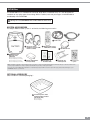
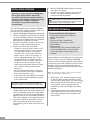
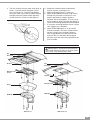
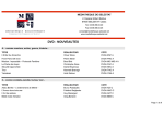
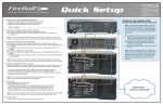
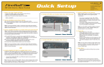
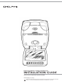
DELPHI MOBILE VIDEO DVDM-800
INSTALLATION GUIDE
Professional Installation Recommended
Caution: Fragile, do not drop!
Important: This manual contains important safety and operating information. Please read and follow the instructions in this manual.
Failure to do so could result in personal injury, death, and/or damage to your DVDM-800 and/or to your vehicle.
CAUTION
• Use only a soft, dry cloth to clean the outside of your DVDM-800 and any peripherals.
• Do not use any solvents, chemicals, or
cleaning solutions containing alcohol,
ammonia, or abrasives.
• Do not use sprays near your unit.
• Refrain from using food or drinks near the
remote control. Spilling food or drinks on
the remote could damage it.
• Keep hands or materials away from the LCD
video monitor to avoid surface scratches.
• Push the panel buttons gently to avoid
damage to the hinge.
• Close the unit when not in use.
• Do not leave the unit’s dome light on while
the vehicle is unattended. The dome light
could drain the vehicle’s battery.
• When not in use, place the remote control
and headphones where they will not be
damaged.
• Before putting on headphones, always
adjust the volume setting at the lowest
level to avoid possible hearing damage.
IMPORTANT
An LCD panel and/or video monitor may be
installed in a vehicle and visible to the driver
if the LCD panel or video monitor is used for
vehicle information, system control, rear or
side observation, or navigation. If the LCD
panel or video monitor is used for television
reception, video, or DVD play, the LCD panel
or video monitor must be installed so that
these features will only function when the
vehicle is in “park” or when the vehicle’s
parking brake is applied.
An LCD panel or video monitor used for
television reception, video, or DVD play that
operates when the vehicle is in gear or
when the parking brake is not applied
must be placed where it will not be visible,
directly or indirectly, to the operator of the
motor vehicle.
Caution: Fragile, do not drop!
2
This is the safety alert symbol. It is used to alert you to
potential personal injury hazards. Obey all safety messages
that follow this symbol to avoid possible injury or death.
Warning: When using your DVDM-800, it is your sole
responsibility to secure and use the device in a manner
that will not cause accidents, personal injury or property
damage, or in any manner obstruct your view or interfere
with the operation of vehicle safety equipment.
It is your sole responsibility that this device is properly
installed and that these operating instructions are read
carefully, understood, and used consistent with the laws
of operation for any state or country in which you use
the device and with common sense. Failure to do so may
result in an accident and personal injury, death, and/or
property damage to your DVDM-800 and/or to your vehicle.
DELPHI DISCLAIMS ALL LIABILITY FOR ANY USE OF THIS
PRODUCT IN A WAY THAT MAY CAUSE ACCIDENTS,
DAMAGE, OR THAT MAY VIOLATE THE LAW.
Warning: To reduce the risk of fire or shock hazard,
do not expose DVDM-800 to rain or moisture.
Warning: This product utilizes a laser. Use of controls
or adjustments or performance of procedures other than
those specified herein may result in hazardous radiation
exposure. Do not open cover. Refer servicing to qualified
service technician.
CONTENTS
DVDM-800 . . . . . . . . . . . . . . . . . . . . . . . . . . . . . 3
Installation Overview . . . . . . . . . . . . . . . . . . . . 4
Mounting DVDM-800 . . . . . . . . . . . . . . . . . . . . . 4
Electrical Connections . . . . . . . . . . . . . . . . . . . . 6
Connecting the Dome Lights . . . . . . . . . . . . . . .7
System Test . . . . . . . . . . . . . . . . . . . . . . . . . . . . 7
Troubleshooting . . . . . . . . . . . . . . . . . . . . . . . . . 7
DVDM-800
The DVDM-800 unit is intended for overhead, drop-down installation only. It is not designed for
seat-back or any other type of mounting. When installed, rear-seat passengers should be able to
comfortably view DVDM-800.
Warning: Do not install DVDM-800 where it will be within the driver’s view.
SYSTEM ACCESSORIES
The Delphi Mobile Video system is sold with the following accessories:
4
2
1
3
Two sets of wireless
headphones (requires 2 AAA
batteries, included)
Power cable
Remote control (requires
2 AAA batteries, included)
6
5
A/V cable
A/V connection box
DVDM-800 unit with
DVD player and 8"
LCD monitor
MV10002-11B1 (Gray, 1-year warranty)
MV10015-11B1 (Neutral, 1-year warranty)
MV10017-11B1 (Gray, 3-year warranty)
MV10016-11B1 (Neutral, 3-year warranty)
7
Wireless FM transmitter
(factory installed)
8
User Manual and
Installation Guide
9
Galvanized steel
mounting bracket
10
Screws and
spacers
Note: Installation materials sold separately include a shroud for a professional fit. Delphi highly recommends that you contact a professional to
ensure proper installation. To locate a professional installer in your area, contact your retailer.
It is your sole responsibility that installation is completed properly and will not result in personal injury, death, and/or damage to your
DVDM-800 and/or to your vehicle.
OPTIONAL ACCESSORY
(Not included in standard packaging.)
11
8" decorative plastic shroud
(mounting hardware included
with item 10 above)
MV10010-11B1 (Gray)
MV10014-11B1 (Neutral)
3
INSTALLATION OVERVIEW
Generally, it is best to install the DVDM-800
unit in place of the vehicle’s dome light.
For vehicles with factory-installed overhead
consoles in the headliner, consult the console
manufacturer for complete installation
instructions. Professional installation is
recommended.
The exact method for mounting the DVDM-800
unit will vary from vehicle to vehicle. Here is an
overview of the installation process:
1. Unpack DVDM-800 and identify all components.
2. Review and become familiar with the operating and installation literature. Note electrical
requirements and determine the installation
technique best suited to the vehicle.
3. Determine installation locations for all components, noting all potential obstacles.
4. Prepare the vehicle for installation:
• Locate an accessory power source (+12V
when the ignition key is in the ACC and
“on” positions; 0V when the ignition is
turned to “off”). Also locate a constant
power source (+12V DC at all times) as
well as a good grounding point. These
connection points are typically found at
the ignition switch, fuse box, radio, etc.
• To gain access to the vehicle’s wiring,
remove the ceiling panel and any interior
trim, using an upholstery hook tool if
necessary.
• Remove vehicle dome light, if necessary.
• Cut any required access holes (headliner,
other trim components, etc.).
• If shroud will be used, additional trimming
of the shroud may be required to conform
to the vehicle roof.
Caution: Take care when removing the dome light and
cutting the headliner to not damage the headliner fabric.
5. Route the power and A/V cables and any other
component/accessory wiring throughout the
vehicle, protecting wiring from sharp edges.
For guidance, refer to the wiring diagram on
page 6 as well as any instructions provided
with other hardware such as gaming systems.
6. Connect all electrical components, insert a
DVD, and verify that all system functions
work properly prior to final mounting in the
vehicle.
4
7. Mount DVDM-800, following the instructions
provided in this guide.
8. Recheck all system functions to ensure that
wiring is connected properly and that no
wires are kinked or pinched.
Warning: Failure to properly follow these instructions
could result in damage to the vehicle, its electronic system,
other property, or personal injury and/or death.
MOUNTING DVDM-800
Recommended Tools and Equipment
• Upholstery hook tool (for removal of
panels, if necessary)
• Scribe
• #1 and #2 Phillips screwdrivers
• Utility knife, razor knife, or shears
• Wire strippers
• Electrical tape
• Multimeter (to verify correct voltages and
continuity; Delphi does not recommend
using a test light or logic probe for this
purpose)
Depending on the roof geometry of the particular
vehicle in which you are installing DVDM-800,
there are three installation options: Attaching the
unit directly to the roof supports with the shroud,
bolting it into the mounting bracket alone, or
installing it with both the shroud and the mounting
bracket. See Figure 2.
Note: The following mounting sequence may be modified
based on the installation option chosen.
1. With panels, trim, and dome light removed,
install the video monitor temporarily to the
vehicle roof by opening the unit and inserting
bolts through the bolt holes directly into the
roof supports. Leave a gap between the
headliner and the outer flange of the video
monitor.
2. Following the contour of the roof, mark the
area to be trimmed on the shroud so that it
will fill the gap between the headliner and
outer flange.
3. Trim the shroud. Using a sharp utility knife or
shears, score the plastic along the cutline
with several passes, cutting a little deeper
each time. When you have cut about halfway
through the plastic, bend it back and forth
several times for a clean cut. See Figure 1.
Figure 1.
4. Remove the video monitor and hold the
shroud in place, checking the fit.
5. Make minor adjustments, if necessary.
6. Attach DVDM-800 and shroud using screws
through the perimeter screw bosses. Use
spacers provided to support shroud as
required. Do not overtighten. This can cause
the assembly to distort or bend. See Figure 2.
Use of screw locking compound recommended.
7. If using the mounting bracket, secure it to the
roof support cross-members.
8. Attach DVDM-800 (alone or as part of the
shroud assembly). The bolts should contact
the roof support cross-members directly
with no gap between the bolt and the roof
structure. Be sure that bolts do not pierce
the outer roof skin when fully fastened to the
cross-member.
Figure 2.
Warning: Failure to properly follow these instructions
could result in damage to the vehicle, its electronic system,
other property, or personal injury and/or death.
Roof
Roof support
Headliner
Roof
Roof support
Mounting bracket
(if used)
Headliner
Mounting bracket
Shroud
DVDM-800
DVDM-800
With Shroud
Without Shroud
5
Figure 3.
External Audio/Video
Input Device
External Audio/Video
Input Device
Power/Harness
R
AV In
V
FM
Transmitter
16 Pin Line
S-V
External
Audio/Video
Input Device
R
AV 2 In
L
L
Yellow/Battery
Black/Ground
RVDC/Acc
AV Out
V
R
L
External Audio/Video
Display Device
Video 1 In
Gnd
Video Out
Gnd
Audio L Out
Audio R Out
Audio 2 L In
Audio 2 R In
16
15
14
13
12
11
10
9
1
2
3
4
5
6
7
8
S Video In C
Gnd
Gnd
S Video in Y
Gnd
Gnd
Audio 1 L In
Audio 1 R In
1
3
2
POSITIVE/NEGATIVE SYSTEM
POSITIVE SYSTEM
1 Purple/Ground
2 Blue/12V
3 Green/Door Trigger
ELECTRICAL CONNECTIONS
1. Connect the power cable and A/V components
to the appropriate vehicle electrical connections
(Figure 3):
a. Insert the 16-pin mini-DIN connector into
the mini-DIN connector on the back of the
system.
b. Route A/V lead through vehicle, avoiding
sharp edges and rub points, to location of
A/V input/output box.
6
NEGATIVE SYSTEM
1 Purple/12V
2 Blue/Ground
3 Green/Door Trigger
2. Connect the supplied power cable to the vehicle
electrical system, tapping into an accessory
hot line, constant battery line, and ground.
3. Verify that all system functions operate
properly before final mounting. Refer to the
Delphi Mobile Video DVDM-800 User Manual
for detailed operating information.
Warning: Failure to properly follow these instructions
could result in damage to the vehicle, its electronic system,
other property, or personal injury and/or death.
CONNECTING THE DOME LIGHTS
The dome lights on DVDM-800 require three
connections to the vehicle wiring. First, determine
which of the two common types of dome light
circuits your vehicle has: positive or negative
switched. Positive switched systems turn the
interior lights on by supplying voltage to them.
Negative switched systems illuminate the bulbs
by applying ground. The wires at the dome light
will help you determine which system you have.
• On a positive switched system, with all vehicle
doors closed and lights out, both wires at the
dome light will rest at ground. When the light is
turned on, one of these wires will switch to
+12V DC (the vehicle’s switching wire).
Connect the purple/brown (lamp auto) wire to
the vehicle’s switched wire. Then, connect the
red/black (lamp on) wire to a fused constant
12V source and the black/red (lamp common)
wire to a good ground.
• On a negative switched system, with all vehicle
doors closed and lights out, both wires at the
dome light will rest at +12V DC. When the light
is turned on, one of these wires will switch to
ground (the vehicle’s switching wire).
Connect the purple/brown (lamp auto) wire to
the vehicle’s switched wire. Then, connect the
red/black (lamp on) wire to a good ground and
the black/red (lamp common) wire to a fused
constant 12V source.
Note: Some vehicles incorporate transistorized control of the
dome light circuit and may not support the additional current
draw of the video monitor lights. In these cases, it may be
necessary to connect the purple/brown (lamp auto) wire to
the door pin switch wire.
TROUBLESHOOTING
If the Delphi Mobile Video unit does not appear
to be functioning properly, please follow these
troubleshooting guidelines:
No power at the DVD system:
1. Verify 12V DC power at the power cable
behind the video monitor.
2. Verify the ground connection by conducting a
continuity test from a known good ground to
the black wire of the power cable.
Power on, no video or sound:
1. Verify selection of the correct A/V source
(A/V1, AUX, or built-in DVD): Source should
be “on” and playing a known good DVD.
2. Verify connections at both ends of the source
component harness.
Picture with no sound:
1. Push and hold the volume up button on the
remote control until sound is heard over
wireless headphones.
2. Make sure radio is tuned to the correct
frequency for the FM transmitter.
3. Verify all connections per the electrical
wiring diagram on page 6.
Remote control doesn’t work:
1. Check the strength of the two AAA batteries;
if they are weak, replace both batteries with
new ones.
Refer to the Delphi Mobile Video DVDM-800 User
Manual for additional troubleshooting information.
Warning: Failure to properly follow these instructions
could result in damage to the vehicle, its electronic system,
other property, or personal injury and/or death.
SYSTEM TEST
When installation is complete, test the following:
1. Power connection
2. Dome light function
3. IR remote control
4. IR headphone function
5. A/V input/output functions
6. Wireless FM transmitter functions
7
Delphi Corporation
1441 West Long Lake Road
Troy, Michigan 48098-5090
U.S.A.
Customer Service: [1] 877.GO DELPHI
www.delphi.com
©2004 Delphi Corporation. All rights reserved.
DPSS-04-E-027