1
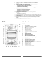
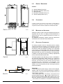
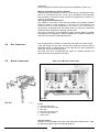
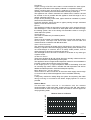
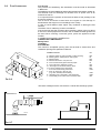
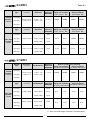
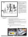
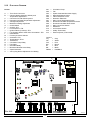
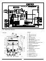
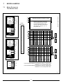
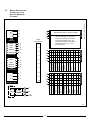
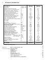
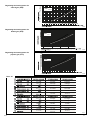
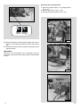
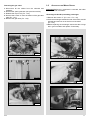
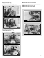
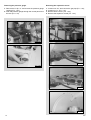
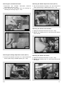
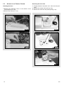
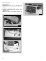
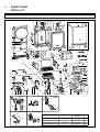
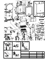
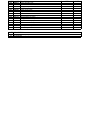
Installation
Instructions
Type C Boilers
G.C.N: 47-116-14
47-116-15
LEAVE THESE INSTRUCTIONS
WITH THE END-USER
Country of destination: GB
TABLE OF CONTENTS
1.
GENERAL INFORMATION
1.1 GENERAL INSTRUCTIONS
1.2 OVERALL VIEW
2.
INSTALLATION
2.1
2.2
2.3
2.4
2.5
2.6
2.7
2.8
2.9
2.10
2.11
2.12
REFERENCE STANDARDS
SITING THE APPLIANCE
OVERALL DIMENSIONS
CLEARANCES
MOUNTING THE APPLIANCE
ELECTRICAL CONNECTION
GAS CONNECTION
WATER CONNECTIONS
FLUE CONNECTION
ROOM THERMOSTAT CONNECTION
ELECTRICAL/SYSTEM DIAGRAMS
WATER CIRCUIT DIAGRAMS
3.
COMMISSIONING
3.1
3.2
3.3
3.4
3.5
3.6
3.7
3.8
3.9
INITIAL PREPARATION
CONTROL PANEL
REMOVING THE FRONT PANEL
INITIAL START UP
OPERATIONAL ADJUSTMENTS
COMBUSTION ANALYSIS
FUME DISCHARGE MONITORING
BOILER SAFETY SYSTEMS
DRAINING THE SYSTEM
4.
GAS ADJUSTMENTS
GAS ADJUSTMENT TABLE
4.1 CHANGING THE TYPE OF GAS
5.
MAINTENANCE
6.
MISCELLANEOUS
6.1 WIRING DIAGRAM FOR TWO HEATING ZONES
6.2 WIRING DIAGRAM FOR CONNECTION TO AN ARISTON UNVENTED CYLINDER
7.
TECHNICAL INFORMATION
2
1.
GENERAL
INFORMATION
This manual is an integral and essential part of the product. It should be kept
with the appliance so that it can be consulted by the user and our authorised
personnel.
Please carefully read the instructions
and notices about the unit contained in
this manual, as they provide important
infor mation regarding the safe
installation, use and maintenance of
the product.
For operating instructions please
consult the separate User’s Manual.
CO034A
1.1
GENERAL INSTRUCTIONS
Read the instructions and recommendations in these Installation Instructions
carefully to ensure proper installation, use and maintenance of the appliance.
Keep this manual in a safe place. You may need it for your own reference while
our Servicing Centre technicians or your installer may need to consult it in the
future.
This is a combined appliance for the production of central heating (C.H.) and
domestic hot water (D.H.W.).
This appliance must be used only for the purpose for which it is designed.
The manufacturer declines all liability for damage caused by improper or
negligent use.
No asbestos or other hazardous materials have been used in the fabrication of
this product.
Before connecting the appliance, check that the information shown on the data
plate and the table on pages 4-5 comply with the electric, water and gas mains
of the property. You will find the data plate on the reverse of the control panel.
The gas with which this appliance operates is also shown on the label at the
bottom of the boiler.
Do not install this appliance in a damp environment or close to equipment
which spray water or other liquids.
Do not place objects on the appliance.
Do not allow children or inexperienced persons to use the appliance without
supervision.
If you smell gas in the room, do not turn on light switches, use the telephone or
any other object which might cause sparks.
Open doors and windows immediately to ventilate the room.
Shut the gas mains tap (on the gas meter) or the valve of the gas cylinder and
call your Gas Supplier immediately.
If you are going away for a long period of time, remember to shut the mains gas
tap or the gas cylinder valve.
Always disconnect the appliance either by unplugging it from the mains or
turning off the mains switch before cleaning the appliance or carrying out
maintenance.
In the case of faults or failure, switch off the appliance and turn off the gas
tap. Do not tamper with the appliance.
For repairs, call your local Authorised Servicing Centre and request the use of
original spare parts. For in-guarantee repairs contact MTS (GB) Limited.
Check the following at least once a year:
1 - Check the seals for the water connections; replacement of any faulty seals.
2 - Check the gas seals; replacement of any faulty gas seals.
3 - Visual check of the entire unit.
4 - Visual check of the combustion process or analysis of combustion byproducts (see section 3.6) and cleaning of the burner if needed.
3
5 - If called for by point. 3, dismantling and cleaning of the combustion
chamber.
6 - If called for by point. 4, dismantling and cleaning of the burner jets.
7 - Visual check of the primary heat exchanger:
- check for overheating in the blade assembly;
- clean the exhaust fan if needed.
8 - Adjustment of the flow rate of the gas: flow rate for lighting, partial load and
full load.
9 - Check of the heating safety systems:
- safety device for maximum temperature;
- safety device for maximum pressure.
10- Check of the gas safety systems:
- safety device for lack of gas or flame ionisation (detection
electrode);
- safety device for gas cock.
11- Check of the electrical connection (make sure it complies with the instructions
in the manual).
12- Check of domestic hot water production efficiency (flow rate and temperature)
13- General check of the combustion by-products of the discharge/ventilation
system.
14- Check of the general performance of the unit.
FIG. 1.0
1.2
OVERALL VIEW
LEGEND:
1.
2.
3.
4.
5.
6.
7.
8.
9.
10.
11.
12.
13.
14.
15.
16.
17.
18.
19.
20.
21.
22.
23.
24.
25.
IN013A
4
Flue connector
Air intake for twin pipe flue systems
Fan
Combustion chamber hood
Main heat exchanger
Safety thermostat
Combustion chamber
Combustion chamber insulation panel
Burner
Detection electrode
Ignition electrodes
Motorised diverter valve
Main circuit temperature probe
Main circuit flow switch
Domestic hot water temperature probe
Gas valve
Spark generator
Domestic hot water flow switch
Domestic cold water inlet filter
Secondary heat exchanger
Circulation pump with automatic air release valve
Safety valve (3 bar)
Expansion vessel
Air pressure switch
Combustion analysis intakes
2.
INSTALLATION
The technical information and instructions provided herein below are
intended for the installer so that the unit may be installed correctly and
safely.
2.1
REFERENCE STANDARDS
The installation and initial start up of the boiler must be by a CORGI
Approved Installer in compliance with the installation standards currently in
effect, as well as with any and all local health and safety standards i.e..
CORGI .
This appliance must be installed by a competent installer in
accordance with current Gas Safety (installation & use)
Regulations.
The installation of this appliance must be in accordance with the relevant
requirements of the current Gas Safety (installation & use) Regulations, the
Local Building Regulations, the current I.E.E. Wiring Regulations, the
byelaws of the local water authority, and in Scotland, in accordance with the
Building Standards (Scotland) Regulation and Health and Safety document
No. 635 “Electricity at work regs. 1989”.
Installation should also comply with the following British Standard Codes of
Practice:
Low pressure
pipes
BS 6891
1988
Boilers of rated input
not exceeding 60 kW
BS 6798
1987
Forced circulation hot
water system
BS 5449
1990
Flues
BS 5546
BS 5440-1
1990
1990
Air supply
BS 5440-2
1989
Installation of gas hot water
supplies for domestic purposes
( 2nd family gases)
2.2
SITING THE APPLIANCE
The appliance may be installed in any room or indoor area, although
particular attention is drawn to the requirements of the current I.E.E. Wiring
Regulations, and in Scotland, the electrical provisions of the Building
Regulations applicable in Scotland, with respect to the installation of the
combined appliance in a room containing a bath or shower.
Where a room-sealed appliance is installed in a room containing a bath
or shower the boiler and any electrical switch or appliance control,
utilising mains electricity should be situated so that it cannot be
touched by a person using the bath or shower.
The location must permit adequate space for servicing and air circulation
around the appliance as indicated in paragraph 2.4.
The location must permit the provision of an adequate flue and termination.
For unusual locations special procedures may be necessary.
BS 6798-1987 gives detailed guidance on this aspect.
A compartment used to enclose the appliance must be designed specifically
for this purpose. No specific ventilation requirements are needed for the
installation within a cupboard.
This appliance is not suitable for outdoor installation.
The type C appliances (in which the combustion circuit, air vent intake
and combustion chamber are air-tight with respect to the room in
which the appliance is installed) can be installed in any type of room.
There are no limitations with respect to ventilation and the volume of the
room itself. The boiler must be installed on a solid, permanent wall to prevent
access to the electrical parts (when live) through the aperture on the back
frame.
5
2.3
OVERALL DIMENSIONS
LEGEND:
A = Central Heating Flow (3/4”)
B = Domestic Hot Water Outlet (1/2”)
C = Gas Inlet (3/4”)
D = Domestic Cold Water Inlet (1/2”)
E = Central Heating Return (3/4”)
2.4
CLEARANCES
In order to allow for access to the interior of the boiler for
maintenance pur poses, the boiler must be installed in
compliance with the minimum clearances indicated in FIG. 2.2
FIG. 2.1
QT002A
2.5
MOUNTING THE APPLIANCE
Fasten the boiler in place using the template and anchors
supplied with the unit. It is highly recommended that a
spirit level be used to position the boiler so that it is
perfectly level.
For additional information, please consult the instructions
contained in the connection kit and the flue kit.
2.7
ELECTRICAL CONNECTION
For safety purposes, have a competent person carefully
check the electrical system in the proper ty, as the
manufacturer will not be held liable for damage caused by
the failure to earth the appliance properly or by anomalies
in the supply of power. Make sure that the residential
electrical system is adequate for the maximum power
absorbed by the unit, which is indicated on the rating plate.
In addition, check that the section of cabling is appropriate
for the power absorbed by the boiler.
FIG. 2.2
The boiler operates with alternating current, as indicated in
the technical information table section in 6, where the
maximum absorbed power is also indicated. Make sure
that the connections for the neutral and live wires
correspond to the indications in the diagram. The
appliance electrical connections are situated on the
reverse of the control panel (see the servicing manual for
further information)
DM004A
IMPORTANT!
FIG. 2.3
In the event that the power supply cord must be changed,
replace it with one with the same specifications. Make the
connections to the terminal board located within the
control panel, as follows:
- The yellow-green wire should be connected to the
” symbol; make sure to reterminal marked with the “
use the ferrule mounted on the other supply cord;- The
blue wire should be connected to the terminal marked “N”;
- The brown wire should be connected to the terminal
VR001A
6
marked “L”.
Note: The diagrams for the electrical system are indicated in section 2.11.
Warning, this appliance must be earthed.
External wiring to the appliance must be carried out by a qualified technician
and be in accordance with the current I.E.E. Regulations and applicable
local regulations. The Genus range of boilers are supplied for connection to
a 230 V~ 50 Hz supply.
The supply must be fused at 3 A.
The method of connection to the electricity supply must facilitate complete
electrical isolation of the appliance, by the use of a fused double pole
isolator having a contact separation of at least 3 mm in all poles or
alternatively, by means of a 3 A fused three pin plug and unswitched
shuttered socket outlet both complying with BS 1363.
The point of connection to the Electricity supply must be readily accessible
and adjacent to the appliance unless the appliance is installed in a bathroom
when this must be sited outside the bathroom.
2.8
GAS CONNECTION
2.9
WATER CONNECTIONS
The local gas region contractor connects the gas meter to the service pipe.
If the gas supply for the boiler serves other appliances ensure that an
adequate supply is available both to the boiler and the other appliances
when they are in use at the same time.
Pipe work must be of an adequate size. Pipes of a smaller size than the
boiler inlet connection should not be used.
VIEW OF THE BOILER CONNECTIONS
FIG. 2.4
FIG. 2.5
KT002A
SC008A
LEGEND:
A
B
C
D
E
F
= Central Heating Flow
= Domestic Hot Water Outlet
= Gas Inlet
= Domestic Cold Water Inlet
= Central Heating Return
= Safety Valve
CENTRAL HEATING
Detailed recommendations are given in BS 6798:1987 and BS 5449-1:1990,
the following notes are given for general guidance.
7
PIPE WORK:
Copper tubing to BS EN 1057:1996 is recommended for water pipes.
Jointing should be either with capillary soldered or compression fittings.
Where possible pipes should have a gradient to ensure air is carried
naturally to air release points and water flows naturally to drain taps.
The appliance has a built-in automatic air release valve, however it should
be ensured as far as possible that the appliance heat exchanger is not a
natural collecting point for air.
Except where providing useful heat, pipes should be insulated to prevent
heat loss and avoid freezing.
Particular attention should be paid to pipes passing through ventilated
spaces in roofs and under floors.
BY-PASS:
The appliance includes an automatic by-pass valve, which protects the main
heat exchanger in case of reduced or interrupted water circulation through
the heating system, due to the closing of thermostatic valves or cock-type
valves within the system.
SYSTEM DESIGN:
This boiler is suitable only for sealed systems.
Drain Cocks:
These must be located in accessible positions to permit the draining of the
whole system. The taps must be at least 15mm nominal size and
manufactured in accordance with BS 2870:1980.
SAFETY VALVE DISCHARGE:
The discharge should terminate facing downward on the exterior of the
building in a position where discharging (possibly boiling water & steam) will
not create danger or nuisance, but in an easily visible position, and not
cause damage to electrical components and wiring.
The discharge must not be over an entrance or a window or any other type
of public access.
AIR RELEASE POINTS:
These must be fitted at all high points where air naturally collects and must
be sited to facilitate complete filling of the system.
The appliance has an integral sealed expansion vessel to accommodate the
increase of water value when the system is heated.
It can accept up to 6 l (1.3 gal) of expansion water. If the heating circuit has
an unusually high water content, calculate the total expansion and add an
additional sealed expansion vessel with adequate capacity.
MAINS WATER FEED - CENTRAL HEATING:
There must be no direct connection to the mains water supply even through
a non-return valve, without the approval of the Local Water Authority.
FILLING:
A temporary method for initially filling the system and replacing lost water
during servicing in accordance with Water Supply Byelaw 14 must be
provided.
DOMESTIC WATER
The domestic water must be in accordance with the relevant
recommendation of BS 5546:1990. Copper tubing to BS EN 1057:1996 is
recommended for water carrying pipe work and must be used for pipe work
carrying drinking water.
RESIDUAL HEAD OF THE BOILER
VR003A
8
2.9
FLUE SYSTEM
The provision for satisfactory flue termination must be made as described
in BS 5440-1.
The appliance must be installed so that the flue terminal is exposed to outdoor air.
The terminal must not discharge into another room or space such as an
outhouse or lean-to.
It is important that the position of the terminal allows a free passage of air
across it at all times.
The terminal should be located with due regard for the damage or
discolouration that might occur on buildings in the vicinity.
In cold or humid weather water vapour may condense on leaving the flue
terminal.
The effect of such “steaming” must be considered.
If the terminal is less than 2 metres above a balcony, above ground or above
a flat roof to which people have access, then a suitable terminal guard must
be fitted. When ordering a terminal guard, quote the appliance model
number.
A suitable terminal guard is available from:
TOWER FLUE COMPONENTS
Morley Road
Tonbridge
Kent TN9 1RA
The minimum acceptable spacing from the terminal to obstructions and
ventilation openings are specified in FIG. 2.6.
FLUE CONNECTIONS
BC
F
G
F D
HI
J
A
E
L
K
G
FIG. 2.6
TERMINAL POSTION
mm
A - Directly below an open window or other opening
B - Below gutters, solid pipes or drain pipes
C - Below eaves
D - Below balconies or car-port roof
E - From vertical drain pipes and soil pipes
F - From internal or external corners
G - Above ground or below balcony level
H - From a surface facing a terminal
I - From a terminal facing a terminal
J - From an opening in the car port
(e.g. door, window) into dwelling
K - Vertically from a terminal in the same wall
L - Horizontally from a terminal in the same wall
300
75
200
200
75
300
300
600
1200
1200
1500
300
FU010A
The boiler is designed to be connected to a coaxial flue discharge system.
Ø 60/100 mm
FU025A
FU002A
FIG. 2.7
9
In addition, it is also possible to use a split (twin pipe)
system by fitting a special adaptor to the flue connector
and using the aperture for the air vent intake located on
the top part of the combustion chamber.
To utilise the air intake it is necessary to:
1. Remove the bottom of the air intake by cutting it with a
suitable knife (see FIG. 2.8);
2. Insert the elbow into the air intake until it reaches the
lower end. (There is no need to use gaskets or sealing
componds).
The components marked * in FIG 2.9 are present or absent
depending on the type of flue system used by the installer.
FIG. 2.8
FU05A
Ø 80 mm
FIG. 2.9
FU004A
FU006A
IMPORTANT!
COAXIAL SYSTEMS
For all flue systems, a restrictor
must always be inserted into the
boiler’s flue connector; the
restrictor must be ø 43 or ø 41 in
diameter depending on the length
of piping indicated in Table 2.1.
The diagrams illustrate some of the
various designs for coaxial or twin
pipe flue systems.
For fur ther infor mation on
discharge/ventilation accessories,
see the F L U E P I P E A C C E S S O R I E S
MANUAL.
FIG. 2.10
FU001A
10
TABLE 2.1
23 MFFI
Exhaust
Type
Coaxial
Systems
ø 60/100
Restrictor
ø 43 mm
NO
Restrictor
Maximum
Extension
Exhaust/Air
L min = 0.5 m
L max = 2 m
L min = 2 m
L max = 4 m
L=4m
Restrictor
ø 43 mm
NO
Restrictor
Maximum
Extension
Exhaust/Air
Risk of Condensation Forming
Piping insulated
Piping not insulated
ø 43 restrictor NO
ø 43 restrictor NO
C12 (xx)
C32 (xx)
NONE
NONE
NONE
NONE
C42 (xx)
Exhaust
Type
43 m
C12 (xy)
C32 (xy)
Twin Pipe
Systems
ø 80/80
L max = 11.5 m
C42 (xy)
C52 (xy)
Risk of Condensation Forming
Piping insulated
Piping not insulated
ø 43 restrictor NO
ø 43 restrictor NO
L max = 11,4 m
L min = 11.5 m
43 m
L max = 43 m
43 m
L min = 11,4 m
40 m
4.3 m
6.9 m
4.3 m
6.9 m
NONE
5,7 m
NONE
21,7 m
L max = 40m
C82 (xy)
27 MFFI
Exhaust
Type
Coaxial
Systems
ø 60/100
Restrictor
ø 41 mm
NO Restrictor
L min = 0.5 m
L max = 1 m
L min = 1 m
L max = 4 m
Restrictor
ø 41 mm
NO Restrictor
Maximum
Risk of Condensation Forming
Extension Piping not insulated
Piping insulated
Exhaust/Air ø 41 restrictor NO restrictor ø 41 restrictor NO restrictor
C12 (xx)
C32 (xx)
L=4m
NONE
NONE
NONE
NONE
C42 (xx)
Exhaust
Type
Maximum
Risk of Condensation Forming
Extension Piping not insulated
Piping insulated
Exhaust/Air ø 41 restrictor NO restrictor ø 41 restrictor NO restrictor
62 m
C12 (xy)
C32 (xy)
Twin Pipe
Systems
ø 80/80
L max = 38 m
C42 (xy)
C52 (xy)
C82 (xy)
L max = 34 m
L min = 38 m
62 m
L max = 62 m
62 m
L min = 34 m
54 m
8m
11 m
19 m
31 m
8m
11 m
19 m
31 m
L max = 54 m
L = Sum of the total length of exhaust + air intake piping.
11
In calculating the lengths of the pipes, the
maximum length “L” must also take into
consideration the values for the
exhaust/air intake end terminals, as well
as 90° elbows for coaxial systems.
The C52 types must comply with the
following requirements:
1 - The exhaust/ air intake pipes must
have the same diameter of ø 80 mm.
2 - If elbows are to be inserted into the
air intake and/or exhaust system, the
calculation of the overall length must
take into consideration the values for
each elbow, see the F L U E P I P E
ACCESSORIES MANUAL.
3 - The exhaust pipe must protrude by at
least 0.5 m above the top of the roof
in the event that it is located on the
opposite side to the side with the air
intake (this condition is not obligatory
when the air intake and exhaust are
located on the same side of the
building).
TWIN PIPE
SYSTEMS
FIG. 2.11
2.10 ROOM THERMOSTAT
CONNECTION
FU007A
To connect a room thermostat, it is necessary to:
1. - Open the control panel as indicated in section 3.3.
2.- Remove the link “A” from the terminal block on the reverse of the control panel.
3. - Insert the thermostat cable through the cable grommet and fasten it by means of the
cable-clamp provided.
4. - Then connect the thermostat wires to the terminal block.
5.- If a remote time clock is to be fitted, disconnect the integral time clock from the P.C.B.
6. - Using a volt-free switching time clock, connect the switching wires from the time clock
following points 1-4 above.
7. - If using an external time clock and room thermostat, these must be connected in
series as points 1-7 above.
Note:
Only a two-wire type room thermostat can be used.
An anti-frost device is built-in to the appliance’s electronic regulation
system.
A
Fo016A
12
Fo017A
ELECTRICAL DIAGRAM
A01
A02
A03
A04
A05
A06
A07
A08
A09
A10
A11
A12
A13
A14
LEGEND:
Colours:
Gry
=
Wh
=
Pnk
=
Brn
=
Bl
=
Blk
=
Rd/Blk =
Grey
White
Pink
Brown
Blue
Black
Red/Black
K
FIG. 2.12
Blk
Blk
Blk
Gry
Gry
Pnk
Pnk
J
Circulation Pump
Fan
Spark Generator/Gas Valve Supply
Motorised Diverter Valve
Flame Detection Circuit
Detection Electrode
Main Circuit Temperature Probe
Domestic Hot Water Temperature Probe
Domestic Hot Water Flow Switch
Main Circuit Flow Switch
Modulator
Air Pressure Switch
Safety Thermostat
External (Room) Thermostat
Rd/Blk
Brn
Brn
Brn
Wh
Wh
=
=
=
=
=
=
=
=
=
=
=
=
=
=
=
=
=
=
=
=
Brn
Wh
Rd/Blk
C
D
E
F
G
H
I
J
K
L
M
N
O
P
Q
R
S
T
V
U
Time Clock Connector
Central Heating Selection (Winter) and
Temperature Adjustment
Connector for Total Check System
Domestic Hot Water Temperature Adjustment
Soft-light Adjustment
Maximum Heating Adjustment
On/Off Switch
On/Off L.E.D.
Fume Sensor L.E.D.
Ignition Failure (Lockout) L.E.D.
Low System Water Level/Lack of Circulation L.E.D.
Reset Button
Economy/Comfort Selector
Overheat L.E.D.
Temperature L.E.D.s
Transformer
Circulation Pump Relay
Fan Relay
Gas Valve Relay
Motorised Diverter Valve Relay
Spark Generator
Anti-cycling Device Adjustment for Heating
Wh
Wh
Blk
Blk
=
=
Blk
Blk
Gry
Gry
Rd/Blk
Wh
Pnk
A
B
=
=
=
=
=
=
=
=
=
=
=
=
=
=
Wh
2.12
SE017A
13
FIG. 2.13
N
O
R
T
Q
S
K
J
U
L
M
SF014A
2.13
WATER CIRCUIT DIAGRAM
LEGEND:
FIG. 2.14
1.
2.
3.
4.
5.
6.
7.
8.
9.
10.
11.
12.
13.
14.
15.
16.
17.
18.
Fan
Main Heat Exchanger
Overheat Thermostat
Burner
Ignition Electrodes
Detection Electrode
Motorised Valve
Main Circuit Temperature Probe
Main Circuit Flow Switch
Automatic By-pass
Domestic Hot Water Temperature Probe
Secondary Heat Exchanger
Gas Valve
Domestic Hot Water Flow Switch
Domestic Water Inlet Filter
Pressure Gauge
Safety Valve
Circulation Pump with Automatic
Air Release Valve
19. Expansion Vessel
20. Air Pressure Switch
SI017A
14
A.
B.
C.
D.
E.
Central Heating Flow
Domestic Hot Water Outlet
Inlet Gas
Domestic Cold Water Inlet
Central Heating Return
3.
COMMISSIONING
3.1
INITIAL PREPARATION
MTS (GB) Limited support the
initiative. Within the information pack
you will find a copy of the
logbook. It is important that this is
completed in the presence of your customer, they are shown how to us it,
and it is signed by them. Please instruct your customer that they must have
their
logbook with them whenever they contact a service engineer
or us.
Preliminary electrical system checks to ensure electrical safety must be
carried out by a competent person i.e. polarity, earth continuity, resistance to
earth and short circuit.
FILLING THE HEATING SYSTEM:
Remove the panels of the case and lower the control panel (see section
3.3 for further information).
Open the central heating flow and return cocks supplied with the
connection kit.
Unscrew the cap on the automatic air release valve one full turn and leave
open permanently.
Close all air release valves on the central heating system.
Gradually open valve(s) at the filling point (filling-loop) connection to the
central heating system until water is heard to flow, do not open fully.
Open each air release tap starting with the lower point and close it only
when clear water, free of air, is visible.
Purge the air from the pump by unscrewing anticlockwise the pump
plug and also manually rotate the pump shaft in the direction
indicated by the pump label to ensure the pump is free.
Close the pump plug.
Continue filling the system until at least 1 bar registers on the pressure
gauge.
Inspect the system for water soundness and remedy any leaks
discovered.
FILLING OF THE D.H.W. SYSTEM:
Close all hot water draw-off taps.
Open the cold water inlet cock supplied with the connection kit.
Open slowly each draw-off tap and close it only when clear water, free of
bubbles, is visible
GAS SUPPLY:
Inspect the entire installation including the gas meter, test for soundness
and purge, all as described in BS 6891:1988.
Open the gas cock (supplied with the connection kit) to the appliance and
check the gas connector on the appliance for leaks.
When the installation and filling are completed turn on the central heating
system (section 3.4) and run it until the temperature has reached the boiler
operating temperature. The system must then be immediately flushed
through.
The flushing procedure must be in line with BS 7593:1992 code of practice
for treatment of water in domestic hot water central heating systems.
During this operation, we highly recommend the use of a central heating
flushing detergent (Fernox Superfloc or equivalent), whose function is to
dissolve any foreign matter that may be in the system.
Substances different from these could create serious problems to the
pump or other components.
The use of an inhibitor in the system such as Fernox MB-1 or equivalent is
strongly recommended to prevent corrosion (sludge) damaging the boiler
and system.
Failure to carry out this procedure may invalidate the appliance
warranty.
15
3.2
CONTROL PANEL
LEGEND:
3.3
FR025A
A - On/Off knob
B - Domestic hot water temperature adjustment knob
C - Central heating selection (winter) and temperature
adjustment knob
D - On/Off L.E.D. (green)
E - Fume sensor L.E.D. (yellow)
F - Ignition failure (lockout) L.E.D. (red)
G - “Economy/Comfort” mode selection knob
H - Ignition failure (lockout) and/or overheat reset button
I - Overheat L.E.D. (red)
J - Low system water level L.E.D. (red)
K - Central heating temperature L.E.D (yellow)
L - Time clock
M - Heating system pressure gauge
FIG. 3.1
In order to access the inside of the boiler, it is necessary to unscrew
the fastening screws “A” of the control panel located on the lower part
of the panel itself.
The control panel moves downward and when pulled forward rotates
on two lateral hinges.
The panel stays in a semi-horizontal position, which allows access to
the inner parts of the boiler.
In order to increase the maneuvering space, it is possible to raise the
control panel and rotate it to a fully horizontal position.
REMOVING THE
FRONT PANEL
1
A
4
FO006A
2
B
FO009A
To dismantle the front
casing panel it is necessary
to:
1 - Remove the two screws
“B”;
2 - Lift the front casing panel
up and forward.
5
FO012A
3
FO008A
FO013A
16
3.4. INITIAL START-UP
THE CHECKS TO BE RUN BEFORE INITIAL START-UP ARE AS FOLLOWS:
1. Make sure that:
- the screw on the automatic air valve has been loosened when the
system is full;
- If the water pressure in the system is below 1 bar, bring it up to the
appropriate level;
- Check to see whether the gas cock is closed;
- Make sure that the electrical connection has been made properly and
that the earth wire is connected to an efficient earthing system;
- Supply power to the boiler by turning the On/Off switch “A” (see FIG.3.1)
- the L.E.D. “D” will illuminate - turn the selector knob “C” to the winter
/central heating position. This will start the circulation pump. After 7
seconds, the boiler will signal a shutdown due to ignition failure. Leave
the boiler as it is until all of the air has been bled from the lines.
- Loosen the cap on the head of the pump to eliminate any air pockets;
- Repeat the procedure for bleeding the radiators of air;
- Open the taps for a brief period;
- Check the system pressure and, if it has dropped, open the filling loop
again to bring the pressure back up to 1 bar.
2. Check the exhaust flue for the fumes produced by combustion.
3. Make sure that all gate valves are open;
4. Turn on the gas cock and check the seals on the connections, including
the one for the burner, making sure that the meter does not signal the
passage of gas. Check the connections with a soap solution and
eliminate any leaks.
5. Press the reset button “A” for the lighting system; the spark will light the
main burner. If the burner does not light the first time, repeat the
procedure.
6. Check the minimum and maximum pressure values for the gas going to
the burner; adjust it if needed using the values indicated in the table in
section 4 (See the relative section for burner pressure adjustment within
the servicing manual).
3.5
(See section 3.2 for references) it is possible to:
- Set the temperature of the heating system by adjusting the knob “C”
- Set the temperature of the domestic hot water by turning knob “B”
- The selector knob “G” allows the user to choose the economy mode
(position “E”) or the comfort mode (position “C”).
The economy mode is the normal state for the operation of the boiler,
since the domestic water is heated up only when a tap is turned on.
The comfort mode is a special operating state, because the water
contained in the secondary exchanger and in the primary exchanger is
kept in a preheated condition, thereby allowing a quicker delivery of
domestic water when required. The latter is therefore the more
convenient choice.
To access the areas in which adjustments are made, it is necessary to open
the control panel, as indicated in section 3.3, then remove the rear
inspection cover by unscrewing the two screws. Access is thereby provided
to the P.C.B. and to the following components:
1. the power supply cable connector;
2. the fuses;
3. the soft-light potentiometer the setting for which can range from the
minimum thermal power to the maximum;
4. the maximum thermal heating power potentiometer adjustable by the
minimum to maximum power (already calibrated in the factory to 70% of
the maximum thermal power);
5. the potentiometer for adjusting the ignition delay (anti-cycling) feature,
which can be set from 0 to 2 minutes (set in the factory at one minute);
6. the time clock connector.
OPERATIONAL
ADJUSTMENTS
17
3.6
The flue connector has two apertures, readings can be
COMBUSTION ANALYSIS
taken for the temperature of the combustion by-products
and of the combustion air, as well as of the concentrations
of O2 and CO2, etc. .
To access these intakes it is necessary to unscrew the front
screw and remove the metal plate with sealing gasket.
The best test conditions, with the maximum heating power,
are achieved by turning the selector knob “C” to the “max”
position and removing the electrical connection to the heating
sensor (see section 6.).
FU008A
3.7
FUME DISCHARGE
MONITORING
In the boiler, it is possible to monitor the correct operation of
the flue exhaust/air intake, checking for a loss of general
pressure in the system. Through the use of a differential
manometer connected to the test points of the combustion
chamber, it is possible to detect the ∆P of operation of the air
pressure switch.
The value detected should not be less than 0,55 mbar for
23kW and 0.75 mbar for 27kW under conditions of maximum
thermal power in order for the boiler to function properly and
without interruption.
FU009A
3.8
BOILER SAFETY SYSTEMS
The boiler is fitted with the following devices (see section 3.2 for references).
1 - IGNITION FAILURE:
This control signals an ignition failure on the burner 7 seconds after a
lighting failure. The L.E.D. “F” will illuminate to signal the shutdown
status.
The system can be reset by pressing and releasing the button “H” after
checking to make sure that the gas cock is open.
2 - CIRCULATION FAILURE:
This control signals that the safety pressure switch on the primary
circuit has not sensed a pressure of at least 1 bar within 40 seconds of
the activation of the circulation pump; the circulation pump comes to a
halt and the red L.E.D. “J” illuminates.
The system may be reset, after re-establishing the correct level of
pressure in the boiler, turning the “A” knob.
3 - OVERHEATING:
This control shuts off the boiler in the case where the primary circuit
reaches a temperature in excess of 105°C.
The red L.E.D.s “I” and “F” will illuminate to signal this shutdown
status.
The system can be reset by waiting a few minutes for the primary
exchanger to cool down and then by pressing and releasing the “H”
button.
4. LIMESCALE BUILD-UP:
The boiler is equipped with a device that limits the formation of
Limescale in the secondary exchanger by controlling the temperature of
the domestic hot water (max 61°C) and also controlling the temperature
of the water in the primary heating circuit.
18
5. ANTI-FROST DEVICE:
The boiler is equipped with a device that, in the event of the water
temperature going below 5°C, the 3-way diverter valve switches to
domestic hot water and the burner ignites at the minimum power until
the boiler water reaches a temperature of about 50°C.
This device operates only if the boiler is functioning perfectly and:
- the system pressure is sufficient;
- the boiler is powered electrically;
- the gas is distributed.
6 - EXHAUST DISCHARGE ANOMALY SHUTDOWN:
The boiler is fitted with safety devices, which in the event of defective
discharge of exhaust fumes, automatically interrupts the gas supply,
thereby shutting off the boiler.
The shutdown of the boiler is temporary and is indicated by the
illumination of the yellow L.E.D. “E” for a period of about 15 minutes.
Once this time period has passed and the discharge state of exhaust
fumes has returned to normal, the boiler automatically turns back on.
7 - SAFETY SHUTDOWN:
At the start of every lighting phase, the P.C.B. performs a series of
internal controls. If a malfunction occurs, the boiler will shutdown until
the problem has been resolved.
3.9
DRAINING THE SYSTEM
DRAINING THE HEATING SYSTEM
The heating system must be emptied as follows:
- Turn off the boiler;
- Open the drain valve for the system and place a container below to catch the
water that comes out;
- Empty the system at the lowest points (where present). If you plan on not
using the heating system for an extended period of time, it is recommended
that you add antifreeze with an ethylene glycol base to the water in the
heating lines and radiators if the ambient temperature drops below 0°C during
the winter.
This makes repeated draining of the entire system unnecessary.
DRAINING THE DOMESTIC HOT WATER SYSTEM
Whenever there is the danger of the temperature dropping below the freezing
point, the domestic hot water system must be drained as follows:
- Turn off the general water valve for the household plumbing system;
- Turn on all the hot and cold water taps;
- Empty the remaining water from the lowest points in the system (where
present).
19
4.
GAS ADJUSTMENTS
Methane Gas
G20
Liquid Butane Gas
G30
Liquid Propane Gas
G31
MJ/m3h
mbar
mbar
45.67
20
17
80.58
29
20
80.58
37
25
mm
mc/h
Kg/h
1.30
2.72
----
0.77
---2.02
0.77
---2.02
mbar
11.0 - 2.0
(*) - 6.0
(*) - 6.0
mc/h
Kg/h
1.30
3.15
----
0.77
---2.34
0.77
---2.31
mbar
11.0 - 1.6
(*) - 4.6
(*) - 6.0
CATEGORY II2H3+
Lower Wobbe Index (15°C;1013mbar)
Nominal Delivery Pressure
Minimum Delivery Pressure
23 MFFI
Main Burner: n. 13 jets (ø)
Consumption (15°C; 1013mbar)
Consumption (15°C; 1013mbar)
Gas Cock Outlet Pressure
max - min
27 MFFI
Main Burner: n. 15 jets (ø)
Consumption (15°C; 1013mbar)
Consumption (15°C; 1013mbar)
Gas Cock Outlet Pressure:
max - min
[1 mbar = 10,197 mmc.a.]
The outlet pressure of the gas cock is obtained by completely loosening the
screw on the solenoid. The maximum pressure of the gas to the burner will
be equal to the nominal delivery pressure minus the head loss within the
gas valve.
4.1
The boiler can be converted to use either methane (natural) gas (G20)
or LPG (G30 - G31) by an Authorised Service Centre.
The operations that must be performed are the following:
1. Replace the jets on the main burner (see table in section 4);
2. Adjust the maximum and minimum thermal capacity values for the boiler
(see table in section 4);
3. Replace the gas rating plate;
4. Adjust the maximum thermal power setting;
5. Adjust the soft-light feature;
6. Adjust the ignition delay feature for the heating system (can be set from 0
to 2 mins.).
CHANGING THE
TYPE OF GAS
CATEGORY II2H3+
Recommended Softlight Pressure
(mbar)
20
Methane
Gas
G20
Liquid
Butane
Gas
G30
Liquid
Propane
Gas
G31
8.0
16.0
16.0
5.
MAINTENANCE
It is recommended that the following inspections be carried out on the
boiler at least once a year:
1 - Check the seals for the water connections; replacement of any faulty
seals.
2 - Check the gas seals; replacement of any faulty gas seals.
3 - Visual check of the entire unit.
4 - Visual check of the combustion process or analysis of combustion byproducts (see section 3.6) and cleaning of the burner if needed.
5 - If called for by point. 3, dismantling and cleaning of the combustion
chamber.
6 - If called for by point. 4, dismantling and cleaning of the burner jets.
7 - Visual check of the primary heat exchanger:
- check for overheating in the blade assembly;
- clean the exhaust fan if needed.
8 - Adjustment of the flow rate of the gas: flow rate for lighting, partial load
and full load.
9 - Check of the heating safety systems:
- safety device for maximum temperature;
- safety device for maximum pressure.
10- Check of the gas safety systems:
- safety device for lack of gas or flame ionisation (detection
electrode);
- safety device for gas cock.
11- Check of the electrical connection (make sure it complies with the
instructions in the manual).
12- Check of domestic hot water production efficiency (flow rate and
temperature)
13- General check of the combustion by-products of the
discharge/ventilation system.
14- Check of the general performance of the unit.
21
240V
MAINS INPUT (3 AMP)
8
2
2
T6360B
ROOM
THERMOSTAT
ZONE 2
L
1
N
2
E
3
22
8
E
E
E
E
E
4
4
N
7
5
N
N
N
N
3
3
L
6
6
L
L
L
L
L
ZONE 2
4
Randall 3020 P
and 3060
E
E
HTG
ON
1
N
N
N
N
2
2
1
L
L
L
L
1
1
2
2
L
L
L
ZONE 1
PROGRAMMER
2
E
E
N
N
N
• 3
ZONE 1
3
Randall 922, 972
Link L-2-5
6
4
10
10
3
Towerchron MP
Link 1-4/6-11
ACL LS522, LS722
6
Towerchron FP
Link 1-5/4-7-9
4
3
HW
ON
6
Sunvic DHP 2201
1
1
Towerchron 2000
7
6
Sunvic ET 1451
Link 2-3-6
3
3
SWITCHMASTER 805, 900
Switchmaster 400, 600
4
N
E
L
1
Based on Honeywell controls
BOILER
Remove internal time clock plug
from the the P.C.B. then connect
room stat terminal block on the
reverse of the boiler control panel
(see section 2.10) to 9 + 10 on
the junction box.
PROGRAMMER
1
8
1
2
2
4
4
4
4
N
1
Switchmaster
Symphony, Sonata
L
2
BOILER ELECTRICAL SUPPLY CABLE
ZONE 2
Sangamo 410 Form 1
Link 3-6
1
3
Randall 102/102 E
Link 3-6
Randall 701, 702
Link L-6-5
1
Potterton EP2000/3000 Link L-5 EP2001/3001
4
3
Potterton Miniminder
Randall 4033
Link 1-6
3
3
Landis & Gyr RWB20
Microgyr
• 10
3
3
• 9
Landis & Gyr RWB2
Glowworm Mastermind
6
E
1
4
3
1
GREEN/YELLOW
• 7
Horstmann 425, 525, 527
Link L-2-5
10
L
ORANGE
L
9
N
GREY
• 6
N
2
4
BLUE
4
8
3
BROWN
3
• 5
Drayton Tempus 7
• 4
ST 6400/ST 6300 ST 6200
2
microGENUS 23-27 MFFI
2
N
5
E
• 1
5
3
TYPICAL
JUNCTION BOX
2
4
3
3
Pegler Sunvic
SP 50/100 (Link L-3)
V4043H
VALVE
10
GREEN/YELLOW
9
10
L
1
1
ORANGE
N
T6360B
ROOM
THERMOSTAT
2
9
3
GREY
3
ZONE1
4
2
6
5
BLUE
6
V4043H
VALVE
1
BROWN
2
WIRING DIAGRAM FOR
TWO HEATING ZONES
Sangamo M5
Link 1-6
3
7.1
4
MISCELLANEOUS
Honeywell ST 699B 1002
Link L-5-8
6
7.
• 2
• 8
If a room thermostat is not requied on Zone 1, insert a link
between 4 + 5 on the junction box.
If a room thermostat is not requied on Zone 2, insert a link
between 6 + 8 on the junction box.
SH010A
1
2
C/P
Cylinder
thermostat
Thermal
cut-out
1 C/P
2
Not
used
23
Sangamo 410 Form 1
Link 3-6
8
8
1
2
2
4
4
4
E
E
E
E
E
4
4
N
7
5
N
N
N
N
N
3
3
L
6
6
L
L
L
L
L
4
Randall 3020 P
and 3060
E
E
HTG
ON
E
E
N
N
N
N
2
2
1
1
N
N
N
• 3
L
L
L
L
1
1
2
2
L
L
L
L
PROGRAMMER
2
6
4
3
10
10
3
6
Towerchron MP
Link 1-4/6-11
Randall 922, 972
Link L-2-5
6
Towerchron FP
Link 1-5/4-7-9
3
ACL LS522, LS722
6
Sunvic DHP 2201
4
HW
ON
7
Sunvic ET 1451
Link 2-3-6
1
1
4
Towerchron 2000
3
3
SWITCHMASTER 805, 900
Switchmaster 400, 600
1
Switchmaster
Symphony, Sonata
N
microGENUS 23-27 MFFI
9
Remove internal time clock plug
from the the P.C.B. then connect
room stat terminal block on the
reverse of the boiler control panel
(see section 2.10) to 9 + 10 on
the junction box.
2
N
3
E
L
1
Based on Honeywell controls
BOILER
10
BOILER ELECTRICAL SUPPLY CABLE
PROGRAMMER
1
1
3
Randall 701, 702
Link L-6-5
Sangamo M5
Link 1-6
4
Randall 4033
Link 1-6
1
6
Randall 102/102 E
Link 3-6
P
3
8
Potterton EP2000/3000 Link L-5 EP2001/3001
1
3
• 10
Potterton Miniminder
240V
MAINS INPUT (3 AMP)
E
• 9
3
3
Landis & Gyr RWB20
Microgyr
E
4
2
3
N
Landis & Gyr RWB2
Glowworm Mastermind
1
4
L
• 7
1
3
Horstmann 425, 525, 527
Link L-2-5
V4043H
HOT WATER VALVE
L
GREEN/YELLOW
• 6
L
10
N
ORANGE
N
9
4
GREY
• 5
4
2
3
8
BLUE
3
• 4
Drayton Tempus 7
BROWN
E
3
ST 6400/ST 6300 ST 6200
V4043H
HEATING VALVE
5
10
2
ORANGE
GREEN/YELLOW
Pegler Sunvic
SP 50/100 (Link L-3)
9
L
GREY
N
2
• 1
3
TYPICAL
JUNCTION BOX
6
BLUE
1
5
2
T6360B
ROOM
THERMOSTAT
3
BROWN
4
2
6
2
1
5
2
3
3
4
4
1
Honeywell ST 699B 1002
Link L-5-8
6
7.2
WIRING DIAGRAM FOR
CONNECTION TO AN
ARISTON UNVENTED
CYLINDER
• 2
• 8
SH009A
TECHNICAL INFORMATION
Consumption at Nominal Capacity(G20)
max/min kW
max/min kW
%
%
%
%
%
Kg/h
mbar
m3/h
Gas Consumption after 10 Minutes*
(15°C, 1013 mbar) (G30-G31)
Temp. of exhaust fumes at nominal capacity
CO2 Content
m3
Kg/h
°C
%
O2 Content
%
CO Content
Minimum Ambient Temperature
Head Loss on Water Side (max) (∆T=20°C)
Residual Head of System
Heating Temperature
Domestic Hot Water Temperature
D.H.W. Flow Rate ∆T=35°C
D.H.W. Flow Rate ∆T=35°C
D.H.W. Minimum Flow Rate
Pressure of Domestic Hot Water
Expansion Vessel Capacity
Expansion Vessel Pre-load Pressure
Maximum Water Content of System
Maximum Heating Pressure
Nominal Pressure
Natural Gas (G20)
LPG (G30-G31)
Electrical Supply
Power Consumption
Protection Grade of Electrical System
Internal Fuse Rating
Weight
ppm
°C
mbar
bar
max/min °C
max/min °C
l/min
gal/min
l/min
max/min bar
l
bar
l
bar
mbar
mbar
V/Hz
W
IP
Kg
G.C. Number
*Calculated at 70% maximum output
Manufacturer:
Merloni TermoSanitari SpA - Italy
Commercial subsidiary: MTS (GB) LIMITED
MTS Building
Hughenden Avenue
High Wycombe
Bucks HP13 5FT
Telephone: (01494) 755600
Fax: (01494) 459775
internet: http://www.mtsgb.ltd.uk
E-mail: [email protected]
Technical Service Hot Line: (01494) 539579
27 MFFI
63AU4549
25.6/11.0
63AU4549
29.8/12.0
92.9
91.1
1.0
6.1
0.4
49.5
0.96
93.5
90.7
0.2
6.3
0.4
60
1.60
2.72
3.15
0.32/0.39
2.02/2.00
123
7.2
0.37
2.34/2.31
128.8
6.9
7.5
8.1
51.9
+5
200
0.25
82/42
56/36
9.7
2.2
2.6
8/0.2
6
1
130
3
20
30-37
230 / 50
140
X4D
FAST 2 AT
38
48
+5
200
0.25
82/42
56/36
11.4
2.6
2.6
8/0.2
6
1
130
3
20
30-37
230 / 50
155
X4D
FAST 2 AT
39
47-116-14
47-116-15
RECANATI
23 MFFI
CE Certification
Heat Input
Heat Output
Efficiency of Nominal Heat Input
Efficiency at 30% of Nominal Heat Input
Heat Loss to the Casing (∆T=50°C)
Flue Heat Loss with Burner Operating
Flue Heat Loss with Burner Off
Maximum Discharge of Fumes (G20)
Residual Discharge Head
23 99 84 1469 312 - Stampa: bieffe
7.
Servicing
Instructions
Type C Boilers
G.C.N: 47-116-14
47-116-15
LEAVE THESE INSTRUCTIONS
WITH THE END-USER
Country of destination: GB
TABLE OF CONTENTS
2
1.
SERVICING INSTRUCTIONS
1.1
REPLACEMENT
1.2
TO GAIN GENERAL ACCESS
- Removing the front panel
- Removing the sealed chamber frontal cover
- Removing the side panels
1.3
ACCESS TO THE COMBUSTION CHAMBER
- Removing the combustion cover
- Removing the burner and jets
- Removing the electrodes
- Removing the main heat exchanger
- Removing the air pressure switch
- Removing the fan
- Removing the venturi device
1.4
SERVICING AND REMOVAL OF THE GAS VALVE
- Setting the gas pressures
- Removing the spark generator
- Removing the gas valve
1.5
ACCESS TO THE WATER CIRCUIT
- Removing the D.H.W. (secondary) exchanger
- Removing the safety valve
- Removing the automatic air vent
- Removing the main circuit flow switch
- Removing the pump
- Removing the pressure gauge
- Removing the expansion vessel
- Removing the overheat thermostat
- Removing the heating temperature sensor (N.T.C.)
- Removing the D.H.W. temperature sensor (N.T.C.)
- Removing the divertor valve actuator
- Removing the D.H.W. flow switch
1.6
ACCESS TO THE CONTROL SYSTEM
- Checking the fuses
- Removing the time clock
- Removing the P.C.B.
2.
FAULT FINDING
2.1
FAULT FINDING GUIDE (FLOW-CHART)
3.
ELECTRICAL DIAGRAMS
4.
SHORT SPARE PARTS LIST
OF
PARTS
B063
1.
SERVICING INSTRUCTIONS
To ensure efficient safe operation, it is recommended that the
boiler is serviced annually by a competent person.
Before starting any servicing work, ensure both the gas and
electrical supplies to the boiler are isolated and the boiler is
cool.
Before and after servicing, a combustion analysis should be made
via the flue sampling point (please refer to the Installation Manual
for further details).
After servicing, preliminary electrical system checks must be
carried out to ensure electrical safety (i.e. polarity, earth continuity,
resistance to earth and short circuit).
1.1
REPLACEMENT
OF
2. The control panel moves downward and when pulled forward,
rotates on two lateral hinges; the panel stays in a semihorizontal position, which allows access to the inner parts of
the boiler (FIG. 1.2);
3. In order to increase the manouvering space, it is possible to
raise the control panel and rotate it to a fully horizontal position
(FIG. 1.3);
4. Remove the screws “B” from the front panel bottom lip
(FIG. 1.4);
5. Lift the front panel from the raised screws at the the top of the
casing (FIG. 1.5).
FIG. 1.4
PARTS
The life of individual components varies and they will need
servicing or replacing as and when faults develop.
The fault finding sequence chart in chapter 2 will help to locate
which component is the cause of any malfunction, and instructions
for removal, inspection and replacement of the individual parts are
given in the following pages.
1.2
B
TO GAIN GENERAL ACCESS
FO016A/15.eps
All testing and maintenance operations on the boiler require the
control panel to be lowered. This will also require the removal of
the casing.
Removing the front panel
1. Loosen the fastening screws “A” of the control panel located on
the lower part of the panel itself. (FIG. 1.1);
FIG. 1.1
A
19.eps
16.eps
FIG. 1.2
13.eps
B063
FIG. 1.5
14.eps
FIG. 1.3
3
Removing the sealed chamber frontal cover
Removing the side panels
1. Remove the screws “C” (FIG. 1.6);
2. Lift the sealed chamber frontal cover from the locating pins
(FIG. 1.7).
1. Remove the four screws “D” for each side panel (FIG.1.8);
2. Pull the panel away from the boiler, then lift the panel up and
remove from the boiler (FIG.1.9).
FIG. 1.8
D
C
D
C
D
18.eps
FIG. 1.6
98.tif
FIG. 1.9
17 eps
4
FIG. 1.7
97.tif
B063
1.3
ACCESS TO THE COMBUSTION CHAMBER
Removing the combustion cover
1. Remove the screws “E” (FIG. 1.10);
2. Lift off the combustion cover.
Fig. 1.12
78 eps
Removing the electrodes
E
E
E
Before carrying out this procedure, unscrew and slide the
burner forward (see previous section).
1. Remove rubber gasket “G” (Fig. 1.13);
2. To remove the detection electrode disconnect the cable
at its connection point close to the P.C.B. (Fig. 1.14);
FIG. 1.13
FIG. 1.10
99.tif
G
Removing the burner and jets
1.
2.
3.
4.
Remove the screws “F” from the burner (FIG. 1.11);
Remove the burner (FIG. 1.12);
Remove the jets using a No. 7 socket spanner;
Replace in reverse order.
49 eps
FIG. 1.11
F
F
12 eps
50 eps
B063
FIG. 1.14
5
3. Remove screw “H” (FIG. 1.15);
4. Gently slide the electrode downward (FIG. 1.16).
Removing the main heat exchanger
1. Drain the boiler of water;
2. Release the overheat thermostat sensor “I” (FIG. 1.17);
3. Release the two connection nuts “J” connecting the
exchanger to the flow and return pipes (FIG. 1.18);
4. Pull it straight out (FIG. 1.19).
FIG. 1.15
H
I
51 eps
Fig. 1.17
75 eps
11 eps
J
76 eps
52 eps
FIG. 1.16
To replace, repeat the steps in reverse order, paying
particular attention to the following:
a - Centre the electrode in the positioning hole carefully,
otherwise the electrode may break;
b -Check that the cables have been connected correctly;
c - Check that the rubber gasket covers the cable/ electrode
connection point completely.
6
FIG. 1.18
6 eps
FIG. 1.19
B063
Removing the air pressure switch
Removing the fan
1. Disconnect the electrical connections “K” and silicon pipes
“L” from their connection points (FIG. 1.20);
2. Remove screws “M” on the top of the sealed chamber
(FIG. 1.21);
3. Unscrew to remove switch from the plate (FIG. 1.22).
1. Disconnect electrical connections “N” and silicon pipes
“O” (FIG.1.23);
2. Remove screw “P” and remove the fan collar clamp “Q”
(FIG.1.24);
3. Remove screws “R” (FIG.1.25);
4. Remove fan and mounting plate (FIG.1.26).
FIG. 1.20
FIG. 1.23
K
N
N
L
O
90.tif
93.tif
FIG. 1.21
Q
P
M
FIG. 1.24
94.tif
M
R
R
91.tif
FIG. 1.25
95.tif
FIG. 1.22
FIG. 1.26
B063
96.tif
7
1.4
SERVICING AND REMOVAL
OF THE GAS VALVE
Setting the gas pressures
1
B
A
VG001Aa
2
D
C
VG001Ac
Setting the minimum and the maximum power of the boiler
1. Check that the supply pressure to the gas valve is a minimum of 20 mbar
for natural gas.
2. To do this, remove the screw “A”.
Fit the pipe of the pressure gauge to the pressure connection of the gas
valve “B”.
When you have completed this operation, replace the screw “A” securely
into its housing to seal off the gas.
3. To check the pressure supplied by the gas valve to the burner, remove the
screw “C”. Fit the pipe of the pressure gauge to the pressure outlet of the
gas valve “D”.
Disconnect the compensation pipe either from the gas valve or from the
sealed chamber.
4. Set the On/Off button to position < I > and the “summer/winter” switch to
the winter position.
To set the maximum power, turn on the hot water tap and allow the hot
water tap to run at a rate of about 8 litres/minute so that the main burner
lights.
Adjust nut “E” on the modureg to set the gas pressure (displayed on the
pressure gauge) corresponding to the maximum power (see TABLE “A” page
9).
5. To set the minimum power, disconnect a supply terminal from the modureg
and adjust screw “F”.
Turn the screw clockwise to increase the pressure and counter-clockwise to decrease the pressure (displayed on the
pressure gauge) corresponding to the minimum power (see TABLE “A” page
9).
6. When you have completed the above operations, turn off the
hot water tap, re-connect the supply terminal to the modureg
on the gas valve and replace the cap on the screw of the
modureg.
Setting the maximum heating circuit power
7. To set the maximum heating circuit power, place the
On/Off button to position < I > and the “summer/winter” switch to winter
position.
Turn the knob of the heating thermostat clockwise to maximum.
8. Remove the inspection panel of the P.C.B. and fit a small cross-head
screwdriver in to the right hand potentiometer. Turn clockwise to increase
the pressure or counter-clockwise to reduce the pressure. Adjust the
setting to the required heating pressure value (displayed on the pressure
gauge), as indicated in the diagrams shown in page 10.
9. Turn off the boiler by placing the main switch to the "Off" position.
3
E
VG001Ab
4
F
Setting pressure for soft ignition.
Disconnect the detection electrode connection from the P.C.B..
Start the boiler and during the ignition sequence adjust the left hand
potentiometer until the gas pressure reads the required gas pressure as
per the table below.
Once the gas pressure is set turn off the boiler and re-connect the
connection to the P.C.B.
NB.: It may be necessary to reset the flame failure reset a number of times
during this operation.
Recommended pressure for
soft-light ignition
NATURAL GAS (G20)
BUTANE GAS (G30)
PROPANE GAS (G31)
8 mbar
16 mbar
16 mbar
VG001Ad
8
B063
Regulating the heating power for
natural gas (G20)
model 23
model 27
CG007A
Regulating the heating power for
butane gas (G30)
model 23
model 27
CG008A
Regulating the heating power for
propane gas (G31)
40
38
36
34
model 23
model 27
CG009A
27 MFFI
23 MFFI
TABLE “A”
2.70
2.01 Kg/h
2.00 Kg/h
1.16
0.87 Kg/h
0.85 Kg/h
20
28 mbar
37 mbar
11.0
27.7 mbar
35.5 mbar
2.0
6.0 mbar
7.3 mbar
12 x 0.77
12 x 0.77
3.15
2.34 Kg/h
2.31 Kg/h
1.26
0.94 Kg/h
0.93 Kg/h
20
28 mbar
37 mbar
11.0
27.7 mbar
35.5 mbar
1.6
4.6 mbar
6.0 mbar
14 x 1.30
14 x 0.77
14 x 0.77
TB012A
B063
9
Removing the spark generator
1. Disconnect ignition leads “T” by pulling upward
(FIG. 1.27);
2. Remove the screw “V” (FIG. 1.28);
3. Remove the spark generator (FIG. 1.29).
61.eps
T
Soft-light
Adjustment
Max Heating
Adjustment
VR015A.eps
FIG. 1.27
45.eps
10. Remove the pipe from the pressure gauge and connect
screw “C” to the pressure outlet in order to seal off the
gas.
11. Carefully check the pressure outlets for gas leaks (valve
inlet and outlet).
IMPORTANT!
Whenever you disassemble and reassemble the gas
connections, always check for leaks using a soap and water
solution.
10
V
43.eps
FIG. 1.28
44.eps
FIG. 1.29
B063
Removing the gas valve
1.6
ACCESS TO THE WATER CIRCUIT
1. Disconnect all the cables from the solenoid and
modureg;
2. Remove the spark generator (see previous section);
3. Release the top nut “W” (FIG. 1.30);
4. Remove the screws “X” from the bottom of the gas valve
pipe (FIG. 1.31);
5. Remove the gas valve (FIG. 1.32).
Important! Before any component is removed, the boiler
must be drained of all water.
Removing the D.H.W. (secondary) exchanger
1.Remove the screws “Y” (FIG 1.33 + FIG 1.34);
2.Push the exchanger towards the rear of the boiler, and lift
upwards and remove out of the front of the boiler
(FIG 1.35);
3.Before replacing the exchanger ensure that the O-rings
are in good condition and replace if necessary.
W
Y
FIG. 1.30
47.eps
FIG. 1.33
22.eps
X
X
Y
48.eps
38.eps
B063
FIG. 1.31
21.eps
FIG. 1.34
68.eps
FIG. 1.35
FIG. 1.32
11
Removing the safety valve
1. Loosen nut “Z” (FIG. 1.36);
2. Unscrew and remove the valve (FIG. 1.37).
Removing the main circuit flow switch
1. Remove the cable of the main circuit flow switch “B1”
(FIG. 1.40);
2. Remove the screws “C1” (FIG. 1.41);
3. Remove the main circuit flow switch.
Z
B1
FIG. 1.36
40.eps
FIG. 1.40
53.eps
C1
FIG. 1.37
37.eps
Removing the automatic air vent
1. Unscrew valve top “A1” (FIG. 1.38);
2. Remove valve (Fig 1.39).
C1
FIG. 1.41
54.eps
A1
12
39.eps
Fig. 1.38
41.eps
Fig. 1.39
B063
Removing the pump
1.
2.
3.
4.
5.
6.
7.
Remove the U-clip “ D1” (FIG. 1.41);
Remove the retaining clip “E1” (FIG. 1.42);
Remove the U-clip “ F1” (FIG. 1.43);
Release the nut “G1” (FIG. 1.44);
Remove the pipe “H1” (FIG. 1.45);
Remove the screws “I1” (FIG. 1.46);
Remove the pump (FIG. 1.47).
G1
FIG. 1.44
42.eps
D1
H1
FIG. 1.41
31.eps
FIG. 1.45
32.eps
E1
I1
I1
FIG. 1.42
33.eps
35.eps
FIG. 1.46
25.eps
FIG. 1.47
F1
34.eps
B063
FIG. 1.43
13
Removing the pressure gauge
Removing the expansion vessel
1. Remove the U-clip “J1” and remove the pressure gauge
coupling (FIG. 1.48);
2. Push the pressure gauge through the control panel from
the rear (FIG. 1.49).
1.
2.
3.
4.
Loosen nuts “K1” and remove the gas pipe (FIG. 1.50);
Loosen nut “L1” (FIG. 1.51);
Remove back nut “M1” (FIG. 1.52);
Remove the expansion vessel (FIG. 1.53).
K1
J1
K1
FIG. 1.50
77.eps
34.eps
FIG. 1.48
L1
FIG. 1.51
57.eps
27.eps
FIG. 1.49
M1
58.eps
59.eps
14
FIG. 1.52
FIG. 1.53
B063
Removing the overheat thermostat
Removing the D.H.W. temperature sensor (N.T.C.)
1. Disconnect the overheat thermostat electrical
connections “N1” (FIG. 1.54);
2. Then remove the thermostat from its mounting by
releasing the securing clip (FIG. 1.55).
1. Pull off the electrical connector “Q1” and unscrew the
sensor probe using a suitable spanner (FIG. 1.57).
Q1
N1
FIG. 1.57
60.eps
FIG. 1.54
80.eps
Removing the divertor valve actuator
1. Unplug the electrical connector “R1” (FIG. 1.58);
2. Release the retaining clip “S1” and remove the divertor
valve actuator.
R1
S1
FIG. 1.55
83.eps
FIG. 1.58
74.eps
Removing the heating temperature sensor (N.T.C.)
1. Pull off the electrical connector “P1” and unscrew the
sensor probe using a suitable spanner (FIG. 1.56).
Removing the D.H.W. flow switch
1. Unplug the electrical connector “T1” (FIG. 1.59);
2. Release the retaining clip “V1” and remove the D.H.W.
flow switch.
V1
P1
FIG. 1.56
B063
87.eps
30.eps
T1
FIG. 1.59
15
1.6
ACCESS TO THE CONTROL SYSTEM
Removing the time clock
Checking the fuses
1. Remove the inspection cover on the reverse of the
control panel (FIG. 1.60);
2. Remove the fuses (FIG. 1.61).
1. Unplug electrical connection “W1” from the clock (FIG.
1.62);
2. Remove the screws “W2” (see fig. 1.63);
3. Remove the clock from the panel (see fig. 1.64).
W1
72.eps
FIG. 1.60
FIG. 1.62
69.eps
W2
61.eps
FIG. 1.61
1189.jpg
1190.tif
16
FIG. 1.63
FIG. 1.64
B063
Removing the P.C.B.
1. Isolate electricity;
2. Remove the inspection cover from the reverse of the
control panel;
3. Unplug all electrical connections from the P.C.B. (FIG.
1.65);
4. Remove the screws “X1” (FIG. 1.66);
5. Separate the facia panel from the rear of the control
panel (FIG. 1.67);
7. Remove the screws “Y1” and remove the P.C.B. (FIG.
1.68).
Y1
Y1
82.eps
FIG. 1.65
64.eps
X1
X1
B063
FIG. 1.68
X1
X1
X1
X1
1187.eps
FIG. 1.66
65.eps
FIG. 1.67
17
2.
FAULT FINDING
2.1
FAULT FINDING GUIDE
(FLOW-CHARTS)
It is possible to detect and correct any defect by using the standard fault
finding diagrams described in this chapter.
PRELIMARY CHECKS
MAKE SURE THAT:
1 - There is sufficient water in
the system
2 - The gas is turned on
3 - The electrical supply is
turned on
TURN ON THE ON/OFF
SWITCH
IS
THE POWER
L.E.D.
ON?
NO
1 - Check the fuses
2 - Check the power supply
cable, plug and outlet
3 - Check/replace the power
supply to the P.C.B.
YES
POSTION
OF THE
SELECTOR
SUMMER
ESTAT E
WINTER
Comfort
ECONOMY/
COMFORT
SELECTOR
NO
Comfort
TEMP.
C.H. < 34°C
Economy
YES
TEMP.
C.H. < 34°C
NO
YES
D.H.W. IS
BEING DRAWN?
NO
Economy
NO
YES
ECONOMY/
COMFORT
SELECTOR
D.H.W. IS
BEING DRAWN?
YES
NO
1 - Check/reset system
pressure
2 - Check/restore gas
supply
3 - Check/replace shortcircuited heating probe
4 - Check/replace siezed
pump
NO
NO
FOR BOILERS
WITH ELECTRONIC
ANTI-FROST DEVICE:
PROTECTION IS ACTIVATED
IF HEATING TEMP
IS < 5°C
YES
MUST
TIME CLOCK
AND/OR ROOM
THERMOSTAT
BE ACTIVATED?
NO
YES
YES
1 - Check/reset the
system pressure
2 - Check/restore
gas supply
3 - Check/replace shortcircuited heating probe
4 - Check/replace
siezed pump
FOR BOILERS
WITH ELECTRONIC
ANTI-FROST DEVICE:
PROTECTION IS ACTIVATED
IF HEATING TEMP
IS < 5°C
NO
A
FC004Aa
18
B063
A
IS THE PUMP
RUNNING?
NO
YES
POWER TO
THE PUMP?
NO
YES
YES
1 - Check if there is air in the
system
2 - Check main circuit flow switch
operation
3 - Check pressure on the water
gauge and fill system to return
to 1 bar
DOES THE
"NO WATER" L.E.D.
ILLUMINATE
(WITHIN 40 SECS)?
NO
1 - Check that the pump
is not stuck
2 - Release/replace pump
1 - Check pump cable
2 - Check/replace P.C.B.
3 - Check main flow main
switch operation when
drawing D.H.W.
1 - Turn the boiler off then on
(protection reset)
B
FC004Ab
B063
19
B
IS THE FAN
RUNNING?
YES
NO
BOILER
SHUTDOWN?
YES
1 - Reset the boiler
YES
1 - Check/replace main
circuit flow switch
2 - Check/replace
connection cable
3 - Check/replace P.C.B.
NO
C
PUMP PROTECTION
ACTIVATED?
NO
INTERNAL
P.C.B. PROTECTION
ACTIVATED?
YES
1 - Check/replace air
pressure switch
2 - Check if reset button
is jammed
3 - Check/replace flame
detection electrodes
NO
POWER
TO FAN?
NO
1 - Check/replace
connection cable
2 - Check/replace P.C.B.
3 - Check/replace air
pressure switch
YES
1 - Replace fan
FC004Ac
20
B063
C
IS THE
AIR PRESSURE SWITCH
ACTIVATED?
NO
CHECK
YES
∆P ON TEST
PRESSURE
INTAKE
∆P ∅1.2 mbar
∆P≤ 1.2 mbar
IS FLUE
DISCHARGE
NORMAL?
1 - Check exhaust discharge
2 - Check venturi & pipes
3 - Check fan efficiency
1 - Check/replace ignition
electrode
2 - Check ignition cable
3 - Check spark generator
4 - Check ignition electrode
cable
5 - Check/replace P.C.B.
NO
YES
IS THE BURNER
ALIGHT?
NO
1 - Check power supply of
gas valve
2 - Check/replace P.C.B.
3 - Check efficiency of
gas valve
4 - Replace gas valve
YES
1 - Check if flame strikes
detection electrode
2 - Check soft-light gas
pressure
3 - Check/replace detection
electrode
4 - Check/replace P.C.B.
YES
HAS THE
BOILER SAFETY
SHUTDOWN BEEN
ACTIVATED?
1 - Check A.P. switch cable
2 - Check/replace A.P. switch
3 - Check/replace P.C.B.
NO
D
NO
HAS THE
BOILER SAFETY
SHUTDOWN BEEN
ACTIVATED?
YES
Shutdown L.E.D. off
fan restarts
FC004Ad
B063
21
D
IS
THERE STILL
A PROBLEM?
NO
FAULTS
YES
1 Drawing D.H.W:
When you turn on a tap
burner switches off
2 Drawing D.H.W:
radiators heat up in summer mode
3 Drawing D.H.W:
NORMAL
OPERATION
insufficient hot water
temperature
4 Drawing D.H.W:
noisy operation
5 Decrease/increase
heating circuit pressure
6 Repeated shutdowns
POSSIBILE CAUSES
- air in secondary heat exchanger
- faulty main circuit flow switch
- faulty D.H.W. flow switch
- faulty 3-way valve
- check C.H./D.H.W. temperature probes
- check gas pressures
- check water flow rate
- check secondary heat exchanger
- primary heat exchanger faulty or
lime-scale deposits
- low heating system water pressure
- check gas pressures
- check C.H./D.H.W. temperature probes
- check for leaks on the heating circuit
- faulty filling-loop
- faulty secondary heat exchanger
- expansion vessel faulty
- faulty detection electrodes
- check gas settings
- check flame detection electric circuit
7 Repeated intervention of safety thermostat - C.H./D.H.W. temperature probes open circuit
- overheat thermostat not calibrated correctly
- air in primary water circuit
8 When cold water tap turned off, the boiler
ignites
9 Insufficient radiator temperature
- drop in pressure in the water mains, with
consequent water hammer
- check C.H. temperature probe
- check by-pass
- check gas pressures
FC004Ae
22
B063
3.
ELECTRICAL
LEGEND:
DIAGRAMS
A
B
=
=
C
D
E
F
G
H
I
J
K
L
M
N
O
P
Q
R
S
T
V
U
=
=
=
=
=
=
=
=
=
=
=
=
=
=
=
=
=
=
=
=
A01
A02
A03
A04
A05
A06
A07
A08
A09
A10
A11
A12
A13
A14
Time Clock Connector
Central Heating Selection (Winter) and
Temperature Adjustment
Connector for Total Check System
Domestic Hot Water Temperature Adjustment
Soft-light Adjustment
Maximum Heating Adjustment
On/Off Switch
On/Off L.E.D.
Fume Sensor L.E.D.
Ignition Failure (Lockout) L.E.D.
Low System Water Level/Lack of Circulation L.E.D.
Reset Button
Economy/Comfort Selector
Overheat L.E.D.
Temperature L.E.D.s
Transformer
Circulation Pump Relay
Fan Relay
Gas Valve Relay
Motorised Diverter Valve Relay
Spark Generator
Anti-cycling Device Adjustment for Heating
=
=
=
=
=
=
=
=
=
=
=
=
=
=
Colours:
Gry
=
Wh
=
Pnk
=
Brn
=
Bl
=
Blk
=
Rd/Blk =
B063
Circulation Pump
Fan
Spark Generator/Gas Valve Supply
Motorised Diverter Valve
Flame Detection Circuit
Detection Electrode
Main Circuit Temperature Probe
Domestic Hot Water Temperature Probe
Domestic Hot Water Flow Switch
Main Circuit Flow Switch
Modulator
Air Pressure Switch
Safety Thermostat
External (Room) Thermostat
Grey
White
Pink
Brown
Blue
Black
Red/Black
23
24
N
T
Q
K
J
Blk
Rd/Blk
Brn
Brn
Brn
Wh
Wh
Wh
Brn
Wh
Rd/Blk
J
Wh
Wh
Blk
Blk
Blk
Blk
Gry
Gry
Rd/Blk
Wh
Pnk
Blk
Blk
Gry
Gry
Pnk
Pnk
microGENUS 23/27 MFFI
K
SE017A
O
R
S
U
L
M
SF014A
B063
4.
SHORT SPARE
PARTS LIST
microGENUS 23/27 MFFI
9
62 61 60
59 58 57 56 9 55
54
53
304
52
51
1
50
2
63
3
56
4
65
5
6
9
56
9
64
5
108
66
301
56
107
106
302
303
49
7
105
8
67
9
10
10
9
48
104
103
68
47
102
69
97
70
71
45
98
99
100
71
11
72
73
12
13
12
14
74
44
13
77
80
15
79
16
81
78
83
82
95
85
86
84
77
43
96
75
76
14
46
101
42
42
41
94
87
14
93
92
91
90
88
25
17
34
40
89
14 18 19 20 21 18 22
23 24
code 998613
25
26
27 28
29 30 31
32 33
34
35
36 37 38
39
codes 998836
999091
code 998940
352
331
334
351
311
353
333
332
354
code 998099
code 997089
371
372
373
374
375
B063
321
MODELS
CHARACTERISTICS
SERIAL NO:
VALIDITY
REF.
MICROGENUS 23 MFFI
MICROGENUS 23 MFFI
METHANE
LPG
2320005600001
2320005600001
A
B
MICROGENUS 27 MFFI
METHANE
2320005600001
C
MICROGENUS 27 MFFI
LPG
2320005600001
D
25
microGENUS 23/27 MFFI
Key
no.
2
5
12
14
16
17
18
19
20
21
24
25
26
27
28
33 AB
33 CD
38
41
43
52AB
52CD
66AB
66CD
72
74AB
74CD
75A
75B
75C
75D
76AB
76CD
77
79
98
99
100
311
321
331
332
333
334
351
352
353
354 AB
354 CD
371
372
373
374
375
381
382
26
G.C. part
no.
379816
E61
468
164 282
E61 475
164 225
E25 427
E61 429
164 338
E61 478
E24 077
E61 479
E61 482
E61 483
E25 529
E61 848
E61 485
E61 490
E61 881
E61 519
E61 520
E61 530
E03 818
E61 967
E25 425
E61 546
E61 547
E61 549
E61 972
E61 974
E26 767
E26 657
E26 658
E26 378
E61 565
E61 567
E61 569
E25 582
E61 647
E61 648
E61 649
E61 650
E61 652
E61 654
E61 656
E61 660
E62 030
E24 077
E24 077
E24 076
E24 075
E61 663
E61 665
E61 667
ARISTON
Part No.
Description
Expansion vessel
Gasket 3/8"
O-ring
Gasket 3/4"
Motor (3- Way valve)
Fixing clip (motor)
Temperature probe (C.H.W.)
Flow group
Diaphragm (main flow switch)
Main circuit flow switch
Return group
O-ring
Gasket
Spark generator
Gas valve (SIT 845 SIGMA)
Pump
Pump
Time clock
P.C.B. (CMP1-FFI)
Pressure gauge
Air pressure switch
Air pressure switch
Fan
Fan
Thermostat (overheat)
Main exchanger
Main exchanger
Burner 12 ramp (natural gas)
Burner 12 ramp (LPG)
Burner 14 ramp (natural gas)
Burner 14 ramp (LPG)
Secondary exchanger (p-type 23kW)
Secondary exchanger (p-type 27kW)
O-ring (secondary exchanger)
Safety valve (1/2" 3 bar)
Electrode (Ignition R.H.)
Electrode (Ignition L.H.)
Detection electrode
D.H.W. actuator kit
Operator coils (SIT SIGMA)
Central heating by-pass kit
Heating spring kit
3-way spring kit
Actuator bush
Gasket (auto air vent)
Auto air vent
Gasket (pump head)
Pump head (Gold 15/5)
Pump head
Diaphragm (main flow switch)
Magnet (main flow switch)
Spring (main flow switch)
Main flow switch top cap
Main flow switch reed system
Burner jet 1.25 full kit (Natural gas)
Burner jet 0.72 full kit (LPG)
1
1
1
1
1
1
1
1
1
1
1
1
1
1
1
1
1
1
1
1
1
1
1
1
1
1
1
1
1
1
1
1
1
1
1
1
1
998616
573521
998077
573520
997147
997077
569236
998613
571547
998099
998940
998424
574279
998645
997089
998836
999091
999599
998947
999245
573989
571651
999397
998894
997206
998620
998893
998618
998669
998887
998939
571646
573295
573825
573172
998623
998622
998624
998941
997029
998490
998718
998975
998974
998644
998643
998738
998961
999207
571547
571772
571771
571770
998172
998716
998717
B063
Commercial subsidiary: MTS (GB) LIMITED
MTS Building
Hughenden Avenue
High Wycombe
Bucks HP13 5FT
Telephone: (01494) 755600
Fax: (01494) 459775
internet: http://www.mtsgb.ltd.uk
E-mail: [email protected]
Technical Service Hot Line: (01494) 539579
Stampa: Bieffe Recanati
Merloni TermoSanitari SpA - Italy
23 99 84 1470 312 -
Manufacturer:
SPARE PARTS EXPLODED VIEW
GAS WALL BOILERS
Models
MICROGENUS 23 MFFI
MICROGENUS 27 MFFI
Edition 1 of 1 December 1999
9
62 61 60
59 58 57 56 9 55
54
53
304
52
51
1
50
2
63
3
56
4
9
56
9
5
64
5
6
105
301
56
104
103
302
303
49
7
102
65
8
9
10
10
66
9
48
101
100
47
99
67
94
68
69
45
95
96
97
69
11
70
71
12
13
12
14
72
44
13
75
15
77
16
78
76
92
83
84
82
75
43
93
73
74
14
46
98
81
80
41
85
14
79
42
42
25
17
34
91
90
89
88
86
40
87
14 18 19 20 21 18 22
23 24
code 998613
25
26
27 28
29 30 31
32 33
34
35
36 37 38
39
code 998836
code 998940
352
331
334
351
311
353
333
332
354
code 998099
code 997089
371
MODELS
CHARACTERISTICS
SERIAL NO:
VALIDITY
REF.
MICROGENUS 23 MFFI
METHANE
9932200020
A
MICROGENUS 23 MFFI
LPG
9932300018
B
MICROGENUS 27 MFFI
METHANE
9932500011
C
MICROGENUS 27 MFFI
LPG
9932400027
D
372
373
374
375
321
PART. CODE DESCRIPTION
1
2
3
4
5
6
7
8
9
10
11
12
13
14
15
16
17
18
19
20
21
22
23
24
25
26
27
28
29
30
31
32
33
34
35
36
37
38
39
40
41
42
43
44
45
46
47
48
49
50
51
52
52
53
54
55
56
57
58
59
60
61
62
63
64
-----998616
998776
998581
573521
998584
998580
-----570717
998569
998589
998077
998064
573520
998815
997147
997077
569236
998613
571547
998099
998632
999075
998940
998424
574279
998645
997089
998606
998568
997182
998452
998836
998570
998575
998603
998572
997207
998827
998824
998642
569711
998625
----------571548
998861
998859
998863
573327
571575
571651
573989
997203
573329
569662
998516
-----998565
998636
998602
998637
998595
998648
998566
Frame
Expansion vessel
Bush
3/8" lock nut
3/8" gasket
Pipe (expansion vessel)
Cable holder
Hydraulic group support
Spring (fastening)
Pivot
By-pass pipe
O-ring gasket
Spring (by-pass pipe)
Gasket 3/4"
Pipe (flow)
Motor (3-Way valve)
Fixing clip (motor)
Temperature probe (C.H.W.)
Flow group
Diaphragm (main flow switch)
Main circuit flow switch
Cable (temperature probes)
D.H.W. flow switch
Return group
O-ring
Gasket
Spark generator
Gas valve (SIT 845 SIGMA)
Pump bracket
Pump plug
Gasket
Lock washer
Pump
L.E.D.
Spindle (temperature knob)
Control knob
Spindle (on/off knob)
Time clock
Front cover
Control panel
Printed circuit board (CMP1-FFI)
Nylon bush (10mm)
Pressure gauge
Control panel
Cable holder cover
Clip (Main Flow Switch)
Cable (power supply)
High voltage wiring
Low voltage wiring
"Y" piece (air pressure)
Silicone pipe (positive signal)
Air pressure switch
Air pressure switch
Support plate (Air pressure switch)
Pressure intake cover
Silicone pipe
10x6 adhesive gasket
Sealed chamber
Cover (flue test point)
Gasket (flue test point)
Flue (exhaust manifold/header)
Flange gasket
Plug (air intake)
Sealed chamber wiring
Fixing clamp (fan)
REF.
NOTE
11
11
11
11
CD
AB
11
PART. CODE DESCRIPTION
65
66
66
67
67
68
69
70
71
72
72
73
73
73
73
74
74
75
76
77
78
79
80
81
82
83
84
84
85
86
87
88
89
90
91
92
93
94
95
96
97
98
99
100
100
101
101
102
102
103
104
105
998601
998621
998894
998640
998896
998600
998639
997206
998583
998620
998893
998618
998669
998887
998939
571646
573295
573825
998629
998567
573176
573172
573576
573325
569443
572138
998714
998715
998729
998732
997153
998604
998571
998605
998579
998862
569720
998517
998623
998622
998624
998147
998599
998598
998924
998719
998925
998638
998895
998076
998075
998610
Fixing plate (fan)
Fan
Fan
Insulation panel (Rear)
Insulation panel (Rear)
Panel (combustion chamber - L.H. side)
Insulation panel (Side)
Thermostat (overheat)
Fixing spring (Limit thermostat)
Main exchanger
Main exchanger
Burner 12 ramp (natural gas)
Burner 12 ramp (LPG)
Burner 14 ramp (natural gas)
Burner 14 ramp (LPG)
Secondary exchanger (p-type 23kW)
Secondary exchanger (p-type 27kW)
O-Ring (secondary exchanger)
Cable (3-way valve motor)
Safety valve exhaust pipe ring nut
Pipe (safety valve outlet)
Safety valve (1/2" 3 bar)
Compensation tube
Rivet
Silicone seal
Burner jet washer
Burner jet (NG 1.30)
Burner jet (LPG 0.77)
Pipe (gas valve)
Pipe (C.H. return)
U-clip
Reset button
Reset button (insert)
Selector button (comfort)
Spindle (comfort)
Cable (detection electrode)
Blind grommet
Gasket
Electrode (Ignition R.H.)
Electrode (Ignition L.H.)
Detection electrode
Ignition electrode cable rubber
Panel (combustion chamber - R.H.side)
Panel (combustion chamber front)
Panel (combustion chamber front)
Flue hood
Flue hood
Insulation panel (Front)
Insulation panel (Front)
View window glass gasket
View window glass
Panel (front - sealed chamber)
301
302
303
304
998477
998596
998476
998607
Case panel (L.H. side)
Insert case
Case panel (R.H. side)
Panel (front case)
311
998941
D.H.W. actuador kit
321
997029
Operator coils (Sit Sigma)
331
332
333
998490
998718
571447
Central heating by-pass kit
3-Way spring kit (C.H.)
3-Way spring kit
REF.
AB
AB
CD
AB
CD
AB
CD
A
B
C
D
AB
CD
AC
BD
AB
CD
AB
CD
AB
CD
NOTE
PART. CODE DESCRIPTION
334
998013
Heating actuador bush
351
352
353
354
998644
998643
998738
998961
O-ring (A.A.V.)
Auto Air Vent
Gasket (pump head)
Pump head
371
372
373
374
375
571547
571772
571771
571770
998172
Diaphragm (main flow switch)
Magnet (main flow switch)
Spring (main flow switch)
Main flow switch top cap
Main flow switch reed system
381
382
998716
998717
Natural gas burner jet full kit
LPG burner jet full kit
NOTE DESCRIPTION
11
12
Not supplied as a spare part
Not illustrated
REF.
NOTE
12
12