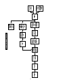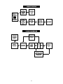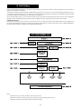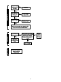
1
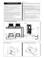
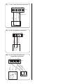
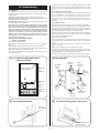
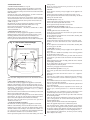
Bosch Group
28CDi RSF
WALL MOUNTED COMBINATION BOILER FOR CENTRAL HEATING
AND MAINS FED DOMESTIC HOT WATER
INSTALLATION AND
SERVICING INSTRUCTIONS
GC NUMBER 47 311 34 (N.G.)
GC NUMBER 47 311 35 (L.P.G.)
BOILER OUTPUT
Automatic Modulating Control
Minimum
Maximum
To Domestic Hot Water
9.0 kW
28.0 kW
To Central Heating
9.0 kW
24.0 kW
IMPORTANT: THESE INSTRUCTIONS APPLY IN THE UK ONLY
THESE INSTRUCTIONS ARE TO BE LEFT WITH THE USER OR AT THE GAS METER
This appliance must be installed by a competent person in accordance
with the Gas Safety (Installation and Use) Regulations 1994
Contents
1.
2.
3.
4.
5.
6.
7.
8.
9.
Installation Regulations .............................................. Page
General Information .................................................... Page
Technical Data .............................................................. Page
Siting the Appliance .................................................... Page
Siting the Flue Terminal .............................................. Page
Air Supply .................................................................... Page
Sealed Primary Systems ............................................ Page
Open Vent Primary Systems ...................................... Page
Domestic Hot Water .................................................... Page
2
2
4
5
6
6
7
8
8
10.
11.
12.
13.
14.
15.
16.
17.
18.
Electrical........................................................................ Page 9
Installation.................................................................... Page 12
Commissioning ............................................................ Page 16
Instructions to the User .............................................. Page 18
Inspection and Servicing ............................................ Page 18
Replacement of Parts .................................................. Page 19
Short Parts List ............................................................ Page 22
Operational Flow Diagrams........................................ Page 24
Fault Finding ................................................................ Page 27
Temperature safety cut-out controls.
A water flow regulator.
A standard horizontal flue assembly giving flue lengths from
100mm to 650mm.
An internal system filling link assembly.
An optional extra extension flue kits to provide for flue lengths
up to 3000mm.
Optional 45° and 90° Flue Bends.
Optional facia mounted electronic or mechanical programmers
and a radio controlled thermostat.
An optional open vent feed pipe assembly.
1. Installation Regulations
1.1 Gas Safety (Installation and Use) Regulations, October 1994
all gas appliances must be installed by a competent person in
accordance with the above regulations. Failure to install
appliances correctly could lead to prosecution.
1.2 The manufacturers notes must not be taken, in any way, as
overriding statutory obligations.
1.3 The compliance with a British Standard does not, of itself,
confer immunity from legal obligations. In particular the
installation of this appliance must be in accordance with the
relevant requirements of the Gas Safety (Installation and Use)
Regulations 1984 as amended, current IEE Wiring Regulations BS
7671, local Building Regulations, Building Standards
(Scotland)(Consolidation) and bylaws of the local Water
Company. Health and Safety Document No. 635 (Electricity at
Work Regulations).
It should be in accordance with the relevant recommendations of
the following British Standards.
BS 6798:1987 Specification for installation of gas fired hot water
boilers of rated input not exceeding 60 kW.
BS 5449:1990 Central Heating for Domestic Premises.
BS 5546:1990 Installation of gas hot water supplies for domestic
purposes.
BS 5440:1:1990 Flues and Ventilation for gas appliances of rated
input not exceeding 60 kW: Flues.
BS 5440:2:1989 Flues and Ventilation for gas appliances of rated
input not exceeding 60kW: Air Supply.
BS 6891:1988 Installation of low pressure gas pipework
installations up to 28mm (R1).
1.4 To ensure that the installation will perform to the highest
standards, the system and components should conform to any
other relevant British Standards in addition to those mentioned
in the instructions.
1.5 The advice and instructions given in this document covers, as
far as possible, the foreseeable situations which may arise. Contact
Worcester Heat Systems for advice on specific installations.
Fig. 1. Appliance water flow diagram.
Automatic
air vent
Gas to
water heat
exchanger
Boiler
Circulating
pump
Sealed
system
expansion
vessel
Water to
water heat
exchanger
Pressure
relief valve
Central
heating
by-pass
adjustment
Water
diverting
valve
2. General Information
CH DHW
flow out
2.1 This appliance is not suitable for external installation.
2.2 The appliance controls are set to provide a maximum output
of 28 kW for the domestic hot water and 24 kW for central
heating load.
2.3 The control circuit provides direct burner ignition. A pilot is
not used.
2.4 PRINCIPAL APPLIANCE COMPONENTS. See Fig. 1.
A low thermal capacity Gas to Water heat exchanger.
A Water to Water heat exchanger to provide domestic hot water.
Fully modulating controls in the central heating and domestic
hot water modes of operation.
An expansion vessel, pressure gauge and pressure relief valve.
A by-pass for the central heating system.
Mains CH Safety
cold return discharge
water in
2.5 ELECTRICAL SUPPLY
Mains supply: 230V ~, 50 Hz.
External fuse: 3A., Internal fuses: T 2A (F1), and T 1.25A (F2).
2.6 GAS SUPPLY
Check the data plate (located on the inner cover of the appliance)
to ensure the appliance has been set up for the correct gas
supply. The appliance can be set up for either of the following
gases: Natural gas (G20) or propane (G31). A conversion kit,
including instructions, is available to change the appliance
from one gas to the other.
2
The boiler requires 3.35 m3/h (115 ft3/hr) of natural (G20) or 1.29
m3/hr (46 ft3/hr or propane gas (G31). The gas meter and supply
pipes must be capable of supplying this quantity of gas in
addition to the demands of any other appliances being served.
The meter governor should deliver a dynamic pressure of 20
mbar (8in wg.) for natural gas or 37 mbar (14.4 in wg.) for
propane.
The complete installation, including the gas meter, must be
tested for soundness and purged. Refer to BS 6891.
2.7 PACKING
The appliance and flue components are packed in separate
cartons.
2.8 GENERAL INSTALLATION
The appliance is for connection to a sealed or open vented
primary system.
The specified ventilation openings made into a wall or
compartment door must not be obstructed.
If the appliance is to be fitted into a compartment then the
compartment must conform to the requirements of
BS.5440:2:1989.
Notwithstanding the instructions given in BS.5440:2:1989, this
appliance may be fitted in a compartment with no vents as long
as the minimum clearances stated in Section 6: Air Supply, are
maintained.
Do not place anything on top of the appliance.
The clearances specified for servicing must be maintained.
2.9 FLUE
The appliance has a multi-directional horizontal fanned flue
system.
The standard flue assembly length is from 100mm to 650mm.
Extension flue lengths available are from 651mm to 3000mm.
A terminal guard, Type K2, GC 393 553, is available from Tower
Flue Components, Vale Rise, Tonbridge,TN9 1TB.
Do not allow the flue terminal fitted to the outside wall to
become obstructed or damaged.
A kit for internal fixing of the flue is available separately.
2.10 CONTROLS
The electronic control system and gas valve modulate the heat
input in response to the central heating and domestic hot water
temperature settings between minimum and maximum.
The ON/OFF switch will turn the mains electricity on and off to
the appliance.
The Central Heating Temperature control knob provides for the
selection of domestic hot water only (Turned fully anti-clockwise)
or central heating and domestic hot water (Turned clockwise).
Facia mounted programmers are available as an optional extra.
A remote mounted programmer may be connected to the
appliance.
The integral facia displays indicate the status of the appliance.
There is provision for the connection of a mains voltage room
thermostat and/or a frost thermostat.
The electronic controls prevent rapid cycling of the appliance in
the central heating mode.
2.11 SYSTEM NOTES
IMPORTANT
Check that no dirt is left in either the gas or water pipework as
this could cause damage to the appliance. Thoroughly flush the
heating system and the cold water mains supply in accordance
with the recommendations of BS7593: 1992
Purge the gas supply before finally connecting the appliance.
The water pipe connections throughout a sealed system must be
capable of sustaining a pressure of up to 3 bar.
Radiator valves must conform to the requirements of BS 2767 1991.
The relief valve discharge must be directed away from any electrical
components or where it would cause a hazard to the user.
A drain cock to BS 2879 must be fitted to the lowest point of the
system.
Fig. 1a.
IMPORTANT:
After flushing out all
pipework and before
mounting the appliance
please ensure that the
water inlet filter contained
in the fixing kit is fitted as
shown.
Inlet water
filter
Cold water
inlet on
diverter valve
For circuit design purposes it is important that due note is taken of
the information given in Table 3 relating to the available pump head.
2.12 SHOWERS, BIDETS, TAPS AND MIXING VALVES
Hot and cold taps and mixing valves used in the system must be
suitable for operating at mains pressure.
Thermostatically controlled shower valves will guard against the
flow of water at too high a temperature.
If using a pressure equalising valve, set the Domestic Hot Water
temperature control knob to the ‘MAX’ position.
Hot and cold mains fed water can be supplied direct to an overrim flushing bidet subject to local Water Company requirements.
With all mains fed systems the flow of water from the individual
taps will vary with the number of outlets operated
simultaneously and the cold water mains supply pressure to the
property. Flow balancing using ‘Ball-o-Fix’ type valves is
recommended to avoid an excessive reduction in flow to
individual outlets. For further information contact Worcester
Heat Systems Ltd.
2.13 SAFETY CONSIDERATIONS
The appliance must not be operated in a waterless condition.
The appliance must not be operated with the boiler inner casing
cover removed.
Work must not be carried out on the appliance without the gas
and electricity supplies being switched off.
Checks must be made to ensure that the ventilation openings
made into walls and partitions are of the correct size and are not
obstructed.
2.14 OPERATION
Domestic Hot Water: With a demand for hot water the burner
will light at its maximum setting and then automatically adjust
its output to maintain the temperature of the delivered water.
When hot water is no longer required, the burner will extinguish.
The fan and pump may continue to run for a short period to
dissipate the residual heat from the appliance.
Central Heating: With a demand for heating the burner will light
at its minimum setting and gradually increase to give the
maximum output. The output of the appliance is then
automatically adjusted to maintain the temperature of the
system. The output can reduce down to a minimum of 9.0 kW. If
the system no longer requires even the minimum output to
maintain the desired room temperature the burner will
extinguish. The fan and pump may continue to run to dissipate
the residual heat from the appliance. The appliance will remain
off for a fixed period of three minutes before re-lighting to
automatically meet the system requirements.
Domestic Hot Water and Central Heating: The appliance will
supply heat to the central heating system as required. A demand
for domestic hot water at a tap or shower will override the
central heating requirement for the period of the domestic hot
water demand. When hot water is no longer required the
appliance will return to the central heating state and its normal
mode of operation. The fan may continue to run to dissipate the
residual heat from the appliance as necessary.
3
The data plate is fixed to the inner casing cover. Check data plate
to ensure appliance has been adjusted for supply gas.
3. Technical Data
Table 1
Btu/h
(30,700)
(81,888)
(95,536)
NOMINAL BOILER RATINGS (10 Minutes After Lighting)
BOILER ADJUSTED FOR G20 (Natural Gas)
BURNER SETTING
INPUT
PRESSURE
kW
Btu/h
m bar.
in. wg.
11.4
(38,897)
1
0.4
27.0
(92,124)
8.8
3.5
31.5
(107,478)
12.1
4.8
3
m /h
1.2
2.9
3.3
ft3/h
42.5
102.7
116.9
(30,708)
(81,888)
(95,536)
BOILER ADJUSTED FOR G31 (Propane)
(38,897)
3.8
(92,124)
24.3
(107,478)
35.5
0.5
1.1
1.3
17.7
38.9
46.0
OUTPUT
kW
9.0
24.0
28.0
9.0
24.0
28.0
11.4
27.0
31.5
GAS RATE
1.5
9.6
14
Table 2.
FLUE DETAILS
HORIZONTAL FLUE
WALL HOLE DIAMETER
STANDARD FLUE – MINIMUM LENGTH
STANDARD FLUE – MAXIMUM LENGTH
EXTENDED FLUE – MAXIMUM LENGTH
mm
110
100
650
3000
inches
4.25
4.0
25.6
118.1
Table 3
AVAILABLE PUMP HEAD
BOILER OUTPUT
kW
9.0
24.0
Btu/h
(30,700)
(81,900)
HEAD
Metres
4.2
2.0
MIN. FLOW RATE
Feet
13.6
6.6
L/min.
11.7
28.5
Gal/Min.
2.57
6.3
TEMPERATURE RISE
ACROSS HEATING
FLOW AND RETURN
11°C (20°F)
12°C (22°F)
Table 4
SPECIFICATIONS
CENTRAL HEATING FLOW FITTING
CENTRAL HEATING RETURN FITTING
COLD WATER MAINS INLET FITTING
DOMESTIC HOT WATER OUTLET FITTING
GAS INLET FITTING
PRESSURE RELIEF VALVE DISCHARGE FITTING
OVERALL HEIGHT (including flue turret)
CASING HEIGHT
CASING WIDTH
CASING DEPTH
WEIGHT(including water)
INSTALLATION WEIGHT
PACKAGED WEIGHT
PRIMARY WATER CAPACITY
MAXIMUM COLD SUPPLY PRESSURE
MINIMUM COLD SUPPLY PRESSURE (working) for max. hot water flow
MINIMUM COLD SUPPLY PRESSURE (working) to operate appliance
MAXIMUM CENTRAL HEATING FLOW TEMPERATURE
OUTPUT TO DOMESTIC HOT WATER
OUTPUT TO CENTRAL HEATING
MAXIMUM DOMESTIC HOT WATER FLOW RATE (from the appliance)
EQUIVALENT DOMESTIC HOT WATER FLOW RATE TO GIVE A TEMP RISE
OF 30°C (SPECIFIC RATE)
NoX Classification
4
22mm Compression
22mm Compression
15mm Compression
15mm Compression
Rp 3⁄4 inch
G 1⁄2 inch
1000mm (39.4 inches)
850mm (33.5 inches)
450mm (17.7 inches)
360mm (14.2 inches)
45 kg
42 kg
48 kg
2.0 litres (0.45 galls)
10 Bar (150 psi)
1.2 bar
0.7 bar
Nominally 82°C (180°F)
Modulating 9.0 to 28 kW
Modulating 9.0 to 24 kW
Nominally 10 litres/min
Nominally 13.5 litres/min
Class 3
Notwithstanding the instructions given in BS 5440:2, this
appliance may be fitted in a compartment with no vents as long
as the minimum clearances stated in Section 6: Air Supply, are
maintained.
4.7 The airing space must be separated from the boiler space by
a perforated non-combustible partition. Expanded metal or rigid
wire mesh are acceptable provided that the major dimension is
less than 13mm. See BS 6798:1987.
4.8 No combustible surface must be within 75mm of the casing.
See BS476:4.
4.9 The distance between the inner face of a cupboard door and
the cabinet front should not be less than 75mm.
4.10 Always consider the possible need to disconnect the pipes
from the appliance after installation.
4.11 LPG Installation: The appliance shall not be installed in a
room or internal space below ground level when it is intended for
use with LPG. This does not preclude the installation into rooms
which are basements with respect to one side of the building but
open to ground level on the opposite side.
4. Siting The Appliance
4.1 The appliance may be installed in any room although
particular attention is drawn to the requirements of the current
I.E.E. Wiring Regulations BS 7671 and, in Scotland, the electrical
provisions of the Building Regulations applicable in Scotland,
with respect to the installation of appliances in rooms containing
baths or showers.
Where a room sealed appliance is installed in a room containing
a bath or shower, any electrical switch or appliance control using
mains electricity must not be able to be touched by a person
using the bath or shower.
4.2 The appliance is not suitable for external installation.
4.3 The appliance does not require any special wall protection.
4.4 The wall must be capable of supporting the weight of the
appliance. See Table 4.
4.5 The following clearances must be available for installation
and for servicing. See Fig. 2.
4.6 The appliance can be installed in a cupboard used for
airing clothes provided that the requirements of BS 6798 and
BS 5440:2 are met.
Installation
Service
30mm
30 mm
In front
600 mm
600 mm
Below
200mm
200mm
Right-hand side
10 mm
10 mm
Left-hand side
10 mm
10 mm
Above the flue turret
Fig. 3. Appliance pipework connections.
Fig. 2. Appliance casing dimensions and
required clearances.
(A)
(B)
30mm*
61
91
(C)
(D)
180mm
(E)
(F)
Side view
360mm
Front view
600mm*
200mm*
850mm
225mm
A
B
C
D
E
F
450mm
10mm*
10mm*
* Space required for installation and servicing
5
CH Flow
DHW Out
Mains Cold Water In
Gas Inlet
CH Return
Safety Relief
=
=
=
=
=
=
62.5
127.5
192.5
257.5
322.5
382.5
5. Siting The Flue Terminal
6. Air Supply
See Fig. 4
6.1 The appliance does not require a separate vent for
combustion air.
6.2 The appliance can be fitted in a cupboard with no vents for
cooling but the minimum clearances must be increased to those
given below. (Note: The clearances at the front are for a removable
panel, e.g. a door).
5.1 The flue must be installed as specified in BS 5440:Part 1.
5.2 The terminal must not cause an obstruction nor the
discharge cause a nuisance.
5.3 If the terminal is fitted within 1000mm of a plastic or painted
gutter or within 500mm of painted eaves then an aluminium
shield at least 1000mm long should be fitted to the underside of
the gutter or painted surface.
Above the flue turret
In front
Below
Right-hand side
Left-hand side
5.4 If a terminal is fitted less than 2 metres above a surface to
which people have access then a guard must be fitted. See
Section 2.9.
30mm
250mm
200mm
75mm
75mm
6.3 If the appliance is to be fitted in a cupboard or compartment with
less clearance than those in the table above (minimum clearances are
given in Section 4. Siting The Appliance) then permanent air vents for
cooling are required. One at high level and one at low level, either
direct to outside air or to a room. Both vents must pass to the same
room or be on the same wall to the outside air.
6.4 The minimum free areas required are given below.
5.5 The terminal guard must be evenly spaced about the flue
terminal and fixed to the wall using plated screws.
5.6 In certain weather conditions a terminal may steam and
siting where this could cause a nuisance should be avoided.
5.7 Take care to ensure that combustion products do not enter
ventilated roof voids.
POSITION OF
AIR VENTS
HIGH LEVEL
LOW LEVEL
AIR FROM
THE ROOM
315 cm2
315 cm2
AIR DIRECT
FROM OUTSIDE
158 cm2
158 cm2
6.5 Refer to BS 6798 and BS 5440:2 for additional information.
Fig. 4. Siting of the flue terminal.
TERMINAL POSITION
MIN. DISTANCE
A– directly below an openable window or
other opening e.g. air brick.
B– Below gutters, soil pipes or drain pipes.
C– Below eaves.
D– Below balconies or car port roof.
E– From vertical drain pipes and soil pipes.
F– From internal or external corners.
G– Above ground, roof or balcony level.
H– From a surface facing a terminal.
I– From a terminal facing a terminal
J– From an opening in a car port (e.g. door
window) into dwelling.
K– Vertically from a terminal on the same
wall.
L– Horizontally from a terminal on the same
wall.
M– From door, window or air vent (achieve
where possible).
300 mm (12 in.)
75 mm (3 in.)
25 mm (1 in.)
25 mm (1 in.)
25 mm (1 in.)
25 mm (1 in.)
300 mm (12 in.)
600 mm (24 in.)
1200 mm (47 in.)
1200 mm (47 in.)
150 mm (6 in.)
300 mm (12 in.)
150 mm (6 in.)
A
L
G
B,C
K
L
D
K
F
F
HI
A
F
J
E
G
M
6
fitted as shown).
Insert the bayonet end of the filling key into the corresponding
cut outs in the filling loop housing and twist to lock the key in
place.
Turn the grey knob anti-clockwise to allow water ingress and fill
until the required pressure is reached.
Turn the grey knob clockwise to stop filling and remove the filling
key by lining up the bayonet end of the key with the cutouts in
the filling loop housing and withdrawing the key.
N.B. The key must always be removed from the filling loop
housing after the system has been filled to prevent accidental
filling and to comply with Byelaw 14 of the Water Byelaws
Scheme.
Store the key in a safe place for future use and refit the bottom
panel.
7.10 Repeated venting loses water from the system. It is
essential that this water is replaced and the system pressure
maintained.
7.11 Connections to the mains water supply must not be made
without the authority of the local Water Company.
7.12 The pump is set at maximum and must not be adjusted.
7.13 Connections in the system must resist a pressure of up to 3 bar.
7.14 Radiator valves must conform to BS 2767:10.
7.15 Other valves used should conform to the requirements of
BS 1010.
7. Sealed Primary Systems
See Figs. 5, 6 and 6a.
7.1 The system must comply with the requirements of BS 6798
and BS 5449.
7.2 The appliance must not be operated without the system
being full of water, properly vented and pressurised.
7.3 The pressure relief valve operates at 3 bar (45lb/in2). The
discharge must be directed away from electrical components or
where it might be a hazard to the user.
7.4 The pressure gauge indicates the system pressure which
must be maintained.
7.5 The 10 litre expansion vessel is charged to 0.5 bar and is
suitable for a static head of 5 metres (17.5ft). The pressure can be
increased if the static head is greater than 5 metres (17.5ft).
7.6 With an initial system pressure of 0.5 bar, a system capacity
of about 83 litres can be accommodated. Refer to BS 7074 Pt. 1
for more information. The charge pressure can be increased but
with a decrease in system volume.
7.7 The appliance includes a system filling link.
7.8 Water loss must be replaced.
7.9 Filling the System. (See Fig. 6 and 6a). Remove the bottom
panel to gain access to the filling loop assembly. (The grey knob
for the filling loop is packed in the hardware pack and should be
Fig. 5. Sealed primary water system.
Automatic
air vent
Mains cold
water
Expansion
vessel
Radiator
valve
Lockshield
valve
Hot water out
Heating
return
Heating
flow
NOTE: A drain cock should be installed at
the lowest point of the heating circuit and
beneath the appliance.
British Standard
stop valve.
Fixed spindle type
Water main
Fig. 6a. Filling Key inserted for filling.
Fig. 6. Filling Loop.
Grey filling
knob
Filling Key
Always remove key
after filling
7
8.4 A pressure relief valve is not required on an open vented
system.
8. Open Vent Primary Systems
8.5 Air within the appliance will be expelled via the feed and
vent connection or dissipated into the rest of the system which
must be fitted with manual air vents at any high point.
8.1 The size of the flow and return pipework is given in Section 3
– Table 4. The components required to connect the appliance to
an open vent system are available as an optional extra kit.
8.2 The feed and expansion cistern should be arranged so that
there is a minimum static head of 0.3 metres (12 inches) above
the top of the appliance or above the highest point in the heating
circuit, whichever is the higher. See fig. 7
8.3 The feed and vent pipe should be 22mm diameter and rise
continuously from the appliance to the feed and expansion
cistern.
8.6 The pump is set to maximum and must not be reset.
8.7 If it is required to use the appliance for domestic hot water
before the central heating circuit is connected, a 22mm copper
by-pass must be connected between the central heating flow
and return. Refer to Section 12.
Fig. 7. Open vent water system.
Static Head (S.H.): Minimum static
head 0.3m (12in) measured from the top
surface of the appliance or the highest
point in the heating system to the water
level in the feed and expansion tank.
Stop valve
S.H.
Combined feed and
vent pipe (22mm),
must rise continuously
S.H.
Open vent pipe
(supplied as
optional extra)
Mains
cold
water
Radiator
valve
Lockshield
valve
Hot water out
Heating
return
Heating
flow
NOTE: A drain cock should be installed at the lowest
point of the heating circuit and beneath the appliance.
British Standard
stop valve.
Fixed spindle type
Water main
9.9 Hot and cold taps and mixing valves used with this
appliance must be suitable for operating at mains pressure and
temperatures of 65°C.
9.10 No anti-syphonage arrangements are necessary except for
some loose head showers. See also Section 9.11 following.
9.11 Thermostatically controlled or pressure equalising shower
valves will guard against the flow of water at too high a
temperature.
9.12 The head of a loose head shower must not fall closer than
25mm (1in) above the top edge of the bath to prevent its immersion
in bath water. Alternatively the shower must be fitted with an antisyphonage device at the point of the flexible hose connections.
9.13 The supply of hot and cold mains water direct to a bidet is
permitted, (subject to local Water Company requirements),
provided that the bidet is of the over-rim flushing type. The
outlet(s) should be shrouded and unable to have any temporary
hand held spray attached. No anti-syphonage arrangements are
necessary.
9.14 As the maximum temperature of the Water to Water heat
exchanger is limited by the control circuit, there is normally no
need for water treatment to prevent scale accumulation. In
exceptional circumstances a device to prevent scale formation
can be fitted.
Installation of a scale inhibitor assembly should be in
accordance with the requirements of the local Water Company.
An isolating valve should be fitted to allow servicing. The water
hardness can be determined using a standard test paper or by
reference to the local Water Company.
9. Domestic Hot Water
9.1 The following are general requirements and, if necessary,
reference should be made to the local Water Company before
fitting the appliance.
9.2 MAINS COLD WATER INLET. Devices capable of preventing
the flow of expansion water must not be fitted unless separate
arrangements have been made. An expansion vessel connection
point is provided within the appliance.
An Rc1/2” connection is provided. A Zilmet Z160 is the preferred
type. A thread sealant compatible with potable water must be
used.
9.3 The final 600mm of the mains cold water connection to the
appliance should be made in copper tube only.
9.4 The appliance is suitable for a mains pressure of up to 10 bar
(150 lb/in2).
9.5 The appliance is fitted with a mains supply isolating valve.
9.6 The maximum domestic hot water flow rate is 10 litres/min
(±15%) (2.2 gallons/min).
9.7 In winter (when the mains inlet water temperature is lower) a
reduced flow rate at the taps may be required to achieve the
type of hot water delivery temperature available in warmer
weather.
9.8 It is suggested that long pipe runs to the taps or shower
should be insulated to prevent the rapid cooling of domestic hot
water after a tap or shower has been turned off.
8
10.10 The boiler is fitted with an internal frost thermostat which
will protect the boiler from frost damage, as long as the mains
switch on the boiler is in the on position. However, if frost
protection is necessary for the system, please contact Worcester
Heat Systems Technical Helpline. Tel: 0990 266241.
10.11 SAFETY CHECK.
After installation or in the event of an electrical fault the
electrical system shall be checked for short circuits, fuse failure,
incorrect polarity of connections, earth continuity and resistance
to earth.
10. Electrical
See Figs. 8, 9, 10, 11, 12 and 13.
10.1 MAINS SUPPLY.
230 V ~, 50 Hz, 180 watts.
External Fuse: 3A. Internal Fuses: T 2A (F1), and T 1.25A (F2).
Spare internal fuses are supplied at the rear of the facia, next to
the pressure gauge.
10.2 It must be possible to completely isolate the appliance.
10.3 The following connection alternatives must be used:
A 3 amp fused three-pin plug and unswitched shuttered socket
outlet (both complying with the requirements of BS 1363) or a
double pole isolator with a contact separation of 3mm in all
poles and supplying the appliance and controls only.
10.4 The appliance must be earthed.
10.5 Mains Cable. 0.75mm2 (24 x 0.20mm) to BS 6500 Table 16.
The mains cable must be connected into the terminal ST12,
marked L (Brown or Red lead), N (Blue or Black lead) and the
earth stud and be held securely in the cable clamp. For access
undo the three bottom screws and remove the facia access cover.
See Fig. 23.
10.6 The wiring between the appliance and the electrical supply
shall comply with current IEE Wiring Regulations and any local
regulations which apply.
10.7 If a room thermostat and/or external programmer is to be
fitted refer to Figs 11, 12 and 13. The devices must be suitable for
use with mains voltage.
10.8 Facia mounted programmers are available as optional
extras. Instructions are supplied with the programmer kits.
10.9 A time switch or programmer can be fitted externally to the
appliance.
Fig. 8. Mains electricity connections.
230V
L N Ns LS LR
ST12
Brown
Blue
n
ow
Br
Gr
ee
n/y
ell
Blue
ow
Strain relief clamp
Fig. 9. Wiring diagram.
Green/yellow
Fan electrical connections
Black
1
White
4
Red
3
Fan
CH sensor
Overheat
cut-off
device
Flame sense
electrode
Spark
electrode
Gas valve
Reg
Main
2
Pump
Air pressure
switch
3
Main
DHW
sensor
Spark
transformer
Flow
switch
Mains in
black
white
red
Link
ST16
ST15 ST1
blue
brown
ST8
blue
ST12
brown
Control Board
9
1
2
pink
2 yellow
2 green
2 red
white
2 blue
2 orange
2 brown
2 violet
LIVE
IN
ST12 Pin N
ST12 Pin L
Fuse F1
(2A Slow)
On/Off
switch
10
ST1
Centre
Pin
Low
High
ST1
Pin L
Convert AC to low
voltage electronics
ST15
Pin L
REL
4
ST8
(LR)
Spark
Indicators
Red
Settings
Red
DHW
CH
demand demand
indicator indicator
Electronics/
microprocessor
(Safety Low Voltage)
REL 3
Optional link
Room
thermostat
ST8
(NS)
Transformer
Fuse F2
(1.25A Slow)
Spark
electrodes
Red
Flame
detect
indicator
Outputs
REL 1
ST8
(LS)
Electronics
green
Mains
indicator
Inputs
N
N
24V programmer
Overheat cut-off
Flame sense
Air pressure switch
DHW sensor
CH sensor
Flow switch
Main valve
Main valve
Regulator valve
Fig. 10. Functional flow diagram.
DHW control knob
CH Control knob
CH pressure adjust pot
Gas valve mode switch
Reset button
Electronics
Electronics
Electronics
(2 speed)
Fan
Pump
Fig. 11. 230 V room thermostat connections.
NS
LS
LR
Spare
Remove link
Switched live
Live
Neutral
ST8
Fig. 12. 230 V programmer connections.
NS
LS
LR
Spare
Switched live
Live
Neutral
ST8
Motor
Fig. 13. 230 V room thermostat and
programmer connections.
LS
NS
LR
Spare
tche
d liv
Swi
Live
Neutral
ra
e
ut
liv
Ne
d
he
tc
ve
Li
i
Sw
e
ST8
l
Motor
11
Flue components
1. Appliance casing sealing gasket
2. Flue Turret
3. Flue Collar
4. Air duct to turret sealing ring
5. Standard air duct
6. Standard flue duct
7. Restrictor ring
8. Flue terminal
9. Extension air duct
10. Extension flue duct
11. Flue duct sealing ring
12. In-line flue elbow
13. Vertical flue adaptor
11. Installation
The appliance is supplied suitable for fitting to a sealed system. If
it is to be fitted to an open vent system refer to section 8.
11.1 FLUE OPTIONS.
The standard flue length is from 100mm to 650mm measured
from the appliance casing to the outer wall.
Extension flue kits, a vertical take-off adaptor, 90° flue bends
and 45° flue bends are available to increase the length and
redirect the flue as follows.
The maximum flue length is 3000mm.
For each added 90° flue bend 1000mm of flue must be
removed.
IMPORTANT:
The restrictor ring must not be used for flue lengths over
650mm
For each added 45° flue bend 500mm of flue must be removed.
The flue turret can be replaced by a flue bend with no reduction
in flue length.
The flue must be installed as specified in BS 5440 Part 1.
Fig. 14. Fixing the wall mounting plate.
drill lower
pair of holes
in cross
brace
Fig. 16. Flue turret fixing and automatic
air vent.
Top fixing
screws (2)
Plumbing
manifold Mark horizontal
line along here
fixing
screws (4)
822mm
800mm
211mm
Fixing screws (4)
Flue turret
Auto air vent
Sealing
gasket
Pre-plumbing
manifold
Flue gas
test point
99mm
425mm
Fig. 15. Fixing the appliance to the wall mounting plate.
Appliance
Wall mounting plate
Step 2. Secure at top
with the M6 nuts and
washers supplied (2).
Keep appliance
vertical
Step 1. Rest appliance on
wall mounting plate and push
back, engaging valves first.
12
Step 3. Secure
at bottom with
caps and bolts
supplied (3).
NOTE: READ THIS SECTION FULLY BEFORE COMMENCING
INSTALLATION
11.2 GENERAL FITTING.
Check that the appliance carton contains: Appliance, installers
instruction pack, pre-plumbing manifold, wall plate cross
member, user’s information pack and installer’s hardware pack.
Assemble the wall plate cross member to the pre-plumbing
manifold as shown in Fig. 14 using the two M4 thread forming
screws supplied in the hardware pack.
Check that the position chosen for the appliance is in accordance
with the instructions given in Sections 4 and 5.
Hold the wall plate to the wall. Check that the plate is horizontal.
See Fig. 14.
Leave the pre-fitted plastic cover in place to protect the valves
and ‘O’ rings from dust and dirt during installation.
Mark the position of the fixing holes and the position of the flue
hole centre line onto the wall. Draw a horizontal line along the
top of the wall plate cross member as shown in Fig. 14.
Rear Flue – Mark a vertical line through the flue hole centre point.
Measure upwards 800mm from the horizontal line and mark the
point. This is the centre point of the flue duct hole. See Fig. 16.
Side Flue – Extend the horizontal line from Fig. 14 along the
appropriate wall. Check that it remains horizontal and measure
800mm upwards and mark a horizontal line. Measure 197mm
from the junction of the walls and mark a vertical line which will
then give the position of the flue hole.
Drill the six fixing holes 60mm deep for No. 12 size plugs. Cut
the flue duct hole at 110mm diameter (150mm dia. for internal
fitting). Ensure that the hole is horizontal through the wall.
Fix the wall plate and check that it is horizontal before tightening
the six screws.
Connect the gas, water and pressure relief valve connections to
the manifold. The primary system should be flushed and treated
in accordance with the recommendations of BS 7593:1992.
Remove the plastic cover from the manifold, and make sure that
the “O” rings are fitted clean and lubricated.
Slide the appliance onto the pre-plumbing manifold ensuring
that the three pegs are located correctly. Secure with the two M6
nuts and washers at the top and screw the appliance to the
manifold at the bottom, using the three retaining caps and M6
bolts. See Fig. 15.
Access to these pegs and caps can be made easier by removing
the bottom panel.
Unscrew the automatic air vent cap. See Fig. 16.
If the air and flue duct assembly is to be fitted from inside the
room then the ducts must be cut to length, assembled and
inserted through the wall at this stage before fitting the flue
elbow to the appliance. Refer to Section 11.3 following for the
assembly of the air and flue ducts.
Remove the fan. See Section 14.3(e).
11.3 AIR AND FLUE DUCT PREPARATION AND ASSEMBLY
Check the contents of the standard flue duct kit against the
packing list. Similarly check the extension duct kits if applicable.
Remove all the packing from the ducts and terminal assembly.
The standard flue kit accommodates a flue assembly up to
650mm long measured from the appliance casing to the outer
wall face. See dimension L, Figs.17 and 18. When dimension L is
greater than 650mm extension flue assemblies will be required.
Measure and cut the air and flue ducts to length ensuring that
the cuts are square and free from burrs. Always check the
dimensions before cutting the ducts.
Fit the restrictor ring in the flue terminal only when the overall
length of the flue is less than 1000mm and no additional flue
bends have been fitted.
11.4 EXTERNAL FITTING OF THE DUCT ASSEMBLY
Rear Flue Assembly
Measure distance L. See Fig. 17.
Air duct length = L + 146mm.
Flue duct length = L + 181mm.
Do not cut the drilled end of either duct.
Assemble the air and flue ducts to the terminal. Drill through the
holes in the terminal into the air duct and fix using the screws
provided. See Fig. 22. Join the extension ducts to the standard
ducts as indicated in Fig. 20, making sure the seal is in place.
Drill and screw together the air ducts.
From outside, push the assembly through the wall and enter the
ducts into the flue outlet turret.
Pull back the air duct slightly to allow access to the flue duct.
Drill through the flue duct and fix with the screws provided. Push
the air duct into the turret. Drill and fix the air duct to the turret.
See Fig. 19.
Align the flue turret with the 4 holes on the appliance and screw
down. See Fig. 16.
Make good the internal and external brickwork or rendering.
Refit the fan. Do not use any sealant on the joint. Replace the
inner casing cover.
Side Flue Assembly
Measure distance L. See Fig. 18.
Air duct length = L + 175mm.
Flue duct length = L + 210mm.
Do not cut the drilled end of either duct.
Assemble the air and flue ducts to the terminal. Drill through the
holes in the terminal into the air duct and fix using the screws
provided. See Fig. 22. Join the extension ducts to the standard
ducts as indicated in Fig. 20, making sure the seal is in place.
Drill and screw together the air ducts.
From outside, push the assembly through the wall and enter the
Fig. 18.
Fig. 17. Flue duct length (rear flue).
Flue duct length (side flue).
Make good
Make good
10mm
10mm
External
wall face
External
wall face
Rear face of appliance
and face of mounting
wall
Appliance side
panel
L
L
13
Fig. 19. Flue elbow, ducts and terminal
assembly
Fig. 21. Terminal assembly for internal
fitting of the flue.
Flue duct length =
L + 181mm (rear flue)
L + 210mm (side flue)
Rubber sealing
gasket
Air duct length =
L + 146mm (rear flue)
L + 175mm (side flue)
Fixing
screws
Flue terminal
Clamping ring
Restrictor
ring
Seal these
joints
Appliance
casing
Flue
terminal
L
Fig. 20. Flue assembly using extension kits.
Flue duct length = L + 181mm (rear flue)
L + 210mm (side flue)
Air duct length
= L + 146mm (rear flue)
L + 175mm (side flue)
Fixing
screws
Standard flue duct
Flue duct extension
Flue duct seal
Seal these
joints
Air duct extension
Flue terminal
Appliance
casing
L
ducts into the flue outlet turret.
Pull back the air duct slightly to allow access to the flue duct.
Drill through the flue duct and fix with the screws provided. Push
the air duct into the turret. Drill and fix the air duct to the turret
with the screws provided. See Fig. 19.
Align the flue turret with the 4 holes on the appliance and screw
down. See Fig. 16.
Make good the internal and external brickwork or rendering.
Refit the fan. Do not use any sealant on the joint. Replace the
inner casing cover.
Fig. 22. Duct and terminal assembly for
internal fitting of the flue.
Flue centring ring
Air duct
Standard air duct
Flue terminal
11.5 INTERNAL FITTING OF THE DUCT ASSEMBLY
The rubber sealing gasket and the clamping ring are available
from Worcester Heat Systems.
Measure and cut the ducts as previously described for external
fitting (Section 11.4). Fix the ducts to the terminal and fit the
rubber sealing gasket and clamp to the terminal. Centralise the
gasket and tighten the clamping ring. See Fig. 21. Slide the flue
centering ring onto the air duct and tighten the screw. See
Fig. 22. Fix the ducts and terminal assembly to the flue turret
as described in Section 11.4 preceding.
Push the assembly through the wall so that the gasket flange is
against the outside face of the wall. See Fig. 22.
Flue duct
Rubber
sealing
gasket
14
tightened.
If a facia mounted programmer is to be fitted follow instructions
with the programmer..
Hinge down the facia as described in Section 14.3(c).
Connect the mains electrical supply to the appliance at terminal
ST 12 See Fig. 8. Connect any room and/or frost thermostats.
The electrical leads must pass through the appropriate space in
the control panel and be fixed with the cable clamps provided.
See Figs. 11 and 12. Refit the facia panel.
Test the gas supply pipework up to the appliance for soundness
as indicated in BS 6891.
Refer to Section 12 for a full description of the filling, venting and
the pressurising of the system.
If the appliance is not to be commissioned immediately, replace
the cabinet front panel. Check that the gas supply, the electrical
supply and the water connections are all turned off.
If the premises are to be left unoccupied during frosty
conditions, then drain the appliance and system. For short
inoperative periods, leave the appliance under the control of
the built in frost thermostat or the remote frost thermostat (if
fitted) or leave operating continuously with the room
thermostat set at 6°C.
Align the flue turret with the 4 holes on the appliance and screw
down. See Fig. 16.
Refit the fan. Do not use any sealant on the joint. Replace the
inner casing cover.
Seal the gap around the duct with the flexible seal provided and
make good. See Fig. 22.
11.6. FITTING FLUE BENDS
Flue bends are an optional extra, the 90° bend supplied
singularly and the 45° bends being supplied as a pair. The bends
can be fitted in any combination as long as the combined
equivalent flue length plus length of flue duct does not exceed
3000mm. One 90° bend is equivalent to 1000mm of flue duct
and one 45° bend is equivalent to 500mm of flue duct. See Fig.
22a. In between flue bends (or between first bend and vertical
take-off adaptor) there is no difference in the length of the air
duct and the flue duct. Between the first bend and the flue turret
the air duct needs to be 14mm longer than the flue duct. After
the last bend the flue duct needs to be cut 15mm longer than
the air duct to fit into the terminal. Note the swaged ends of the
air ducts and the flue ducts must be removed to connect into the
flue bends and all joints between bends and flue must be sealed
with silicone sealant.
11.7 FINAL INSTALLATION
Check that all the water and gas connections have been
Fig. 22a. Fitting the flue bends to the intermediate sections of the flue duct.
Flue duct L3
+ 15mm
Air duct L3
Flue and air duct = L2
Air duct L3
Flue duct L1
Ð 14mm
Air duct L1
Flue duct L3
+ 15mm
r
ai
d 2
an = L
ue t
Fl duc
Flue duct L1
Ð 14mm
Air duct L1
15
Check that the pressure relief valve operates by turning the knob anticlockwise until it releases. Water should be expelled from the discharge
pipe. See Fig. 24. Lower the control box to gain access. Refer to Section
14.3(c).
Set the Expansion Vessel Pressure
The charge pressure of the expansion vessel as dispatched is 0.5 bar,
which is equivalent to a static head of 5 metres (17 ft). The charge
pressure must not be less than the static head at the point of
connection. See Fig. 7. A Schraeder type tyre valve is fitted to the
expansion vessel to allow the charge pressure to be increased if
necessary.
Set the System Pressure
Remove the bottom panel to gain access to the filling loop assembly.
Insert the bayonet end of the filling key into the corresponding cut outs
in the filling loop housing and twist to lock the key in place. (see fig. 26)
Turn the grey knob anti-clockwise to allow water ingress and fill the
system untill the pressure gauge shows 2.5 bar (37 lb/in2).
Turn the grey knob clockwise to stop filling and remove the filling key
by lining up the bayonet end of the key with the cutouts in the filling
loop housing and withdrawing the key.
Check for water soundness.
Release water from the system using the relief valve test knob (see fig.
24), untill the system design pressure is obtained, up to a maximum of
1.5 bar.
Initial system design pressure (bar) = Expansion vessel charge
pressure + 0.3 bar.
NOTE: 1 bar is equivalent to 10.2 metres (33.5 ft) of water.
N.B. The key must always be removed from the filling loop housing
after the system has been filled to prevent accidental filling and to
comply with Byelaw 14 of the Water Byelaws Scheme.
Store the key in a safe place for future use and refit the bottom panel.
12. Commissioning
12.1 SUMMARY
The appliance is dispatched with the controls set to provide a
maximum output for domestic hot water of 28 kW and 24 kW for
central heating.
The appliance automatically modulates to satisfy lower heat loads.
Domestic Hot Water System. Check that the mains water supply has
been fully flushed out at installation.
Central Heating System. Check that the central heating system has
been fully flushed out at installation.
Gas Service. The complete system, including the meter, must be
inspected and tested for soundness and purged as indicated in BS
6891. In the event of a leak, or suspected leak, on the ‘O’ ring joint
on the main appliance manifold, we recommend that a manometer
is attached to the test point on the inlet of the multifunctional gas
valve and a soundness test carried out after turning off the
appliance gas cock; this will test the section between the gas cock
and the gas valve, thus enabling the leak to be traced to either a
visible joint or to the ‘O’ ring.
12.2 APPLIANCE AND CENTRAL HEATING
SYSTEM – PREPARATION
Remove the cabinet front panel.
Check that the electrical supply and the gas service to the appliance
are off.
Check that all the water connections throughout the system are tight.
Open the system valves at the appliance. Open all the radiator valves,
fill the system and vent each radiator in turn.
The automatic air vent will vent the appliance. Check that the air vent
cap has been loosened.
Fig. 23. Appliance casing and control
equipment fixings.
Inner casing cover
fixing screws (4)
Fig. 25. Gas valve.
Modulating
solenoid
valve
Side casing
fixing
screws (4)
Burner
connection
Burner
pressure
test point
Start
pressure
adjustment
screw
Facia panel
fixing
screws (2)
Maximum
pressure
adjustment
screw
Safety
solenoid
valves
Bottom
facia panel
fixing
screws (3)
Inlet pressure
test point
Gas inlet
connection
Fig. 24. Pressure relief valve.
Fig. 26. Central heating by-pass adjustment.
Turn knob
anti-clockwise
to test
Pressure
relief
valve
Central Heating by-pass
adjustment screw
16
Set the movable pointer on the pressure gauge to coincide with
the indicating pointer giving a permanent record of the set
system pressure.
If the pressure indicated on the pressure gauge is greater than
2.6 bar when operating at the maximum central heating
temperature, an extra expansion vessel must be fitted to the
system as close as possible to the appliance central heating
return connection.
The appliance (as dispatched) can accommodate a system volume
of about 83 litres. Refer to BS 7074 Part 1. If the system volume is
in excess of that accommodated by the expansion vessel fitted to
the appliance then an extra vessel must be fitted as close as
possible to the central heating return connection of the appliance.
Any extra vessel fitted must be pressurised to the same figure as
the integral vessel. If the expansion vessel fails then the specified
replacement must be fitted.
12.3 PROGRAMMER
Any programmer fitted on the appliance should be set up at this
stage following the instructions sent with the programmer.
The programmer will retain the setting for up to three weeks
following an interruption in the electricity supply.
12.4 APPLIANCE OPERATION
Turn off the gas and electricity supplies to the appliance.
Loosen the burner pressure test point screw and connect a
pressure gauge. See Fig. 25.
Undo the two screws and hinge down the facia.
Setting the Burner Pressure
Check that all the radiator valves are open. Set the room
thermostat and the Central Heating Temperature Control to
maximum.
On sealed systems check that the system is pressurised and set
to the required pressure as indicated on the gauge.
Set the Operating switch (or Programmer) to HEATING & WATER.
Set the gas valve mode switch, at the rear of the facia, to the Test
Max. Position.
Turn on a hot water tap.
Turn on the gas and electricity supplies.
A continuous ignition spark will occur until the burner is alight
and sensed by the control circuit. The burner will light and remain
at its maximum domestic hot water setting. The burner pressure
should be 12.1 mbar for natural gas and 35.5 mbar for propane.
Set the gas valve mode switch to the Test Min. position.
The burner pressure will drop to the minimum setting for both
central heating mode and domestic hot water mode. The burner
pressure should be 1.0 mbar for natural gas and 3.8 mbar for
propane.
Set the gas valve mode switch to the normal operation position.
Turn both the central heating control knob and the domestic water
control knob to their maximum position (i.e. fully clockwise).
Turn off the hot water tap.
The burner pressure will drop to minimum setting and will
ramp up to the maximum central heating setting. The burner
pressure should be 8.8 mbar for natural gas and 24.3 mbar for
propane.
Test for gas soundness at the joint between the burner and the
gas valve with leak detection fluid.
NOTE: The burner pressure is factory set and if (after checking
that the supply pressure is sufficient) the correct pressure is not
obtained then Worcester Heat Systems Service Department
should be contacted.
If the appliance does not light, check that it is not in the
“lockout” state by pressing the lockout reset button. See Fig. 27.
Set the gas valve mode switch back to the normal position.
Turn off the electricity supply and then back on again to reset the
controls.
Domestic Hot Water
First of all a tap should be opened. Gradually close the hot tap
and check that the burner pressure drops. Fully open the tap and
check that the burner pressure rises. Fully close the tap and
check that the burner goes off. The fan may continue running
until the appliance has cooled to a pre-set temperature.
Set the operating switch to OFF.
Central Heating
Set the mode switch to the normal position.
Check that all the radiator valves are open. Set the room
thermostat and the Central Heating Temperature Control to
maximum.
On sealed systems check that the system is pressurised and set
to the required pressure as indicated on the gauge.
Set the Operating Switch (and Programmer) to HEATING & WATER.
Turn on the gas and electricity supplies.
The burner will light.
The appliance will modulate its output between 9.0 and 24.0 kW
over a period of about two minutes.
Check the system to ensure that all the radiators are heating up
evenly.
Shut down all but one of the radiators and observe the burner
pressure fall. Open all of the radiator valves and check that the
burner pressure rises.
Balance the system so that the required temperature difference
across the central heating flow and return pipes is obtained. See
Table 3, page 4.
Adjust the central heating by-pass valve until the same
temperature difference is obtained. See Fig. 26. This should be
carried out with only a single radiator operating. If thermostatic
radiator valves are fitted then one radiator should be left
uncontrolled. The bypass valve should never be fully closed.
Set the room thermostat to minimum and check that the burner
goes out. Reset the room thermostat to maximum and the
burner will re-light and follow the normal operating procedure.
Check for proper ignition of the burner after a break in the gas
supply. Turn off the gas service cock and wait for 60 seconds. The
burner will go out but sparking from the electrode will continue
for 10 seconds when the appliance will enter a ‘lockout’ state.
Carefully open the gas service cock, press the lockout reset
button and observe the burner re-light and follow the normal
sequence of operation.
Set the Operating Switch to OFF.
Turn off the gas service cock and the electrical supply to the
appliance.
Drain the system while the appliance is still hot.
Refill, vent and, with a sealed system, re-pressurise as described
in Section 12.2.
Domestic Hot Water and Central Heating
Set the gas valve mode switch to the normal position.
Turn on the electricity supply to the appliance and open the gas
supply cock at the appliance.
Set the Operating Switch (and Programmer) to HEATING & WATER.
If a programmer is fitted, set the domestic hot water to Continuous
or 24Hrs and the central heating to ON. The burner will light and
heat will pass into the system. Turn on a hot water tap and check
that fully heated hot water is discharged from the tap.
Close the tap and the burner will go off. The appliance will then
return to the central heating mode and automatically balance
with the system requirements.
Set the Operating Switch to OFF and the burner will go out.
12.5 COMPLETION OF COMMISSIONING
Disconnect the pressure gauge and tighten the test point screw.
Restart the appliance and check for gas soundness around the
test point screw.
Refit the cabinet front panel.
If the appliance is being passed over to the user immediately,
refer to Section 13 – Instructions to the User and set the controls
to the users requirements.
If the appliance is to be left inoperative, check that the Operating
Switch is set to OFF. Turn off the gas service cock and switch off
the electricity supply.
If there is any possibility of the appliance and system being left
inoperative during frosty conditions, drain the appliance and
system. If the premises are to be left unoccupied during frosty
conditions, then drain the appliance and system. For short
inoperative periods, leave the appliance under the control of the
built in frost thermostat or the remote frost thermostat (if fitted) or
leave operating continuously with the room thermostat set at 6°C.
17
13. Instructions To The User
14. Inspection And Servicing
14.1 SERVICING
To ensure continued efficient operation of the appliance it must
be checked and serviced as necessary at regular intervals. The
frequency of servicing will depend upon the particular
installation conditions and usage, but once per year should
generally be adequate. The extent of the service required by the
appliance is determined by the operating condition of the
appliance when tested by fully qualified engineers.
Any service work must be carried out by competent engineers
such as British Gas or Corgi registered personnel.
14. 2 PRE-SERVICE INSPECTION
Check that the flue terminal and the terminal guard, (if fitted), are
clear.
If the appliance is in a compartment, check that the ventilation
openings in the compartment door or walls are clear. See Section
6 – Air Supply.
Check the system and remake any joints or fittings which show
signs of leakage.
Refill, vent and re-pressurise as described in Section 12.2.
Operate the appliance and the system taking note of any faults.
Measurement of the Flue Gases
For consistency of results of the flue gas measurements it is
necessary to have a constant output and stationary equilibrium.
Switch on the appliance.
Switch to DHW and CH mode.
Hinge down the facia.
Turn the Mode Switch to the “Max.” position.
Turn on a hot tap.
Wait until the appliance reaches stationary equilibrium
(approx. 10 minutes).
Remove the sealing screw on the flue turret. See Fig. 16.
Insert the probe into the measurement gap up to a depth of 50mm.
Seal any gaps.
Expected measurements should be between:
CO: 0.001 and 0.003%.
CO2: 6.7 and 7.0%.
After taking the measurement:
Replace and tighten the sealing screw.
Turn the Mode Switch back to the “normal” position.
Put the facia back in to the correct position.
IMPORTANT
Disconnect the electrical supply at the mains and turn off the gas
supply at the gas service cock on the appliance before servicing.
After completing the service always test for gas soundness as
indicated in BS 6891.
14. 3 DISMANTLE THE APPLIANCE
To carry out a full and comprehensive service of the appliance
remove the following parts to gain access to the components
which need to be checked or serviced.
(a) Cabinet Front Panel. Remove by lifting off the supports.
(b) Inner Casing Cover. Check that the electricity supply to the
appliance is turned off. Remove the cabinet front panel. Unscrew the
four screws securing the cover to the casing and lift off. See Fig. 23.
(c) Facia Panel. Check that the electricity supply to the appliance
is turned off. Remove the cabinet front panel. Unscrew the two
upper screws as shown in Fig. 23 and hinge down the facia
taking care not to damage the pressure gauge capillary tube or
electrical connections.
(d) Bottom panel. Hinge down the facia panel. Disengage the
front edge of the bottom panel from the two clips and remove
from appliance
(e) Fan. Remove the inner casing cover. Carefully unplug the
electrical connections and pull off the sensing tubes. Unscrew
the three fixing screws and remove the fan assembly. See Fig. 28.
(f) Flue Hood Assembly. Remove the fan assembly. Undo the
two screws securing the flue hood. Lift and slide the flue hood
Fig. 27. User controls.
C.H. demand
indicator
Mains
indicator
D.H.W. demand
indicator
Reset
button
Flame
indicator
System
pressure
gauge
Mains
switch
C.H. temp
control
knob
D.H.W.
temp control
knob
13.1 Tell the user how to operate the appliance and hand over
the Users Instructions leaflet.
13.2 Tell the user what to do if the heating system is not to be
used in frosty weather.
13.3 Tell the user the sealed system set pressure.
13.4 Tell the user of the importance of regular servicing.
Worcester Heat Systems Ltd. offer a comprehensive maintenance
contract.
13.5 Set the system controls to the user’s requirements.
13.6 If an external programmer has been fitted which has a
programmable domestic hot water facility then it is suggested
that this be set to Continuous or the equivalent.
Fig. 28. Appliance components and fixings
(upper assembly).
Sensing tubes
(Red to +)
Fan assembly
fixing screws (3)
Flue hood
+
Flue hood
fixing
screws
Fan
assembly
Overheat
thermostat
Combustion
chamber
front and
sides
Central
heating
sensor
Combustion
chamber
fixing bolts
(2)
Burner fixing screw
18
assembly from the appliance. See Fig. 28. When refitting the
hood ensure that the rear return edge passes under the lip at the
rear of the combustion chamber.
(g) Combustion Chamber Front and Sides. Remove the inner
casing cover and flue hood assembly. Unscrew the two wing
nuts securing the front and sides and remove from the
appliance. See Fig. 28.
(h) Burner Assembly. Remove the combustion chamber front
and sides. Pull off the two spark electrode leads and disconnect
the flame sense lead. Undo the G 3/4 inch nut on top of the gas
valve. Undo the burner fixing screw. Lift up and remove the
burner assembly from the appliance.
15. Replacement Of Parts
15.1 IMPORTANT
Switch off the electricity and gas supplies before replacing any
components. After the replacement of any components, check
for gas soundness where relevant and carry out functional
checks as described in Section 12 – Commissioning.
15.2 COMPONENT ACCESS
To replace components it is necessary to remove one or more
sections of the cabinet and cover plates within the appliance as
described in Section 14.3. The facia panel may also need to be
hinged down as described in Section 14.3 (c).
15.3 DRAINING THE APPLIANCE
Check that the electricity supply to the appliance is turned off.
Before removing any component holding water it is important
that as much water as possible is removed from the appliance.
(a) Central Heating Circuit. Turn off the central heating flow and
return valves at the appliance. Fit tubes to the drain taps on the
flow and return manifolds and open the drain taps about one
turn, make sure that the dust cap on the auto air vent is
loosened. See Fig. 16. Close the drain taps when the flow has
stopped. Be careful not to overtighten the drain taps. Some
water will remain in the expansion vessel, pump, diverter valve,
water to water and Gas to Water heat exchangers and extra care
must be taken when removing these components.
(b) Domestic Hot Water Circuit. Turn off the mains cold supply
valve at the appliance and open the lowest hot water tap. A
quantity of water will remain in the Water to Water heat
exchanger and the diverter valve and extra care must be taken
when removing these components.
14. 4 SERVICE OF COMPONENTS
Clean the Fan. Any dust or fluff should be removed with a soft
brush or by blowing. Take care not to distort the pressure
sensing device.
Fig. 29. Burner and electrode.
Burner injector
Flame sensor
15.4 COMPONENT REPLACEMENT
1. Automatic Air Vent. See Fig. 31.
Remove the inner casing cover as described in Section 14.3 (b).
Drain the central heating circuit as described in Section 15.3 (a).
Remove the circlip and lift the assembly from the appliance.
Unscrew air vent from the pipe. Check the condition of the fibre
washer.
Fit the replacement assembly, making sure the ‘O’ ring is in good
condition.
Ensure that the circlip is correctly fitted and the dust cap is
loosened.
Open the valves and fill and re-pressurise the system as
described in Section 12.2.
Burner
Burner fixing nut
Spark electrode
assembly
Clean the Main Burner. Brush the blade tops and mixing tube
with a soft brush and check that all the flame ports are clear.
Remove any blockages with a non-metallic brush. Inspect the
injector and clean with a soft brush. Replace the injector if it
appears damaged. Do not use a wire brush or anything likely to
cause damage. Replace the spark and sense electrodes if they
appear damaged.
Clean the Gas to Water Heat Exchanger. Cover the burner
manifold hole in the combustion chamber bottom panel with a
cloth. Clean the heat exchanger using a soft brush. Remove the
deposits from the bottom of the combustion chamber. Do not
distort any of the blades.
Combustion Chamber Insulation. Examine and replace any
pads that are damaged. Remove any dust or deposits using a
soft brush.
Reassemble the appliance in the reverse order.
Check that all components are in place and correctly fixed. Leave
the cabinet front panel to be fitted after checking the operation
of the appliance.
Fig. 30. Air pressure switch.
Red tube
+
-
Air pressure
switch
14. 5 TEST THE APPLIANCE
On completion of the service and reassembly of the appliance,
check for gas soundness and the correct operation of the
appliance as described in Section 12 – Commissioning.
Refit the cabinet front panel and reset the controls to the users
requirements.
Gas valve
Terminals 2 and 3
19
AIR PRESSURE SWITCH
2. Air Flow Pressure Switch. See Fig. 30.
Check that the electricity supply to the appliance is turned off.
Remove the cabinet front panel as described in Section 14.3 (a).
Carefully pull off the sensing tubes and the electrical connections
from the switch.
Unscrew the two screws underneath the gas valve and remove
the switch and bracket from the appliance.
Fit the replacement switch in the reverse order ensuring that the
electrical connections have been made to the correct terminals
on the switch. Check that the sensing tubes are fitted correctly.
3. Fan. See Fig. 28.
Check that the electricity supply to the appliance is turned off.
Remove the fan assembly as described in Section 14.3(e).
Fit the replacement fan in the reverse order.
Black wire to terminal No. 1. Red wire to terminal No. 3. White
wire to terminal No. 4.
4. Overheat Thermostat. See Fig. 31.
Check that the electricity supply to the appliance is turned off.
Remove the inner casing cover as described in Section 14.3 (b).
Carefully pull off the two wires from the thermostat head.
Undo the two M3 screws and remove from the appliance.
Fit the replacement thermostat in the reverse order ensuring that
damage them.
Open the valves and fill and re-pressurise the system as
described in Section 12.2.
8. Burner.
Check that the electricity and gas supplies to the appliance are
turned off.
Remove the burner assembly as described in Section 14.3 (h).
Fit the replacement burner in the reverse order taking care not to
damage the electrode leads.
9. Burner Injector. See Fig. 29.
Remove the burner as described in Section 14.3 (h).
Unscrew the brass injector from the burner.
Fit the replacement injector in the reverse order.
10. Spark Electrode Assembly. See Fig. 29.
Remove the combustion chamber front and sides as described in
14.3 (g)
Carefully pull off the two electrode leads,
Undo the M4 extended nut and remove the spark electrode
assembly from the burner.
Fit the replacement electrode in the reverse order, checking that
the spark gap is 3 to 4mm.
11. Flame Sensor. See Fig. 29.
Remove the burner as described in sections 14.3(h) and 15.4(8).
Undo the M3 screw and remove the sense electrode from the
burner.
Fit the replacement electrode in the reverse order, checking that
the sense gap is 5 to 6mm.
Fig. 31. Gas to water heat exchanger.
Auto air vent
12. Gas Valve. See Fig. 25.
Check that the electricity and gas supplies to the appliance are
turned off.
Hinge down the control box assembly in the servicing position
as described in Section 14.3(d).
Undo the two G3⁄4 inch nuts on the gas valve and the two M4
screws on the gas valve bracket and remove the valve from the
appliance.
Whilst supporting the valve carefully pull off the three electrical
solenoid plug connections.
Fit the replacement gas valve in the reverse order ensuring the
sealing washers are correctly fitted.
Turn on the gas supply and check for soundness.
Retaining
screws (2)
Gas to water heat
exchanger
Retaining
clips
Overheat
thermostat
Retaining
bracket (2)
C.H.
sensor
Retaining
screws (2)
To set the burner pressure. See Fig. 25.
After a new gas valve has been fitted the burner pressures must
be set.
Follow the procedure described in Section 12.4 – Appliance
Operation.
Turn both the central heating control knob and the domestic
water control knob to their maximum position (i.e. fully
clockwise).
The maximum domestic hot water burner pressure must be set
first as it effects the other pressures.
Turn the gas valve mode switch to the maximum position and
open a hot water tap.
Adjust the maximum pressure adjustment screw on the gas
valve to give a burner pressure of 12.1 mbar for natural gas
(G20).
For propane (G31) the maximum pressure adjustment screw
should be fully screwed in to give a pressure of 35.5 mbar.
Close the hot water tap and turn the gas valve mode switch to
the minimum position.
Adjust the start pressure adjustment screw on the gas valve to
give a burner pressure of 1.0 mbar for natural gas (G20) or 3.8
mbar for propane (G31).
Turn the gas valve mode switch to the normal position.
Ensure the appliance lights in the central heating mode.
Turn the CH pressure adjuster fully clockwise, wait until the
burner pressure has stopped increasing and then slowly turn the
CH pressure adjuster anti-clockwise until the burner pressure is
8.8 mbar for natural gas (G20) or 24.3 mbar for propane (G31).
After completing the adjustments, check the pressure settings
and re-adjust as necessary.
some heat sink compound is between the thermostat and the
plate.
5. Gas to Water Heat Exchanger. See Fig. 31.
Check that the electricity supply to the appliance is turned off.
Drain the central heating circuit as described in Section 15.3 (a).
Remove the inner casing cover, fan, flue hood assembly, overheat
thermostat, central heating sensor, burner and automatic air
vent assembly as described in Sections 14.3 (b, e, f, g and h),
15.4 (1), 15.4 (4) and 15.4 (13).
Slacken the two screws to remove the two retaining brackets and
lift the heat exchanger from the casing.
Fit the replacement heat exchanger in the reverse order ensuring
that both the “O” rings are correctly fitted and lubricated and a
layer of heat sink compound is on both the thermostats.
Open the valves and fill and re-pressurise the system as
described in Section 12.2.
7. Combustion Chamber Insulation.
Check that the electricity supply to the appliance is turned off.
Drain the central heating circuit as described in Section 15.3(a).
Remove the inner casing cover, fan, flue hood assembly, burner,
and Gas to Water heat exchanger as described in Sections 14.3
(b, e and f), and 15.4 (5). Remove the fibre insulation pads from
the combustion chamber side, rear, and front sections.
Fit the replacement pads in the reverse order taking care not to
20
13. Central Heating Sensor. See Fig. 31.
Remove the inner casing cover as described in Section 14.3(b).
Check that the electricity supply to the appliance is turned off.
Carefully pull off the two leads from the sensor.
Pull off the sensor and spring retaining clip from the pipe.
Fit the replacement sensor in reverse order with a layer of heat
sink compound between the faces. Refit the leads.
14. Domestic Hot Water Sensor.
Check that the electricity supply to the appliance is turned off.
Hinge the facia assembly in the servicing position as described in
Section 14.3(c and d).
Carefully pull off the two leads from the sensor.
Undo and remove the screw, pull off the sensor and spring
retaining clip from the pipe.
Fit the replacement sensor in the reverse order ensuring a layer
of heat sink compound is between the faces. Refit the leads.
15. Circulating Pump.
Check that the electricity supply to the appliance is turned off.
Drain the central heating circuit as described in Section 15.3(a).
Hinge the facia assembly in the servicing position as described in
Section 14.3(d).
Undo the two union nuts and the pipe to the expansion vessel,
remove the pump from the pipe-work. Support the pump and
remove the electrical cover.
Disconnect the electrical wires taking note of their positions.
Fit the replacement pump in the reverse order using new sealing
washers.
(Alternatively replace the pump head only by removing the four
Allen screws on the pump, remove the head and support whilst
removing the electrical connections. Refit the new head).
Open the valves and fill and re-pressurise the system as
described in Section 12.2
NOTE: The direction of flow should be downwards. The speed
should always be set to maximum.
16. Expansion Vessel.
Drain the central heating circuit as described in Section 15.3(a).
Hinge the facia assembly in the servicing position as described in
Section 14.3(d).
Remove the air pressure switch, gas to water heat exchanger,
water to water heat exchanger and pump as described in 15.4
(2), (5), (15) and (20) and remove the vessel.
Fit the replacement vessel in the reverse order.
Open the valves and fill and re-pressurise the system as
described in Section 12.2
17. Pressure Relief Valve. See Fig. 24.
Drain the central heating circuit as described in Section 15.3(a).
Hinge down the facia assembly as described in Section 14.3(c)
Remove the Bottom panel as described in Section 14.3(d)
Remove the pressure gauge connection, pull out the retaining
clip, undo the discharge pipe connection and remove the valve
taking care not to distort the pipework.
Fit the replacement valve in reverse order. Reconnect the
discharge pipe.
Open the valves and fill and re-pressurise the system as
described in Section 12.2
18. Water Diverting Valve Micro Switch Assembly.
Check that the electricity supply to the appliance is turned off.
Hinge down the facia assembly as described in Section 14.3(c).
Remove the Bottom panel as described in Section 14.3(d)
Using a pair of fine nosed pliers, pull the circlip off and remove
the micro switch assembly from the valve. Remove the black
cover and carefully pull off the connections from the terminals
on the micro switches.
Withdraw the switch assembly from the appliance.
Fit the replacement micro switch assembly in the reverse order.
19. Water Diverting Valve.
Check that the electricity supply to the appliance is turned off.
Drain the central heating and domestic hot water circuits as
described in Sections 15.3 (a and b).
Hinge down the facia assembly in the servicing position as
described in Section 14.3.(c).
Remove the Bottom panel, water to water heat exchanger, micro
switch assembly and filling loop as described in Section 14.3(d)
and 15. 4 (20) and (24).
Undo all the water connections to the valve.
Fit the replacement valve in the reverse order ensuring that the
filter and all fibre washers and ‘O’ rings are in place and lubricated.
Open the valves and fill and re-pressurise the system as
described in Section 12.2.
20. Water to Water Heat Exchanger.
Check that the electricity supply to the appliance is turned off.
Drain the central heating and domestic hot water circuits as
described in Sections 15.3(a and b).
Hinge down the facia assembly in the servicing position as
described in Section 14.3(c).
Remove the Bottom panel as described in Section 14.3(d).
Remove the filling loop as described in Section 15.4 (24). Undo
the diverter valve connection. Remove the bolt and circlip and
pull the heat exchanger forward and away from the appliance.
Fit the replacement heat exchanger in the reverse order.
Open the valves and fill and re-pressurise the system as
described in Section 12.2
21. Domestic Hot Water Flow Restrictor.
Remove the water to water heat exchanger assembly as
described in Section 15.4.20.
The plastic flow restrictor is located within the brass housing on
the heat exchanger.
Fit the replacement flow restrictor and reassemble in the reverse
order ensuring the fibre washers and ‘O’ rings are in place.
22. Pressure Gauge.
Check that the electricity supply to the appliance is turned off.
Drain the central heating circuit as described in Section 15.3(a).
Remove the two upper screws and hinge down the facia panel as
described in Section 14.3(c).
Remove circlip and pull out the capillary sensing bulb in the
return manifold.
Prize back the retaining clips securing the gauge to the facia
panel and remove.
Fit the replacement gauge in the reverse order ensuring the “O”
ring is in place.
Open the valves and fill and re-pressurise the system as
described in Section 12.2
23. Control Board.
Check that the electricity supply to the appliance is turned off.
Undo the 3 screws and remove the facia bottom panel.
Carefully pull off all the connectors. Disconnect the mains supply
lead at terminal ST 12and the earth connection at the back.
Remove the two upper screws and hinge down the facia assembly.
Remove the plastic water cover.
Remove the four corner screws on the back of the facia and
separate the metal back panel from the plastic facia.
Release the four plastic pillars on the control board and pull
forward off the back panel.
Remove transformer from rear of board.
Fit the replacement board in the reverse order ensuring it is
pushed firmly onto the four posts and clicks into place.
Refit the facia panel and hinge the control box assembly in the
servicing position as described in Section 14.3 (c).
24. Filling Loop.
Check that the electricity supply to the appliance is turned off.
Drain the central heating circuit as described in Section 15.3 (a).
Remove the two upper screws and lower the facia.
Undo the two screws and slide the filling loop assembly to the
left and remove from the appliance.
Fit the replacement assembly in the reverse order.
Open the valves and fill and re-pressurise the system as
described in Section 12.2.
25. Transformer.
Check that the electricity supply to the appliance is turned off.
Remove the control board as described in Section 15.4 (23).
Pull the transformer from the back of the control board.
Fit the replacement transformer in the reverse order.
21
16. Short Parts List
Key
No.
G.C. No.
26
78
78
80
80
81
82
95
61
68
85
40
29
25
42
34
104
105
109
84
96
65
66
129
60
62
133
134
135
136
378 312
E00-720
E00-737
E00-721
E00-738
375 697
E01 612
299 515
299 352
E00 716
299 506
375 699
173 006
173 001
E00-711
173 005
394 291
E01-840
E00-722
299 516
E00-716
299 363
E00-730
375 696
173 015
299 354
299 355
299 356
299 357
Part
Gas Valve
Burner – Natural Gas
Burner – Propane
Burner Injector – Natural Gas
Burner Injector – Propane
Spark Electrode Assembly
Flame Sensor + Harness
Ignition Harness
Gas to Water Heat Exchanger
Automatic Air Vent
System Pressure Gauge
Pressure Relief Valve
Circulating Pump
Expansion Vessel
Water to Water Heat Exchanger
Diverter Valve
DHW Flow Restrictor
Domestic Water Filter
Charging Link Assembly
Circuit Board
Transformer
Fan Assembly
Air Pressure Sensing Probe
Differential Air Pressure Switch
Thermister Sensor
Overheat Thermostat
Combustion Chamber Insulation Pack
Fibre Washer Pack
‘O’ Ring Pack
Fuse Pack
Manufacturer’s Reference
Qty
WHS
Part No.
Junkers Bosch, Type CE 426
Aeromatic, Ref. AC 23/05 3584
Aeromatic, Ref. AC 23/05 3585
Stereomatic, Type 7, Rs1/8 4.9mm
Stereomatic, Type 7, Rs1/8 3.1mm
Buccleuch, Ref. BE/3462/SI
Buccleuch, Ref. BE/3461/SI
Buccleuch, Ref. BE/3469/SI
Giannoni, Ref. PR22 323 003, spec. D2107
Intermes, Ref. 02.05.010
Cewal, spec. D2111
Caleffi, Ref. 312439
Grundfoss, Ref. 50 50 6500
Zilmet, Ref. 301010
Giannoni, Ref. PVW 14 E
Giannoni, Ref. V37/OM/I/F/4/A spec D2109
Type E 10 litre
MPM, V3326
1
1
1
1
1
1
1
1
1
1
1
1
1
1
1
1
1
1
1
1
1
1
1
1
2
1
1
1
1
1
8 747 003 366 0
8 716 142 603 0
8 716 142 605 0
8 716 140 223 0
8 716 140 222 0
8 716 142 100 0
8 716 120 345 0
8 716 120 229 0
8 716 142 800 0
8 716 140 500 0
8 716 142 300 0
8 716 142 404 0
8 716 143 108 0
8 716 142 514 0
8 716 142 903 0
8 716 156 746 0
8 716 141 057 0
8 716 148 400 0
8 716 120 320 0
8 748 300 276 0
8 717 201 248 0
8 716 120 282 0
8 716 141 000 0
8 716 146 153 0
8 716 142 302 0
8 716 142 303 0
7 716 192 204 0
7 716 192 205 0
7 716 192 207 0
7 716 192 206 0
Junkers Bosch, Type Heatronic II 282
ERA, Ref. BV 066-0188.0
WHS
WHS
Huba, Ref. 605.99482
Elmwood, Ref. 6655 - 9003 - 5
Elmwood, Ref. 2455 R - 98 - 789
WHS
WHS
WHS
WHS
Accessories For 28CDi RSF
22
109
23
17 Operational Flow Diagrams
24
25
26
18. Fault Finding
Note: This fault-finding information is for guidance only. Worcester Heat Systems cannot be held responsible for costs incurred by
persons not deemed to be competent.
The electronic control system for this boiler incorporates four lights on the facia. These are used to show normal operating status. But as
a secondary function, by flashing, they can also be used to help provide fault diagnostics. Therefore, with individual or groups of lights
being permanently off, on or flashing, every normal fault can be identified.
To use the fault finding system, select a box below which represents the light situation during your fault. Then refer to the appropriate
following section. This fault-finding system assumes that the appliance has been operating correctly until the time of failure.
PRELIMINARY CHECKS
Preliminary electrical system checks are the first electrical checks to be carried out during a fault-finding procedure. On completion of
the Service/Fault-Finding task which has required the breaking and remaking of electrical connections, check (a) EARTH CONTINUITY,
(b) SHORT CIRCUIT CHECK, (c) POLARITY and (d) RESISTANCE TO EARTH.
Note:
Slow flash is once per second, fast flash is five times per second.
Slow flash can only be cleared by using the facia reset button (press for at least one second).
Fast flash is cleared by removing fault and/or main switch off/on.
27
28
29
30
31
32
33
34
35
Bosch Group
Worcester Heat Systems Limited, Cotswold Way, Warndon, Worcester WR4 9SW.
Telephone: (01905) 754624. Fax: (01905) 754619.
Technical Helpline (0990) 266241.
This booklet is accurate at the date of printing but will be superseded and should be disregarded if specifications and/or appearances are changed in the interests
of continued improvement.
All goods sold are subject to our official Conditions of Sale, a copy of which may be obtained on application.
PUBLICATION 8 716 145 020d 02/20