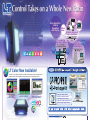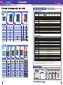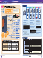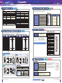
1
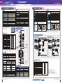
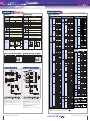
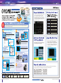
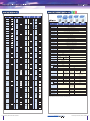
All-in-One unit for
Control,
Operation
Which
means...
and Display
Graphical display and
Touch Operation!
Pro-face's
combined HMI
and control
software is easy
to use.
Less wiring
and less space!
Frees up
space around
the control
panel !
NEW
Simple
wiring means
easier
maintenance
too.
Screen Editor and
Logic Program Development
Software
LT Color Now Available!
The new LT color display is easier to see than monochrome monitors, making it easier
to monitor status in the workplace and improving control of the production floor.
Improves visibility by
color-coding
graphics and text.
Makes warnings and alarms
easier to understand.
Enables instant device
status Verification with
BMP image display
5.7
inch
Software
advantages!
Easy Screen
Creation
Easy Logic
Programming
Supports Ladder Monitor
Variety of Ladder Instructions
Expanded Alarm Summary
Improved Keypad Display Function
Various graphic types Available
* Built-To-Order product. Please contact
your local Pro-face distributor.
ADP only *
Data created with LT Editor can also be used.
See our Web site for LT Series system application examples.
LT Series System Design
02
Our complete lineup matches your needs
5.7
inch
Functional Specifications
64Colors STN LCD
Item
Sink
Sink
output
Sink
output
output
ADP
16
16
16
16
16
16
16
16
Analog Input (ch)
*1
2
2
2
Analog Output (ch)
*1
1
2
2
High-speed Counter
*1
4*2
4*2
4*2
Pulse Output
*1
4*3
4*3
4*3
Thermocouple(J/K)
Temperature Input
Blue / White
CFL (lifespan: more than 25,000 hours when continuously lit)
Electrical
Remote I/O (Flex Network)
*1 Compatible with Flex Network units.
*2 Shared with DC24V input.
*3 Shared with DC24V output.
BLUE Monochrome LCD
Sink
Item
output
Type A
output
Type B+
Type B
Type C
Source
output
Type H
AD
ADT
ADP
Structural
output
Sink
Environmental
output
Source
DC24V Input Points
DC24V Output Points
Analog Input (ch)
8 levels via touch panel
Language Fonts
ASCII: (Code Page 850) Alphanumeric (including European fonts), Chinese: (GB2321-80 codes) simplified Chinese fonts,
Japanese: ANK 158 type, Kanji; 6962 types (includes non-kanji: 607, and Standard JIS Type 1 and 2),
Korean: (KSC5601-1992 codes) Hangul fonts, Taiwanese: (Big 5 codes) traditional Chinese fonts
Display Sizes*1
8 x 8, 8 x 16, 16 x 16, 32 x 32 dots
Font Sizes
Both height and width can be expanded 1, 2, 4, or 8 times
8 x 8 Dots
40 char. x 30 rows
8 x 16 Dots
40 char. x 15 rows
16 x 16 Dots
20 char. x 15 rows
32 x 32 Dots
10 char. x 7 rows
Application
1MB FLASH EPROM (approx. 320 screens at 3.2KB/screen)
Data Backup
96KB SRAM (uses lithium battery*2)
Variable Data Area
32KB SRAM (uses lithium battery*2)
Program Area
128KB FLASH EPROM
Touch Panel
16 x 12 keys/screen (1 or 2 point touch)
Clock Accuracy
±65 seconds/month (at room temperature)
General Specifications
2
Sink
Contrast Control
Item
Pt100 Temperature Input
W115.2mm[4.54in] x H86.4mm[3.40in]
*1 The font used varies depending on the language and font size selected.
*2 A lithium battery's lifetime is 10 years when the battery's ambient temperature is under 40 degrees centigrade, 4.1 years when the battery's ambient temperature is under 50 degrees centigrade, and 1.5 years when the battery's
ambient temperature is under 60 degrees centigrade. When used for backup, the lifetime is approximately 60 days with a fully charged battery, and approximately 6 days with a half-charged battery.
3
5.7
inch
monochrome LCD
CFL (lifespan: more than 36,000 hours when continuously lit)
Text
ADT
Type H
320 x 240 pixels
Backlight
Displayable
Characters
16
Type H
AD
DC24V Output Points
STN Color LCD
64 colors
Control
Memory Memory
16
Display Type
Type C
A1 (Sink Output Type)
H1 (Sink Output Type)
GLC150-BG41-XY32SK-24V
GLC150-BG41-AD*K-24V
GLC150-BG41-XY32KF-24V GLC150-BG41-FLEX-24V GLC150-BG41-RSFL-24V H2 (Source Output Type)
A2 (Source Output Type)
GLC150-BG41-AD*C-24V
GLC150-BG41-XY32SC-24V
W118.2mm[4.65in] x H89.4mm[3.52in]
*Built-To-Order product. Please
contact your local Pro-face distributor.
DC24V Input Points
Model
H1 (Sink Output Type)
GLC150-SC41-AD*K-24V
A1 (Sink Output Type)
GLC150-SC41-XY32KF-24V
GLC150-SC41-XY32SK-24V
H2 (Source Output Type)
GLC150-SC41-ADPC-24V
Color, Gradation
output
Type B+
Blue(Monochrome)Type
Type B+
Type B
Type A
Nominal Display Area
Source
Type A
Type H
Resolution
ADP only*
Item
ColorType
Type B+
Type A
Type A
Color Type
Type B+
Type H
Type A
Type B+
Input Voltage
DC24V
Rated Voltage
DC20.4V to DC28.8V
Allowable Voltage Drop
10 ms or less
Power Consumption
20W or less
Blue(Monochrome)Type
Type B
Type C
In-Rush Current
30A or less
Voltage Endurance
AC1000V at 10mA for 1 minute (between charging and FG terminals)
Insulation Resistance
Above 20MΩ at DC500V (between charging and FG terminals)
Operating Temperature
(Panel Interior and Panel Face)*1
0°C to 50°C
Storage Temperature
-20°C to +60°C
Operating Humidity
10% RH to 90% RH (no condensation,wet bulb temperature: 39 C or less)
Storage Humidity
10% RH to 90% RH (no condensation,wet bulb temperature: 39 C or less)
Air Purity (Dust)
0.1mg/m3 or less (non-conductive levels)
Type H
o
o
Corrosive Gases
Free of corrosive gases
Atmospheric Endurance
(Operation Altitude)
800hPa to 1,114hPa (2,000 meters or lower)
Vibration Resistance
IEC61131-2 (JIS B 3502) compliant
When vibration is NOT continuous: 10Hz to 57Hz 0.075mm, 57Hz to 150Hz 9.8m/s2
When vibration is continuous: 10Hz to 57Hz 0.035mm, 57Hz to 150Hz 4.9m/s2
X, Y, Z directions for 10 times (80min)
Noise Immunity
(via noise simulator)
Noise voltage: 1500Vp-p*2, Pulse Duration: 1µs, Arise time: 1ns
Electrostatic Discharge Immunity
Contact discharge of 6kV (IEC 61000-4-2 Level 3)
Certifications
CE Marking (EN55011 class A, EN61000-6-2), UL / C-UL (UL 508, UL1604)
Grounding
100Ω or less, or your country's applicable standard
Rating*3
Equivalent to IP65f (JEM 1030), and NEMA#250 TYPE4X/12
External Dimensions
W207mm[8.15in]
H157mm[6.18in]
Weight
1.5kg (3.3lb) or less
Cooling Method
Natural air circulation
D75.8mm[2.98in]
*1 Ensure that the temperatures both at the display surface and inside the panel are within the prescribed ambient temperature range during use. Use at temperatures outside this range may lead to malfunction.
*2 1000 Vp-p for pulse output and PWM output functions.
*3 Limited to the front face after installation in a panel. Testing equivalent to IP65f conditions has been performed; however, performance cannot be guaranteed for every type of environment.
If the product is subjected to an oil mist over an extended period of time, even when using the oil designated in the tests, or if the product is subjected to an extremely low-viscosity cutting oil, some oil penetration may result due to
peeling of the front sheet. If this occurs, a countermeasure is required. Similar penetration, or plastic deformation, may also occur with oils other than those designated. Confirm operation environment prior to installation.
Furthermore, rubber gaskets that have been used for extended periods of time, and those that have been scratched or soiled after installation, may not provide sufficient protection.
It is recommended that the rubber gasket be replaced periodically to guarantee consistent protection.
Analog Output (ch)
High-speed Counter
03 LT Series Line-up & Specifications
75.8 [2.98]
6 [0.24]
75.8 [2.98]
6 [0.24]
75.8 [2.98]
75.8 [2.98]
6 [0.24]
6 [0.24]
6 [0.24]
141.2 [5.56]
Under 4-R3
75.8 [2.98]
141.2 [5.56]
141.5
Side View
[7.54 +0.04
]
0
+1
0
157 [6.18]
SIO
*1 Compatible with Flex Network units.
*2 Shared with DC24V input.
*3 Shared with DC24V output.
+1
0
[5.57 +0.04
]
0
191.5
Pt100 Temperature Input
Remote I/O (Flex Network)
Panel Cut
141.2 [5.56]
Thermocouple(J/K)
Temperature Input
Unit: mm [in.]
141.2 [5.56]
191.2 [7.53]
141.2 [5.56]
Pulse Output
207 [8.15]
See our Web site for LT Series system application examples.
LT Series Line-up & Specifications
04
Reduces wiring and expands system scalability
Integrates easily into compact equipment
5.7
inch
5.7
inch
16 input points and 16 output points make for easy integration
into your current system
5.7
inch
Built-in DIO (Sink output) Type
Tool Connector
Use Flex Network to connect up to 1008 points (63 nodes) over a
maximum of 400m (with 6Mbps, 200m x 2 ch).
5.7
inch
Built-in DIO (Source output) Type
Built-in Remote I/O (Flex Network)
Data Transfer Cable
Tool Connecctor
( COM ) GPW-CB02
( USB ) GPW-CB03 *1
( COM ) GPW-CB02
( USB ) GPW-CB03 *1
*1 Limited by software version
*1 Limited by software version
Bar Code Reader
Conversion Cable
DIO I/F
Indicator Lamp
Sensor
Connectors
Serial Printer
(provided by user)
Only when using
GPW-CB02
Equipped
with DC24V
32-point
input/output
Bar Code Reader
Only when using
GPW-CB02
200m (6Mbps)x 2ch
100m (12Mbps) x 2ch
Use the LT's
built-in Remote
I/O (Flex Network)
together with
etc.
PLC
with 50 I/O points
I/O points used for panel
operation and display
12 input points *1
9 output points *2
I/O points used for
equipment control
29 points available
LT Series (Type A/B+)
with 32 I/O points
Built-in graphic display and touch panel
replace switches and lamps.
32 points available
All avilable
for device
control!
5.7
inch
Printer
*1 Used for switches, such as manual/auto (2
points), auto start, stop, stop, buzzer, alarm
reset , jog forward, jog backward, raise, lower,
continuous operation, and material
replenishment complete.
*2 Used for lamps indicating auto operation,
motor overload, error, lower error, stop error,
pneumatic error, material jam, and no material.
Maximum 1008 I/O Points
Flex Network Communication Cable
10m: FN-CABLE2010-31-MS
50m: FN-CABLE2050-31-MS
200m: FN-CABLE2200-31-MS
Remote I/O ( Flex Network )
System
• Single-axis Positioning Unit
• High-speed Counter Unit
• Analog Units
• DIO Units
Things to remember when comparing I/O points!
Serial Printer
(provided by user)
Flex Network I/F
LED
Switch
Conversion Cable
Printer
Extend your system with two types of built-in I/O
5.7
inch
Data Transfer Cable
Connect to temperature controllers, inverters,
PCs and single-board controllers
5.7
inch
Further expansion with the SIO I/F, in addition to the Remote I/O (Flex
Network)
Built-in SIO + Remote I/O (Flex Network)
Further expand your Remote I/O (Flex Network) system with built-in
32-point DIO
Built-in Remote I/O (Flex Network)
Tool Connector
Data Transfer Cable
( COM ) GPW-CB02
( USB ) GPW-CB03 *1
*1 Limited by software version
Tool Connector
Data Transfer Cable
( COM ) GPW-CB02
( USB ) GPW-CB03 *1
Bar Code Reader
*1 Limited by software version
Conversion Cable
Only when using
GPW-CB02
Bar Code Reader
Conversion Cable
Only when using
GPW-CB02
DIO I/F
Connectors
Use the LT's
built-in Remote
I/O (Flex Network)
together with
• Single-axis Positioning Unit
• High-speed Counter Unit
• Analog Units
• DIO Units
05 LT Series System Design
Indicator Lamp
LED
Sensor
Switch
Equipped
with DC24V
32-point
input/output
Flex Network Communication Cable
10m: FN-CABLE2010-31-MS
50m: FN-CABLE2050-31-MS
200m: FN-CABLE2200-31-MS
200m (6Mbps)x 2ch
100m (12Mbps) x 2ch
Printer
Maximum 1008 I/O Points
Flex Network Communication Cable
10m: FN-CABLE2010-31-MS
50m: FN-CABLE2050-31-MS
200m: FN-CABLE2200-31-MS
Remote I/O ( Flex Network )
System
Serial I/F
RS-232C/RS-422 Cable
etc.
Flex Network I/F
200m (6Mbps)x 2ch
100m (12Mbps) x 2ch
Printer
Flex Network I/F
Serial Printer
(provided by user)
(provided by user)
Maximum 1008 I/O Points
Remote I/O ( Flex Network )
System
External controllers
Use the LT's
built-in Remote
I/O (Flex Network)
together with
• Single-axis Positioning Unit
• High-speed Counter Unit
• Analog Units
• DIO Units
Standard serial
interface allows you
to easily connect a PC,
single-board controller,
temperature controller,
inverter or other device
via an RS-232C or RS422 cable.
See our Web site for LT Series system application examples.
PC
Inverter
Temperature
controller
Microcomputer
board
LT Series System Design
06
Comes equipped with analog I/O,
temperature input and pulse output
5.7
inch
5.7
inch
5.7
inch
Easily...
• Control pressure and flow
• Set positioning
• Monitor temperature, etc.
ADP only *
5.7
inch
: Sink Type
Built-in 32-point DIO + 2-point AD/1-point DA
Built-in 32-point DIO + 2-point AD/2-point DA
+3-point Thermocouple Input
Built-in 32-point DIO + 2-point AD/2-point DA
+2-point Pt100 Input
: Source Type
* Built-To-Order product.
Please contact your local Pro-face distributor.
Tool Connector
Data Transfer Cable
( COM ) GPW-CB02
( USB ) GPW-CB03 *1
*1 Limited by software version
Bar Code Reader
Serial Printer
Conversion Cable
Only when using
GPW-CB02
(provided by user)
Printer
DC
Push Button
Input
DIO I/F
High-Speed
Counter
KIV Cable
Sensor
etc.
Graphic Display Screen
I/O LED (Type A1/A2/B+/H1/H2)
Displays application screens and host data.
Indicates the input/output status of DIN/DOUT.
Tool Connector
Touch Panel
Switches screens, inputs values, provides switch
and lamp functions, and writes data to host equipment.
Integrated Wattmeter
Flow Meter
Rotary
Encoder
(provided by user)
Heater
Lamp
Valve
Temperature Input I/F
Output
PWM
Magnet Switch
Motor Driver
etc.
Inverter
LED
Controller mode*1
––
Green – Lit
RUN
Green – Lit
STOP
Green – Blinking
Backlight Malfunction Detected Green/Red – Lit
Major Error (STOP)
Red – Lit
Thermocouple
( J Type / K Type Input)
Equipped
with DC24V
32-point
input/output
Temperature
input
Executes logic program operation
In RUN mode, RUN/STOP of logic program can be
controlled by Editor or Offline.
STOP: Stops logic program operation
Stops the logic program regardless of the software setting.
Alarm Output
Input
[ LT Type H-AD Input (2ch) Output (1ch) ]
Analog Input/Output Connector (Type H1/2)
Connects control units such as sensors, using a
screw-clamp type connector.
ERR (Red)
Description
Lit during normal operation.
Lit when communication
with a connected unit is blocked.
DIO Input/Output Connector (Type H1/2)
Connects external Input/Output units, using a
spring-clamp type connector.
Temperature Input Interface (Type H1/2)
Serial I/F (Type C )
Connects a temperature controller, inverter or other
external device, via an RS-232C or RS-422 cable.
Connects Pt100 or thermocouple sensors using a
screw-clamp type connector.
* ADT/ADP Type only.
Turns the contact OFF (open) when a major error or watchdog timer
error is generated. See page 10, External Interfaces (Alarm Output).
Load Cell
Output
[ LT Type H-ADT/ADP Input (2ch) Output (2ch) ]
Status LED
RUN/STOP Switch (LED is lit in RUN mode)
Platinum Temperature Resistor
LED
OFF
ON
Indicates the status of Flex Network data communication.
RUN:
Pt100 Input
Analog
input/output
Connects I/O units, analog units, or other Flex Network
units via Flex Network communication cables.
RUN (Green)
Thermocouple
Status
I/O board error
I/O board is normal
Remote I/O (Flex Network)
System Connector (Type B+/ B/C)
Flex Network Status LED (Type B+/ B/C)
Connects power and FG terminals.
Motor Driver
Indicates the LT unit's current status.
*1 Indicates the logic program status. *2 Indicates the display and touch key status.
Power Supply Terminal Block
Pulse Line
Ready LED (Type H1/2)
* The Flex Network S-No. (node address) occupies one node
in the Type B+DIO connector.
Operation mode*2
Offline
Online
Online
Online
Online
Analog Meter
Analog I/F
Rotary Switch (Type B+)
Used to set the S-No.'s right-most hex digit.
Connects external input or output equipment.
Indicates the LT unit's operation status.
Transistor
Connects to a data transfer cable.
DIO Connector (Type A1/A2/B+)
Status LED
etc.
Dip Switches (Type B+)
These switches control the DIO connector's
Output Hold. Also, they are used to set
the S-No.'s left-most hex digit.
Position Change Sensor
Recording Meter
Heater
Control Valve
Product Name
Software
Choose from 3 types to better match your needs!
Function
Type H-AD
Main Unit
Options
Type H-ADT
Type H-ADP
DC24V 16 Input Points
(10kpps 16-bit high speed counter x 4 points possible. *1)
Maintenance
Options
DC24V 16 Output Points
(5kpps pulse line output or 2.5kHz PWM x 4 points possible. *2)
Analog Input
(12-bit resolution, no insulation between channels)
Analog Output
(12-bit resolution, no insulation between channels)
Thermocouple Temperature Input (J/K)
(no insulation between channels)
( 2ch )
( 2ch )
( 2ch )
( 1ch )
( 2ch )
( 2ch )
( 3ch )
Pt100 Temperature Input
(no insulation between channels)
Peripheral
Unit Options
( 2ch )
GP-PRO/PB C-Package 03
Screen Protection Sheet (Hard Type)
DIO Connector & Cover (Soldered Type)
DIO Connector (Pressure Type)
Installation Fasteners
Installation Gasket
Flex Network I/F Connectors
DIO Connectors for LT Type H
Analog I/O Connectors for LT Type H
Temperature Input Connectors for LT Type H
RS-232C Cable
RS-422 Cable
Description
LT Series development software
Protects display surface and keeps unit clean (5 sheets/set)
GP37W2-DF00
GLC100-DIOCN01
GLC-DIOCN02
GP070-AT01
GP37W2-WP00-MS
FN-IFCN01
GLC-DIOCN04
GLC-AIOCN01
GLC-TMCN01
GP410-IS00-O
GP230-IS11-O
Single-axis Teaching Loader
FN-PC10LD41
Multi-Link Cable
RS-422 Connector Terminal Block Conversion Adapter
Data Transfer Cable
USB Data Transfer Cable
GP230-IS12-O
DIO Cables
I/O Connector Terminal Block for FN-XY32SKS41
*1 Each point with matching hardware output is 10kpps single phase 4 ch or dual phase 1 ch + single phase 2 ch.
*2 Pulse line output is 4 points, with 4-point total 5kpps maximum, PWM 2.5kHz for each point, combined use of high-speed counter matching output. DC24V output capacity.
(Output 0.5A x 8 points (1 common) / 0.2A x 8 points (1 common))
Model
GPPRO-CNT01W-P03
(10m)
Flex Network Communication Cables (50m)
(200m)
Single-axis Motor Driver Connection Cable (1m)
Single-axis Teaching Loader Cable (5m)
GP070-CN10-O
GPW-CB02
GPW-CB03
CGP070-ID11-M
GLC000-DIOCB11-MS
GLC-DIOCN03
FN-CABLE 2010-31-MS
FN-CABLE 2050-31-MS
FN-CABLE 2200-31-MS
FN-PC10CB01
FN-LD10CBL
Type A1/A2/B+ DIO Connector (5 sets of connectors and covers)
Type A1/A2/B+ DIO Connector (5 sets of connectors)
For attaching LT Series unit to a solid panel. (set of 4)
For attaching LT Series unit to a solid panel.
Type B+/B/C Flex Network Connectors (set of 5)
Attaches LT to DIO I/F (set of 2)
Attaches LT to Analog I/F (set of 5)
Attaches LT to Temperature I/F (set of 5)
Interface cables for data transmission between host controllers and LT Series.
Interface cables for data transmission between host controllers and LT Series.
Program-input unit for the Flex Network Single-axis positioning unit. Used for parameter entry,
as well as positioning check and movement. (Also includes one FN-LD10CBL.)
RS-422 interface cable for multiple-type (n:1) data transmission between host controllers and LT Series units.
Converts SIO to RS-422 terminal block.
Connect LT Series to a PC for downloading GP-PRO/PB
Connect LT Series to a PC for downloading GP-PRO/PB
C-Package data
C-Package data
Open-end Sink DIO cable, 3m (Type A1/A2/B+)
Open-end Sink/Source DIO cable, 3m (Type A1/A2/B+)
Flex Network 64-point DIO connector terminal blocks, Spring-clamp type (set of 2)
Connects distributed Flex Network units (Type B+/B/C)
Connects the Flex Network Single-axis positioning unit and the servo and stepping drivers.
Connects Single-axis Positioning unit to Single-axis Teaching Loader.
* Manual: Download the necessary PDF manuals from our web site (http://www.pro-face.com), or contact your local Pro-face distributor.
07 LT Series System Design and Options
See our Web site for LT Series system application examples.
LT Series System Design and Options
08
Input
This I/F unit's high-speed remote I/O (6Mbps/12Mbps) is so fast, you won't think you are using a remote connection.
Up to 1008 I/O points can be connected, with a communication delay of only 0.94ms (for 512 points at 12Mbps).
The network can be extended up to 400 meters (2 channels at 6Mbps).
Output
Type A1/A2
Rated Voltage
Max. Allowable Voltage
Input Type
Rated Current
Input Resistance
Standard
Operating Range
Type B+
Type A1/A2
Rated Voltage
Rated Voltage Range
DC24V
DC26.4V
Source/Sink input
5mA (24V)
4.7kΩ
ON voltage: 21V or more.,
OFF voltage: 7V or less.
OFF
ON: 10ms or less.,
ON
OFF: 10ms or less.
Input Delay
Output Type
5.7mA (24V)
4.2kΩ
ON voltage: 15V or more.,
OFF voltage: 5V or less.
OFF
ON: 1.5ms or less.,
ON
OFF: 1.5ms or less.
Max. Load Current
Output Voltage Drop
Output Delay
Leakage Current when OFF
Output Classification
Common
Common Structure
External Connection
Output Protection Classification
Internal Fuse
Surge Suppression Circuit
Output Points
Output Signal Indication
Isolation Method
External Power Supply
1
16 points / 1 common line
40-pin connector(also used for output)
16
LED lights for each point ON (logical side)
Photocoupler isolation
For Signal: DC24V
Common
Common Structure
External Connection
Input Points
Input Signal Indication
Isolation Method
External Power Supply
Type B+
DC24V
DC24V±10%
Type A1: Sink output
Sink output
Type A2: Source output
0.2A/point, 1.6A/common
2.5V or less
1.5V or less
OFF
ON: 2ms or less.,
OFF
ON: 1ms or less.,
ON
OFF: 2ms or less.
ON
OFF: 1ms or less.
0.4mA or less
0.1mA or less
Transistor output
1
16 points/ 1 common line
40-pin connector (also used for input)
No protection
3.5A,125V chip fuse (not replaceable)
Diode
16
LED lights for each point ON (logical side)
Photocoupler isolation
DC24V
I/F Connector
Communication Configuration
1: N
Connection Method
Multi-Drop Connection
Pin
Signal
Pin
Signal
A1
A2
A3
A4
A5
A6
A7
A8
A9
A10
A11
A12
A13
A14
A15
A16
A17
A18
A19
A20
COM (0V:DOUT)
COM (0V:DOUT)
NC
NC
DOUT15
DOUT14
DOUT13
DOUT12
DOUT11
DOUT10
DOUT9
DOUT8
DOUT7
DOUT6
DOUT5
DOUT4
DOUT3
DOUT2
DOUT1
DOUT0
B1
B2
B3
B4
B5
B6
B7
B8
B9
B10
B11
B12
B13
B14
B15
B16
B17
B18
B19
B20
COM (24V:DIN)
DC24V (DOUT)
NC
NC
DIN15
DIN14
DIN13
DIN12
DIN11
DIN10
DIN9
DIN8
DIN7
DIN6
DIN5
DIN4
DIN3
DIN2
DIN1
DIN0
A1
B1
B20
A20
* This front diagram shows the connector on the DIO unit side.
When preparing the cable, note that the A and B characters indicate the number 1 pins.
Input Circuit
Internal
Circuit
5
5
Channel 2 communication data
TR-
4
Channel 2 communication data
TR+
3
Channel 1 shield line
SLD
2
Channel 1 communication data
TR-
1
Channel 1 communication data
TR+
3
Communication I/F
Differential Method, pulse transfer resistance
2
Error Check
Format, bit, or CRC-12 verification
Max. Number of Nodes
63 (max.), 1008 I/O points
(depending on type of units used.)
Asynchronous: RS-232C/RS-422;
data length: 7 or 8 bits;
stop bit: 1 or 2 bits; parity: none,
Transmission rate: 2400bps to 115.2Kbps
Front View*
Signal
COM(0V:DIN)
0V(DOUT)
NC
NC
DIN15
DIN14
DIN13
DIN12
DIN11
DIN10
DIN9
DIN8
DIN7
DIN6
DIN5
DIN4
DIN3
DIN2
DIN1
DIN0
A1
B1
Recommended Connector: Dsub 25-pin plug XM2A-2501 (Omron)
Recommended Cover:
Dsub 25-pin cover XM2S-2511 (Omron)
Jack Screw
XM2Z-0071 (Omron)
* Use M2.6 x 0.45 coarse thread screws to mount.
Recommended Cable:
CO-MA-VV-SB5P 28AWG (Hitachi Cable,ltd)
Refer to the GP-PRO/PB External Device Connection Manual (included with the
GP-PRO/PB C-Package) for external controller connection information, or visit our website.
B20
A20
4
1
Pin
Code
1
FG
Front View
Signal Name
Frame Ground
2
SD
Send Data (RS-232C)
3
RD
Receive Data (RS-232C)
4
RS
Request Send (RS-232C)
5
CS
Clear Send (RS-232C)
6
NC
No Connection
7
SG
Signal Ground
8
CD
Carrier Detect (RS-232C)
9
TRMX
Termination (RS-422)
10
RDA
Receive Data A (RS-422)
11
SDA
Send Data A (RS-422)
12*
RESERVE
Reserved
13*
RESERVE
Reserved
14
VCC
5V ±5% Dutput 0.25A
15
SDB
Send Data B (RS-422)
16
RDB
Receive Data B (RS-422)
17
NC
No Connection
18
CSB
Clear Send B (RS-422)
19
ERB
Enable Receive B (RS-422)
20
ER
Enable Receive (RS-232C)
21
CSA
Clear Send A (RS-422)
22
ERA
Enable Receive A (RS-422)
23
NC
No Connection
24
NC
No Connection
25
NC
No Connection
1
14
25
13
*Pins 12 and 13 are reserved and are not available for connection.
Output Circuit
Internal Circuit
B20
Internal
Circuit
Input Circuit
DC 24V External
Power Supply
COM B1
DC 24V
External
Power Supply
Output Circuit
Internal Circuit
Internal Circuit
+ -
Internal
Circuit
B2
0V
A5
OUT
A20
OUT
Internal Circuit
IN
B5
IN
B20
-+
A2
3.5A
COM B1
- +
OUT
A1 COM
* Dotted line shows the source output device connection.
IN
*
OUT
B5
Quick Break Fuse
-+
+ -
Internal Circuit
A20
*
SLD
I/O Connector Specifications
Input Circuit
B2 +24V
A5
IN
Channel 2 shield line
DC 24V External
Power Supply
COM B1
IN
B1
B2
B3
B4
B5
B6
B7
B8
B9
B10
B11
B12
B13
B14
B15
B16
B17
B18
B19
B20
Output Circuit
+ -
*
Pin
COM(24V:DOUT)
COM(24V:DOUT)
NC
NC
DOUT15
DOUT14
DOUT13
DOUT12
DOUT11
DOUT10
DOUT9
DOUT8
DOUT7
DOUT6
DOUT5
DOUT4
DOUT3
DOUT2
DOUT1
DOUT0
6
6Mbps/12Mbps (selectable)
* This front diagram shows the connector on the DIO unit side.
When preparing the cable, note that the A and B characters indicate the number 1 pins.
DC 24V External
Power Supply
-+
Signal
A1
A2
A3
A4
A5
A6
A7
A8
A9
A10
A11
A12
A13
A14
A15
A16
A17
A18
A19
A20
6
Communication Speed
I/O Connectors (Type A2: Source Output )
Pin
Signal Name
Communication Method
Serial I/F
Front View*
Condition
200m/channel at 6Mbps,
100m/channel at 12Mbps
During cyclic period, distributed transmission.
Half-duplex
Max. Distance
The sink/source type DIO integrates 16 input/output points into a compact unit.
The Type A1/A2/B+ LT supports up to 16-point inputs and 16-point outputs, ideal for connecting peripheral I/O devices.
I/O Connectors (Type A1/B+: Sink Output )
Pin No.
B2
+24V
A5
OUT
A1
Internal Circuit
Internal
Circuit
3.5A
COM + -
Quick Break Fuse
* Dotted line shows the sink output device connection.
DC 24V External
Power Supply
DIO Connector
Connection Method
Model Name
Solder-type*
GLC100-DIOCN01
*Set includes FCN-361J040-AU (connector) and FCN-360C040-B (cover)
B5
Manufacturer
Type
A20
OUT
Internal
Circuit
A2
IN A20
Internal Circuit
* Dotted line shows the source output device connection.
09 LT Series Built-in Interface Specifications
3.5A
COM
-+
DC 24V
Quick Break Fuse External
Power Supply
Fujitsu Takamizawa
Components
FCN-361J040-AU
FCN-360C040-B
(Connector)
(Cover)
Crimp type
FCN-363J040
FCN-363J-AU/S
FCN-360C040-B
(Connector)
(Contact)
(Cover)
Press-fit type
Contact Rating
AC125V at 0.15A (resistive load),
DC24V at 0.6A (resistive load)
Set Time (at 20˚C)
4ms or less
Reset Time (at 20˚C)
4ms or less
Min. Switching Load
1mA/DC5V
Initial Contact Resistance
100mΩ or less
When the LT unit’s power is turned ON, the Alarm Output is
turned OFF for approximately 1 second. Be sure to design
your circuits to disregard a 1 second Alarm Output stop
after the LT unit’s power is turned ON.
ALARM
Note: This relay switch is OFF from the time the power is turned on
until the LT Series system is booted. The external monitoring
circuit must be started after the LT Series system is booted.
Connector
Solder type
A1
Alarm Output
A2
FCN-367J040-AU/F (Connector)
Tool Connector
Tool Connector
Asynchronous: TTL level non-procedural command I/O
During Screen File Deveropment : Connect data transfer cable
for transferring data from GP-PRO/PB C-Package.
During Operation : Connect a variety of devices including a bar-code reader.
See our Web site for LT Series system application examples.
LT Series Built-in Interface Specifications
10
Input Derating
*1
Operation
Range
ON Voltage: DC19V or more
OFF Voltage: DC5V or less
Input Delay
Time
Common Lines
Common Line Allocation
Input Points
OFF to ON: 0.5 to 20ms or less*2
ON to OFF: 0.5 to 20ms or less*2
2
8 points/1 common line
16
Input Signal Display
LED lights when each point turns ON
(logical side)
Isolation Method
Polarity
ExternalPower Supply
Photocoupler Isolation
None
For Signal: DC 24V
*1 Exceeding the LT unit’s input rated voltage may affect the input
ON voltage, input points, or ambient operating temperature;
the unit’s input terminals may be damaged due to excessive
heat.Use Input Derating within the range shown in the chart
below, to prevent unit malfunction.
*2 Digital filter can be set at intervals of 0.5ms.
A1
A2
A3
A4
A5
A6
A7
A8
A9
A10
A11
A12
A13
A14
A15
A16
A17
A18
Signal Name
B1
B2
B3
B4
B5
B6
B7
B8
B9
B10
B11
B12
B13
B14
B15
B16
B17
B18
OUT14
OUT13
OUT12
OUT11
OUT10
OUT9
OUT8
COM3
OUT7
OUT6
OUT5
OUT4
OUT3 (PLS3, PWM3)
OUT2 (PLS2, PWM2)
OUT1 (PLS1, PWM1)
OUT0 (PLS0, PWM0)
COM2
Input ON Rate
No. of Input Channels
At Voltage Setup
Input Range
At Current Setup
At Voltage Setup
Resolution
At Current Setup
Brightness
Linearity
At Voltage Setup
Input
Impedance At Current Setup
Input Delay Time
Absolute Max. Input Voltage
Input Filter
Power Supply
2 Channels
0V to 10V (10.2375V max.) *1
0mA to 20mA (20.475mA max.) *1
12 Bit (0-4000 (0V to 10V),4095 max. (at 10.2375V))
Type H1 Sink Output
Type H2 Source Output
0.2 A/point
0.8 A/common
2 A/common
0.5V or less
OFF to ON: 0.5 ms or less, ON to OFF: 0.5 ms or less
Output Points
Output Protection Type
16 (8 points/1 common line)
0.1 mA or less
Transistor Output
1 each
8 points/1 common line
Internal Fuse
Surge Control Circuit
Output Signal Display
Isolation Method
2A Chip Fuse (non-replaceable)
DC 28.8V
50
Move average sampling time 2ms
DC24V External Power Supply
Insulation
Input Current
4095
Input
Characteristics
Output
Characteristics
4095
4000
10V 10.2375V
0
Sink IN and Source IN/Sink OUT
Analog Input
Extemal Power
Supply DC24V
Output
Range
0mA to 20mA (20.475mA max.) *1
12 Bit (0 to 4000 (0V to 10V), 4095 max. (at 10.2375V))
12 Bit (0 to 4000 (0mA to 20mA), 4095 max. (at 20.475mA))
±1.0% of full scale (0°C to 50°C)
10kΩ or more
500Ω or less
DC24V External Power Supply
Each channel - Internal: Insulated
Between each channel: Non-insulated
Each Analog Power channel: Insulated
Output Voltage
Photocoupler Isolation
4000
Output Current
10.2375V
20.475mA
10V
20mA
4000 4095
0
Digital Input
0
4000 4095
Digital Input
20mA 20.475mA
0
Analog Input
*1 Switching the Voltage Input or Current Input can be set separately, in each channel.
*1 Switching the Voltage Input or Current Input can be set separately, in each channel.
Important:
• Use twisted-pair, shielded coaxial cable for analog input line(s) and be sure these lines are placed
in a separate duct from high-frequency, live lines such as high-voltage, high-power lines, inverters, etc.
Internal Circuit
Pin Assignments
Internal Circuit
B1
A1
Scan time + (2ms Input Channels)
DC15V (Voltage)/ 60mA (Current)
Input Voltage
LED lights when each point turns ON (logical side)
For signal: DC 24V
AD: 1 Channel
ADP: 2 Channels
ADT: 2 Channels
0V to 10V (10.2375V max.) *1
Each channel - Internal: Insulated
Between each channel: No Insulated
Each channel - Analog Power: Insulated
Zener Diode (DC39V±1V)
External Power Supply
Specifications
No. of Output Channels
At Voltage Setup
At Current Setup
At Voltage Setup
Resolution
At Current Setup
Br ightness
At Voltage Setup
External
Allowable Load At Current Setup
Power Supply
100 kΩ
250Ω
Insulation
5A Chip Fuse (non-replaceable)
Item
12 Bit (0-4000 (0mA to 20mA),4095 max. (at 20.475mA))
±1.0% of full scale (0°C to 50°C)
±3 LSB max.
Output is unprotected
IN15
IN14
0.5 A/point
Output Delay Time
Current Leakage (when OFF)
Type of Output
Common Lines
Common Design
0
30
40
10
0
20
50 (°C)
Ambient Operating Temperature
Pin No. Signal Name
OUT15
DC 24V
DC 24.0V to DC 26.4V
(%)
100
DIO Connector
Pin No.
Specifications
DC 20.4V to DC 28.8V
Maximum Load Current
Output Voltage Drop
Approx. 2.7kΩ (IN0, IN2, IN4, IN6)
Approx. 4.7kΩ (Other input)
Input Impedance
Item
Output Method
9 mA (DC24V) (IN0, IN2, IN4, IN6)
5 mA (DC24V) (Other input)
Output
LC (Low Current) OUT0 to OUT7 HC (High Current) OUT8 to OUT15
Analog Output
DC 24V
DC 28.8V
Source/Sink input
Rated Current
Input
Item
Rated Voltage
Rated Voltage Range
Digital Output
Specification
Analog Output
Output
Item
Rated Voltage
Max. Allowable Voltage
Input Method
Digital Output
Input
IN13
Analog Input Circuit
Internal Circuit
IN12
IN11
Analog output Circuit
When setting Current Input
Internal Circuit
When setting Current Output
IN10
IN9
Internal Circuit
IN8
COM1
*1
Internal Circuit
IN7
Extemal Power
Supply DC24V
IN6 (CT3)
Internal Circuit
IN5
IN4 (CT2)
Internal Circuit
IN3
Extemal Power
Supply DC24V
IN2 (CT1)
IN1
*1 Ground this wire when noise
or other problems occur
during unit operation.
*2 The dotted line circuit is used
for the Source IN circuit.
When setting Voltage Input
When setting Voltage Output
Sink IN and Source IN/Source OUT
IN0 (CT0)
B18
A18
COM0
Extemal Power
Supply DC24V
Using GP-PRO/PB C-Package 03, you can set the standard DIO for use as high-speed counter input.
Refer to the Manual.
• Parenthesized signal names ( ) indicate when Pulse output (PLS*), PWM output (PWM*), or Counter Input (CT*) are used.
B2L3.5/36LH 36 pole spring-clamp connector (Weidmuller) Wire size: 0.3mm to 1.0mm (AWG#18 to AWG#22)
• The terminals for DIO power supply are located on the analog input/output connector.
About COM
*3
Internal Circuit
Pin No.
Signal Name
B18
B9
COM0
COM1
A18
COM2
A9
COM3
*2
*2
Internal Circuit
*3
Function
Input Common (For IN0 to IN7) (For CT0 to CT3)
Input Common (For IN8 to IN15)
Output Common (For OUT0 to OUT7)
(For PLS0 to PLS3, PWM0 to PWM3)
Output Common (For OUT8 to OUT15)
Internal Circuit
Pin No.
Pin No.
Internal Circuit
*1 When the Current Input is selected, ground Al* and Al* JP. *2 Connect to the FG terminal in the main unit, or connect directly to frame ground (FG).
*3 Ground this wire when noise or other problems occur during unit operation.
Internal Circuit
High-speed Counter Input
Internal Circuit
Extemal Power
Supply DC24V
Item
Specifications
Counter Input*
DC 24V (Open Collector)
2-Phase (One point)
Single Phase (4 points)
Counter Input Points
Input Voltage
Input Impedance
CT0(IN0), CT1(IN2) are used as a pair
CT0: A Phase, CT1: B Phase
CT0(IN0), CT1(IN2),
CT2(IN4), CT3(IN6)
Pulse/PWM Output
100µs
50µs
t
Marker Input (Counter Value Clear)
Extemal Power
Supply DC24V
2.7 k Ω
Calculated Speed
(Rise and Fall time)
Max. Count Frequency
Count Edge Assignment
Count Register
Counter Mode Switch
Upper/Lower Limit Setting
Preload/Prestrobe
*1 Ground this wire when noise
or other problems occur
during unit operation.
Internal Circuit
*2 The dotted line circuit is used
for the Sink IN circuit.
ON Voltage: DC19V or more / OFF Voltage: DC5V or less.
Minimum Pulse Width
(Pulse Input)
Phase
Input/Output Connector *1
Internal Circuit
1 phase
50µs
t
Item
t=10 µs or less(10kpps)
90 degree phase differential–2
phase signal;1 phase+directional signal
10kpps
Available
Not Available
16 bit Up/Down counter
Depending on software settings
Not available
Available
None
* Select one from the types listed.
11 LT Series Built-in Interface Specifications
IN3
Specification
Pulse Output
Output Points
Output Method
Load Voltage
Min. Load Current
Max. Output Frequency
Pulse Array Maximum
Output Frequency
Pulse Acceleration/
Deceleration Speed
ON Duty
PWM Output
4 Points
PLS0 to PLS3 (OUT0 to OUT3)
defined by user
PWMO to PWM3 (OUT0 to OUT3)
defined by user
DC24V
1mA
—
2.5kHz
5kHz
(Total number of used channels)
—
Available
—
50% +/-20% (at 5kHz) *1
10% to -90% (at 2.5kHz) *2
Pin No. Signal Name
1
2
3
4
5
6
7
8
9
10
11
12
13
14
15
16
24V
Condition
Pin Assignments*2
DIO Power 24V
0V
DIO Power 0V
FE
Terminal for Function Ground *3
24V
Analog Power 24V
0V
Analog Power 0V
AO2I
Ch2 Analog Output (Current)
AO2V
Ch2 Analog Output (Voltage)
AOG
Analog Output Ground
AO1I
Ch1 Analog Output (Current)
AO1V
Ch1 Analog Output (Voltage)
AIG2
Analog Input Ground
AI2 JP
Ch2 Analog Input
AI2 +
Ch2 Analog Input
AIG1
Analog Input Ground
AI1 JP
Ch1 Analog Input
AI1 +
Ch1 Analog Input
1
16
*1 A connector terminal block is included with the unit,
and is also available separately as a maintenance option.
*2 Recommended Connector and Wire.
BL3.5/16LH 16 pole screw-clamp type connector (Weidmuller).
Terminal block screw fastening torque : 0.2 to 0.4N m.
Maximum wire size : 1.6mm(AGW#14),Applicable to UL1015 or UL1007
Wire strip length : 4.5 to 6.0 mm [0.18 in. to 0.24 in.]
*3 Ground this wire when noise or other problems occur during unit operation.
*1 The ON Duty error (20%) will be reduced if the Output frequency is low.
*2 The ON Duty (effective range) will be widened if the Output frequency is low.
See our Web site for LT Series system application examples.
LT Series Built-in Interface Specifications
12
Pt100 Input
Item
Specifications
Item
Specifications
Subjected Resistance
Temperature Sensor
Pt100
Subjected Resistance
Temperature Sensor
Thermocouple (J/K Type)
Measurable
Temperature Range
Accuracy
No. of Input Channels
Temp. Conversion Data*1
External Wiring Length
Conversion Time
Insulation
Celsius: -50°C to +400°C
Fahrenheit: -58 F to +752 F
±1.0% (Full Scale)
Fahrenheit: -580 to +7520
Each Channel: 50m max.
Approx. 85ms x filter frequency (1 to 64) *2
Channel –
Channel
No Insulated
Input Part –
Internal Part
Photocoupler Insulated
Insulation Resistance
Additional Function
Power for analog (DC24V) 1st side and 2nd side (AC500V)
Linearize pulses
Error Detection
Temperature conversion data when exceeding measured
temperature range
Exceeding the upper limit: 32767 Exceeding the lower limit: -32768
Disconnect Processing
Wiring
J Type
K Type
Temperature conversion data is 32767
3-wire method
Celsius (°C)
Temperature Convertion Data*1
Manufacture Series Name
Celsius: -100°C to +700°C, Fahrenheit: -148 F to +1292 F
Celsius: -100°C to +1200°C, Fahrenheit: -148 F to +2192 F
J Type
K Type
Power for analog (DC24V) 1st side and 2nd side AC500V
Model
SR90
UT2000
Yokogawa
M&C
Shimaden
UT3000
MR13
FC
No Insulated
FP93
Photocoupler Insulatied
SD16
GREEN
SERIES
Linearize
FIR
Temperature conversion data when exceeding measured
temperature range
Exceeding the upper limit: 32767 Exceeding the lower limit: -32768
Temperature conversion data is 32767
Celsius (°C)
Shinko
Technos
Yamatake
SDC
EM70
GC
FCL
Fahrenheit (F)
PC-900
DMC
LT
Chino
Input
Characteristics
Input
Characteristics
Manufacture Series Name
Modular, Dual Loop
Temperature controller
Celsius: -1000 to +7000, Fahrenheit: -1480 to +12920
Celsius: -1000 to +12000, Fahrenheit: -1480 to +21920
Insulation Resistance
Additional Function
Disconnect Processing
OMRON
Model
E5_N Digital
Temperature
Controller
C
Each Channel: 50m max. (by compensating conductors)
Approx. 170ms x filter frequency(1 to 64) *2
Fahrenheit (F)
Manufacture Series Name
3 Channels
External Wiring Length
Conversion Time
Channel –
Channel
Insulation
Input Part –
Internal Part
Error Detection
UT100
Model
±1.0% (Full Scale)
Accuracy
Number of Input Channels
2 Channels
Celsius: -500 to +4000
Measurable
Temperature Range
All equipment in these lists has been tested with GP-PRO/PBIII C-Package03 software.
(as of February 2004)
Temperature Controllers *1
Thermocouple Input
PCD-33A
JCR-33A
JCD-33A
*1 Temperature conversion data is indicated as the measured value x10.
*2 Except for delay time, depending of the LT unit’s scan time.
1
2
3
4
5
6
PT1 A
PT1 B
PT1 B
PT2 A
PT2 B
PT2 B
Condition
Pt100 Input Ch1
Pt100 Input Ch1
Pt100 Input Ch1
Pt100 Input Ch2
Pt100 Input Ch2
Pt100 Input Ch2
DCL-33A
#1 MODBUS protocol supported. #2 RKC protocol supported.
Inverters*2
*1 Temperature conversion data is indicated as the measured value x10.
*2 Except for delay time, depending of the LT unit’s scan time.
Temperature Input Connector *1 (TypeH*-ADP)
Pin No. Terminal Name
JU
JIR-301-M
CB
Pin Assignments*2
1
6
*1 A connector terminal block is included with the unit, and is also available separately as a maintenance option.
*2 Applicable connector: Weidmuller BL3.5/6LH 6-terminal screw clamp. Max. connectable wire size: 1.6 mm (AWG#14)
Thermocouple Input Connector *1 (TypeH*-ADT)
Pin No. Terminal Name
1
2
3
4
5
6
TC1+
TC1TC2+
TC2TC3+
TC3-
Condition
Thermocouple Input Ch1
Thermocouple Input Ch1
Thermocouple Input Ch2
Thermocouple Input Ch2
Thermocouple Input Ch3
Thermocouple Input Ch3
SR-Mini
Fuji Electric
FREQROL-A500
Microcontroller-X
(PXR)
Pin Assignments*2
FREQROL-A500L
SR-Mini HG
TTM-004
FREQROL-E500
TTM-X04
1
6
SRX
TTM-00B
Mitsubishi
Electric
TTM-10L
*1 A connector terminal block is included with the unit, and is also available separately as a maintenance option.
*2 Applicable connector: Weidmuller BL3.5/6LH 6-terminal screw clamp. Max. connectable wire size: 1.6 mm (AWG#14)
TTM-100B
REX-F
FREQROL-F500L
TTM-110
FREQROL-S500
TTM-110B
RKC
Instrument
LE100
SRV
FREQROL-B, B3
TTM-120
Yasukawa
Electric
TTM-300
Fuji
Electric
Toho Denshi
MA900
FREQROL-F500
FRENICS5000G11S
FRENICS5000P11S
FVR-E11S
TTM-300B
FVR-C11S
Yasukawa
Electric
HA900
TTM-1020
Varispeed G7/F7
VS mini V7/J7
HITACHI
Industrial Equipment
Systems
SJ300
L300P
Toshiba
Schneider
Inverter
VF-nC1
VF-S9
Fenwal Controls
of Japan
Important:
• When extending the Pt100 input wire, make sure that the three conductors have exactly the same
resistance and length. Do not route this wire near high-voltage, high-current, high-frequency
cables (such as those for inverters) or power cables. Also, do not bundle it with any of these
cables; place them in separate wiring ducts.
• Pt100 input uses three conductors to eliminate wiring resistance and provide consistently precise
measurement.
• When wiring external power to the Analog Input connector, connect 24V to No. 4 pin, and 0V to
No. 5 pin.
13 LT Series
Built-in Interface Specifications and Connectable Controllers
Important:
• Do not route thermocouple input wiring near high-voltage, high-current, high-frequency cables
(such as those for inverters) or power cables. Also, do not bundle it with any of these cables;
place them in separate wiring ducts.
• When extending the thermocouple input, use the specified (J type, K type) compensating lead
wire. Because long compensating lead wires are subject to noise, the length should be kept
as short as possible.
• Make sure the compensating lead wire is connected with the correct polarity. If the polarity is
reversed, temperature measurements will be incorrect.
• There is no insulation between thermocouple channels. Use insulated
(non-grounded) thermocouples.
• When wiring external power to the Analog Input connector, connect 24V to No. 4 pin, and 0V to
No. 5 pin.
AL
VF-A7
Servos
SR253
HA400
VF-S11
Matsushita
Electric
Shimaden
MINAS-A
MINAS-S
Analyzer
SR80
JT Enginnering
SA200
OMRON
E5_N Digital
Temperature Controller
*1 The
indication vaires depending on the temperature controller functions.
*2 The
value varies depending on the functional specification. Depending on the functional specification, the is omitted.
*3 Communication is possible via the LT Series internal memory regardless of the external controller (PC,Single-board controller,etc,),
LT Series
JE-70
Memory Link(General-Purpose Protocol)*3
Built-in Interface Specifications and Connectable Controllers
14
Easy Screen
Creation
Screen Editor and Logic Program Development Software
Easy Logic
Programming
Supports Ladder Monitor
Provides control in emergency situations, when you
want to see equipment programs on location.
Allows LT ladder monitoring on the touch panel
without disrupting control or PLC communication
and scrolls easily through monitor screens. Variable
monitoring (device) and decimal or hexadecimal
display are also possible.
Data previously
created with LT Editor
can also be used.
Conforms to IEC61131-3 International Standard
Tomorrow’s
Industry
Standard
The GP-PRO/PBIII C-Package03 logic program conforms to IEC61131-3, the de facto international standard for controller
programming languages. As open architecture systems grow in popularity, there is now a strong need to standardize
control program development languages.
Set up your logic program
Create your screens
Programming that is
as easy as drag & drop!
Form ladder circuits by combining ladder commands
from 71 categories. Allows the user to program by simply
dragging and dropping.
&
ag
Dr
* Also allows importing of circuits from other files.
Better Input Functionality
Simply select the switches, lamps, meters, and
other parts you want, and place them as desired on
the screen. These full-featured, easy-to-read parts
make it easy to create the screens you want.
Drag & Drop
with Pop-up Keyboards
When using the touch panel to enter values in a
settings display, the pop-up keyboard is launched
by simply touching the settings display.
Drag & Drop
Just drag & drop the combined variable
name to the desired I/O terminal diagram.
Even beginning programmers can create
structures, easily and with confidence.
Command extensions
Type
SUM
AVE
RCL
RCR
SAL
SAR
BCNT
ASIN
ACOS
ATAN
COT
EXP
LN
DEG
SQRT
RAD
Sum (Returns total value of input array)
Average (Returns average value of input array)
Left Rotation with Carry
Right Rotation with Carry
Arithmetic Shift Left
Arithmetic Shift Right
Bit Count
Arc sine
Arc cosine
Arc tangent
Cotangent
Exponent e(x)->y
Natural logarithm loge(x)->y
Degree Conversion ( Radians Degrees)
Square Root
Radian Conversion ( Degrees Radians)
Drop
Choose from a total of
1,840 pre-made parts.
Add original graphics and text.
Easy for beginning
programmers.
I/O setting by simple
operations.
Wide Range of Ladder Commands
Supports Many Kinds of Graphs
Freely choose among line graphs, pie charts, and
other kinds of graphs by simply dragging and
dropping from the library. Also supports selection
of graph background color, making graphs easier
to see and use. In addition, the background color
for each part can be adjusted to provide easily
recognizable screens.
Use drawing tools to create shapes and lines, and
add text with the same ease as a word processor.
* Also allows importing screen content from other files.
Check operations
Drag & Drop
Easy maintenance, too!
Quickly give on-site support!
Boost performance!
Set the logic program and screen
Before connecting to line equipment,
check operations by connecting LT to a
personal computer.
D
ra
Drag & drop ladder
commands
onto the screen.
g & Drop
GP-PRO/PB
Product No.
Create a screen with push buttons
and meters just by using the mouse
to drag & drop logic program ladder
commands onto the screen being
developed.
Software upgrades are
easy. Simply connect a
cable between LT and
the equipment.
Improved Alarm History Functions
Operation
An “Alarm Acknowledge Time/Recovery Time” display has been added to the information presented during an
emergency. History function improvements result in better support during emergencies.
Simply connect to the equipment. You will
be able to control the equipment using
touch screen operations on LT.
C-Package03 Software Environment Specifications
PC
GPPRO-CNT01W-P03
Screen Resolution
Hard Disc Space
Memory
SVGA
( 800 600pixels )
or higher
Maximum:210MB
Minimum:32MB
Recommended:64MB
or more
* Project file size after installation
will require at minimum three times
more space.
Drive Type
OS
CD-ROM
Drive
Windows R 95/98/200/Me/XP
Windows NT R ( 4.0 or later )
( Windows NT R 4.0 Servis pack 3 or later )
* Requires a COM port or USB port Ethernet port on the PC for transferring screen data.
15 LT Series GP-PRO/PBIII C-Package03 Software
See our Web site for LT Series system application examples.
LT Series GP-PRO/PBIII C-Package03 Software
16
Retention Coil
M
Negated Coil
NEG
N
Shift Left
SHL
M
IM
Unlatch Coil
RST
R
Unlatch
Retention Coil
RM
RM
Latch Coil
SET
S
Latch
Retention Coil
SM
SM
Logical Add
Shift Instructions
NM
A
C
OR
XOR
Add
C
Subtract
C
RCR
Multiply
MOV
MOV
EN DN
IN OUT
Mathematical Instructions
D
B
C
Transfer
SAL
SUM
A
SAR
Less Than
or Equal To (<=)
LE
LE
EN Q
A
A
C
SAR
EN DN
A
Divide
NE
On Delay Timer
PID
TON
ADD
ADD
EN DN
A
C
SUB
SUB
EN DN
A
C
MUL
MUL
EN DN
A
C
DIV
DIV
EN DN
A
Off
Delay Timer
Timer Pulse
Up Counter
NE
EN Q
Residual
Processing
ROL
BCNT
EN DN
A B
A
N
C
Square Root
Comparison
Instructions
Rotate Left
RAD
EN DN
A
B
SIN
EN DN
A
COS
A
B
TAN
TAN
EN DN
A
TP
CTU
MOD
A
PID
EN DN
SP CV
PV
TB
TON
IN Q
PT ET
TOF
IN Q
PT ET
TP
IN Q
PT ET
Arc sine
B
Arc cosine
ACOS
Arc tangent
ATAN
COT
CTD
CTD
CE Q
Natural
logarithm
R
ACOS
EN DN
A B
EXP
LN
ATAN
EN DN
A B
LN
EN DN
A B
CTUD
CE Q
Up/Down
Counter
C
B
CTUD
Jump
UP QU
R
DC20.4V to DC28.8V
10ms or less (for DC24V power supply)
DEC
DEC
EN DN
BCD
Conversion
A
BCD
1.5W or less
INC
INC
EN DN
A
SQRT
SQRT
EN DN
A B
Encode
Decode
ENCO
B
DECO
ENCO
EN DN
A
B
DECO
EN DN
A
1.0W or less
1.5W or less
AC1500V at 10mA for 1 minute (between power/Input and Output, and FG terminals)
Insulation Resistance
Above 10MΩ at DC500V (between power/Input and Output, and FG terminals)
Operating Temperature
0˚C to 55˚C
Storage Temperature
–25˚C to +70˚C
Operating Humidity
5% RH to 95% RH (non-condensing) wet bulb temperature: less than 39˚C
Storage Humidity
5% RH to 95% RH (non-condensing) wet bulb temperature: less than 39˚C
Air Purity
0.1mg/m3 or less (non-conductive levels)
Pollution Degree
Pollution degree 2
Corrosive Gases
Free of corrosive gases
Vibration Resistance
5Hz to 55Hz, 60m/s2 in X, Y, Z directions for 2 hours each
Noise Immunity (via noise simulator)
Noise voltage: 1000Vp-p, Pulse Duration: 1µs, Arise time: 1ns
Electrostatic Discharge Immunity
Contact discharge of 6kV (IEC 61000-4-2 Level 3)
Installation Method
Using 35mm DIN rail or screws
Cooling Method
Natural air circulation
Weight
0.15kg [0.33lb] or less
External Dimensions
W108mm [4.25in] x H45mm [1.77in] x D49mm [1.92in]
IP20 *1
––
Rated Input Voltage
DC24V
Max. Input Voltage
DC28.8V
16 points
(common for sink/
source types)
––
8 points
(common for sink/
source types)
––
Input Type
Type 1 *2
––
Input ON Voltage
DC15V or more
––
Input OFF Voltage
DC5V or less
––
Input Impedance
4.1kΩ
––
1.5ms or less
––
OFF – ON
ON – OFF
––
1.5ms or less
Rated Output Voltage (from V+ to V–)
––
Voltage Range (from V+ to V–)
––
No. of Output Points
––
DC24V
8 points
(open drain
sink output)
0.2A/point (8 points/
1 common, max.
common current 1.6A)
DC20.4V to DC28.8V
16 points
16 points
(open drain
(open drain
8 points
sink output)
source output)
1.0A/point (8 points/
0.2A/point
(16 points/1 common,
1 common, max.
max. common current 2.0A)
common current 4.0A)
––
None
Max. Load Voltage
––
Short-circuit Protection
––
None
Voltage Drop (ON Voltage)
––
DC1.5V or less
––
DC1.5V or less
Clamp Voltage
––
DC39V±1V
––
DC39V±1V
Leakage Current
––
0.1mA or less
––
0.1mA
OFF – ON
––
1ms or less
10ms or less
1ms or less
ON – OFF
––
1ms or less
5ms or less
1ms or less
1A at AC240V (resistive
load, dielectric load)
1A at DC24V (resistive
load, dielectric load)
––
QD
BCD
EN DN
A
FN-Y16SC41
Voltage Endurance
Output
Delay
JMP
FN-Y16SK41
Allowable Voltage Drop
Input
Delay
COT
EN DN
A B
EXP
EN DN
A B
16-point
Source Output
DC24V
Allowable Voltage Range
Input Points
Exponent
R
ASIN
EN DN
A B
16-point
Sink Output
FN-Y08RL41
Rating
Cotangent
CTU
CE Q
ASIN
FN-XY08TS41
Internal Power Consumption
B
COS
EN DN
FN-X16TS41
Unit Rated Voltage
PV CV
Increment
D
ROL
EN DN
tangent function
A
PV CV
MOD
EN DN
B
BCNT
SIN
PV CV
Down Counter
C
TOF
B
Decrement
D
PID
Calculation
C
C
Bit Count
RAD
8-point
Relay Output/
1 Common
DIO Terminals
B
B
SAL
EN DN
B
AVE
cosine function
A
C
Average
A
Model
Radian
Conversion
sine function
A
DEG
EN DN
B
N
AVE
EN DN
Shift
Instructions
LT
LT
EN Q
DEG
B
Not Equal (<>)
D
N
SUM
EN DN
Sum
A
B
D
A
B
N
B
B
A
D
B
XOR
EN DN
A
A
Less Than (<)
GE
RCR
EN DN
Arithmetic
Shift Right
OR
EN DN
FMOV
EN DN
FMOV
C
N
C
Fill Transfer
A
Greater Than
or Equal To (>=)
GE
EN Q
Degree
Conversion
8-point
Sink/Source Input,
8-point Sink
Transistor Output
16-point
Sink/Source Input
Symbol
C
Arithmetic
Shift Left
C
NOT
EN DN
A C
A
RCL
B
Block Transfer BMOV
C
Inst.
C
AND
EN DN
A
Left Rotation
with Carry
B
Exclusive
Logical Add
SHR
EN DN
RCL
EN DN
Right Rotation
with Carry
B
NOT
SHR
BMOV
EN DN
A E
Movement Instructions
SHL
EN DN
N
Negated
Retention Coil
Bit Negation
A
P
Shift Right
AND
GT
EN Q
B
N
Logical
Multiply
GT
Type
Electrical
OUT
Greater Than (>)
Class
Environmental
Output Coil
C
N
Symbol
Structural
NT
A
Inst.
Input
Negative
Transition
ROR
EN DN
Type
Input/Output
PT
ROR
Class
Output
Positive
Transition
Rotate Right
Symbol
Convert Instructions
NC
Inst.
Function Control Instructions
Normally Closed
Type
B
Program Control Instructions
NO
Class
Comparison Instructions
Normally Open
Symbol
Special
Instructions
Inst.
Timer and Counter Instructions
Type
Convert Instructions
Arithmetic Operation Instructions
Discrete instructions
Class
Jump to
Subroutine
Return from
Subroutine
JSR
Contact Rating
––
Min. Closing Load
––
1mA/DC5V
––
Initial Contact Resistance
––
50mΩ or less
––
Electrical Lifetime
––
100,000 operations or more
––
Mechanical Lifetime
––
20,000,000 operations or more
––
Number of Occupied Nodes
RET
1
*1 When terminal is tightened.
*2 Digital input for detecting signal from relay contact points, push buttons, switches or other mechanical contact point devices.
FOR
FOR
EN DN
A
NEXT
NEXT
Repeat
Equal To (=)
EQ
17 LT Series Ladder Logic Instruction List and Remote I/O (Flex Network)
EQ
EN Q
A
B
Binary
Conversion
BIN
BIN
EN DN
A
B
See our Web site for LT Series system application examples.
LT Series Ladder Logic Instruction List and Remote I/O (Flex Network)
18
16-point
Sink/Source Input,
16-point Sink
Transistor Output
32-point
Sink/Source Input
16-point
Sink/Source Input,
16-point Transistor
Source Output
32-point
Sink/Source Input,
32-point Transistor
Sink Output
4-channel
Analog Input Unit
DIO Terminals
Model
Analog Units
FN-X32TS41
FN-XY16SK41
Allowable Voltage Range
DC20.4V to DC28.8V
Allowable Voltage Drop
10ms or less (for DC24V power supply)
3.5W or less
Voltage Endurance
AC500V at 10mA for 1 minute (between power/Input and Output, and FG terminals)
Above 10MΩ at DC500V (between power/Input and Output, and FG terminals)
0˚C to 55˚C
Storage Temperature
–25˚C to +70˚C
Operating Humidity
5% RH to 95% RH (non-condensing) wet bulb temperature: less than 39˚C
Storage Humidity
5% RH to 95% RH (non-condensing) wet bulb temperature: less than 39˚C
Air Purity (Dust)
0.1mg/m3 or less (non-conductive levels)
Pollution Degree
Pollution Degree 2
Corrosive Gases
Free of corrosive gases
Electrostatic Discharge Immunity
Contact discharge of 6kV (IEC 61000-4-2 Level 3)
Installation Method
Using 35mm DIN rail or screws
Cooling Method
Natural air circulation
Weight
135mm (5.31in) x 95mm (3.74in)
x 46mm (1.81in)
110mm (4.33in) x 95mm (3.74in) x 57mm (2.24in)
IP20 *2
Rating
IP20 (Without terminal block)
Rated Input Voltage
DC24V
Max. Input Voltage
DC28.8V
16 points
(common for sink/
source types-dual use)
32 points
(common for sink/source types-dual use)
Structural
350g or less
External Dimensions
(W) x (H) x (D)
No. of Input Points
Environmental
Insulation Resistance
Operating Temperature
32 points
(common for sink/
source types-dual use)
DC24V
Internal Power Consumption
4.8W or less
7.2W or less
Voltage Endurance
AC1500V 10mA 1 min. (between input/output and FG terminals)
AC500V 1 min. (between power supply 1st Level and 2nd Level)
Insulation Resistance
DC500V at 10MΩ or higher
(between charging and FG terminals)
Ambient Operating Temperature
0˚C to 55˚C
Storage Temperature
–25˚C to +70˚C
Ambient Humidity
30% RH to 95% RH (non-condensing) Level RH-1
Storage Humidity
30% RH to 95% RH (non-condensing) Level RH-1
Dust
0.1mg/m3 or less (non-conductive levels)
Atmosphere
Free of corrosive gases
Vibration Resistance
*1
Noise Immunity (via noise simulator)
Noise voltage: 1000Vp-p, Pulse Duration:
1µs, Arise time: 1ns
Electrostatic Discharge Immunity
Contact discharge of 6kV (IEC 61000-4-2 Level 3)
Installation Method
Using 35mm DIN rail or screws
Cooling Method
Natural air circulation
Weight
0.35kg [0.77lb] or less
External Dimensions
W168mm [6.61in] x H50mm [1.96in] x D50mm [1.96in]
Rating
IP30
Resolution
12bit
Output/Input Channels
4 (fixed)
Conversion Time
2ms or less
Input Type
Type 1 *3
Input ON Voltage
DC15V or more
0 to 5V (impedance 1MΩ)
0 to 5V (impedance 1kΩ)
Input OFF Voltage
DC5V or less
1 to 5V (impedance 1MΩ)
1 to 5V (impedance 1kΩ)
0 to 10V (impedance 1MΩ)
0 to 10V (impedance 1kΩ)
Input Impedance
4.2kΩ
OFF – ON
1.5ms or less
ON – OFF
1.5ms or less
Rated Output Voltage
(from V+ to V–)
––
Rated Output Voltage Range
(from V+ to V–)
––
Output Points
––
Input/Output
Range
DC24V
DC20.4V to DC28.8V
16 points
(open drain
sink output)
16 points
(open drain
source output)
32 points
(open drain
sink output)
Max. Load Voltage
––
0.2A/point
(16 points/1 common, max. common current 1.6A)
Short-circuit Protection
––
none
Voltage Drop (ON Voltage)
––
DC1.5V or less
Clamp Voltage
––
DC39V±1V
Current Leakage
––
0.1mA or less
OFF – ON
––
1ms or less
ON – OFF
––
Output
Delay time
Number of Occupied Nodes
2
*1 JIS B 3502, IEC61131-2 compliant Intermittent vibration: 10 to 57Hz, 0.075mm;
57 to 150Hz, 9.8m/s2 Continuous vibration: 10 to 57Hz, 0.035mm; 57 to 150Hz,
4.9m/s2 Ten times (for 80 minutes each) in X, Y, and Z directions.
*2 With terminal block attached.
*3 Digital input is for detecting signals from mechanical switching devices such
as relay contacts, push buttons, switches, etc.
Input/Output
Input
Delay
4
(%)
-10 to 10V (impedance 1kΩ)
0 to 20mA (impedance 200Ω)
0 to 20mA (impedance 400Ω)
4 to 20mA (impedance 200Ω)
4 to 20mA (impedance 400Ω)
Calibration Function
OFFSET, GAIN Setting
(Setting the upper limit)
Accuracy
1ms or less
If this unit is used at a voltage that exceeds the rated
input voltage, a combination of factors, including the
input ON voltage, the number of input points, and
the ambient temperature may lead to malfunction
due to excessive heat in the input section. To
prevent this kind of malfunction, use the table at the
right to ensure that the input derating is within the
range shown.
-5 to 5V (impedance 1kΩ)
-10 to 10V (impedance 1MΩ)
Depends on rotary switch settings
0.3% / FS(25˚C) 0.5% / FS(0˚C to 55˚C)
Photocoupler insulation
(between input terminals and internal circuits)
Processing
(after conversion)
1
-5 to 5V (impedance 1MΩ)
Input/Output
Range Switch
Insulation Method
DC 24.0V to DC 26.4V
Photocoupler insulation
(between output terminals and internal circuits)
Simple Average
Running Average
Exclude Max./Min.values
sample data values
––
Conversion Timing
Continual conversion of all channels
(not selectable)
Number of Occupied Nodes
4
*1 JIS B 3502, IEC61131-2 compliant.
- With intermittent vibration: 10 to 57Hz 0.075mm, 57 to 150Hz 9.8m/s2
- With continuous vibration: 10 to 57Hz 0.035mm, 57 to 150Hz 4.9m/s2
Movement in X, Y, Z directions 10 times (for 80 minutes)
100
Input ON rate
Electrical
2.5W or less
Electrical
DC20.4V to DC28.8V
10ms or less (for DC24V power supply)
Noise Immunity (via noise simulator)
Structural
FN-DA04AH11
Allowable Voltage Drop
*1
Noise voltage: 1000Vp-p, Pulse Duration: 1µs, Arise time: 1ns
Input
FN-AD04AH11
Model
Allowable Voltage Range
Vibration Resistance
Input/Output
FN-XY32SKS41
Unit Rated Voltage
Internal Power Consumption
Environmental
FN-XY16SC41
DC24V
Unit Rated Voltage
Output
4-channel
Analog Output Unit
50
0
0
DC 28.8V
30
40
10
20
Ambient temperature
50 55 (°C)
•The FN-XY32SKS41 uses a spring-clamp type terminal block.
19 LT Series Remote I/O (Flex Network)
See our Web site for LT Series system application examples.
LT Series Remote I/O (Flex Network)
20
FN-X16TS41
Single-axis Positioning Unit
Electrical
Rated Voltage
Rated Voltage Range
Allowable Voltage Drop
Power Consumption
In-rush Current
Voltage Endurance
FN-HC10SK41
DC24V
DC20.4V to DC28.8V
10ms or less (for DC24V power supply)
2.5W or less
15A or less
AC500V 20mA for 1 min.
(between I/O and earth terminals)
DC500V at 10MΩ or higher
(between I/O and earth terminals)
0˚C to 55˚C
–25˚C to +70˚C
30% RH to 95% RH (non-condensing) Level RH-1
30% RH to 95% RH (non-condensing) Level RH-1
0.1mg/m3 or less (non-conductive levels)
Free of corrosive gases
800hPa to 1,114 hPa (2,000m or lower)
4.5W or less
30A or less
AC500V 20mA for 1 min.
(combined I/O power and FG terminals)
DC500V at 10MΩ or higher
(combined I/O power and FG terminals)
Operating Temperature
Storage Temperature
Operating Humidity
Storage Humidity
Air Purity (Dust)
Corrosive Gases
Atmospheric Pressure
Vibration Resistance
Shock Endurance
Noise Immunity (via noise simulator)
Electrostatic Discharge Immunity
Cooling Method
Weight
*1
Input 0
Internal
circuit
Input 7
Output 0
Internal
circuit
Output 7
Input 15
Performance Specifications
*1. Dotted line shows the source output type connection.
FN-Y08RL41
FN-Y16SC41
(Sink Output Type)
(Source Output Type)
Output 0
Output 0
Internal
circuit
Internal
circuit
Output 7
Output 15
Output 15
Input
Output 0
Internal
circuit
Output
*3
*3. The relay specifications can change the COM power supply.
22 LT Series Remote I/O (Flex Network)
*2. Dotted line shows the source output type connection.
FN-Y16SK41
(Relay Output Type)
*1 IEC61131
*2 Max. speed for open collector output is 100kpps.
*3 See User’s Manual for each measurement speed.
21 LT Series Remote I/O (Flex Network)
Input 0
*2
IEC61131-2 (JIS B3502) Compliant 147m/s2 (for 11ms in X,Y,Z directions-2 times each)
Noise voltage: 1000Vp-p, Pulse Duration: 1µs, Rise time: 1ns
Contact discharge of 6kV (IEC 61000-4-2 Level 3)
Natural air circulation
Approx. 700g (Main unit only) [1.54lb]
Max. 150g [0.33lb]
108mm (W) x 49mm (H) x 45mm (D)
External Dimensions
W122mm [4.8in] x H196mm [7.72in] x D35mm [1.38in]
4.25in (W) x 1.93in (H) x 1.77in (D)
IP30
IP20
Rating
Input Mode
MODE1
MODE2
MODE3
MODE4
1
No. of Control Axis
32-bit up/ down counter
Photocoupler Isolation
16-bit up counter
32-bit up counter
Input Control
Counter Type
DC Input (DC24V Open Collector)
Differential Input (Line Driver) DC Input (DC24V Open Collector)
Program Method
Sequence program, Teaching loader
Input Type
1-phase
1-phase
Max. Positioning Memory
90 points (ABS/INC)
1-multiplication/ 2-phase 2-phase 1-multiplication/ 2-phase
Pulse Count Method
2-phase
Pulse Output Method
CW/CCW Line Driver Output/Open Collector Output
2-phase 2-multiplication 4-multiplication 2-phase 2-multiplication 4-multiplication
(up/down counter)
1-multiplication
1-multiplication
*3
*3
*3
*3
1.5625pps to 62.5kpps/6.25pps to 250kpps/12.5pps to 500kpps/
2
*3
*3
Output Frequencies*
50pps to 2Mpps (set via parameters)
200kpps/ 100kpps/ 50kpps/ 3kpps/ 1.5kpps/ 0.75kpps/
Calculated Speed
10kpps/1kpps
50kpps 25kpps 12.5kpps 1kpps 0.5kpps 0.25kpps
Max. Pulse Output
+/-2,147,483,647 pulses
2
1
1 (EncoderA,B differential input)
1 (DCinput)
Accelerate/Decellerate Method
Trapezoidal and Sinusoidal curves
No. of Counters
Position Settings
Absolute/Incremental
0toFFFF
0toFFFFFFFF
80000000h to 7FFFFFFFh 80000000h to 7FFFFFFFh
0
to
65535
0
to
4,294,967,295
(32-bit
signed
binary)
(32-bit
signed binary)
Backlash Correction
0 to 65,535 pulses
Calculation Range
(16bits)
(32bits)
-2,147,483,648 to +2,147,483,647 -2,147,483,648 to +2,147,483,647
Control Mode
Manual, Automatic, Direct
Cam Switch Simultaneous Output x2
Comparator Outputx2 (=)
Origin Point Return
4 Types (option, low-speed, 2 types of high speed)
Compare Output Mode
Origin Point Correction
-32,767 to 32,767 pulses
1:N
Communication Configuration
Connection Method
Rated Input Voltage
DC24V
Multi-Drop Connection
200m/channel at 6 Mbps 100m/channel at 12 Mbps
Maximum Distance
Maximum Allowable Input Voltage
DC26.4V
Cycle Time Division, half-duplex
No. of Input Points
5 points (1 common)
Communication Method
6Mbps, 12Mbps
Input Impedance
3.9kΩ
Communication Speed
Control Input
Differential, pulse-transformer isolation
Input ON Voltage
DC19V or higher
Communication Interface
Input OFF Voltage
DC5V or less
Format, bit, CRC-12 verification
Error Check
63 (max.),1008 I/O points (number of occupied nodes varies according to I/O units)
OFF-ON
1.5ms or less
Number of Connectable Nodes
Input Delay
8
Number of Occupied Nodes
ON-OFF
1.5ms or less
DC Input (DC24V Open collector)
Rated Input Voltage
DC5V
Input Type
Differential
Input(line
driver)
Maximum Allowable Input Voltage
DC5.5V
Pulse Input (PLS 1/2) External Reset Input (RST 1/2)
Rated Input Voltage
No. of Input Points
1
DC24V
DC5V
Max. Input Voltage
Input Impedance
330Ω
DC26.4 V
DC4.5V to DC5.5V
Z Phase Input
DC4V or higher
Input ON Voltage
Calculated Speed
DC1V or lower
Input OFF Voltage
(Rise and Fall time)
OFF-ON
1.5ms or less
Input Delay
ON-OFF
1.5ms or less
2.5ms
Rated Output Voltage
DC24V
Min.Pulse Width
Maximum Allowable Output Voltage
DC24V(+/-10%)
90o phase differential 2-phase signal, 1 phase + directional signal,1 phase addition signal
No. of Output Points
1
Input Signal Phase
Input Impedence
Maximum Load Current
50mA or less
Input ON Voltage
DC19V or higher
Control Output
Voltage Drop (ON Voltage)
DC1.5V or less
Clamp Voltage
DC39V +/-1V
DC5V or lower
Input OFF Voltage
EIA Standard RS-422-A Differential Driver
Maximum: 1.5ms
Current Leakage
0.1mA or less
OFF-ON
(Equivalent to Texas Instruments SN75157)
Input
Delay
Maximum: 1.5ms
ON-OFF
OFF-ON
1ms or less
Output
Delay Time ON-OFF
Rated Output Voltage
1ms or less
DC24V
Rated Output Voltage Range
Rated Output Voltage
DC5V
DC24V(+/-10%)
Output Voltage Drop
Maximum Allowable Output Voltage
DC4.5V to DC5.5V
DC1.5V or lower
No. of Output Points
2 points (CW/CCW)
Output Current
50mA or lower
Open Collector
Maximum: 1ms
Maximum Load Current
50mA or less
Output OFF-ON
Delay
Voltage Drop (ON Voltage)
DC0. 8V or less
Maximum: 1ms
ON-OFF
Leakage Current
Line Driver(non-isolated)
Differential Output
Equivalent to TI Corp. SN75158
0.1mA or lower
Pulse Output
Input/Output
(Sink/Source Input & Sink Output Type)
*1
Data Transfer Settings
Functional
Structural
Environmental
Insulation Resistance
High-speed Counter Unit
FN-PC10SK41
Model
FN-XY08TS41
(Sink/Source Input Type)
FN-X32TS41
FN-XY16SK41
(Sink/Source Input Type)
FN-PC10SK41
FN-XY16SC41
(Sink/Source Input & Sink Output Type)
FN-HC10SK41
(Single-axis Positioning Unit)
(Sink/Source Input & Source Output Type)
(High-speed Counter Unit)
Z Phase (with Open Collector)
FN-HC Unit
Single-axis Positioning Unit
OV
DC24V
*4
24V
L
Input 0
*5
Input 0
*6
Internal
circuit
Input 15
Input 0
*7
Internal
circuit
Internal
circuit
Input 15
Output 0
Input 15
Output 0
Output 15
OUT1
L
OUT2
O-COM
A+
Pulse Output
Rotary
Encoder
(Line
Driver)
AB+
*3
Output 15
Rotary
Encoder
(Open
Collector)
*4
BSG
PLS1/A Phase
PLS2/B Phase
Input 16
*5
RST1
Internal
circuit
RST2
I-COM *4
Input 31
DC24V
*4. Dotted line shows the source type connection.
*5. For IN0 to IN15,use COM1. For IN16 to IN31, use COM2
as the input common.
FN-XY32SKS41
*6. Dotted line shows the source type connection.
*1 The FN-PC unit’s live line is not isolated. If it is connected to a non-isolated servo driver, be
sure to connect the signal ground (5G) to prevent over-current damage.
*2 For motor driver connection details, refer to User's manual.
*3 The FN-HC unit’s input line is not isolated. When connecting this unit to a line driver
that is not isolated, be sure to connect the signal ground (SG) terminal.
*4 The Input Common (I-COM) shown here is connected to a Sink Output type. (The
dotted line shows the connection with a Source Output type.)
*7. Dotted line shows the sink type connection.
FN-AD04AH11
(Sink/Source Input & Sink Output Type)
(Input Section Circuit Diagram)
Z Phase (with Line Driver)
1MΩ
(a) Voltage input
Voltage
output unit
Input 0
Input 31
Output 0
*8
AG
Low pass filter
Analog switch
OP amp
A/D converter
Low pass filter
Analog switch
OP amp
A/D converter
Analog
GND
FG
Shield
Internal
circuit
*9
V+
200Ω
( b) Current input
Current
output unit
I+
AG
FG
Shield
Output 31
Analog
GND
*9
*8
*10
FN-DA04AH11
Flexible support for adding/modifying I/O points!
(Output Section Circuit Diagram)
*10
(a) Voltage output
D/A
converter
V+
AG
Supports up to
63 nodes
1008 I/O points
Voltage
input unit
*10
* 256-point: 944µsec/472µsec response speed at 6Mbps/12Mbps communications speed.
FG
*10
*8 Dotted line shows the source type connection.
*9 For IN0 to IN15,use COM1. For IN16 to IN31, use COM2
as the input common.
*10 For OUT0 to OUT15, connect the output power to V1+/V1-.
For OUT16 to OUT31, connect the output power to V2+/V2-.
( b) Current output
D/A
converter
I+
AG
6Mbps/12Mbps high-speed remote I/O lets you use remote equipment without remote equipment performance.
Connect up to 1008 I/O points and attain communications lag time of only 0.94ms (at 512 points/12Mbps).
Extensions up to 400m (with 6Mbps x 2 channels).
Max. 200m (6Mbps)
Current
input unit
Max. 200m (6Mbps)
Channel 1
Channel 2
FG
Max 200m 2 (6Mbps)
Max 100m 2 (12Mbps)
International Safety Standards
Model numbers ending in "41" comply
with the following standards:
* Use special cables capable of stable high-speed communications when connecting Flex Network units.
See our Web site for LT Series system application examples.
LT Series Remote I/O (Flex Network)
23
See our Web site for LT Series system application examples.
LT Series Remote I/O (Flex Network)
24
Smooth system integration of Pro-face products
is assured with a total support network.
W
D EE SS U
U PP PPOORRT T
WOO RR LL D
DW
W ID
Coventry, ENGLAND
Hoofddorp, THE NETHERLANDS
Malm , SWEDEN
Malmö,
Copenhagen, DENMARK
Seoul, SOUTH KOREA
Paris, FRANCE
Solingen, GERMANY
Dielsdorf, Switzerland
Osaka, JAPAN
Saline, Michigan
Shanghai, P. R. CHINA
Milan, ITALY
Barcelona, SPAIN
Taipei, TAIWAN
Bangkok, THAILAND
Pro-face regional offices and partners offer technical support and repair services around the world.
Contact your local Pro-face office for more information about support services available.
www.pro-face.com
Worldwide Contacts:
Conformity with International Safety Standards
Pro-face products and component parts bearing the CE Mark and the UL or
C-UL Listing and Recognized Component Marks are your guarantees of
compliance with safety standards accepted in countries and regions worldwide.
General Info: [email protected]
Technical Info: [email protected]
Caution: Before operating any of these products, please be sure to read all related manuals thoroughly.
For printing purposes, the colors in this catalog may differ from those of the actual unit.
Actual user screens may differ from the screens shown here.
LCD screens may exhibit minute grid-points (light and dark) on the Display Panel surface or Also,
"Contouring" - where some parts of the screen are brighter than others, producing a wavelike pattern may occasionally occur. Both are normal for an LCD display and are not defects.
Microsoft® Excel, Access are registered trademarks of Microsoft Corporation.
All product names used in this catalog are the registered trademarks of their respective companies.
All information contained in this catalog is subject to change without notice.
2004 Digital Electronics Corporation All Rights Reserved.
Global Head Office
China
South Korea
Taiwan
Digital Electronics Corporation
8-2-52 Nanko-higashi
Suminoe-ku, Osaka 559-0031
JAPAN
Tel: +81-(0)6-6613-3116
Fax: +81-(0)6-6613-5888
http://www.pro-face.com
[email protected]
Wuxi Pro-face Electronics Co., Ltd.
Shanghai Office
Room 2001, Singluar Mansion
No.322, Xian Xia Road
Shanghai 200336
P. R. CHINA
Tel: +86-(0)21-6208-6367
Fax: +86-(0)21-6208-4816
http://www.proface.com.cn
[email protected]
Pro-face Korea Co., Ltd.
4th floor, Cheil Bldg. 94-46
Youngdeungpo-Dong 7Ka,
Youngdeungpo-Ku Seoul 150-037
SOUTH KOREA
Tel: +82-(0)2-2630-9850
Fax: +82-(0)2-2630-9860
Support Center (A/S Center)
Tel: +82-(0)31-940-3713
Fax: +82-(0)31-940-3780
http://www.proface.co.kr
[email protected]
Pro-face Taiwan Co., Ltd.
4F, No. 77, Section 3, Nanjing East Road
Taipei 104
TAIWAN R.O.C.
Tel: +886-(0)2-2507-1102
Fax: +886-(0)2-2507-1104
http://www.proface.com.tw
[email protected]
Asia Pacific Regional Office
Digital Electronics Corporation
Bangkok Representative Office
2034/52 (11-07/4), 11th floor
Italthai Tower,
New Phetchburi Road
Bangkapi, Huaykwang,
Bangkok 10320
THAILAND
Tel: +66-(0)2-716-1733
Fax: +66-(0)2-716-1737
North/South American Head Office
France
Pro-face France S.A.S.
Le Vinci 7
1, rue Henri Becquerel
77290 Mitry-Mory
FRANCE
Tel: +33 (0)1 60 21 22 91
Fax: +33 (0)1 60 21 22 92
http://www.proface.fr
[email protected]
Pro-face America, Inc. / Xycom
750 North Maple Road
Saline, MI 48176-1292
U.S.A.
Tel: +1-734-429-4971
Fax: +1-734-429-1010
http://www.profaceamerica.com
[email protected]
European Head Office
Scandinavia
Sweden
Germany
Switzerland
Pro-face Scandinavia ApS
Copenhagen Vallensbækvej 18A
DK-2605 Brøndby
DENMARK
Tel: +45 70 22 01 22
Fax: +45 70 22 01 33
http://www.pro-face.dk
[email protected]
Pro-face Sweden AB
Malmö Amiralsgatan 20
SE-211 55 Malmö
SWEDEN
Tel: +46 (0)40 660 19 55
Fax: +46 (0)40 660 19 40
http://www.pro-face.dk
[email protected]
Pro-face Deutschland GmbH
Albertus-Magnus-Straße 11
42719 Solingen
GERMANY
Tel: +49 (0)212 258 260
Fax: +49 (0)212 258 2640
http://www.pro-face.de
[email protected]
Pro-face Deutschland GmbH
Niederlassung Schweiz
Krummibuckweg 6
8157 Dielsdorf
SWITZERLAND
Tel: +41 (0)1 8853322
Fax: +41 (0)1 8853330
http://www.pro-face.ch
[email protected]
Italy
United Kingdom
Spain and Portugal
Pro-face Italia S.p.a.
Via G. di Vittorio 26
20030 Bovisio Masciago (Milano)
ITALY
Tel: +39 0362 59 96 1
Fax: +39 0362 59 96
http://www.proface.it
[email protected]
Pro-face UK Ltd
Pro-face House 8 Orchard Court
Binley Business Park Coventry CV3 2TQ
ENGLAND
Tel: +44 (0)2476 440088
Fax: +44 (0)2476 440099
http://www.profaceuk.com
[email protected]
Pro-face España
Apartado de Correos No 62
E-08440 Cardedeu Barcelona
SPAIN
Tel: +34 (0)93 846 07 45
Fax: +34 (0)93 845 48 68
http://www.pro-face.es
[email protected]
Pro-face Europe B.V.
Jadelaan 34-36 2132 XW Hoofddorp
THE NETHERLANDS
Tel: +31 (0)23 55 44 099
Fax: +31 (0)23 55 44 090
http://www.proface.com
[email protected]
JPC040000-LTALL-05E15