1
HIGH VOLTAGE
POWER SUPPLY
INSTRUCTION MANUAL
Model: BRC-15-1111R-STD-J37
Document: MAN00238
Revision: A
UNIVERSAL VOLTRONICS CORP.
57 COMMERCE DRIVE
BROOKFIELD, CONNECTICUT 06804-3405
USA
TEL: 203-740-8555
FAX: 203-740-9555
www.voltronics.com
This page left blank intentionally
HIGH VOLTAGE
POWER SUPPLY
INSTRUCTION MANUAL
Title: High Voltage Power Supply
Instruction Manual,
BRC-15-1111R-STD-J37
Revision History
Rev Description
A
Initial Release of document for use
Document: MAN00238A
Doc. #: MAN00238
Rev: A
Prepared by: S. Savulak
Date: 2003-04-28
Approved by: U. Uhmeyer
Date: 2003-04-30
Date
2003-04-30
App’d
U. Uhmeyer
Page 3 of 28
R:\Documents\MAN Manuals\MAN00238A BRC-15-1111R-STD-J37.doc
Contents
Document: MAN00238A
1.
Introduction
2.
Warnings
3.
Unpacking
4.
Installation
5.
User Interface
6.
Theory of Operation
7.
High Voltage ON
8.
Specification
9.
Circuit Board Adjustments
10.
Faults / Troubleshooting
11.
Drawing List
12.
Replacement Bills of Material
13.
Factory Test Procedure (ATP)
Page 4 of 28
R:\Documents\MAN Manuals\MAN00238A BRC-15-1111R-STD-J37.doc
UNIVERSAL VOLTRONICS CORP.
TERMS AND CONDITIONS OF SALE
UNLESS OTHERWISE EXPRESSLY AGREED IN WRITING, ALL SALES ARE SUBJECT TO THE FOLLOWING TERMS AND CONDITIONS
1.
GENERAL. Universal Voltronics Corp. ("Seller") hereby offers for sale to
the buyer named on the face hereof ("Buyer") the products listed on the face hereof (the
"Products") on the express condition that Buyer agrees to accept and be bound by the
terms and conditions set forth herein. All descriptions, quotations, proposals, offers,
acknowledgements, acceptances and sales of the Products are subject to the terms and
conditions set forth on this form which constitutes Seller's contract for sale of the goods
and any provisions contained in any form issued by Buyer shall not operate to vary any of
the terms and conditions set forth herein unless expressly agreed to by Seller in writing.
If Buyer objects to any term or condition set forth herein, this objection must be in
writing and received by Seller at the address stated on the opposite side of this document
prior to Seller's delivery of any of the Products. Seller's failure to object to terms
contained in any communication from Buyer will not be a waiver of the terms set forth
herein. All orders are subject to acceptance in writing by an authorized representative of
Seller.
2.
PRICE. Prices are F.O.B. Seller's facility. All prices published by Seller or
quoted by Seller's representatives may be changed at any time without notice. All prices
for the Products will be as specified by Seller or, if no price has been specified or quoted,
will be Seller's price in effect at the time of shipment. All prices are subject to adjustment
on account of specifications, quantities, shipment arrangements or other terms or
conditions which are not part of Seller's original price quotation.
3.
TAXES AND OTHER CHARGES. Prices for the Products are exclusive of
all excise, sales, use, transfer and other taxes, duties, tariffs or similar charges imposed by
any federal, state, municipal or other governmental authority with respect to the sale,
purchase, manufacture, delivery, storage, processing, use, consumption or transportation
of any Products covered hereby, all of which taxes and duties must by paid by Buyer.
4.
TERMS OF PAYMENT. Seller may invoice Buyer on shipment for the
price and all other charges payable by Buyer with respect to such shipment. All
payments shall be made by Buyer in accordance with the terms on the face hereof. If no
payment terms are stated on the face hereof, payment shall be net thirty (30) days from
the date of shipment or receipt of invoice, whichever is earlier.. If the Products are
delivered in installments, Buyer will pay for each installment in accordance with the
payment terms specified above. Delays in delivery shall not extend terms of payment. If
Buyer fails to pay any amounts when due, Buyer shall pay Seller interest thereon at a
periodic rate of one and one-half percent (1.5%) per month (or, if lower, the highest rate
permitted by law), together with all costs and expenses (including without limitation
reasonable attorneys' fees and disbursements and court costs) incurred by Seller in
collecting such overdue amounts or otherwise enforcing Seller's rights hereunder. Seller
may, at any time, suspend performance or require full or partial payment in advance, or
security or other adequate assurance satisfactory to Seller when, in Seller's sole
discretion, the financial condition of Buyer does not justify the terms of payment
specified above. If Buyer defaults in any payment when due, Seller, at its option and
without prejudice to its other lawful remedies, may defer delivery or cancel the contract.
All payments shall be made in U.S. Dollars.
5.
DELIVERY; CANCELLATION OR CHANGES BY BUYER.
Unless
otherwise stated on the face hereof, delivery shall be F.O.B. Seller's facility. Unless
otherwise mutually agreed to by the parties, Seller will select the carrier for shipment of
the Products, but in no event will Seller be deemed to assume any liability in connection
with such shipment nor will the carrier be deemed to be the agent of Seller. Seller
reserves the right without penalty to deliver prior to requested delivery dates and to
deliver in installments, each to be separately invoiced and paid when due without regard
to subsequent deliveries. The Products will be insured in transit at the expense of Buyer.
Seller reserves the right to stop delivery of Products in transit and to withhold shipments
in whole or in part if Buyer fails to make any payment to Seller when due or otherwise
fails to perform its obligations hereunder. All delivery dates are estimates. SELLER
SHALL NOT BE LIABLE FOR ANY LOSSES, DAMAGES OR PENALTIES IF
ESTIMATED SHIPPING OR DELIVERY DATES ARE NOT MET. In the event of
a delay due to any cause beyond Seller's reasonable control, Seller reserves the right to
terminate the order or to reschedule the shipment within a reasonable period of time, and
Buyer will not be entitled to refuse delivery or otherwise be relieved of any obligations as
the result of such delay. Products as to which delivery is delayed due to any cause within
Buyer's control may be placed in storage by Seller at Buyer's risk and expense and for
Buyer's account. Orders in process may not be cancelled, either in whole or in part,
without Seller's written consent, and then only under terms that will reimburse Seller for
all applicable costs incurred by it, including but not limited to the costs of purchased
materials and a reasonable allowance for profit. Orders in process may not be changed
except with Seller's written consent and upon agreement by the parties as to an
appropriate adjustment in the purchase price therefor. Credit will not be allowed for
Products returned without the prior written consent of Seller.
6.
TITLE AND RISK OF LOSS. Subject to the provisions of Section 7 below
and to Seller's right to stop delivery of Products in transit, title to and risk of loss of the
Products will pass to Buyer upon delivery of possession of the Products by Seller to the
carrier; provided, however, that title to any software incorporated within or forming a part
of the Products shall at all times remain with Seller or the licensor(s) thereof, as the case
may be. Any claims for damage to, or loss or mis-delivery of, the Products will be filed
Document: MAN00238A
directly with the carrier by Buyer. Buyer shall inspect products immediately upon
receipt, notify Seller in writing of any claims for shortages, defects or damages and hold
the damaged or defective products for Seller's written instructions concerning disposition.
If Buyer fails to so notify Seller within 30 days after the goods have been received by
Buyer, the goods shall conclusively be deemed to conform to the terms, conditions and
specifications hereunder and to have been accepted by Buyer. Goods returned prior to
receiving shipping instructions from Seller or which do not conform to such instructions
are at Buyer's sole risk and expense. Seller shall have the right to cure the tender of
damaged or defective goods by substituting a conforming tender within a reasonable time.
7.
SECURITY INTEREST.
Seller reserves and Buyer grants to Seller a
security interest in all Products sold and all proceeds thereof to secure the full payment
and performance by Buyer of its obligations and liabilities to Seller. Buyer acknowledges
and agrees that this document or copies of this document may be filed with the
appropriate authorities as a financing statement and agrees to execute and deliver such
other documents as Seller may request in order to evidence or perfect such security
i n t eres t .
8.
FORCE MAJEURE. Seller shall not be responsible for delays or failures in
performance and shall have no liability to Buyer resulting from causes beyond its
reasonable control. Causes beyond Seller's reasonable control include but shall not be
limited to acts of God, epidemics, earthquakes, unusually severe weather, floods or other
natural disasters, war, riot, fire, accident, explosion, strikes or other labor trouble,
government acts or omissions, delay or default by subcontractors or suppliers of materials
or services, transportation difficulty or shortages in labor, fuel, materials, supplies or
power at current prices (the "Force Major Event").If Seller is unable because of a Force
Major event to supply the total quantity of goods specified in Buyer's order, Seller may
allocate its available supply among any or all of its buyers on such basis as Seller may
deem commercially fair and practical, without liability for any failure of performance
which may result therefrom.
9.
PACKING, STORAGE AND SPECIAL SERVICES Prices do not include
storage, packing or cartage service. Storage for any reason, including a Force Major
Event, shall be at Buyer's risk and expense.
10.
CHANGES. Buyer may make a written request for changes in drawings,
designs or specifications for the goods, but acceptance of any requested change shall be at
Seller's sole discretion, must be in writing and shall be upon such terms and conditions as
Seller may require. If any such change causes an increase or decrease in the cost of or in
the time required for performance, an equitable adjustment shall be made and the contract
modified accordingly.
11.
WARRANTY. Seller warrants the Products for a period of one (1) year
after delivery (the "Warranty Period") against failure caused by defects in material or in
workmanship. BUYER'S SOLE AND EXCLUSIVE REMEDY FOR BREACH OF
THIS WARRANTY IS LIMITED AT SELLER'S OPTION TO REPAIR OR
REPLACEMENT, WITHOUT COST TO THE BUYER, OF DEFECTIVE
GOODS, OR IF REPAIR OR REPLACEMENT IS NOT POSSIBLE, THE
REPAYMENT OF THE PURCHASE PRICE UPON THEIR RETURN. It shall be
the duty and responsibility of the Buyer to inspect and test the goods to determine their
suitability for their end use application or purpose. Buyer will notify Seller of any goods
which do not conform to this warranty within 10 (ten) days after an alleged defect is first
discovered or by reasonable inspection should have been discovered and, if Buyer should
fail to give such notification, claims for breach of warranty, if any, shall be waived.
Goods may be returned at the expense of Seller only after inspection by Seller and upon
receipt by the Buyer of definite shipping instructions from Seller. Replacement parts may
be new or refurbished, at the election of Seller. All replaced parts shall become the
property of Seller. Lamps, fuses, bulbs and other expendable items are expressly
excluded from the warranty under this Section 11. Seller's sole liability with respect to
equipment, materials, parts or software furnished to Seller by third party suppliers shall
be limited to the assignment by Seller to Buyer of any such third party supplier's
warranty, to the extent the same is assignable. In no event shall Seller have any
obligation to make repairs, replacements or corrections required, in whole or in part, as
the result of (I) normal wear and tear, (ii) accident, disaster or event of force major, (iii)
misuse, fault or negligence of or by Buyer, (iv) use of the Products in a manner for which
they were not designed, (v) causes external to the Products such as, but not limited to,
power failure or electrical power surges, (vi) improper storage of the Products or (vii) use
of the Products in combination with equipment or software not supplied by Seller. If
Seller determines that Products for which Buyer has requested warranty services are not
covered by the warranty hereunder, Buyer shall pay or reimburse Seller for all costs of
investigating and responding to such request at Seller's then prevailing time and materials
rates. If Seller provides repair services or replacement parts that are not covered by the
warranty provided in this Section 11, Buyer shall pay Seller therefor at Seller's then
prevailing time and materials rates. ANY INSTALLATION, MAINTENANCE,
REPAIR, SERVICE, RELOCATION OR ALTERATION TO OR OF, OR OTHER
TAMPERING WITH, THE PRODUCTS PERFORMED BY ANY PERSON OR
ENTITY OTHER THAN SELLER WITHOUT SELLER'S PRIOR WRITTEN
APPROVAL, OR ANY USE OF REPLACEMENT PARTS NOT SUPPLIED BY
SELLER, SHALL IMMEDIATELY VOID AND CANCEL ALL WARRANTIES WITH
Page 5 of 28
R:\Documents\MAN Manuals\MAN00238A BRC-15-1111R-STD-J37.doc
RESPECT TO THE AFFECTED PRODUCTS. This warranty is provided by Seller
solely to Buyer as the first commercial purchaser of the goods. THE WARRANTY SET
FORTH IN THIS PARAGRAPH 11 IS IN LIEU OF AND EXCLUDES ALL
OTHER REPRESENTATIONS AND WARRANTIES, EXPRESSED, IMPLIED,
ORAL OR WRITTEN, STATUTORY OR ARISING BY COURSE OF DEALING
OR PERFORMANCE, CUSTOM OR USAGE IN THE TRADE, INCLUDING
THE IMPLIED WARRANTIES OF MERCHANTABILITY, TITLE AND
FITNESS FOR A PARTICULAR PURPOSE, ALL OF WHICH WARRANTIES
ARE EXPRESSLY WAIVED BY BUYER.
12.
INFRINGEMENT. Seller does not warrant that the use or sale of the goods
delivered hereunder will not infringe the claim of any patents covering the goods
themselves or their use in combination with other products or in operation of any process.
The sale of the Products hereunder is not intended as an inducement to infringe nor shall
it be construed as recommending the infringement of any patent, extending any license,
express or implied, or assuming any liability under any issued or pending patent.
13.
INDEMNIFICATION.
13.1 By Seller. If notified promptly in writing of any action (and all prior related claims)
brought against Buyer based on a claim that a Product infringes any valid United States
patent, copyright or trade secret, Seller shall defend such action at Seller's expense and
pay all costs and damages finally awarded in such action or settlement which are
attributable to such claim. Seller shall have sole control of the defense of any such action
and all negotiations for its settlement or compromise. Buyer shall cooperate fully with
Seller in the defense, settlement or compromise of any such action. Notwithstanding
anything to the contrary contained herein, Seller shall not have any liability to Buyer to
the extent that any infringement or claim thereof is based upon (I) use of a Product in
combination with equipment or software not supplied by Seller where the Product would
not itself be infringing, (ii) compliance with Buyer's designs, specifications or
instructions, (iii) use of the Product in an application or environment for which it was not
designed or (iv) modifications of the Product by anyone other than Seller without Seller's
prior written approval.
THE FOREGOING INDEMNIFICATION PROVISION
STATES SELLER'S ENTIRE LIABILITY WITH RESPECT TO INFRINGEMENT OR
ALLEGED INFRINGEMENT BY THE PRODUCTS OF PATENTS, COPYRIGHTS,
TRADE SECRETS OR OTHER INTELLECTUAL PROPERTY OR PROPRIETARY
RIGHTS OF THIRD PARTIES.
13.2 By Buyer. Buyer shall indemnify, defend with competent and experienced counsel
and hold harmless Seller, its parent, subsidiaries, affiliates and divisions, and their
respective officers, directors, shareholders and employees, from and against any and all
damages, liabilities, actions, causes of action, suits, claims, demands, losses, costs and
expenses (including without limitation reasonable attorneys' fees and disbursements and
court costs) to the extent arising from or in connection with (I) the negligence or willful
misconduct of Buyer, its agents, employees, representatives or contractors; (ii) use of a
Product in combination with equipment or software not supplied by Seller where the
Product itself would not be infringing; (iii) Seller's compliance with designs,
specifications or instructions supplied to Seller by Buyer; (iv) use of a Product in an
application or environment for which it was not designed; or (v) modifications of a
Product by anyone other than Seller without Seller's prior written approval.
14.
SOFTWARE
With respect to any software products incorporated in
incorporated in or forming a part of the Products hereunder, Seller and Buyer intend and
agree that such software products are being licensed and not sold, and that the words
"purchase", "sell" or similar or derivative words are understood and agreed to mean
"license", and that the word "Buyer" or similar or derivative words are understood and
agreed to mean "licensee". Notwithstanding anything to the contrary contained herein,
Seller or its licensor, as the case may be, retains ownership of and title to all software
products provided hereunder.
Seller hereby grants to Buyer a royalty-free, non-exclusive, nontransferable
license, without power to sublicense, to use software provided hereunder solely for
Buyer's own internal business purposes on the hardware products provided hereunder and
to use the related documentation solely for Buyer's own internal business purposes. This
license terminates when Buyer's lawful possession of the hardware products provided
hereunder ceases, unless earlier terminated as provided herein. For purposes of Section
117 of the Copyright Act of 1976, as amended, and for all other purposes, Seller will be
considered the owner of the software products and related documentation provided
hereunder and any copies thereof, and of all copyright, trade secret, patent, trademark and
other intellectual property rights therein. Buyer agrees not to sell, transfer, license, loan
or otherwise make available to third parties the software products and related
documentation provided hereunder. Buyer may not modify, enhance or otherwise change
or supplement the software products provided hereunder without Seller's prior written
consent. The source code for the software products supplied hereunder will not be
disclosed to Buyer, and Buyer may not disassemble, decompose or reverse engineer the
software products supplied hereunder. Buyer agrees to hold in confidence the software
products and related documentation supplied hereunder and not to disclose or make
available in any form the same, except to Seller's and Buyer's employees and agents.
Seller will be entitled to terminate this license if Buyer fails to comply with any term or
condition herein. Buyer agrees, upon termination of this license, immediately to return to
Seller all software products and related documentation provided hereunder and all copies
an d p o rt i o n s t h ereo f.
Certain of the software products provided by Seller may be owned by one or
more third parties and licensed to Seller. Seller and Buyer intend and agree that software
products owned by third parties and provided hereunder are being sublicensed to Buyer,
that such third parties retain ownership of and title to such software products, and that
Document: MAN00238A
such third parties may directly enforce Buyer's obligations hereunder in order to protect
their respective interests in such software products. The warranty and indemnification
provisions set forth herein shall not apply to software products owned by third parties and
p ro v i d ed h ereu n d er.
15.
LIMITATION OF LIABILITY; STATUTE OF LIMITATIONS.
NOTWITHSTANDING ANYTHING TO THE CONTRARY CONTAINED HEREIN,
THE LIABILITY OF SELLER ARISING OUT OF OR IN CONNECTION WITH
THESE TERMS AND CONDITIONS, REGARDLESS OF THE FORM OF THE
CAUSE OR ACTION, WHETHER IN CONTRACT, TORT, INCLUDING
NEGLIGENCE OR STRICT LIABILITY, STATUTE OR OTHERWISE SHALL
IN NO EVENT EXCEED AN AMOUNT EQUAL TO THE PRICE ALLOCABLE
TO THE PRODUCT(S) OR PART(S) THEREOF WHICH GIVES RISE TO THE
CLAIM. NOTWITHSTANDING ANYTHING TO THE CONTRARY CONTAINED
HEREIN, IN NO EVENT SHALL SELLER BE LIABLE FOR ANY INDIRECT,
SPECIAL, PUNITIVE, CONSEQUENTIAL OR INCIDENTAL DAMAGES
(INCLUDING WITHOUT LIMITATION DAMAGES FOR LOSS OF USE OF
FACILITIES OR EQUIPMENT, LOSS OF REVENUE, LOSS OF PROFITS, LOSS OF
GOODWILL OR LABOR CHARGES)). SELLER SHALL NOT BE LIABLE FOR
PENALTIES OR LIQUIDATED DAMAGES OF ANY DESCRIPTION. ANY
ACTION AGAINST SELLER, REGARDLESS OF FORM, ARISING OUT OF OR
IN CONNECTION WITH THE SALE OF THE PRODUCTS MUST BE
COMMENCED BY BUYER WITHIN ONE YEAR AFTER THE CAUSE OF
ACTION HAS ACCRUED.
16.
APPLICABLE LAW AND ARBITRATION. The rights and obligations of
the parties hereunder shall be construed and interpreted according to, and governed by,
the laws of the state of New York without regard to the principle of conflicts of law
thereof. Any controversy, claim or dispute arising out of these terms and conditions
("Dispute") not disposed of by written mutual agreement shall be settled by binding
arbitration in accordance with the Commercial Arbitration Rules of the American
Arbitration Association. In any dispute in which the amount of controversy is less than
$25,000, there shall be one arbitrator agreed to by the parties; in all other cases there shall
be three arbitrators. One of the arbitrators shall be selected by each party and the third
arbitrator shall be selected by the two party-appointed arbitrators. Any such arbitration
shall be held in the New York metropolitan area. The parties will pay their own
attorney's fees and share the other costs of arbitration equally, subject to final
apportionment by the arbitrators. The arbitrators will apply the law set forth herein as
governing these terms and conditions. The decision of the arbitrators will be final and
conclusive upon the parties. Neither party will institute any action or proceeding against
the other party in any court concerning any Dispute, except that a judgment upon an
award rendered by the arbitrators may be entered in any court of competent jurisdiction.
Pending resolution of any such Dispute, Seller shall not be obligated to continue
performance and will not be in default of its obligations under these terms and conditions
if it determines in its good faith business judgment that it is not commercially reasonable
or feasible to proceed.
17.
PROPRIETARY INFORMATION. Buyer shall consider all materials and
information furnished by Seller in the course of bidding, negotiating or performing a sale
of the Products to be confidential and proprietary to Seller and shall not disclose any such
materials or information to any other person, or use such material or information itself for
any purpose other than performing hereunder unless Buyer obtains prior written
permission from Seller to do so. All such material and information shall be returned to
Seller upon cancellation of the sale for any reason. Unless otherwise agreed in writing,
no information or knowledge, whether commercial, financial, or technical or otherwise,
disclosed in any manner or at any time by Buyer to Seller shall be deemed proprietary or
confidential. Seller may use such information or knowledge without restriction.
18.
REMEDIES. Seller shall have the right to recover all damages sustained by
it, directly, indirectly or consequentially, as a result of any breach or repudiation by Buyer
as well as all the rights and remedies under the New York Uniform Commercial Code or
other applicable law provided a seller with respect to a default or repudiation by a buyer.
The rights and remedies of Seller herein reserved shall be cumulative and additional to
any other or further rights and remedies provided in law or equity. The exercise of any
rights or remedies hereunder shall not preclude the concurrent or subsequent exercise of
any additional rights or remedies.
19.
MISCELLANEOUS
a.
Waiver; Severability. No right or obligation of a party shall be waived and
no breach excused unless the waiver or consent is in writing and signed by a duly
acknowledged representative of the party claimed to have waived or consented. Any
provision hereunder that is prohibited by law shall be ineffective to the extent of such
prohibition without invalidating the remaining provisions hereof.
b.
Assignment. Buyer may neither delegate its performance nor assign any
rights or claims hereunder without the prior written consent of Seller, which may be
granted or withheld in Seller's sole discretion. Any such attempted delegation or
assignment shall be void. Seller may subcontract the performance of any of the work
hereunder without Buyer's permission.
c.
Notices. All notices hereunder shall be in writing and shall be deemed duly
given if hand-delivered or if mailed by United States certified mail, prepaid return receipt
requested, or by Federal Express, to the parties or registered at the address stated on the
face hereof (or to such other individual or address specified by either party in a notice to
the other). Notice is effective upon receipt
Page 6 of 28
R:\Documents\MAN Manuals\MAN00238A BRC-15-1111R-STD-J37.doc
1. INTRODUCTION
This high voltage power supply incorporates the latest in high frequency, high power switching
technology. Each unit is neatly packaged in a single, rack-mountable chassis with approximate
dimensions of 10.5" high X 19" wide (maximum) X 21" deep (approximately 2 additional inches are
required behind the chassis for connections).
Operation of the power supply can be accomplished locally via the front panel controls and/or
remotely via the rear panel User Interface connector J4. Certain commands or signals are operative
in both modes. For example, the local HV OFF pushbutton switch is operative in both Local and
Remote modes. Refer to Section 5, "User Interface", for details.
The polarity of the output is adjustable, however each unit is shipped from the factory in negative
output mode. The output polarity can be altered by changing the position of the output polarity
plate.
Document: MAN00238A
Page 7 of 28
R:\Documents\MAN Manuals\MAN00238A BRC-15-1111R-STD-J37.doc
2. WARNINGS
DANGER
HIGH VOLTAGE
RISK OF ELECTRICAL SHOCK
REFER SERVICING TO QUALIFIED PERSONNEL
This power supply operates at a high enough voltage and possesses
sufficient stored energy to be capable of killing a human.
DO NOT TAKE SAFETY FOR GRANTED!
Pay strict attention to the safety information and warnings in this manual.
This power supply produces extremely high voltages. DO NOT attempt to adjust any load
connection with high voltage on. DO NOT attempt to open the power supply enclosure unless the
manual has been thoroughly reviewed and the internal layout is understood. Never reach into the
enclosure unless the power has been disconnected and the output is fully discharged. Be certain of
safety ground connections.
Assuming that high voltage is always ON is the best way to avoid hazard to personnel. Always shut
off the supply circuit breaker(s) and follow an appropriate grounding procedure to discharge the
output before touching any exposed connections.
DO NOT rely on the power supply’s instrumentation or controls to determine that the output is
safely discharged. The sensors are driven by amplifiers, which are powered by an internal low
voltage power supply, as are the indicator LEDs. There may be dangerous voltages present on the
output, even if the unit appears "dead".
If not manually discharged, the output may remain charged long after power is disconnected!
DO NOT allow anyone who has not reviewed the manual to perform any part of the installation
process or to attempt servicing of the power supply. Any questions must be brought to the attention
of the manufacturer.
DO NOT obstruct the cooling inlets or outlets. Overheating can result, which may damage the
power supply.
Document: MAN00238A
Page 8 of 28
R:\Documents\MAN Manuals\MAN00238A BRC-15-1111R-STD-J37.doc
3. UNPACKING
Remove the unit from its carton, but do not discard the packing materials; retain the packing
materials and carton in case the unit needs to be returned.
Inspect the unit for dents or other damage, which may have occurred during shipping. In the unusual
event that shipment damage has occurred, contact the transportation company and the manufacturer
immediately.
If additional materials have been enclosed in the shipping crate (such as cables etc.), inspect them as
well. Put them aside and DO NOT proceed until this instruction manual has been thoroughly
reviewed.
Document: MAN00238A
Page 9 of 28
R:\Documents\MAN Manuals\MAN00238A BRC-15-1111R-STD-J37.doc
4. INSTALLATION
Symbol Definitions
Protective Conductor Terminal
Indicates where to connect safety ground conductor from AC line source.
Caution: Risk of Electric Shock
Indicates that high voltages, capable of causing injury, are present on the output
connector.
Caution: Refer to Manual for Further Instructions
Directs user to manual for further detailed instructions on installation and operation.
Refer to Section 2 of this manual.
Input Voltage Selection
Before the BRC power supply may be installed, it is critical that the AC line voltage being connected
to the unit fits within the specifications below:
208VAC ±10% (187-229 VAC), 3-phase
The power supply does not require an electrical neutral. The unit is not sensitive to phase rotation.
Double check your power wiring before proceeding with the installation.
CAUTION
Chassis supports must not block air passages located on the unit’s side panels. A fan located on the
left side panel pulls air in through a heatsink located on the right side panel.
1. Turn OFF the front panel circuit breaker.
2. Connect the ground stud on the rear panel of the chassis to a suitable building or system ground,
and to the low end of the output load(s). Use a 0.5 inch (~1.3 cm) wide metal earthling braid or #6
AWG UL1015 insulated stranded wire with properly crimped ring terminals where required.
Heavier conductors may be used. The ground stud on the rear panel should be the common point
of all ground connections.
3. Terminate the high voltage output cable to the high end of the load. Make sure it is tightly
fastened.
4. It is good practice to keep the high voltage (HV) cable away from sharp objects, machinery, and
high traffic areas. This will minimize the possibility of damage to the cable.
5. Ensure the Local/Remote switch on the rear panel is set to the proper mode of operation, either
local or remote, as described in Section 5.
Document: MAN00238A
Page 10 of 28
R:\Documents\MAN Manuals\MAN00238A BRC-15-1111R-STD-J37.doc
6. Connect remote control circuitry (if used) to the rear panel connector, J4, as described in Section 5.
7. With the breaker in the OFF position and the building power OFF, connect AC power lines to the
unit. It is very important to use 600V (UL1015) insulated stranded wire of sufficient gauge (#6
AWG or greater) to handle the full load line current. Strip about 0.4 inch (~1 cm) of insulation
from the wires before inserting them into the terminal block.
Phase sequence is not critical on this three phase switching power supply.
8. When all of the connections have been double checked, apply AC power from the source circuit
breaker box and turn the front panel circuit breaker ON. The unit is now ready for high voltage
operation.
Document: MAN00238A
Page 11 of 28
R:\Documents\MAN Manuals\MAN00238A BRC-15-1111R-STD-J37.doc
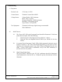
5. USER INTERFACE
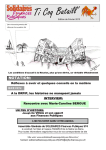
Operation of the User (Remote) Interface is essentially equivalent to the local front panel controls.
Each unit has been shipped from the factory in Remote mode. To change to Local mode operation,
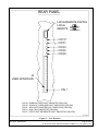
use the Local/Remote switch located on the rear panel. See Figure 1 for an illustration of the
Local/Remote switch and the Regulator connector located on the rear panel.
Functions that are underlined are operational in both Local and Remote modes. In addition, please
note that the local HV OFF switch is operational in both Local and Remote modes for safety reasons.
Pin Assignments- J4 (HV Regulator 9120010)
Pin #
Function (Input or Output)
1.
Voltage Reference (Input):
This high impedance input should be connected to a low impedance voltage source (less than or
equal to 1k ohms). A typical input would be the analog output of a computer interface. Zero volts
applied here is equal to a zero volt HV output, and +10V is equal to a -15.0kV HV output (0 to +10V
= 0 to -15.0kV).
2.
Common Pin for References (Input):
Connect to the return of the analog signal (or other voltage source) applied to pin 1.
3.
Current Reference (Input):
This high impedance input should be connected to a low impedance voltage source (less than or
equal to 1k ohms). A typical input would be the analog output of a computer interface. Zero volts
applied here is equal to a zero ampere HV output, and +10V is equal to a -1.111A HV output (0 to
+10V = 0 to -1.111A).
4.
Analog Voltage Monitor (Output):
This low impedance output should be connected to a high impedance load. A typical load would be
a voltmeter or the analog input of a computer interface. A micrometer or millimeter, in series with
an appropriate resistor, will function well. It is best if the resistor is adjustable so that the meter
calibration may be trimmed. Zero to +10V on this pin represents zero to -15.0kV HV output (0 to
+10V = 0 to -15.0kV). The source impedance for this signal is 1k ohm.
5.
Common Pin for Analog Monitors (Output):
Connect to negative terminal of meters or return of other measurement instrument applied to pins 4
and 6.
6.
Analog Current Monitor (Output):
This low impedance output should be connected to a high impedance load. A typical load would be
a voltmeter or the analog input of a computer interface. A micrometer or millimeter, in series with
an appropriate resistor, will function well. It is best if the resistor is adjustable so that the meter
calibration may be trimmed. Zero to +10V on this pin represents zero to -1.111A HV output (0 to
+10V = 0 to -1.111A). The source impedance for this signal is 1k ohm.
Document: MAN00238A
Page 12 of 28
R:\Documents\MAN Manuals\MAN00238A BRC-15-1111R-STD-J37.doc
7, 8. High Voltage OFF Control (Input):
Connect to a normally closed (NC) set of isolated ("voltage free" or "dry") switch contacts.
Operation of these contacts must be momentary (i.e. the contacts stay closed until the switch is
operated, at which time they open briefly, and the contacts automatically return to the closed state
after an operation).
9, 10.
External Interlock (Input):
Short these pins together to complete interlock loop.
11, 12.
High Voltage ON Control (Input):
Connect to a normally open (NO) set of isolated switch contacts. Operation of these contacts
should be momentary, but an alternate action switch is acceptable.
13.
Remote HV ON Monitor (Output):
This signal is +5VDC when HV is ON and is +0VDC when HV is OFF.
14.
Common Pin for High Voltage ON Control and Inhibit Command (Input):
Connect to return for Remote HV ON Monitor and Inhibit Command signals.
15.
Inhibit Command (Input):
This input is used to prevent high voltage from being turned on in any mode of operation. By
maintaining +5VDC on this pin (TTL high state), high voltage is prevented from being turned on
by the front panel pushbutton or the User Interface, and will terminate high voltage if in the ON
state.
Document: MAN00238A
Page 13 of 28
R:\Documents\MAN Manuals\MAN00238A BRC-15-1111R-STD-J37.doc
REAR PANEL
LOCAL/REMOTE SWITCH
LOCAL
REMOTE
CR137
CR131
CR133
CR135
CR139
J4
USER INTERFACE
PIN 1
CR139 - OVERVOLTAGE FAULT INDICATOR (YELLOW)
CR135 - 'SLOW' DC OVERLOAD FAULT INDICATOR (YELLOW)
CR133 - ARC RATE COUNTER FAULT INDICATOR (YELLOW)
CR131 - RAIL FAULT INDICATOR (YELLOW)
CR137 - STEP START SEQUENCE FAULT INDICATOR (YELLOW)
03-13-2002
Figure 1 – User Interface
Document: MAN00238A
Page 14 of 28
R:\Documents\MAN Manuals\MAN00238A BRC-15-1111R-STD-J37.doc
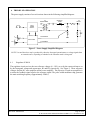
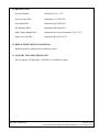
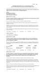
6. THEORY OF OPERATION
The power supply consists of several sections shown in the following simplified diagram:
HV
TRANSFORMER
RECTIFIER
FILTER
HV
OUTPUT
INPUT
POWER
CIRCUIT
V set
mA FEEDBACK
R1
REGULATOR
I set
kV FEEDBACK
R2
Figure 2 – Power Supply Simplified Diagram
NOTE: Vset and Iset above may be produced by either the front panel potentiometers or voltage signals from
an external source, depending on whether Local or Remote mode is being used.
6.1
Regulator 9120010
The regulator circuit receives the two reference voltages (0 - 10V), as set by the remote references or
by the front panel voltage and current pots, R1 and R2, respectively. See Figure 2. These reference
voltages feed the KV error amplifier and mA error amplifier. The objective of each error amplifier is
to make the feedback signal equal to the reference signal. The pulse width modulator chip generates
the main switching frequency (approximately 22kHz).
Document: MAN00238A
Page 15 of 28
R:\Documents\MAN Manuals\MAN00238A BRC-15-1111R-STD-J37.doc
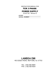
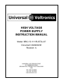
6.2
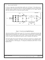
Power Card 853189539P
AC power is connected to a three phase bridge rectifier circuit. See Figure 3. The rectifiers power a
raw capacitive filter. The inverter switches, in a full bridge configuration, alternate the high voltage
transformer primary winding between the rail voltages established by the raw supply capacitors,
producing a bipolar square wave signal on the primary winding.
+
INVERTERS
RAIL
PRI
FILTER
AC
- RAIL
SEC
Figure 3 – Power Inverter Simplified Diagram
The inverter switches are IGBTs that are gated ‘ON’ for an interval established by the pulse width
modulator chip on the Regulator card. At power turn-on, the raw capacitor bank is charged through
rectifier CR12 and current limited by R42 and R43. When the initial charge period is complete,
relay K1 is energized, connecting the rail capacitors to the low impedance three-phase line.
The inverter IGBTs do not operate until the raw capacitors are charged, K1 is energized, and the
‘HV ON’ pushbutton is depressed. The IGBT gate signal originates on the Regulator board as
varying width pulses at a fixed frequency. The frequency is determined by R219 and C133 on the
Regulator board.
Document: MAN00238A
Page 16 of 28
R:\Documents\MAN Manuals\MAN00238A BRC-15-1111R-STD-J37.doc
7. HIGH VOLTAGE ON
Once the installation is complete, the power supply is ready to be energized. Turn on the system
power at the source circuit breaker box. To activate the control electronics, switch the front panel
breaker to the ON position. The ‘Power On’ indicator will be illuminated.
Local Mode
High voltage can be activated if all interlocks and faults are clear. To enable high voltage, press the
‘HV ON’ pushbutton. The white ‘HV ON’ light will illuminate indicating that there is high voltage
on the output. To turn the supply off, press the ‘HV OFF’ pushbutton. This will disable high
voltage and clear any faults.
The ‘kV Adjust’ knob and the ‘A Adjust’ knob must both be above zero to allow the power supply
to produce any output voltage or current. 3½ digit panel meters for output voltage and current have
been provided on the front panel. They facilitate easy interpretation of the output values at a glance.
LEDs below the front panel LCD displays indicate the mode of control, voltage regulation or current
regulation.
Remote Mode
If all interlocks and faults are clear, the User Interface can now be used to activate and control the
high voltage output. Refer to Section 5 for User Interface control details.
Document: MAN00238A
Page 17 of 28
R:\Documents\MAN Manuals\MAN00238A BRC-15-1111R-STD-J37.doc
8. SPECIFICATION
15.0kV 1.111A SWITCH MODE POWER SUPPLY
8.1 INPUT
Voltage
Phases:
Frequency:
Current:
208V ±10% (187-229V)
Three
50/60 Hertz
65A max.
8.2 OUTPUT
Voltage:
Current:
Polarity:
Regulation:
Ripple:
0 to -15.0kV DC
0 to -1.111A DC
Changeable (shipped as Negative)
± 0.1% (± 15.0V)
0.5% rms (75V rms) max.
8.3 LED INDICATORS (FRONT PANEL)
Power On
Fault
Positive
Negative
Kilovolts
Amperes
Indicates AC power is active
Indicates a power supply fault is present
Output polarity is positive
Output polarity is negative
Indicates when unit is in voltage regulation mode
Indicates when unit is in current regulation mode
8.4 LCD INDICATORS
Output Voltage Meter, 3.5 Digits, 15.0kV
Output Current Meter, 3.5 Digits, 1.111A
8.5 LOCAL CONTROL
Main Circuit Breaker
High Voltage ON pushbutton
High Voltage OFF pushbutton
kV Adjust knob
A Adjust knob
8.6 FEATURES
Oil-free design
High frequency switching technology
Document: MAN00238A
Page 18 of 28
R:\Documents\MAN Manuals\MAN00238A BRC-15-1111R-STD-J37.doc
8.6 REMOTE CONTROL
Reference Inputs
Voltage:
Current:
0 to +10V = 0 to -15.0kV DC
0 to +10V = 0 to -1.111A DC
Monitor Outputs
Voltage:
Current:
0 to -15.0kV DC = 0 to +10V DC
0 to -1.111A DC = 0 to +10V DC
Digital Signal Inputs
HV ON:
HV OFF:
Momentary contact closure
Momentary contact opening
Digital Signal Outputs
HV On:
TTL High
8.7 MECHANICAL
Panel
Chassis
Weight
HV Output
Control Interface
Power Input
Ground Connection
19” wide x 7” high max.
21” deep (not including approx. 2” for connections)
100 lbs (including packaging)
Fixed, rear panel
Phoenix MSTB-1.5/17-ST-508(or equivalent)
connector, rear panel (J4)
3-position terminal strip, rear panel
¼ – 20 stud, rear panel
8.8 FUSING
Regulator 9120010 (F1)
Regulator 9120010 (F3)
Inverter 853189539P (F1,2)
Bussmann GDC-100mA (250VAC, 0.1A, time delay)
Bussmann GDC-500mA (250VAC, 0.5A, time delay)
Bussmann GDB-4A (250AC, 4A, fast acting)
Document: MAN00238A
Page 19 of 28
R:\Documents\MAN Manuals\MAN00238A BRC-15-1111R-STD-J37.doc
9. CIRCUIT BOARD ADJUSTMENTS
Although each power supply is fully tested and calibrated prior to shipment, there are circuit boards
in the unit that may require adjustment at some time during the life of the power supply. These
boards are the Regulator board (9120010) and Front Panel board (9120021).
Before attempting to make any adjustments inside the power supply chassis, please be sure that the
consequences of such an adjustment are completely understood.
Do not attempt to make any adjustment unless you fully understand the function of each
potentiometer. These adjustments are preset by the manufacturer and should not be disturbed unless
you are experiencing difficulties.
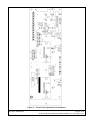
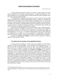
Refer to Figures 4 and 5 for the exact locations of adjustment potentiometers on the circuit boards
(PWAs) listed above. Also refer to the list on the following page, which will describe the function
of each potentiometer in detail.
For a detailed description of adjustment procedures, see the Acceptance Test Procedure called out in
Section 13.
Potentiometer Function Descriptions
Front Panel PWA
9120021:
Regulator PWA
9120010:
R6
R7
R9
Front panel voltmeter calibration.
Front panel ammeter calibration.
Shutdown timer one-shot period: sets length of time unit will stay in
the shutdown state after an arc or similar event.
R1
High voltage feedback divider AC compensation: adjusts AC gain of
feedback divider.
Divider current compensation: removes the loading effect (current
drain) of the internal feedback divider which would otherwise cause
an error in the current feedback signal.
kV Cal: calibrates the ratio between the voltage reference and the
actual output voltage when the unit is in voltage regulation mode.
mA Cal: calibrates the ratio between the current reference and the
actual output current when the unit is in current regulation mode.
kV Mon Cal: calibrates the ratio between the actual output voltage
and the monitor signal, which is fed to both the User Interface J4
connector on the rear panel and to the front panel voltage meter.
mA Mon Cal: calibrates the ratio between the actual output current
and the monitor signal, which is fed to both the User Interface J4
connector on the rear panel and to the front panel current meter.
R103
R25
R197
R83
R181
Document: MAN00238A
Page 20 of 28
R:\Documents\MAN Manuals\MAN00238A BRC-15-1111R-STD-J37.doc
R41
R149
R165
R137
R69
R125
Document: MAN00238A
Iavg OL Adjust: sets the sensitivity of the HV transformer’s average
primary current limit circuit. This protects the power inverter from
large values of average current over a period of many inverter
cycles. This circuit does not protect against high peaks of
instantaneous current.
Counter Adjust: sets the sensitivity of the arc counter circuitry which
shuts off high voltage if too many arcs or rollbacks occur in a given
period of time. It also functions as an arc rate circuit, since a rapid
succession of arcs is more apt to trip the circuit than the same
number of arcs spread out over a longer period of time.
Rail Fault Adjust: sets the trip point of a circuit which is sensitive to
excessive current in the power inverter. This type of fault could
indicate that an IGBT in the inverter has failed. This circuit has a
purpose similar, but not identical, to the “Iavg OL” circuit.
However, the rail fault circuit protects against more catastrophic
events, especially faults occurring within the inverter itself. It is a
latched fault, requiring a reapplication of ‘HV ON’ to resume HV
operation. DO NOT retry ‘HV ON’ more than once or twice after a
rail fault occurs, since this indicates damage has occurred within the
inverter and further attempts to turn on HV may worsen the damage.
Slow OC Adjust: sets the trip point of the slow responding overload
circuit, which monitors the output current. This circuit terminates
HV if the load demands an excessive amount of average current. It
is a latched fault, requiring a reapplication of ‘HV ON’ to resume
HV operation. (This circuit is normally set to approximately 5%
above the rated maximum load current). This circuit would function
well during an excessive increase in load which might not be
detected by the other protection circuitry.
OV Adjust: sets the threshold of the overvoltage circuitry, which
monitors the output voltage. This circuit terminates HV if it detects
voltage higher than the set point. The set point is factory adjusted to
5% above the maximum rating of the supply.
+10V Ref Adjust: calibrates the precision internal reference voltage
to +10.000V.
Page 21 of 28
R:\Documents\MAN Manuals\MAN00238A BRC-15-1111R-STD-J37.doc
HV REGULATOR PWA
REMOTE INTERFACE
Figure 4 – Regulator Adjustment Potentiometers
Document: MAN00238A
Page 22 of 28
R:\Documents\MAN Manuals\MAN00238A BRC-15-1111R-STD-J37.doc
Figure 5 – Front Panel Adjustment Potentiometers
Document: MAN00238A
Page 23 of 28
R:\Documents\MAN Manuals\MAN00238A BRC-15-1111R-STD-J37.doc
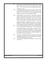
10. FAULTS / TROUBLESHOOTING
Faults
Overcurrent: If the output becomes shorted or if there is a surge in output current due to changes in
the load that exceed the rated current, then this circuit will be tripped. Its threshold is
set by R137. Once this circuit is tripped, HV is latched off. The power supply will
give a fault indication by lighting the ‘Fault’ LED permanently. The ‘HV ON’ light
will go out as well. This tells the user to correct the load and reactivate HV.
Both overload (or overcurrent) circuits are driven by a buffered current feedback
signal that is derived from a shunt resistor located in the high voltage section of the
power supply.
Overvoltage: Overvoltage is a fault which will rarely be tripped. Adjustable via R69, this circuit
will be activated when it senses output voltage which is greater than the set point. An
unstable system, due to load dynamics, may cause an overvoltage condition. This
circuit is driven by a buffered voltage feedback signal derived from the HV divider.
This fault will cause HV to be latched off and the Fault LED will light.
dV/dt:
(Change in Voltage per Change in Time) The source of a fault of this type is an
output arc, which causes a very large change in voltage in a short period of time.
This circuit is also driven by the voltage feedback. Like the fast OL fault, this type of
fault causes a rollback, which will not place the supply in a latched fault condition. It
merely temporarily interrupts high voltage so the condition can clear. The output
then recovers to the set point with little indication. The purpose for this type of
recovery is that permanent shutdowns or faults can become a nuisance when arcing is
a common occurrence in high voltage systems.
The dV/dt circuit is not adjustable.
AC Overload: The AC OL fault is the average primary current or "Avg OL" fault, which is more
sensitive when the unit is operating closer to its rated output voltage and current. It is
a slower responding circuit than the peak circuit and its main purpose is to limit
power output by triggering rollbacks. Sensitivity is adjusted via R41.
The AC OL fault circuits are non-latching. They act to keep the primary current in
the HV transformer from reaching excessive levels.
Rail Fault:
This circuit protects against excessively large current in the power inverter, which
may or may not be related to the primary current signal. However, the rail fault
circuit is used to protect against more catastrophic events than the typical output
conditions the primary current circuits were designed to withstand.
An imbalance in the voltage sharing of the power switches or a failed power switch
might be the cause of a rail fault. Thus, you will rarely (if ever) see this type of
latched fault. Like the other latched faults, this circuit will illuminate the Fault LED.
The sensitivity of this circuit is adjustable via R165.
Document: MAN00238A
Page 24 of 28
R:\Documents\MAN Manuals\MAN00238A BRC-15-1111R-STD-J37.doc
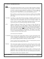
Rollbacks and the One-Shot Timer
As discussed previously, a rollback is distinct from a latched fault in that it does not shut high
voltage off permanently. A latched fault requires that an HV ON command be given again before
HV can be reactivated.
The non-latched circuits cause a brief rollback (or limiting action). This is the case for the fast
overload, dV/dt, peak primary current overload, and the average primary current overload circuits.
These circuits feed an additional circuit which controls the duration of time that the shutdown
condition is permitted to be present. This circuit is called the rollback timer and its duration (called
the rollback period) is adjustable via R9 on the front panel PCB. The rollback timer setting is one of
the key ingredients to arc recovery performance and is critical in many applications.
The one-shot period must be long enough to allow an output arc to extinguish before the power
supply begins to make output again. It should also allow sufficient time for the related electronics to
be "reset" or return to their nominal state. On the other hand, it must not be too long as to cause
operational difficulties.
Therefore, if problems are encountered which appear to be related to arc recovery, this potentiometer
behind the front panel may be adjusted until the desired performance is achieved. To see the effect
of this adjustment directly, it is helpful to use a storage oscilloscope to view the voltage monitor
output on the rear panel (J4, pin 4) while rollbacks are occurring. You can induce a rollback by
striking the output with a ground stick. As the rollback period is adjusted, you will see the off time
of the power supply vary. The off time begins the instant a rollback event occurs and ends at the
instant the output starts to rise again.
Document: MAN00238A
Page 25 of 28
R:\Documents\MAN Manuals\MAN00238A BRC-15-1111R-STD-J37.doc
Troubleshooting
A. Equipment
B.
Resistor Load:
13.5k ohms, 16.7kW
Current Sensor:
Tektronix Current Probe #P6021
Voltage Sensor:
Voltage Divider, 20kV minimum
Ratio: 500:1 or greater
Frequency Response: 100kHz minimum
Resistance: 10 megohms typical
Scope Probes: 10:1 and 100:1
Test Equipment:
Tektronix Oscilloscope, digital storage recommended
Fluke Multimeter
Initial Turn-on
1.0
The ‘Power ON’ LED on the front panel board should be illuminated. If the front
panel shows no lights, check the following:
1.
Check for power on the input power line (208VAC, 3-phase).
2.
Check the fuses on Regulator board 9120010 (see section 8.8 for fuse
details).
2.0
It is normal for the front panel ‘Fault’ LED to blink momentarily when the circuit
breaker is turned on. The ‘Fault’ LED should immediately go out, however if the
light does not extinguish, check if any fault LEDs are illuminated on the rear
panel. If one or more LED is illuminated, verify if the fault condition(s) is
present and correct if possible.
3.0
High Voltage Ready Status
The green ‘Ready’ indicator in the ‘HV ON’ pushbutton should be illuminated
when conditions are clear for HV on. If faults are present, this indicator will not
illuminate.
Document: MAN00238A
Page 26 of 28
R:\Documents\MAN Manuals\MAN00238A BRC-15-1111R-STD-J37.doc
C.
Common Causes for Faults
1. Over-temperature (symptom: unit deactivates HV; ‘Ready’ indicator briefly off)
a. Fan intake and/or outlet is blocked, preventing adequate airflow.
b. Ambient air temperature exceeds specifications.
2. Interlock (symptom: unit deactivates HV; ‘Ready’ indicator off)
a. Top cover interlock switch open.
b. Interlock loop on J4 not shorted.
3. Over-voltage Fault
a. Large inductive element connected to output.
b. Misconnection of output to external high voltage source.
4. Overload Fault
a. Effective load resistance too low; extreme dynamic load.
b. Large capacitive load connected to output.
c. HV output misconnected to ground.
5. dV/dt Fault (Arc Fault)
a. Load arcing.
b. Output connections with insufficient spacing for high voltages.
6. Rail Fault
a. Failed IGBTs or HV rectifier diodes
b. Large capacitive load connected to output.
c. HV output misconnected to ground.
Document: MAN00238A
Page 27 of 28
R:\Documents\MAN Manuals\MAN00238A BRC-15-1111R-STD-J37.doc
11. DRAWING LIST
System Schematic
(Schematic) D-6-7-1557
Power Inverter PWA
(Schematic) C-6-1895-39P
Front Panel PWA
(Schematic) D9120021-013
HV Regulator PWA
(Schematic) D9120010-011
High Voltage Module PWA
(Schematic) See System Schematic, D-6-7-1557
Output Low end PWA
(Schematic) B-6-1891-47AT
12. REPLACEMENT BILLS OF MATERIAL
Replacement bills of material are available on request.
13. FACTORY TEST PROCEDURE (ATP)
The Acceptance Test Procedure (ATP00255) is available on request.
Document: MAN00238A
Page 28 of 28
R:\Documents\MAN Manuals\MAN00238A BRC-15-1111R-STD-J37.doc