1
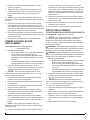
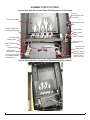
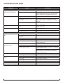
Service Manual
Model Number
VCX1525
VCX1525-WH
UL Part Number
6904000100
IMPORTANT SAFETY INFORMATION: Always read this manual first before attempting to service this
fireplace. For your safety, always comply with all warnings and safety instructions contained in this
manual to prevent personal injury or property damage.
Dimplex North America Limited
1367 Industrial Road Cambridge ON Canada N1R 7G8
1-888-346-7539 www.dimplex.com
In keeping with our policy of continuous product development, we reserve the right to make changes without notice.
© 2011 Dimplex North America Limited
REV
PCN
DATE
00
-
28-JUL-11
7400370000R00
TABLE OF CONTENTS
OPERATION. . . . . . . . . . . . . . . . . . . . . . . . . . . . . . . . . . . . . . . . . . . . . . . . . . . . . . . . . 3
MAINTENANCE . . . . . . . . . . . . . . . . . . . . . . . . . . . . . . . . . . . . . . . . . . . . . . . . . . . . . . 4
EXPLODED PARTS DIAGRAM. . . . . . . . . . . . . . . . . . . . . . . . . . . . . . . . . . . . . . . . . . 5
WIRING DIAGRAM. . . . . . . . . . . . . . . . . . . . . . . . . . . . . . . . . . . . . . . . . . . . . . . . . . . . 6
PREPARATION FOR SERVICE: . . . . . . . . . . . . . . . . . . . . . . . . . . . . . . . . . . . . . . . . . 7
HEATER ASSEMBLY REPLACEMENT . . . . . . . . . . . . . . . . . . . . . . . . . . . . . . . . . . . 8
LOWER LIGHT HARNESS REPLACEMENT . . . . . . . . . . . . . . . . . . . . . . . . . . . . . . . 8
UPPER LIGHT HARNESS REPLACEMENT. . . . . . . . . . . . . . . . . . . . . . . . . . . . . . . . 8
DIMMER CONTROL BOARD REPLACEMENT. . . . . . . . . . . . . . . . . . . . . . . . . . . . . 10
SWITCH REPLACEMENT . . . . . . . . . . . . . . . . . . . . . . . . . . . . . . . . . . . . . . . . . . . . . 10
3-POSITION SWITCH AND HEATER ON/OFF SWITCH. . . . . . . . . . . . . . . . . . . . . . . . . . . . . . . . . . . . . . . . . 10
THERMOSTAT CONTROL REPLACEMENT. . . . . . . . . . . . . . . . . . . . . . . . . . . . . . . . 11
FLICKER MOTOR/FLICKER ROD REPLACEMENT. . . . . . . . . . . . . . . . . . . . . . . . . . 11
POWER CORD REPLACEMENT. . . . . . . . . . . . . . . . . . . . . . . . . . . . . . . . . . . . . . . . . 11
ASSEMBLY PART PICTURES. . . . . . . . . . . . . . . . . . . . . . . . . . . . . . . . . . . . . . . . . . 12
TROUBLESHOOTING GUIDE. . . . . . . . . . . . . . . . . . . . . . . . . . . . . . . . . . . . . . . . . . 16
Always use a qualified technician or service agency to repair this fireplace.
! NOTE: Procedures and techniques that are considered important enough to emphasize.
CAUTION: Procedures and techniques which, if not carefully followed, will result in damage to the
equipment.
Warning: Procedures and techniques which, if not carefully followed, will expose the user to the
risk of fire, serious injury, or death.
2
www.dimplex.com
OPERATION
The controls are located on the right hand side of the
fireplace (Figure 1).
Figure 1
back on.
CAUTION: If you need to continuously reset the heater,
disconnect power and call Dimplex customer service at
1-888-DIMPLEX (1-888-346-7539).
Remote Control
B
The fireplace is supplied with a radio frequency remote
control. This remote control has a range of approximately
50 feet (15.25 m), it does not have to be pointed at the
fireplace and can pass through most obstacles (including
walls). It is supplied with one of hundreds of independent
frequencies to prevent interference with other units.
! NOTE: Before attempting any operation with the
remote, pull the plastic insulator strip out from between
the remote casing and battery cover (Figure 2).
A
Remote Operation
D
C
A. 3-Position Switch
The switch has two ON positions marked with and “ON”.
The “ON” position is for manual operation. In this position
the built-in remote control is by-passed.
The position is for operating the unit with the provided
remote control.
When in position the unit is operated with the ON and
OFF buttons of the remote control.
When the switch is in the center position the unit is off.
B. Heater On/Off Switch
The Heater On/Off Switch supplies power to the heater fan
and the heater element.
When the switch is in the ON position the heater operates if
the thermostat calls for heat.
C. Heater Thermostat Control
To adjust the temperature to your individual requirements,
turn the thermostat control upward all the way to turn on the
heater. When the room reaches the desired temperature,
turn the thermostat knob downward until you hear a click.
Leave in this position to maintain the room temperature at
this setting. For additional heat, turn upward until you hear
the click again and the heater will turn on.
D. Top Light Dimmer Control
The top Top Light Dimmer Control controls the brightness
of the top accent light that is used to illuminate the pebbles
Resetting The Temperature Cutoff Switch
Should the heater overheat, an automatic cut out will turn
the fireplace off and it will not come back on without being
reset. It can be reset by switching the 3-Position Switch to
OFF and waiting five (5) minutes before switching the unit
The fireplace is supplied with an integrated on/off remote
control
! NOTE: Ensure that the fireplace 3-Position Switch is set
to the remote control setting.
To operate, push the ON button to turn fireplace on, push
the OFF button to turn the fireplace off.
Remote Control Initialization/Reprogramming
If the remote control or receiver has been replaced, follow
these steps to initialize the remote control and receiver:
1. Set the 3-Position switch to OFF.
2. Wait a minimum of five (5) seconds and set the 3
Position Switch to the position.
3. Within 10 seconds of re-acquiring power, press the ON
button located on the remote control.
! NOTE: You will have only 10 seconds to perform this
last step. Failure to do so will result in these steps needing
to be followed again.
This will synchronize the remote control and receiver.
Battery Replacement
To replace the battery:
1. Slide battery cover open on the remote control
(Figure 2).
2. Install one (1) 12-Volt (A23) battery in the battery
holder.
3. Close the battery cover
Figure 2
On
Button
Off Button
Plastic
Strip
Battery must
be recycled or
disposed of
properly. Check with
your Local Authority or
Retailer for recycling
advice in your area.
Battery
Cover
3
MAINTENANCE
⑥ Replace with new bulbs.
WARNING: Disconnect power before attempting any
maintenance or cleaning to reduce the risk of fire,
electric shock or damage to persons.
Light Bulb Replacement
Turn unit off, allow at least five (5) minutes for light bulbs to
cool before touching bulbs to avoid accidental burning of
skin.
Light bulbs need to be replaced when you notice a dark
section of the flame. There are two (2) bulbs, which
generate the flames.
Tool Requirements: Philips screw driver
Helpful Hints - It is a good idea to replace all light bulbs at
once if they are close to the end of their rated life. Group
replacement will reduce the number of times you will need
to open the unit to replace light bulbs.
Light Bulb Requirements: Quantity of two (2) 60 Watt
chandelier or candelabra bulbs with E-12 (small) socket
base, 120 Volt.
Do not exceed 60 Watt per bulb
⑦ Reassemble light block and glass assembly in reverse
order.
Glass Cleaning
The front glass is cleaned in the factory during the
assembly operation. During shipment, installation,
handling, etc., the front glass may collect dust particles,
these can be removed by dusting lightly with a clean dry
cloth.
To remove fingerprints or other marks, the glass can be
cleaned with a damp cloth. The glass should be completely
dried with a lint free cloth to prevent water spots. To
prevent scratching, do not use abrasive cleaners or spray
liquids on the glass surface.
Fireplace Surface Cleaning
To remove fingerprints or other marks, the exterior finish
can be cleaned with a damp cloth with a mild detergent.
The surface should be completely dried with a lint free cloth
to prevent water spots.
To prevent scratching, do not use abrasive cleaners or
spray liquids on any surface.
Bulb Replacement Instructions:
① Disconnect power supply to the fireplace either by
unplugging the fireplace or switch off at the breaker panel.
Figure 4
② Remove glass assembly. Remove the screws securing
the glass assembly on the chassis (Figure 3).
③ Hold on to the glass assembly with both hands then lift
the whole assembly straight up to remove (Figure 4).
④ Remove the two (2) screws securing the light block as
Glass
Assembly
Lift to
Remove
shown in Figure 5, then remove the light block.
⑤ Reach in and turn the burnt bulb(s) counterclockwise to
remove.
Figure 5
Figure 3
Ensure Glass
Assembly
brackets engage
hooks on fireplace
by sliding Glass
Assembly towards
fireplace and then
down
Light
Block
Secure Glass
Assembly with the
four (4) supplied
self-tapping screws
4
www.dimplex.com
EXPLODED PARTS DIAGRAM
4
3
17
11
12
18
10
2
5
16
8
7
9
6
1
13
15
REPLACEMENT PARTS LIST
1. Front Glass . . . . . . . . . . . . . . . . . . . . . . 5901170100RP
VCX1525WH. . . . . . . . . . . . . . . . . . . . . 5901170200RP
2. Flicker Motor. . . . . . . . . . . . . . . . . . . . . 2000210300RP
3. Flicker Rod . . . . . . . . . . . . . . . . . . . . . . 5901110100RP
4. Lower Light Harness . . . . . . . . . . . . . . 4200121000RP
5. Partially Reflective Glass. . . . . . . . . . . . 5901180100RP
6. Thermostat . . . . . . . . . . . . . . . . . . . . . 2300150100RP*
7. On/Off Heater Switch . . . . . . . . . . . . . . 2800070700RP
8. Thermostat Control Knob . . . . . . . . . . . 8801080100RP
9. 3-Position Switch . . . . . . . . . . . . . . . . . . 2800071100RP
10. Remote Control Receiver . . . . . . . . . . . 3000380200RP
11. Terminal Block . . . . . . . . . . . . . . . . . . . .4000070100RP
12. Heater Assembly . . . . . . . . . . . . . . . . . .6904280200RP
13. Power Cord . . . . . . . . . . . . . . . . . . . . . .4100090104RP
14. Upper Light Harness. . . . . . . . . . . . . . . 2500400400RP
15. Dimmer Control. . . . . . . . . . . . . . . . . . . 3000250100RP
16. Dimmer Control Knob . . . . . . . . . . . . . . 8800000600RP
17. Remote Control. . . . . . . . . . . . . . . . . . . 3000370500RP
18. Media Tray Retaining Bracket . . . . . . . .1020410159RP
19. Black Stone Media . . . . . . . . . . . . . . . . 1400050100RP
20. River Rock Media (VCX1525WH) . . . . .1400080100RP
21. Cutout . . . . . . . . . . . . . . . . . . . . . . . . . . 2300201200RP
22. Hardware Kit. . . . . . . . . . . . . . . . . . . VCX1525WH-HW
5
JUNCTION
BOX
BLOWER
MOTOR
WIRE ENCAPSULATING
HEAT SLEEVE COMPLIANT
TO UL 1026 STANDARD AND
RATED AT 200°C MINIMUM
HEATING ELEMENT
LIGHT BULB
THERMO CUTOUT
LIGHT BULB
LIGHT BULB
FLICKER
MOTOR
CAPACITOR
TERMINAL
BLOCK
FLICKER MOTOR
WIRE HARNESS
L
R/C
N
INTEGRAL ON-OFF
REMOTE CONTROL
WIRE ENCAPSULATING
HEAT SLEEVE COMPLIANT
TO UL 1026 STANDARD AND
RATED AT 200°C MINIMUM
2
OFF
REMOTE
MANUAL
HEAT ON
HEAT OFF
2
THERMOSTAT
3
1
1
WIRING DIAGRAM
6
www.dimplex.com
PREPARATION FOR SERVICE:
Tools Required: Philips head screwdriver
Wire Cutter
Figure 6
! IMPORTANT: Please proceed with the following
steps in preparation for replacement of ONLY the following parts.
• Heater Assembly
• Lower Light Harness Assembly
These preparation instructions do not apply to the
flicker motor; upper light harness; the switches or thermostat replacement.
WARNING: If the fireplace was operating prior to servicing, allow at least 10 minutes for light bulbs and heating
elements to cool off to avoid accidental burning of skin.
WARNING: Disconnect power before attempting any
maintenance to reduce the risk of electric shock or damage
to persons.
1. Remove glass assembly:
• Remove the screws securing the glass assembly
on the bottom of the chassis. (Figure 3)
• Hold on to the glass assembly with both hands
and lift the whole assembly straight up to remove.
(Figure 4)
• Set glass assembly aside in an upright position so
that the pebbles don’t fall out of the top opening.
2. Remove the fireplace from the wall:
i. Surface Mount: partially loosen the screws from the
keyhole mount openings on the back panel. Loosen
approximately 1/8th of an inch, just enough to lift the
unit off the mounting screws.
! NOTE: Take note of which keyholes were used for
mounting so it can be put back into the same position
once service is complete.
ii. Partial Recessed Mount: Remove the 4 wood
screws attached to the back panel, located on top and
bottom of both the left and right side of the unit, releasing it from framed wall opening.
3. Disconnect power before attempting any maintenance.
! NOTE: This unit may have been installed to a power
source in one of 2 ways:
• Option #1 – Plugged into an outlet: a power cord with
plug, inserted into an outlet near or behind the fireplace, unplug the fireplace from the outlet.
• Option #2 – Hardwire connection: power supplied from
electrical wire coming from a dedicated, properly fused
circuit with 120 Volt, 15 Amp rating directly from the
main electrical panel, turn the breaker off at the electrical panel.
• It is recommended during original installation,
there should be an allowance of up to 8 feet of
service cable for connecting power supply to the
junction box on fireplace.
Hard wire connection can be accessed from inside the
front lower left of the unit if the fireplace is still mounted
in the wall. If unit has already been dismounted, the
wires can also be accessed from underneath the by
removing the screw from the wire housing cover plate.
4. Once the fireplace is removed off of the wall and the
wires from the power source have been disconnected,
lay the fireplace on a solid surface on its front.
! NOTE: If you are laying the unit on a finished surface
that is prone to scratching, be sure to cover the work surface with a protective cover.
5. Remove the 9 screws to remove the inner back panel
from the outer panel: 4 left, 4 right, 1 lower center of
the back panel. (Figure 6)
6. Carefully turn the fireplace over onto it’s back.
7. Remove the 4 screws that attach the flame panel to the
exterior side panel of the fireplace: 2 on the left and 2
on the right. (Located approx. 6” inches from the bottom).
8. Remove the 7 screws from the heater assembly cover:
3 on the front of the cover, 2 on the bottom left and 2
on the bottom right of the chassis – (on the left and
right side of the bottom vent). Set the heater assembly
cover aside.
9. Remove the 4 screws that secure the heater assembly
housing to the bottom of the chassis. The screws are
located above and below the heat vent.
10. Cut the wire-tie located in the bottom center area of the
light-harness mounting panel, (just above the heater
assembly). This will allow the flame panel to slide up
more freely.
7
11. Grasp the heater assembly and slide the heater assembly and rear reflective flame panel up, just enough
to reach inside and remove the black wire attached on
the right side of the dimmer control board. By removing this wire you will then have the ability to move the
assembly without damaging the receiver.
12. After the black wire has been removed from the dimmer control board, move the heater assembly with the
rear flame panel farther up into the unit until the panel
clears the receiver on the bottom right panel.
13. Carefully pull the flame panel up and out of the fireplace chassis. Some force will be required when sliding and removing this panel.
14. Proceed to the correct “Replacement Instructions” in
the following pages for the part in need of repair, (either
heater assembly, remote control receiver, or lower light
harness).
HEATER ASSEMBLY REPLACEMENT
Tools Required: Philips head screwdriver
Wire Cutter
CAUTION: Follow “Preparation for Service” instructions
before proceeding.
1. With the rear flame panel released, carefully turn the
rear flame panel over and remove the 6 screws that
hold the heater assembly bracket to this panel. (2) on
the left flange, (2) on the right flange, (2) on the bottom
flange. Once heater assembly is free, lay the flame
panel and the heater assembly back down, resting
inside the fireplace.
2. Locate the switch housing cover plate to the right of
the heater assembly. Remove the 2 mounting screws
located on the exterior chassis and free the cover plate
from its location.
! NOTE: Wires from the thermostat will still be attached so the cover won’t completely come out. You can
just lift and turn it a ¼ turn, then rest it inside the fireplace
opening.
3. Remove the 2 heater assembly mounting brackets off
the rear left and the right of the blower motor and fan.
Each bracket has 2 screws securing it to the blower
assembly.
4. Remove 4 screws on the heat deflector panel attached
at the elements and attach it on the same location on
the new heater assembly.
5. Attach the mounting brackets to the new heater assembly in the same location as the original heater.
6. Remove the wire connections on the original blower
motor; elements; as well as the screw holding the high
limit cutout to the heater. Connect these wires and
screw onto the new heater assembly and back on to
the Heater On/Off switch and remote control receiver in
the same positions as the original connections.
! NOTE: Using a flat head screwdriver gently pry between the end of the connector and the heater to release
the wires.
7. Re-assemble in reverse order as described above
LOWER LIGHT HARNESS
REPLACEMENT
Tools Required: Philips head screwdriver
Wire Cutter
CAUTION: Follow “Preparation for Service” instructions
before proceeding.
1. With the rear flame panel has been released, carefully
turn the rear flame panel over and remove the 4 screws
that hold the heater assembly bracket to this panel.
Once heater assembly is free, lay the flame panel and
the heater assembly back down, resting inside the
fireplace.
2. Remove the 3 screws from the rear flame panel that
secure the light harness housing to this back panel.
! NOTE: This will allow for better access to the lower
light harness.
3. Remove the two (2) screws securing the light block as
shown in Figure 6, then remove the light block.
4. Remove the bulbs by turning them counter clockwise.
5. Remove the screws in each relative terminal on the
terminal block, which secure the blue and white wires
from the light harness.
! NOTE: Be sure to note the original configuration of
the wires on the terminal block.
6. Cut the wire ties that secure the wire harness to the
light harness mounting panel.
7. From underneath the mounting panel, remove the
small screw in each socket, which secures the sockets
to the panel.
8. Feed the sockets through the opening on the housing
panel. You may have to rotate the socket slightly to get
them out.
9. Feed the new sockets into the mounting panel and secure with the small screw to the panel. The wires that
connect the two sockets should rest in the ledge, which
is attached to the bottom of the light harness mounting
panel.
10. Connect the new wire harness into the terminal block
according to the original configuration.
11. Reassemble in the reverse order as above.
UPPER LIGHT HARNESS
REPLACEMENT
Tools required: Phillips head screw driver.
Wire Cutter
WARNING: If the fireplace was operating prior to servicing, allow at least 10 minutes for light bulbs and heating
elements to cool off to avoid accidental burning of skin.
WARNING: Unplug (if applicable) or disconnect power
at the circuit breaker before attempting any maintenance to
reduce the risk of electric shock or damage to persons.
8
www.dimplex.com
1. Remove glass assembly:
2. Remove the screws securing the glass assembly on
the bottom of the chassis (Figure 4).
3. Hold on to the glass assembly with both hands and lift
the whole assembly straight up to remove (Figure 5).
4. Set glass assembly aside in an upright position so that
the pebbles don’t fall out of the top opening.
5. Locate the socket and the wire harness at the top of
the fireplace.
6. Remove the light bulb from the socket by turning it
counter clockwise.
7. Unscrew the socket ring off the socket and remove the
socket out of the socket mounting bracket.
8. Cut the wire harness at the 3rd wire tie on the top panel
coming from the socket.
9. With pliers, squeeze the grommet that secures the
socket as well as the short end of the cut wire harness
to the top panel, and pull the socket with the wire out of
the panel.
! NOTE: If possible, wire ties should be left in place to
re-use on the new wire harness.
10. Insert the new wire harness into the opening down
through the top panel.
11. Remove the socket ring off the new socket..
12. Insert the new socket into the socket mounting bracket
and secure to the bracket by reconnecting the socket
ring.
13. Cut the new harness leaving approximately 8 inches
of length to reach from the opening on the top panel
to just below the corner where the top meets the back
panel of the fireplace.
14. Feed the new wire harness through the wire ties, which
secure the light harness to the top of the unit.
15. Connect the original wire harness still inside the fireplace to the new wire harness coming from the top by
stripping the ends approx. ¼ - ½ inch off each of the
4 wires. Connect the wires together with a wire-nut,
matching blue to blue; and white to white).
! NOTE: You want minimal wiring hanging down from
the top, and the connection should be as close as possible
to the back corner in order to minimize the chance of the
connection being seen through the partially reflective glass,
which will sit in front once unit is re-assembled.
16. Re-assembly in reverse order as shown above.
REMOTE Control Receiver REPLACEMENT
Tools Required: Philips head screwdriver
Needle Nose Pliers
1. Remove glass assembly:
• Remove the screws securing the glass assembly
on the bottom of the chassis (Figure 4).
• Hold on to the glass assembly with both hands
and lift the whole assembly straight up to remove
(Figure 5).
Set glass assembly aside in an upright position so
that the pebbles don’t fall out of the top opening.
2. With the unit facing up, remove the bottom panel by
removing the screws around the outside of the panel
(11) and the 8 screws on the bottom. (Figure 7)
•
Figure 7
Figure 8
Figure 9
Top Light Dimmer
Thermostat
Heater On/Off Switch
3-Position Switch
9
3. Remove the remaining 3 screws holding the center
panel on. (Figure 8)
4. Taking note of the original location of each wire connected to the board, remove each wire and connect
them onto the same location on the new receiver
board.
! NOTE: Using a flat head screwdriver gently pry between the end of the connector and the receiver to release
the wires.
5. Remove the original receiver board off the 4 plastic
mounting tabs on each corner of the receiver. To do
this, squeeze each mounting tab flange/post either by
hand or by or with a pair of needle nose pliers until they
are depressed enough to pull the board off.
6. Once the original board is free from the tabs, align the
new board over the mounting tabs and gently press the
board onto the tabs.
7. Re-assemble in reverse order as described above.
DIMMER CONTROL BOARD
REPLACEMENT
Tools Required: Philips head screwdriver
Needle Nose Pliers
1. Remove glass assembly:
• Remove the screws securing the glass assembly
on the bottom of the chassis (Figure 4).
• Hold on to the glass assembly with both hands
and lift the whole assembly straight up to remove
(Figure 5).
• Set glass assembly aside in an upright position so
that the pebbles don’t fall out of the top opening.
2. Locate the switch housing cover plate (Figure 9).
Remove the 2 mounting screws located on the exterior
chassis and free the cover plate from its location.
! NOTE: Wires from the thermostat will still be attached so the cover won’t completely come out. You can
just rest it inside the opening.
3. Pull the dial off the dimmer controller/potentiometer
located on the switch housing panel.
4. Remove the nut that secures the potentiometer to the
housing panel.
5. Replace with the new potentiometer and secure with
the nut from the original one.
6. With the unit facing up, remove the bottom panel by
removing the screws around the outside of the panel
(11) and the 6 in the middle. (Figure 7)
7. Gently pull the panel away from the unit and taking
note of the original location, remove each wire and connect them onto the same location on the new control
board.
! NOTE: Using a flat head screwdriver gently pry
between the end of the connector and the control board to
release the wires.
8. Remove the original receiver off the 4 plastic mount-
ing tabs on each corner of the receiver. To do this,
squeeze each mounting tab flange/post either by hand
or by or with a pair of needle nose pliers until they are
depressed enough to pull the board off. The tabs can
also be cut off and replaced with new ones that come
with the board.
9. Once the original board is free from the tabs, align the
new board over the mounting tabs and gently press the
board onto the tabs.
10. Reconnect the wires onto the new board in the same
orientation as the original.
11. Re-assemble in reverse order as described above.
SWITCH REPLACEMENT
3-POSITION SWITCH AND HEATER ON/OFF SWITCH
Tools required: Phillips head screw driver.
! NOTE: Your fireplace has both a 3-Position Switch
as well as a Heater On/Off switch, both of which are
located in the same area on the fireplace; are similar in
design; and can be replaced in the same way by following
the instructions below.
WARNING: If the fireplace was operating prior to servicing, allow at least 10 minutes for light bulbs and heating
elements to cool off to avoid accidental burning of skin.
WARNING: Unplug (if applicable) or disconnect power
at the circuit breaker before attempting any maintenance to
reduce the risk of electric shock or damage to persons.
1. Remove glass assembly:
• Remove the screws securing the glass assembly
on the bottom of the chassis (Figure 4).
• Hold on to the glass assembly with both hands
and lift the whole assembly straight up to remove
(Figure 5).
• Set glass assembly aside in an upright position so
that the pebbles don’t fall out of the top opening.
2. Locate the switch housing cover plate. Remove the 2
mounting screws located on the exterior chassis and
free the cover plate from its location.
! NOTE: Wires from the thermostat will still be attached; therefore, the cover plate won’t completely come
out. You can just rest it inside the opening.
3. Locate the switch to be replaced.
4. Disconnect the wiring connections noting their original
locations.
5. Depress the retainer clips on 2 sides of the switch and
push the switch out from the casing cover.
6. Properly orient the new switch and connect all of the
wiring connections according to the original configuration.
7. Reassemble in the reverse order as above.
10
www.dimplex.com
THERMOSTAT CONTROL
REPLACEMENT
Tools required: Phillips head screwdriver.
WARNING: If the fireplace was operating prior to servicing allow at least 10 minutes for light bulbs and heating
elements to cool off to avoid accidental burning of skin.
WARNING: Unplug (if applicable) or disconnect power
at the circuit breaker before attempting any maintenance to
reduce the risk of electric shock or damage to persons.
1. Remove glass assembly:
• Remove the screws securing the glass assembly
on the bottom of the chassis (Figure 4).
• Hold on to the glass assembly with both hands
and lift the whole assembly straight up to remove
(Figure 5).
• Set glass assembly aside in an upright position so
that the pebbles don’t fall out of the top opening.
2. Locate the switch housing on the right side of the fireplace. Remove the 2 mounting screws located on the
exterior face of the switch housing to free it from the
fireplace.
! NOTE: Wires from the thermostat will still be attached; therefore, the cover plate won’t completely come
out. You can just rest it inside the opening.
3. Remove the 2 screws on the face of the housing
holding the thermostat mounting bracket to the switch
housing.
4. Remove the thermostat dial by pulling it straight off the
shaft of the thermostat control.
5. Remove the 2 small screws that hold the thermostat to
the mounting bracket.
6. Disconnect the wiring connections noting their original
locations.
7. Properly orient the new thermostat and attach it to the
original mounting bracket.
8. Connect all of the wiring connections according to the
original configuration.
9. Reassemble in the reverse order as above.
FLICKER MOTOR/FLICKER ROD
REPLACEMENT
Tools Required: Phillips head screwdrivers
WARNING: If the fireplace was operating prior to servicing allow at least 10 minutes for light bulbs and heating
elements to cool off to avoid accidental burning of skin.
WARNING: Unplug (if applicable) or disconnect power
at the circuit breaker before attempting any maintenance to
reduce the risk of electric shock or damage to persons.
1. Remove glass assembly:
• Remove the screws securing the glass assembly
on the bottom of the chassis (Figure 4).
• Hold on to the glass assembly with both hands
and lift the whole assembly straight up to remove
(Figure 5).
Set glass assembly aside in an upright position so
that the pebbles don’t fall out of the top opening.
2. Remove the 7 screws from the heater assembly cover,
(3) on the front of the cover, (2) on the bottom left and
(2) on the bottom right of the chassis.
3. Locate the switch housing cover plate. Remove the 2
mounting screws located on the exterior chassis and
free the cover plate from its location.
•
! NOTE: Wires from the thermostat will still be attached; therefore, the cover plate won’t completely come
out. You can just rest it inside the opening.
4. Remove the flicker rod from the flicker assembly by
pulling and twisting the rubber channel section of the
rod away from the flicker motor.
5. With the stubby Philips screwdriver, disconnect the wiring connections of the flicker motor and the capacitor
from the terminal block noting their original locations.
! NOTE: The capacitor will be re-used. Be sure to
note which terminal and wires it’s connected to for re-installation.
6. With the stubby Philips screwdriver, remove the 2
screws that secure the flicker motor to the flicker bracket and remove the motor, sliding the wires out through
the protective sheath held by the wire ties and through
the casing opening just below the motor.
7. Mount the new flicker motor to the flicker bracket.
8. Feed the wires from the new motor back through the
casing and protective sheath.
9. Connect the wires and the capacitor back into the
terminal block.
10. Re-attach the flicker rod to the motor by inserting the
rod into the plastic bushing on the left and then pushing
the rod with the rubber connector onto the motor shaft.
11. Reassemble following steps 1 - 4 in the reverse order.
POWER CORD REPLACEMENT
Tools Required: Philips head screwdriver
1. Remove the 1 screw that secures the power cord cover
plate to the bottom of the fireplace.
2. Disconnect the 2 wire nuts that attach the power cord
to the black (L1) and the white (N) wires coming from
the inside of the fireplace.
! NOTE: (The green wire should be capped by itself
since it is not necessary with a polarized power cord).
3. With a pair of pliers, squeeze the strain relief bushing
that secures the power cord to the cover plate and pull
the bushing with the wire out of the plate.
4. Insert the new power cord through the opening on the
cover plate with the bare ends facing the inside of the
fireplace. Secure the stripped end of the power cord
to the plate with the replacement strain relief bushing
leaving approximately 2 ½ - 3 inches of length to go
inside the fireplace.
11
ASSEMBLY PART PICTURES
Interior View with Rear Flame Panel Still Attached to the Chassis
Dimmer Potentiometer Control & Dial
Rear Flame Panel
Thermostat Control
Dial
Flicker Rod & Left
Bushing & Bracket
Flicker Motor
Heater On/Off
Switch
Terminal Block
Blower Motor
High Temperature
Cutout
Heater Assembly
Left Element
Connections
Power Cord Connection (hidden behind
blower Motor)
3-Position Switch
Remote Control
Receiver
Right Element
Connections
Dimmer Control
Board (Beneath
Heater in front
of the receiver)
Interior View with Rear Flame Panel Detached from the Chassis
12
www.dimplex.com
Heater Assembly
High Temperature
Cutout
Blower Motor
Elements
Remote Control Receiver
“L” - Connects to Remote side of the 3-Position
Switch
Switch Output - Connects to On side of the 3-Position Switch
- “Piggy Back” Connects to High
Temperature Thermal Cutout
Switch Output - Connects to Upper Light Bulb
- “Piggy Back” Terminal Block and
Blower Motor
13
Dimmer Control Board
“P2” - Connects to the
Potentiometer
“P” - Connects to the Terminal Block
“P1” - Connects to the
Potentiometer
“L” - Connects to Upper Lights
Terminal Block
Connects to Capacitor and Flicker Motor
Capacitor
Connects to the Lower Light Assembly and the
Remote Control Receiver
Connects to Capacitor and Flicker Motor
Empty
Connects to the “On” side of the Heater Switch
and the Lower Light Assembly
Connects to Flicker Motor
Switch Housing Interior View
Heater On/Off
Switch
Connects to Thermostat
3 Position Switch
Connects to the Terminal Block and the High
Temperature Cutout
Connects to Switch Output on Remote Control
Receiver
Power Cord
Connects to the “L” on the Remote Control
Receiver
14
www.dimplex.com
Lower Interior View
Rear Flame Panel
Lower Light Assembly
Flicker Rod
Flicker Motor
Interior View Thermostat and Dimmer Control/
Potentiometer - Dial Removed
Interior View Thermostat and Dimmer Control/
Potentiometer - Dial attached
15
TROUBLESHOOTING GUIDE
Problem
Cause
Solution
General
Circuit breaker trips or fuse
blows when unit is turned on
Short in unit wiring.
Trace wiring in unit.
Improper circuit current rating
Additional appliances may exceed the current rating
of the circuit breaker or fuse. Plug unit into another
outlet or install unit on a dedicated 15 amp circuit.
Unit turns on or off by itself
Remote control has a similar frequency
to other remotes in the area.
Replace Remote Control. Initialize to Remote Control
Receiver.
Radio frequency disturbance from outside sources.
Replace Remote Control and Remote Control Receiver where necessary. Initialize Remote Control and
Receiver.
Defective Remote Control Receiver
Replace Remote Control Receiver. Initialize Remote
Control and Receiver.
Lights dim in room while the unit
is on
Unit is drawing close to circuit current
rating
Move the unit to another outlet or install unit on a dedicated 15 amp circuit
Power cord gets warm
Normal Operation
The power cord may get slightly warm to the touch
when the heater is on
Defective power cord
Replace power cord if cord gets hot to the touch.
Appearance
Fireplace does not turn on Manu- Improper operation
ally
No incoming voltage from the electrical
wall socket
Fireplace does not turn on using
the Remote Control
Refer to Operation Section
Check Fuse/Breaker Panel
Loose wiring
Check wiring connections
Defective 3-Position On/Off switch
Replace 3-Position On/Off switch
Defective Remote Control Receiver
Replace Remote Control Receiver. Initialize Remote
Control and Receiver.
Improper operation
Refer to Operation Section
Remote control not initialized to fireplace
Initialize the remote control
Defective remote control
Install new battery into the remote contol. Reinitialize
remote where necessary
Replace Remote Control Receiver or Remote Control
where necessary. Initialize Remover Control and
Remote Control Receiver
Flame Frozen
Defective Flicker motor
Replace Flicker motor
Loose wiring
Check wiring connections
Burnt out light bulbs
Replace light bulbs
Loose wiring
Check wiring connections
Defective light harness
Replace light harness
Log set dim, not glowing
Burnt out light bulbs
Replace light bulbs
Flame Shudder
Defective Flicker motor
Replace Flicker motor
Light leaking around the log set
Log set not positioned properly
Check log set for proper fit
Flame not bright or flame not
visible
16
www.dimplex.com
Problem
Cause
Solution
Heater
Heater is not turning off
Heater is not turning on
Heater is turning off after a
couple of minutes of operation
Heater emits an odor
Heater fan turns on but heater
lacks heat
Improper operation
Refer to Operation Section
Defective heater on/off switch
Replace heater on/off switch
Defective thermostat
Replace thermostat
Defective Remote Control Receiver
Replace Remote Control Receiver
Improper operation
Refer to Operation Section
Loose wiring
Trace wiring in unit.
Defective heater on/off switch
Replace heater on/off switch
Defective thermostat
Replace thermostat
Defective heater assembly
Replace heater assembly
Build up of dirt/dust in heater assembly
Ensure that exterior intake louvers and firebox cavity
are free of dirt/dust.
Defective Heater Assembly
Replace Heater Assembly
Normal Operation
Normal operation is when the heater emits an odor
for a brief period after the heater is initially turned on.
The heater is burning off any dust accumulated during
manufacturing or operation.
Defective heater assembly
Replace heater assembly
Improper operation
Refer to Operation Section
Defective thermostat
Replace thermostat
Loose wiring
Trace wiring in unit
Defective heater assembly
Replace heater assembly
Normal Operation
Small glowing sections of the element are considered
normal.
Defective heater assembly
If larger glowing sections are causing the heater to trip
the thermal cutout, unplug unit, discontinue use and
replace heater assembly.
Loose wiring
Trace wiring in unit
Defective heater on/off switch
Replace heater on/off switch
Defective thermostat
Replace thermostat
Defective heater assembly
Replace heater assembly
Excessive noise with the heater
on
Dirty heater assembly
Ensure that exterior intake louvers and firebox cavity
are free of dirt/dust.
Defective heater assembly
Replace heater assembly
Grinding or excessive noise with
the heater off
Moving Flicker rod hitting or rubbing
against internal components
Ensure rod is straight and mounted properly in the
bracket, spinning freely away from other components.
Replace if necessary.
Defective Flicker motor
Replace Flicker motor
Heating element is glowing red
Heater fan runs continuously
Noise
17