1
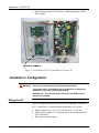
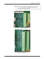
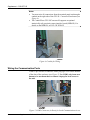
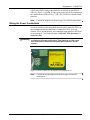
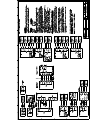
Supplement CW-GFC-IS Part Number: D301646X012 November, 2009 ControlWave GFC-IS Supplement to: CI-ControlWave GFC / CI-ControlWave Corrector Intrinsically Safe (IS) Gas Flow Computer / Corrector Remote Automation Solutions www.EmersonProcess.com/Remote IMPORTANT! READ INSTRUCTIONS BEFORE STARTING! Be sure that these instructions are carefully read and understood before any operation is attempted. Improper use of this device in some applications may result in damage or injury. The user is urged to keep this book filed in a convenient location for future reference. These instructions may not cover all details or variations in equipment or cover every possible situation to be met in connection with installation, operation or maintenance. Should problems arise that are not covered sufficiently in the text, the purchaser is advised to contact Emerson Process Management, Remote Automation Solutions division (RAS) for further information. EQUIPMENT APPLICATION WARNING The customer should note that a failure of this instrument or system, for whatever reason, may leave an operating process without protection. Depending upon the application, this could result in possible damage to property or injury to persons. It is suggested that the purchaser review the need for additional backup equipment or provide alternate means of protection such as alarm devices, output limiting, fail-safe valves, relief valves, emergency shutoffs, emergency switches, etc. If additional information is required, the purchaser is advised to contact RAS. RETURNED EQUIPMENT WARNING When returning any equipment to RAS for repairs or evaluation, please note the following: The party sending such materials is responsible to ensure that the materials returned to RAS are clean to safe levels, as such levels are defined and/or determined by applicable federal, state and/or local law regulations or codes. Such party agrees to indemnify RAS and save RAS harmless from any liability or damage which RAS may incur or suffer due to such party's failure to so act. ELECTRICAL GROUNDING Metal enclosures and exposed metal parts of electrical instruments must be grounded in accordance with OSHA rules and regulations pertaining to "Design Safety Standards for Electrical Systems," 29 CFR, Part 1910, Subpart S, dated: April 16, 1981 (OSHA rulings are in agreement with the National Electrical Code). The grounding requirement is also applicable to mechanical or pneumatic instruments that include electrically operated devices such as lights, switches, relays, alarms, or chart drives. EQUIPMENT DAMAGE FROM ELECTROSTATIC DISCHARGE VOLTAGE This product contains sensitive electronic components that can be damaged by exposure to an electrostatic discharge (ESD) voltage. Depending on the magnitude and duration of the ESD, this can result in erratic operation or complete failure of the equipment. Read supplemental document S14006 for proper care and handling of ESD-sensitive components. Remote Automation Solutions A Division of Emerson Process Management 1100 Buckingham Street, Watertown, CT 06795 Telephone (860) 945-2200 Emerson Process Management Training GET THE MOST FROM YOUR EMERSON INSTRUMENT OR SYSTEM Avoid Delays and problems in getting your system on-line Minimize installation, start-up and maintenance costs. Make the most effective use of our hardware and software. Know your system. As you know, a well-trained staff is essential to your operation. Emerson offers a full schedule of classes conducted by full-time, professional instructors. Classes are offered throughout the year at various locations. By participating in our training, your personnel can learn how to install, calibrate, configure, program and maintain your Emerson products and realize the full potential of your system. For information or to enroll in any class, go to http://www.EmersonProcess.com/Remote and click on “Training” or contact our training department in Watertown at (860) 945-2200. BLANK PAGE Supplement – CW-GFC-IS Chapter 1 – Introduction This supplement describes the differences in installation and setup between the intrinsically safe (IS) versions of the ControlWave Gas Flow Computer (GFC) / ControlWave Corrector and the standard versions of these devices. Overview The intrinsically safe features of the ControlWave GFC-IS / ControlWave Corrector-IS are designed to prevent sparks or release of energy that could ignite a hazardous atmosphere and cause an explosion. Differences between the Standard and IS Versions There are several differences between the ControlWave GFC / ControlWave Corrector and the ControlWave GFC-IS / ControlWave Corrector-IS: Issued Nov-09 Unlike the standard GFC/Corrector, the GFC-IS/Corrector-IS operates in Class I Division 1 hazardous locations. To ensure the integrity of the intrinsically-safe rating, the CPU and I/O boards are located behind a shield in the enclosure and all wiring termination blocks are on a termination panel. When replacing the battery, replace the shield to preserve the intrinsic safety integrity. The internal lead acid battery is a special sealed type with internal protection (part number 396924-01-8). The GFC-IS/Corrector-IS does not support an internal case-mounted radio or modem. The only supported communication methods for the GFCIS/Corrector-IS are serial RS-232 communication through COM1 and COM2, and serial RS-485 communication through COM3. The RS-485 interface can be connected to a 3808 transmitter for an additional meter run. Communication to devices outside the hazardous area requires the ISTRAN (Intrinsically Safe Communication Interface unit). See CICW-GFC-ISTRAN for more information. The only GFC-IS/Corrector-IS CPU speed is 14 MHz. The GFC-IS/Corrector-IS power supply only operates from +5.4V to 8V (+6V nominal input power). DO NOT USE alternate power input connector (P6). The GFC-IS/Corrector-IS has no auxiliary power output. The GFC-IS/Corrector-IS does not support a polyphaser. The GFC-IS/Corrector-IS does not have an analog output (AO) option. Digital outputs have a V max of 10Vdc and an I max of 250 mA. Analog inputs support 1-5V operation only. They do not support 420 mA operation. Supplement to CI-ControlWave GFC / CI-ControlWave Corrector 1 Supplement – CW-GFC-IS Pulse/DI inputs on the CPU board are 10 kHz high speed counter (HSC) inputs. Figure 1. ControlWave GFC-IS / ControlWave Corrector-IS Chapter 2 – Installation / Configuration Warning To ensure safe use of this product, please review and follow the instructions in the following supplemental documentation: Supplement Guide - ControlWave Site Considerations for Equipment Installation, Grounding, and Wiring (S1400CW) ESDS Manual – Care and Handling of PC Boards and ESD Sensitive Components (S14006) Wiring the I/O There are certain differences between I/O in the standard ControlWave GFC / ControlWave Corrector and the intrinsically safe version: 2 Digital outputs have a V max of 10Vdc and an I max of 250 mA. Analog inputs support 1-5V operation only. They do not support 420 mA operation. There are no analog outputs. Supplement to CI-ControlWave GFC / CI-ControlWave Corrector Issued Nov-09 Supplement – CW-GFC-IS Note: Wire all I/O to connectors TB3 and TB4 (see Figure 3 and Figure 4). Consult the wiring diagram at the end of this document for terminal connections. Figure 2. Terminal Block TB3 Figure 3. Terminal Block TB4 Issued Nov-09 Supplement to CI-ControlWave GFC / CI-ControlWave Corrector 3 Supplement – CW-GFC-IS Notes: You must wire all connections from the terminal panel out through a conduit on the right side of the GFC-IS / Corrector-IS enclosure (see Figure 4). The ControlWave GFC-IS/Corrector-IS supports an optional intrinsically safe proximity sensor interface board (ISPROX). For details on the ISPROX, see PIP-CW ISPROX. Figure 4. Conduit for Wiring Wiring the Communication Ports COM1 is pre-wired to a connector with a plug-type cover on the bottom of the door of the enclosure (see Figure 5). Use COM1 only in an area known to be non-hazardous to connect a laptop for local access to the unit. Figure 5. COM1 Connector (in Door) for Local Communication Access 4 Supplement to CI-ControlWave GFC / CI-ControlWave Corrector Issued Nov-09 Supplement – CW-GFC-IS COM2 and COM3 wiring connections are located on terminal block TB3 (See Figure 2). Wiring for these ports routes out of the unit through the conduit to the ISTRAN. See CI-CW-GFC-ISTRAN for details on the interface. Note: Consult the diagram on the next page for terminal connections. Wiring the Power Connections You must connect power using both the solar panel connector (TB1) on the termination panel and the battery 1 connector (TB2). You can connect TB2 to an intrinsically safe communication interface (ISTRAN) or an internal 6V 7AH lead acid battery. DO NOT USE the battery 2 connector (P6). Warning Only use battery and solar panels shipped from the factory with the unit according to the model specification. Using batteries or solar panels from third parties violates the intrinsically safe certification for the system. Figure 6. Power Connectors for Solar Panel and Battery 1 Note: Issued Nov-09 Consult the wiring diagram on the next page for terminal connections. Supplement to CI-ControlWave GFC / CI-ControlWave Corrector 5 Supplement – CW-GFC-IS The following tables detail the model specification for the ControlWave GFC-IS / ControlWave Corrector-IS: MODEL NUMBER FORMAT: CWM-GFC-1- ABC-D-E-F-G-H-J-K-L-M-N-O-P-Q-R DIFFERENTIAL / STATIC PRESSURE RANGE (When using differential / static pressure, substitute one of these Range Codes for ABC in model number) Description Range Code (ABC) NO SENSOR 000 150” WC / 1000 PSI 121 150” WC / 2000 PSI 122 150” WC / 500 PSI 123 100” WC / 2000 PSI 132 300” WC / 1000 PSI 141 300” WC / 2000 PSI 142 25 PSI / 2000 PSI 202 25 PSI / 4000 PSI 204 GAGE PRESSURE RANGE (When using gage pressure, substitute one of these Range Codes for ABC in model number) Description Range Code (ABC) 300” WC 014 25 PSI 020 100 PSI 022 300 PSI 023 1000 PSI 025 2000 PSI 028 STATIC PRESSURE FLANGE ORIENTATION (Substitute one of these flange codes for D in the model number) Description Note Upstream left First digit of range code (A) must be 1 or 2. Flange Code (D) 1 Upstream right First digit of range code (A) must be 1 or 2. 2 None, correct no counter First digit of range code (A) must be 0. 3 Counter with index (CW) First digit of range code (A) must be 0. 4 Counter with index (CCW) First digit of range code (A) must be 0. 5 Issued Nov-09 Supplement to CI-ControlWave GFC / CI-ControlWave Corrector 7 Supplement – CW-GFC-IS MODEL NUMBER FORMAT: CWM-GFC-1- ABC-D-E-F-G-H-J-K-L-M-N-O-P-Q-R ENCLOSURE (Substitute one of these enclosure codes for E in the model number) Description Note 2-button First digit of range code (A) must be 1 or 2. Enclosure Code (E) 2 25-button First digit of range code (A) must be 1 or 2. 3 2-button First digit of range code (A) must be 0. 5 25-button First digit of range code (A) must be 0. 6 MOUNTING HARDWARE (Substitute one of these mounting hardware codes for F in the model number) Description Note Mounting Hardware Code (F) 0 Process mount First digit of range code (A) or mounting kit (P) must be 1 or 2. Pole mount First digit of range code (A) or mounting kit (P) may be 0, 1, or 2. 1 PROCESSOR (Substitute one of these processor codes for G in the model number) Description Processor Code (G) 2 14 MHz CPU 5.4 to 8 Vdc powered, Intrinsic rated. Includes 10 kHz counter and RS 485 port. APPLICATION PROGRAM (Substitute one of these program codes for H in the model number) Description Note No application Unit ships from factory without an application Program Code (H) 0 Base 2-Run measurement application 1 TeleFlow Emulator 3 POWER SYSTEM (Substitute one of these power system codes for J in the model number) Description Note External Unit ships from factory without a power system. Adding an external power supply does not meet UL intrinsically safe certification. 1 6V, 7AH lead acid battery with 1W, 6V solar panel system This is an intrinsically safe system as it ships from the factory. You cannot substitute other third-party batteries/solar panels without voiding UL intrinsically safe certification. 4 6V, 7AH lead acid battery with 6W, 6V solar panel system This is an intrinsically safe system as it ships from the factory. You cannot substitute other third-party batteries/solar panels without voiding UL intrinsically safe certification. 5 8 Supplement to CI-ControlWave GFC / CI-ControlWave Corrector Power System Code (J) Issued Nov-09 Supplement – CW-GFC-IS MODEL NUMBER FORMAT: CWM-GFC-1- ABC-D-E-F-G-H-J-K-L-M-N-O-P-Q-R RTD (Substitute one of these RTD codes for K in the model number) Description Note RTD Code (K) No RTD included Sealed plug in space for RTD 0 12 in bendable RTD with 6 ft cable length Bendable RTD must be used with a thermo well. 1 12 in bendable RTD with 15 ft cable length Bendable RTD must be used with a thermo well. 2 12 in bendable RTD with 25 ft cable length Bendable RTD must be used with a thermo well. 3 RTD THERMO WELL OPTIONS (Substitute one of these thermo well codes for L in the model number) NOTE: THERMO WELL IS REQUIRED TO PREVENT POSSIBLE RTD BLOWOUT DUE TO PIPELINE PRESSURE. Description Note Thermo well Code (L) None This option applies only if thermo well is already installed or will be supplied from another source. 0 2.5 in insertion length 316 SS thermo well 1 4.5 in insertion length 316 SS thermo well 2 7.5 in insertion length 316 SS thermo well 3 I/O OPTIONS (Substitute one of these I/O codes for M in the model number) Description Note I/O Code (M) None No I/O 0 2 DI/DO, 4 DI, 2 DO, 2 HSC 2 DI/DO, 4 DI, 2 DO, 2 HSC 1 2 DI/DO, 4 DI, 2 DO, 2 HSC, 3 AI 2 DI/DO, 4 DI, 2 DO, 2 HSC, 3 Ai 2 ISTRAN (Intrinsically Safe Communication Interface) OPTIONS (Substitute one of these ISTRAN codes for N in the model number) Description ISTRAN Code (N) None / ISTRAN Ready 0 ISTRAN installed 1 ISPROX OPTIONS (Intrinsically Safe Proximity Sensor Interface Board) (Substitute one of these ISPROX codes for O in the model number) Description Note None No ISPROX installed. 0 ISPROX installed and connected to CPU HSC Flange code (D) must be 1, 2, or 3. 1 ISPROX installed and connected to CPU HSC Input 2 Flange code (D) must be 4 or 5. 1 ISPROX installed and connected to process I/O terminal “LS” Flange code (D) must be 4 or 5. 2 Issued Nov-09 Supplement to CI-ControlWave GFC / CI-ControlWave Corrector ISPROX Code (O) 9 Supplement – CW-GFC-IS MODEL NUMBER FORMAT: CWM-GFC-1- ABC-D-E-F-G-H-J-K-L-M-N-O-P-Q-R MOUNTING KIT (Substitute one of these mounting kit codes for P in the model number) Description Note Mounting Kit Code (P) None Mounting hardware code (F) must be 0 or 1 0 Standard (Rockwell, Roots type) Mounting hardware code (F) must be 0 1 American Meter Type Mounting hardware code (F) must be 0 2 DIGIT BLANKING (Substitute one of these digit blanking codes for Q in the model number) Description Digit Blanking Code (Q) None 0 st 1 digit (tenths) nd 2 1 digit (ones) 2 rd 3 digit (tens) 3 METER INDEX RATE (Substitute one of these meter index rate codes for R in the model number) Description Meter Index Rate Code (R) None 0 1 CF/REV 1 5 CF/REV 2 10 CF/REV 3 100 CF/REV 4 1000 CF/REV 5 3 0.1 M /REV 6 3 1 M /REV 7 3 8 10 M /REV 3 100 M /REV 10 9 Supplement to CI-ControlWave GFC / CI-ControlWave Corrector Issued Nov-09 WARRANTY A. Remote Automation Solutions (RAS) warrants that goods described herein and manufactured by RAS are free from defects in material and workmanship for one year from the date of shipment unless otherwise agreed to by RAS in writing. B. RAS warrants that goods repaired by it pursuant to the warranty are free from defects in material and workmanship for a period to the end of the original warranty or ninety (90) days from the date of delivery of repaired goods, whichever is longer. C. Warranties on goods sold by, but not manufactured by RAS are expressly limited to the terms of the warranties given by the manufacturer of such goods. D. All warranties are terminated in the event that the goods or systems or any part thereof are (i) misused, abused or otherwise damaged, (ii) repaired, altered or modified without RAS consent, (iii) not installed, maintained and operated in strict compliance with instructions furnished by RAS or (iv) worn, injured or damaged from abnormal or abusive use in service time. E. These warranties are expressly in lieu of all other warranties express or implied (including without limitation warranties as to merchantability and fitness for a particular purpose), and no warranties, express or implied, nor any representations, promises, or statements have been made by RAS unless endorsed herein in writing. Further, there are no warranties which extend beyond the description of the face hereof. F. No agent of RAS is authorized to assume any liability for it or to make any written or oral warranties beyond those set forth herein. REMEDIES A. Buyer's sole remedy for breach of any warranty is limited exclusively to repair or replacement without cost to Buyer of any goods or parts found by Seller to be defective if Buyer notifies RAS in writing of the alleged defect within ten (10) days of discovery of the alleged defect and within the warranty period stated above, and if the Buyer returns such goods to the RAS Watertown office, unless the RAS Watertown office designates a different location, transportation prepaid, within thirty (30) days of the sending of such notification and which upon examination by RAS proves to be defective in material and workmanship. RAS is not responsible for any costs of removal, dismantling or reinstallation of allegedly defective or defective goods. If a Buyer does not wish to ship the product back to RAS, the Buyer can arrange to have a RAS service person come to the site. The Service person's transportation time and expenses will be for the account of the Buyer. However, labor for warranty work during normal working hours is not chargeable. B. Under no circumstances will RAS be liable for incidental or consequential damages resulting from breach of any agreement relating to items included in this quotation from use of the information herein or from the purchase or use by Buyer, its employees or other parties of goods sold under said agreement. How to return material for Repair or Exchange Before a product can be returned to Remote Automation Solutions (RAS) for repair, upgrade, exchange, or to verify proper operation, Form (GBU 13.01) must be completed in order to obtain a RA (Return Authorization) number and thus ensure an optimal lead time. Completing the form is very important since the information permits the RAS Watertown Repair Dept. to effectively and efficiently process the repair order. You can easily obtain a RA number by: A. FAX Completing the form (GBU 13.01) and faxing it to (860) 945-2220. A RAS Repair Dept. representative will return the call (or other requested method) with a RA number. B. E-MAIL Accessing the form (GBU 13.01) via the RAS Web site (www.emersonprocess.com/remote) and sending it via E-Mail to [email protected] . A RAS Repair Dept. representative will return E-Mail (or other requested method) with a RA number. C. Mail Mail the form (GBU 13.01) to Remote Automation Solutions A Division of Emerson Process Management Repair Dept. 1100 Buckingham Street Watertown, CT 06795 A RAS Repair Dept. representative will return call (or other requested method) with a RA number. D. Phone Calling the RAS Repair Department at (860) 945-2442. A RAS Repair Department representative will record a RA number on the form and complete Part I, send the form to the Customer via fax (or other requested method) for Customer completion of Parts II & III. A copy of the completed Repair Authorization Form with issued RA number should be included with the product being returned. This will allow us to quickly track, repair, and return your product to you. Remote Automation Solutions Repair Authorization Form (Providing this information will permit Remote Automation Solutions to effectively and efficiently process your return. Completion is required to receive optimal lead time. Lack of information may result in increased lead times.) Date ____________ RA # _________________ Standard Repair Practice is as follows: Variations to this is practice may be requested in the “Special Requests” section. • Evaluate / Test / Verify Discrepancy/Repair/Replace SH Line No. _________ Please be aware of the Non warranty standard charge: • There is a $100 minimum evaluation charge. The party sending in material is responsible to ensure that the materials returned are clean to safe levels, defined and/or determined by applicable federal, state and /or local law regulations or codes. Such party agrees to indemnify Remote Automation Solutions harmless to any liability or damage which Remote Automation Solutions may incur or suffer due to such party’s failure to so act. Part I Please complete the following information for single unit or multiple unit returns Address No. _____________ Address No. ____________ Bill to : _____________________________________ Ship to: ___________________________________ ____________________________________________ ____________________________________________ ____________________________________________ ____________________________________________ Purchase Order: _________________________ Contact Name: _____________________________ Phone: _____________________ Part II Fax: ______________________ E-Mail: ______________________ Please complete Parts II & III for each unit returned Model No./Part No. _________________________ Description: __________________________________ Range/Calibration: _________________________ S/N: ___________________________________ Reason for return : Failure Upgrade Verify Operation Other __________________________ 1. Describe the conditions of the failure (Frequency/Intermittent, Physical Damage, Environmental Conditions, Communication, CPU watchdog, etc.) ___________________ (Attach a separate sheet if necessary) 2. Comm. interface used: Standalone RS-485 Ethernet Other: ______________________________________ Modem (PLM (2W or 4W) or SNW) 3. What is the Firmware revision?_______________ What is the Software & version? _______________ Part III If checking “replaced” for any question below, check an alternate option if replacement is not available A. If product is deemed not repairable would you like your product: returned replaced B. If Remote Automation Solutions is unable to verify the discrepancy, would you like the product: replaced scrapped? returned *see below? * Continue investigating by contacting the customer to learn more about the problem experienced? The person to contact that has the most knowledge of the problem is: __________________ phone _________________ If we are unable to contact this person the backup person is:________________ phone _________________ Special Requests: __________________________________________________________________________________________ Ship prepaid to: Form GBU 13.01 Remote Automation Solutions, Repair Dept., 1100 Buckingham Street, Watertown, CT 06795 Phone: 860-945-2442 Fax: 860-945-2220 Rev. F 11/25/08 BLANK PAGE BLANK PAGE Supplement to CI-ControlWave GFC / CI-ControlWave Corrector Supplement CW-GFC-IS November, 2009 NOTICE Emerson Process Management Remote Automation Solutions 1100 Buckingham Street Watertown, CT 06795 Phone: +1 (860) 945-2262 Fax: +1 (860) 945-2525 www.EmersonProcess.com/Remote Emerson Process Management Remote Automation Solutions 6338 Viscount Rd. Mississauga, Ont. L4V 1H3 Canada Phone: 905-362-0880 Fax: 905-362-0882 www.EmersonProcess.com/Remote Emerson Process Management SA de CV Calle 10 #145 Col. San Pedro de los Pinos 01180 Mexico, D.F. Mexico T +52 (55) 5809-5300 F +52 (55) 2614-8663 www.EmersonProcess.com/Remote Emerson Process Management, Ltd. Remote Automation Solutions Blackpole Road Worcester, WR3 8YB United Kingdom Phone: +44 1905 856950 Fax: +44 1905 856969 www.EmersonProcess.com/Remote Emerson Process Management AP Pte Ltd. Remote Automation Solutions Division 1 Pandan Crescent Singapore 128461 Phone: +65-6770-8584 Fax: +65-6891-7841 www.EmersonProcess.com/Remote “Remote Automation Solutions (“RAS”), division of Emerson Process Management shall not be liable for technical or editorial errors in this manual or omissions from this manual. RAS MAKES NO WARRANTIES, EXPRESSED OR IMPLIED, INCLUDING THE IMPLIED WARRANTIES OF MERCHANTABILITY AND FITNESS FOR A PARTICULAR PURPOSE WITH RESPECT TO THIS MANUAL AND, IN NO EVENT SHALL RAS BE LIABLE FOR ANY INCIDENTAL, PUNITIVE, SPECIAL OR CONSEQUENTIAL DAMAGES INCLUDING, BUT NOT LIMITED TO, LOSS OF PRODUCTION, LOSS OF PROFITS, LOSS OF REVENUE OR USE AND COSTS INCURRED INCLUDING WITHOUT LIMITATION FOR CAPITAL, FUEL AND POWER, AND CLAIMS OF THIRD PARTIES. Bristol, Inc., Bristol Babcock Ltd, Bristol Canada, BBI SA de CV and the Flow Computer Division are wholly owned subsidiaries of Emerson Electric Co. doing business as Remote Automation Solutions (“RAS”), a division of Emerson Process Management. FloBoss, ROCLINK, Bristol, Bristol Babcock, ControlWave, TeleFlow and Helicoid are trademarks of RAS. AMS, PlantWeb and the PlantWeb logo are marks of Emerson Electric Co. The Emerson logo is a trademark and service mark of the Emerson Electric Co. All other trademarks are property of their respective owners. The contents of this publication are presented for informational purposes only. While every effort has been made to ensure informational accuracy, they are not to be construed as warranties or guarantees, express or implied, regarding the products or services described herein or their use or applicability. RAS reserves the right to modify or improve the designs or specifications of such products at any time without notice. All sales are governed by RAS’ terms and conditions which are available upon request. © 2009 Remote Automation Solutions, division of Emerson Process Management. All rights reserved.