1
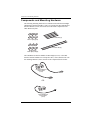
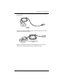
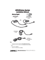
GPS/Wireless System
Installation Manual
GPS/Wireless
Interface Module
# 8127
GPS/Wireless
Interface Module
# 8251
– OR –
GPS Module
# 8128
Wireless
On-Board Module
# 8129
For:
• GPS/Wireless Interface Module for DriveRight (# 8127) OR
• GPS/Wireless Interface Module for CarChip Fleet Pro (# 8251)
AND
• GPS Module (# 8128)
• Wireless On-Board Module (# 8129)
®
3465 Diablo Ave., Hayward, CA 94545-2778 USA
( 510 ) 732-9229 t FAX ( 510 ) 670-0589 t [email protected] t www.davisnet.com
Regulatory Compliance
E Mark
This product complies with the essential protection requirements of the EC EMC Vehicle Directive 95/54/EC.
CE EC EMC Compliance
This product complies with the essential protection requirements of the EC EMC Directive 89/336/EC.
FCC Part 15.247
FCC ID: OUR-XBEEPRO
IC RSS-210
IC ID: 4214A-XBEEPRO
FCC Part 15 Class B Registration Warning
This equipment has been tested and found to comply with the limits for a Class B digital device, pursuant to Part 15 of the
FCC Rules. These limits are designed to provide reasonable protection against harmful interference in a residential installation. This equipment generates, uses, and can radiate radio frequency energy and, if not installed and used in accordance
with the instructions, may cause harmful interference to radio communications.
However, there is no guarantee that interference will not occur in a particular installation. If this equipment does cause harmful interference to radio or television reception, which can be determined by turning the equipment on and off, the user is
encouraged to try to correct the interference by one or more of the following measures:
• Reorient or relocate the receiving antenna.
• Increase the separation between the equipment and receiver.
• Connect the equipment into an outlet on a circuit different from that to which the receiver is connected.
• Consult the dealer or an experienced radio/TV technician for help.
Changes or modification not expressly approved in writing by Davis Instruments may void the warranty and void the user's
authority to operate this equipment.
For Products: # 8127, # 8128, # 8129, # 8251
Rev. E (6/8/11)
GPS/Wireless System Installation Manual
Document Number: 7395.221
© Davis Instruments Corp. 2011. All rights reserved.Contents subject to change without notice
®
®
DriveRight and CarChip are registered trademarks of Davis Instruments Corp. VELCRO® is a registered trademark of Velcro Industries B. V.
Davis Instruments Quality Management System is ISO 9001 certified.
®
3465 Diablo Avenue, Hayward, CA 94545-2778 U.S.A.
510-732-9229 • Fax: 510-732-9188
E-mail: [email protected] • www.davisnet.com
GPS/Wireless System
Installation Manual
This manual provides the instructions necessary to install the GPS Module
(# 8128), and the Wireless On-Board Module (# 8129) with your DriveRight®
600E device using the DriveRight GPS/Wireless Interface Module
(# 8127) or with your CarChip® Fleet Pro using the CarChip Fleet Pro GPS/
Wireless Interface Module (# 8251).
The DriveRight GPS/Wireless Interface Module (# 8127) connects the GPS
and/or Wireless On-Board Modules to a DriveRight 600E device. The CarChip
Fleet Pro GPS/Wireless Interface Module (# 8251) connects the GPS and/or
Wireless On-Board Modules to a CarChip Fleet Pro.
Refer to the DriveRight 600E User’s Guide, or CarChip Fleet Pro User’s
Guide, and the DriveRight Fleet Management Software Online Help for more
information on configuring and using these components.
Note: GPS data collection must be enabled in the DriveRight or CarChip device prior to
installation in the vehicle via the DriveRight Fleet Management Software (FMS).
The Wireless On-Board Module must be configured in the Fleet Management Software
(FMS) before installation in a vehicle.
See the FMS Online Help System for information on configuring both of these modules.
The components necessary for a GPS/Wireless System installation in a vehicle
differ based on the monitoring device with which the components are paired.
Device
DriveRight 600E
# 8126
CarChip Fleet Pro
# 8246
GPS/Wireless
Interface Device
DriveRight GPS/
Wireless Interface
Module #
8127*
CarChip GPS/
Wireless Interface
Module #
8251*
GPS Device
Wireless Device
GPS Module
# 8128
Wireless On-Board
Module # 8129
GPS Module
# 8128
Wireless On-Board
Module # 8129
*Requires one # 8127 GPS/Wireless Interface Module (for DriveRight installations)
or one # 8251 f(or CarChip Fleet Pro installation) per vehicle.
1
Components and Mounting Hardware
Components and Mounting Hardware
The following mounting hardware kit is included with either the DriveRight
GPS/Wireless Interface Module (# 8127) or CarChip Fleet Pro GPS/Wireless
Interface Module (# 8251) and can be used with all the components in the
GPS /Wireless System:
5.5'' Cable Ties (4)
®
Velcro Tape (6 pair)
12'' Cable Ties (2)
Double-Sided
Foam Tape (6 strips)
The GPS/Wireless Interface Module for DriveRight (# 8127) or the GPS/
Wireless Interface Module for CarChip Fleet Pro (# 8251) should come with
the mounting hardware (above) and one of the components shown below:
DriveRight GPS\Wireless
Interface Module
(# 8127)
-OR-
CarChip GPS/Wireless
Interface Module
(# 8251)
2
Components and Mounting Hardware
The GPS Module (# 8128) is sold separately and comes with the component
shown below:
GPS Module
(# 8128)
The Wireless On-Board Module (# 8129) is also sold separately and comes
with the component shown below:
Wireless On-Board Module
(# 8129)
Both the GPS Module and Wireless On-Board Module work with both
GPS/Wireless Interface Modules shown on the previous page.
3
DriveRight GPS/Wireless Wiring Diagram
DriveRight GPS/Wireless Wiring Diagram
The following wiring diagrams display all the possible wiring solutions for
connecting the GPS/Wireless Interface Module, GPS Module, and Wireless
On-Board Module to an existing DriveRight 600E system.
4
# 8128
GPS
Module
# 8127
GPS/Wireless
Interface Module
(Part of remaining wiring for
DriveRight 600E installation;
not shown.)
Digital Adapter
Cable
GPS
W
8′ Cable
(244 cm)
# 8129
Wireless
On-Board
Module
# 8126
# 8104 or # 8105
(optional)
SmartCard
On-Board
Reader
DriveRight 600E
Wiring the GPS/Wireless System with a DriveRight 600E
DriveRight GPS/Wireless Wiring Diagram
Making Connections
The GPS/Wireless Interface Module for DriveRight can be installed with
either the GPS Module, the Wireless On-Board Module or both. The
instructions below assume an installation involving all three modules.
Modify your own installation as necessary.
1. Connect the GPS Module to the GPS/Wireless Interface Module by
plugging the male connector of the GPS Module cable into the socket
labeled “GPS” on the GPS/Wireless Interface Module.
2. Connect the Wireless On-Board Module to the GPS/Wireless Interface
Module by plugging the male connector on the Wireless On-Board Module
cable into the socket labeled “W” on the GPS/Wireless Interface Module.
3. Disconnect the DriveRight 600E device or optional SmartCard On-Board
Reader cable from the Digital Adapter Cable.
4. Connect the male connector from the GPS/Wireless Interface Module cable
to the female connector on the Digital Adapter Cable.
5. Connect the female connector on the GPS/Wireless Interface Module to the
male connector on the DriveRight 600E, or optional SmartCard On-Board
Reader cable.
See the diagrams below for properly disconnecting and connecting cables:
Disconnecting Cables:
Hold both cables by their connector housing and pull apart.
The housing of the male connector slides to separate the cables.
Connecting Cables:
Slide
Connector Housing
Hold the female connector and push the male connector from behind the housing, allowing
the housing to slide back. The cables lock together when a connection is made.
5
CarChip GPS/Wireless Wiring Diagrams
CarChip GPS/Wireless Wiring Diagrams
Wiring the GPS Wireless System to a CarChip Fleet Pro
CarChip Fleet Pro
# 8246
GPS\
Wireless
Interface
Module
# 8251
GPS
W
GPS
Module
# 8128
Wireless
On-Board
Module
# 8129
Making Connections
The GPS/Wireless Interface Module for CarChip Fleet Pro can be installed
with either the GPS Module, the Wireless On-Board Module or both. The
instructions below assume an installation involving all three modules.
Modify your own installation as necessary.
1. Connect the GPS Module to the GPS/Wireless Interface Module by
plugging the male connector of the GPS Module cable into the socket
labeled “GPS” on the GPS/Wireless Interface Module.
2. Connect the Wireless On-Board Module to the GPS/Wireless Interface
Module by plugging the male connector on the Wireless On-Board Module
cable into the socket labeled “W” on the GPS/Wireless Interface Module.
3. Connect the GPS/Wireless Interface module to CarChip Fleet Pro by plugging the male connector on the Module cable into the connector on the top
of the CarChip Fleet Pro.
6
Installing the GPS/Wireless System
Installing the GPS/Wireless System
See the installation diagram below for correct placement and installation of all
the components in the GPS/Wireless System into a vehicle:.
Wireless
On-Board Module
# 8129
Cable must enter
unit from the top
GPS Module
# 8128
Situated line-of-sight
to the sky
GPS/Wireless
Interface Module
# 8127 or # 8251
CarChip Fleet Pro
1. Place the GPS/Wireless Interface Module under the dashboard of the
vehicle, near the DriveRight 600E device or SmartCard On-Board Reader
or CarChip Fleet Pro.
2. Secure the GPS/Wireless Interface Module in place using the provided
cable ties, two pieces of Velcro® tape, or two pieces of double-sided tape.
3. Mount the GPS Module on top of the dashboard.
7
Wireless Download System Overview
Special requirements that should be taken into account when mounting the
GPS Module are:
• Locate the module so that it has a clear view of the sky. Any metal
obstructions may interfere with satellite reception. Davis recommends
placing the GPS Module on the deep left corner of the dashboard. See
the graphic on the previous page for more information.
• The module must be at least three feet away from any cellular or CB
antenna. Close proximity to a transmitting antenna may degrade or
disrupt GPS reception.
4. Secure module by using two pieces of Velcro tape or two pieces of doublesided tape.
Note: Davis does not recommend mounting the GPS Module or Wireless On-Board Module
outside of the vehicle.
5. Route the GPS Module cable to the GPS/Wireless Interface Module and
plug the connector into the correct socket.
6. Mount the Wireless On-Board Module on a corner of a windshield.
• Locate the module in an upper corner of the windshield so that it won’t
obstruct the driver’s field of view. Dress the cable down the left side of
the windshield glass.
• Make sure the Wireless On-Board Module cable is mounted to the glass
with the cable at the top. This correctly orients the module’s antenna.
• Mount the module so that its nearest edge is at least one inch from the
left windshield pillar.
• The module must be at least three feet away from any cellular or CB
antenna. Close proximity to a transmitting antenna may degrade or
disrupt wireless transmission.
7. Secure module by using two pieces of Velcro tape or two pieces of
double-sided tape.
8. Route the Wireless On-Board Module to the GPS/Wireless Interface
Module and plug the connector into the correct socket.
Wireless Download System Overview
The DriveRight/CarChip Wireless Download System includes three products.
These products work together to give your fleet the ability to download data
directly from the DriveRight/CarChip devices to the FMS database in the fleet
office, without any actions by your fleet drivers. With this system, there is no
need for the drivers to carry the DriveRight/CarChip device or SmartCard into
the fleet office. The data moves wirelessly from the vehicle to the FMS
Database.
8
Wireless Download System Overview
Wireless On-Board Module (# 8129)
The Wireless On-Board Module installs in the
vehicle and connects to the DriveRight/CarChip
device through the GPS/Wireless Interface Module
for DriveRight (# 8127) or for CarChip Fleet Pro
(# 8251). Once the vehicle is parked in the fleet
parking lot, this module communicates with a
Base Station for Wireless Download System
(# 8130) and moves the DriveRight/CarChip data to the FMS database.
Base Station for Wireless Download System
(# 8130)
The Base Station for the Wireless
Download System connects to a computer
running FMS using a USB connection. It
communicates with all the Wireless OnBoard Modules (# 8129) installed in your
fleet and moves the data from the
DriveRight/CarChip devices to the FMS
database. Using FMS, this operation can be performed daily for all the
vehicles in your fleet, or only for selected vehicles. You can also initiate a
manual download from selected vehicles or your whole fleet.
Configuration Cable for Wireless On-Board
Module (# 8131)
This Configuration Cable for the Wireless
On-Board Module connects to the PC
running FMS using a USB connection. It
connects a single Wireless On-Board Module
(# 8129) to a computer so that it can be
configured prior to installation in the vehicle
for initial use in your fleet.
9
USB
Port
10
Base Station
for Wireless Download
System # 8130
Configuration Cable
for Wireless On-Board
Module # 8131
Multiple 8129s
installed in your
fleet communicate
with # 8130 Base Station
Wireless On-Board
Module # 8129
(connected to a computer
for configuration
before installation)
Wireless Download System Overview
Wireless Download System Network Set Up
The following diagram is a sample Wireless Download System network.
Product Specifications
Product Specifications
For the GPS/Wireless Interface Module for
DriveRight (# 8127)
Size . . . . . . . . . . . . . . . . . . . . . . . . . . . . . . 3.63'' x 2.50'' x 1.00'' (93 mm x 64 mm x
26 mm)
Weight . . . . . . . . . . . . . . . . . . . . . . . . . . . . 5 oz (0.2 kg)
Operating Range . . . . . . . . . . . . . . . . . . . . -40 °F to +176 °F (-40 °C to +85 °C)
Storage Range . . . . . . . . . . . . . . . . . . . . . . -40 °F to +185 °F (-40 °C to +85 °C)
Input Power . . . . . . . . . . . . . . . . . . . . . . . . 11Vdc to 18Vdc (12Vdc nominal),
60-270 mA
Typical Standby Current . . . . . . . . . . . . . . . 3mA
Typical Operating Current . . . . . . . . . . . . . . 60-270mA
Cable Connection
Module to adapter cable . . . . . . . . . . . . Male 8-pin Mini-DIN / 14'' (355 mm)
Module to DriveRight 600E . . . . . . . . . . Female 8-pin Mini-DIN / 24'' (609 mm)
Cable Length
Module to adapter cable . . . . . . . . . . . . 14'' (355 mm)
Module to DriveRight 600E . . . . . . . . . . 24'' (609 mm)
For the GPS/Wireless Interface Module for
CarChip Fleet Pro (# 8251)
Size . . . . . . . . . . . . . . . . . . . . . . . . . . . . . . 3.63'' x 2.50'' x 1.00'' (93 mm x 64 mm x
26 mm)
Weight . . . . . . . . . . . . . . . . . . . . . . . . . . . . 5 oz (0.2 kg)
Operating Range . . . . . . . . . . . . . . . . . . . . -40 °F to +176 °F (-40 °C to +85 °C)
Storage Range . . . . . . . . . . . . . . . . . . . . . . -40 °F to +185 °F (-40 °C to +85 °C)
Input Power . . . . . . . . . . . . . . . . . . . . . . . . 5Vdc provided by CarChip Fleet Pro,
60-270 mA
Typical Standby Current . . . . . . . . . . . . . . . 3mA
Typical Operating Current . . . . . . . . . . . . . . 60-100mA
Cable Connection . . . . . . . . . . . . . . . . . . . . Female USB mini B
Cable Length . . . . . . . . . . . . . . . . . . . . . . . 31'' (788 mm)
For the GPS Module (# 8128)
Size . . . . . . . . . . . . . . . . . . . . . . . . . . . . . . 2.38'' x 2.38'' x 1.00'' (58 mm x
48 mm x 27 mm)
Weight . . . . . . . . . . . . . . . . . . . . . . . . . . . . 4.0 oz (0.113 kg)
Operating Range . . . . . . . . . . . . . . . . . . . . -40 °F to +176 °F (-40 °C to +85 °C)
Storage Range . . . . . . . . . . . . . . . . . . . . . . -40 °F to +194 °F (-40 °C to +90 °C)
Input Power . . . . . . . . . . . . . . . . . . . . . . . . +5Vdc
Memory Backup . . . . . . . . . . . . . . . . . . . . . Lithium cell, estimated 5-year service
life
Typical Operating Current . . . . . . . . . . . . . . 60mA
Typical Standby Current . . . . . . . . . . . . . . . 0mA (module is turned off when logout
interval has elapsed.)
11
Product Specifications
Cable
Length . . . . . . . . . . . . . . . . . . . . . . . . .
Connector . . . . . . . . . . . . . . . . . . . . . . .
GPS Module Receiver Specifications
Frequency . . . . . . . . . . . . . . . . . . . . . .
Number of Channels . . . . . . . . . . . . . . .
Position Accuracy . . . . . . . . . . . . . . . . .
Velocity Accuracy . . . . . . . . . . . . . . . . .
Dynamic Limits
Acceleration. . . . . . . . . . . . . . . . . . . .
Jerk . . . . . . . . . . . . . . . . . . . . . . . . . .
Startup Time To First Location Fix
DriveRight unplugged for:
0 - 5 minutes. . . . . . . . . . . . . . . . . . . . .
More than 5 minutes, less than 4 hours.
More than 4 hours. . . . . . . . . . . . . . . . .
Update Interval . . . . . . . . . . . . . . . . . . . . . .
Re-Acquisition Time, (after 60 seconds) . . .
78'' (2 m)
6-pin locking Mini-DIN
1575.42 MHz (L1)
16
<3 m
0.1 mph (0.05 m/s) typical
2 G max
4 m/s3
15 seconds
40 seconds
120 seconds
<1.0 second
10 seconds
For the Wireless On-Board Module (# 8129)
Size (l x w x h) . . . . . . . . . . . . . . . . . . . . . . 2.50'' x 1.75'' x 0.83'' (64 mm x 45 mm x
21 mm)
Weight . . . . . . . . . . . . . . . . . . . . . . . . . . . . 4.0 oz (0.113 kg)
Operating Range . . . . . . . . . . . . . . . . . . . . -40 °F to +176 °F (-40 °C to +85 °C)
Storage Range . . . . . . . . . . . . . . . . . . . . . . -40 °F to +194 °F (-40 °C to +90 °C)
Input Power . . . . . . . . . . . . . . . . . . . . . . . . 3.3V
Typical Standby Current . . . . . . . . . . . . . . . 10mA
Typical Transmit Current. . . . . . . . . . . . . . . 270mA
Cable
Length . . . . . . . . . . . . . . . . . . .
Connector . . . . . . . . . . . . . . . . .
Wireless Transmitter Specifications
Frequency . . . . . . . . . . . . . . . .
Protocol . . . . . . . . . . . . . . . . . .
Channels . . . . . . . . . . . . . . . . .
Line of Sight Range . . . . . . . . .
Output Power . . . . . . . . . . . . . .
. . . . . . 96'' (2.4 m)
. . . . . . 7-pin locking Mini-DIN
ISM 2.4GHz
IEEE 805.15.4
12
600' (200 m)
60mW (18dBm) (US)
10mW (10dBm) (Europe)
Receiver Sensitivity . . . . . . . . . . . . . . . -100dBM (1% packet error rate)
12
.
.
.
.
.
.
.
.
.
.
.
.
.
.
.
.
.
.
.
.
.
.
.
.
.
.
.
.
.
.
Notes
Notes
13
Contacting Davis Technical Support
Contacting Davis Technical Support
If you have questions or encounter problems installing or operating your
GPS\Wireless Interface Module, GPS Module, or Wireless On-Board Module,
please contact Davis Technical Support.
Note: Please do not return items to the factory for repair without prior authorization.
Phone Support
(510) 732-7814 – Monday - Friday, 7:00 a.m. - 5:30 p.m. Pacific Time.
(510) 670-0589 – Fax to Technical Support.
E-mail Support
[email protected] – E-mail to Technical Support.
[email protected] – E-mail to Davis Instruments.
Web Support
www.davisnet.com – Copies of User Manuals and Installation Manuals are
available on the “Support” page. Watch for FAQs and other updates.
14