1
2001 Mercedes-Benz ML320
1998-2005 ACCESSORIES & BODY, CAB Electrical System - Body - 163 Chassis
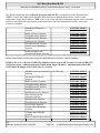
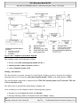
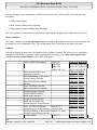
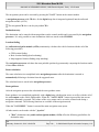
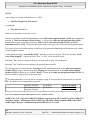
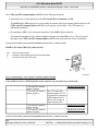
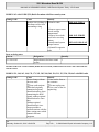
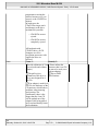
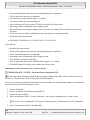
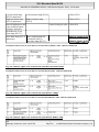
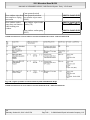
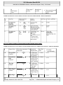
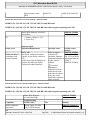
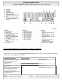
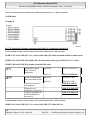
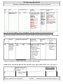
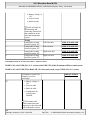
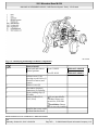
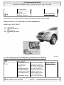
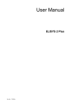
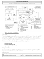
Fig. 83: MCS System Block Diagram
MCS system
The radio and navigation unit (A2/56) is the central component of the MCS system . It has a video-capable 5"
active matrix TFT display for indicating information such as control menus and map data for navigation.
Actuation is accomplished in operating modes NTSC (US standard) PAL (ECE standard). It is operated with
fixed function keys and a rotary knob, a joystick as well as with menu-guidance on the display.
The basic version of the radio and navigation unit (A2/56) is equipped with
a radio reception unit,
a compact cassette player and
a speed-dependent volume control.
Diagnostic interface
To read out actual values and DTC's of the MCS and components connected via the digital data bus ( D2B )
diagnosis with the hand-held tester is possible via a K-line.
MCS bus system
me
Saturday, October 02, 2010 3:30:06 PM
Page 131
© 2006 Mitchell Repair Information Company, LLC.
2001 Mercedes-Benz ML320
1998-2005 ACCESSORIES & BODY, CAB Electrical System - Body - 163 Chassis
The digital components of the radio and navigation unit (A2/56) are interlinked via the digital data bus
( D2B ). Control data, audio signals and other information are transmitted between the various system
components via the digital data bus ( D2B ) Since some of the individual components operate with various data
formats or place different requirements on the transmission speed and transmission security, various bus
systems are installed.
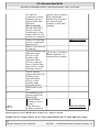
Switch on/off behavior,
function
Radio operation, function
CD-player mode, function
Telephone mode, function
Cassette mode, function
Navigation mode, function
Volume/tone adjustments,
function
Radio/navigation unit
location/task/design/ function
GF82.85-P-2006GI
GF82.60-P-2001GI
GF82.60-P-2002GI
GF82.85-P-2007GI
GF82.85-P-2010GI
GF82.85-P-2012GI
GF82.60-P-2003GI
GF82.61-P-4109GI
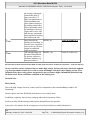
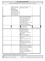
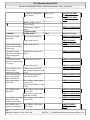
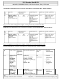
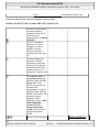
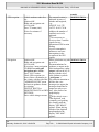
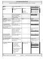
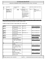
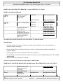
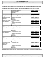
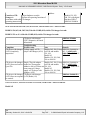
MODULAR CONTROL SYSTEM (MCS) FUNCTION DESCRIPTION CONTENTS - GF82.85-P-0995GIZ
MODEL 163 as of 1.9.01 with CODE (522) Modular control system (MCS) radio USA with CODE (357)
Navigation system - additional unit with CODE (818b) Single CD player - additional unit with CODE
(819) 6-disk CD changer with CODE (491) U.S. version
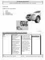
Modular control system (MCS), * for USA only
function
Switch on/off behavior,
function
Radio operation, function
CD-player mode, function
Telephone mode, function
Starguide, function
Information service, function
Data transmission for
Starguide, function
Cassette mode, function
Navigation mode, function
Voice output, function
Volume/tone adjustments,
function
Constant map matching,
function
Basic location finding, function
GF82.85-P-0011GI
GF82.85-P-2006GI
GF82.60-P-2001GI
GF82.60-P-2002GI
GF82.85-P-2007GI
GF82.85-P-2014GI
GF82.85-P-3016GI
GF82.85-P-3017GI
GF82.85-P-2010GI
GF82.85-P-2012GI
GF82.85-P-3001GI
GF82.60-P-2003GI
GF82.61-P-2002GI
GF82.61-P-3006GI
me
Saturday, October 02, 2010 3:30:06 PM
Page 132
© 2006 Mitchell Repair Information Company, LLC.
2001 Mercedes-Benz ML320
1998-2005 ACCESSORIES & BODY, CAB Electrical System - Body - 163 Chassis
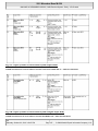
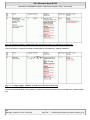
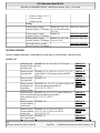
Global positioning system
location finding, function
Map-supported location
finding, function
Route calculation, function
Dynamic route guidance,
function
Guidance, function
Destination guidance in
digitized map area, function
Destination guidance in nondigitized map area, function
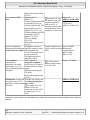
Modular control system (MCS)
survey of system components
location/task/design/ function
GF82.61-P-3007GI
GF82.61-P-3008GI
GF82.61-P-3011GI
GF82.61-P-4003GI
GF82.61-P-3012GI
GF82.61-P-4000GI
GF82.61-P-4001GI
GF82.85-P-9995GIZ
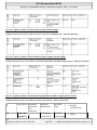
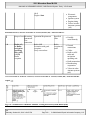
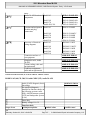
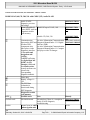
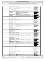
CONTENTS, FUNCTION DESCRIPTION OF COCKPIT MANAGEMENT AND DATA SYSTEM (COMAND) - GF82.85-P0997GHZ
MODEL 163
Cockpit management and data system
(COMAND) function
Switch-on/switch-off characteristics,
function
Radio operation, function
CD-player mode, function
Volume/tone adjustments, function
Navigation mode, function
Constant map matching, function
Basic location finding, function
Global positioning system location
finding, function
Map-supported location finding,
function
Route computation, function
Destination-finding system, function
Destination finding in digitized map
area, function
Destination finding in non-digitized
map area, function
Dynamic destination finding, function With dynamic
destination finding
(code 815) not for
GF82.85-P-0003GH
GF82.85-P-2006GH
GF82.60-P-2001GH
GF82.60-P-2002GH
GF82.60-P-2003GH
GF82.85-P-2012GH
GF82.61-P-2002GH
GF82.61-P-3006GH
GF82.61-P-3007GH
GF82.61-P-3008GH
GF82.61-P-3011GH
GF82.61-P-3012GH
GF82.61-P-4000GH
GF82.61-P-4001GH
GF82.61-P-4003GH
me
Saturday, October 02, 2010 3:30:06 PM
Page 133
© 2006 Mitchell Repair Information Company, LLC.
2001 Mercedes-Benz ML320
1998-2005 ACCESSORIES & BODY, CAB Electrical System - Body - 163 Chassis
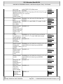
CTEL mode, function
For MB CTEL
GF82.85-P-2007GH
standard (code 853)
or MB portable
CTEL (code 854).
Voice command, function
GF82.85-P-3001GH
Table of contents, function description
GF82.62-P-0999B
of antenna system (ATS)
Overview of system components for
GF82.85-Pcockpit management and data system
9997GHZ
(COMAND ),
location/task/design/function
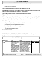
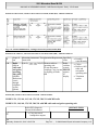
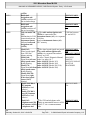
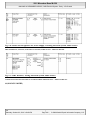
SWITCH ON/OFF BEHAVIOR, FUNCTION - GF82.85-P-2006B
MODEL 163, 168, 170, 203.0 /2 /7, 208, 209.3 /4, 210 with CODE (353) Audio 30 APS
ON/off characteristics
The radio (A2) is switched on by pressing the "ON" button. The radio (A2) likewise switches On automatically
by rotating the ignition key (models 163, 168, 170, 208, 210) or transmitter key (A8/1) (models 203, 209) into
position 1 "circuit 15R ON", provided that it was switched on immediately before the last time "circuit 15R
ON" was switched off. However, if the radio (A2) was switched off last, only the following components are
activated with "circuit 15R ON":
Digital databus (D2B)
Continuous location finding
In this case the display on the radio (A2) remains Off. This allows quick availability of the system when the
"ON" button is then actuated.
Following each switch-on operation, the system returns to the state in which it was before it was last switched
off (e.g. navigation basic menu).
The bus systems and navigation processor for location finding (for quicker readiness for operation) are
already activated when the driver door is opened.
Switch off characteristics
The system is switched off by switching off at the "ON" button or when "circuit 15R ON" is switched off.
The unit switches off automatically after an hour, if when switching on the ignition key (models 163, 168, 170,
208, 210) or transmitter key (A8/1) (models 203, 209) has not been inserted in the ignition switch.
Run-on time/navigation
me
Saturday, October 02, 2010 3:30:06 PM
Page 134
© 2006 Mitchell Repair Information Company, LLC.
2001 Mercedes-Benz ML320
1998-2005 ACCESSORIES & BODY, CAB Electrical System - Body - 163 Chassis
The data on the current navigation are stored for 12 hours after the radio (A2) is switched off.
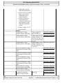
Radio operation, function
CD-player mode,
function
Telephone mode,
Model 209
function
Navigation mode,
Model 163, 168,
function
170,208,210
Model 203, 209
GF82.60-P-2001B
GF82.60-P-2002B
GF82.85-P-2007QA
GF82.85-P-2012B
GF82.85-P-2012EE
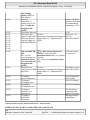
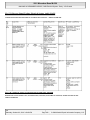
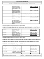
SWITCH-ON/OFF CHARACTERISTICS, FUNCTION - GF82.85-P-2006GI
MODEL 163 as of 1.9.01 with CODE (522) Modular control system (MCS) radio USA with CODE (357)
Navigation system - additional unit with CODE (818b) Single CD player - additional unit with CODE
(491) U.S. version
Switch-on characteristics
Activation of entire system
When the ignition/starter switch is turned to position 1(c.15R, ON ) the display is switched on , if the radio
and navigation module (A2/56) has been switched on before the ignition key was removed the last time.
The radio and navigation module (A2/56) is now ready for operation. The system active before the last
switch-off (e.g. radio) is switched on and the corresponding basic menu displayed. If the radio and navigation
module (A2/56) has been switched off for longer than 60 min a warning display appears with general
specifications for using the system.
When a telephone call is received the radio and navigation module (A2/56) switches on automatically.
Behavior when rotary knob is pressed
The radio and navigation module (A2/56) can also be switched on the when the remote control key (A8/1) is
removed by actuating the rotary knob.
All functions are then available for 60 min . After expiration of 60 min the radio and navigation module
(A2/56) switches off automatically.
This function can only be repeated by actuating the rotary knob again.
Switch-off characteristics
The radio and navigation module (A2/56) can be switched off by turning the ignition key to position 0 c. 15C,
OFF ).
me
Saturday, October 02, 2010 3:30:06 PM
Page 135
© 2006 Mitchell Repair Information Company, LLC.
2001 Mercedes-Benz ML320
1998-2005 ACCESSORIES & BODY, CAB Electrical System - Body - 163 Chassis
When the rotary knob is actuated in the switched-on state the radio and navigation module (A2/56) can be
switched off.
Switch-off characteristics when voltage is too low
The central processor in the radio and navigation module (A2/56) permanently monitors the battery voltage.
Depending on the voltage value the system will act as follows:
The battery voltage less than 9.5 volts
If the battery voltage drops below 9.5 volts the radio and navigation module (A2/56) switches off
automatically.
If the system switches off and the voltage increases to greater than 9.5 volt the radio and navigation module
(A2/56) does not switch back on automatically.
If the system switches off it can be switched back on manually .
Radio mode, function
CD-player mode,
function
Telephone mode,
function
Cassette mode, function
Navigation mode,
function
GF82.60-P-2001GI
GF82.60-P-2002GI
GF82.85-P-2007GI
GF82.85-P-2010GI
GF82.85-P-2012GI
TELEPHONE MODE, FUNCTION - GF82.85-P-2007GI
MODEL 163 as of 1.9.01 with CODE (522) Modular control system (MCS) radio USA with CODE (357)
Navigation system - additional unit with CODE (818b) Single CD player - additional unit with CODE
(491) U.S. version
me
Saturday, October 02, 2010 3:30:06 PM
Page 136
© 2006 Mitchell Repair Information Company, LLC.
2001 Mercedes-Benz ML320
1998-2005 ACCESSORIES & BODY, CAB Electrical System - Body - 163 Chassis
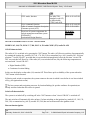
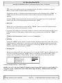
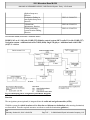
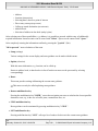
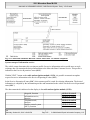
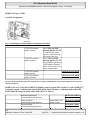
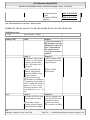
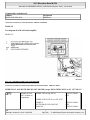
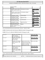
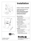
Fig. 84: MCS Telephone System Block Diagram
The telephone system can be operated as follows:
directly on the radio and navigation module (A2/56) or
with the portable cellular telephone (A34/6) or
with the telephone handset (A34)
Making a call, function
The data telegrams (e.g. button actuation) for controlling the telephone system are relayed to the telephone
transmitter/receiver (A35) from the radio and navigation module (A2/56) via the digital data bus ( D2B )
The actual telephone connection is completed by the CTEL/GPS antenna splitter (A2/57) and the CTEL and
GPS roof antenna (A2/49)
The audio source is automatically muted during a telephone call.
After switching over to the telephone mode the following display appears:
Strength of received signal (illustrated with 5 beams )
Message indicating readiness for telephone mode with "Ready " display.
me
Saturday, October 02, 2010 3:30:06 PM
Page 137
© 2006 Mitchell Repair Information Company, LLC.
2001 Mercedes-Benz ML320
1998-2005 ACCESSORIES & BODY, CAB Electrical System - Body - 163 Chassis
Multifunction keys "NUM " and "NAME ".
Entering code
The telephone can be protected against undesired use by entering a three - digit code. All telephone
functions are disabled except the emergency call function.
The telephone can be enabled again by entering the three - digit code (correction possible with " Clear " button
in the event of incorrect entry) and actuation of the multifunction key" OK ".
The following functions are available in the telephone mode:
Emergency call function
This function offers the possibility of transmitting an emergency call within the reception range of the
radio telephone network. The emergency call number is stored in the memory location 1 and can be
called even when the telephone is disabled. The emergency call is performed by pressing and holding
control button 1 down longer than 1 second " EMERGENCY " appears on the display. An emergency
call can be terminated by pressing " the "END " button.
Manual entry of telephone number
Telephone numbers can be entered manually on the number pad.
An incorrectly entered number can be deleted by momentarily pressing the " CLEAR " button. If the" CLEAR
" button is pressed for longer than 2 s all telephone numbers deleted
If the number entered consists of only 1 or 2 numbers, the telephone number stored in the memory with this
code is dialed.
The entered telephone number can be transmitted to the telephone by pressing the " SEND " button. The
telephone compares the transmitted telephone number with the telephone number stored in the memory. If the
numbers coincide the associated name, the memory location number and the telephone appear on the display
(depending on setting).
If the numbers do not coincide, the telephone number entered is still displayed.
Then the connection can be completed. The duration of the telephone call is indicated in minutes and seconds.
The call can be terminated by pressing the " END " button.
Selecting stored telephone number
The memory can be called up by pressing the multifunction key" NAME " or "NUM "."NAME "
indicates the stored names on the display" NUM " indicates the memory location number as well as the
associated telephone number. By pressing the" joystick " up or down the stored entries are displayed.
Pressing to the right or left causes display of the next 4 entries or previous 4 entries.
me
Saturday, October 02, 2010 3:30:06 PM
Page 138
© 2006 Mitchell Repair Information Company, LLC.
2001 Mercedes-Benz ML320
1998-2005 ACCESSORIES & BODY, CAB Electrical System - Body - 163 Chassis
If a name is not available for the stored telephone number, the display is switched over and the
memory location and the telephone number are displayed.
By manually entering 1 or 2 numbers and subsequent actuation of the multifunction key" NAME " or
"NUM " the name stored under this memory location number or the stored telephone number are
indicated.
Pressing " SEND " button completes the desired connection. If no connection is to be completed, the
memory area can be exited by pressing the multifunction key" EXIT ".
Quick dial
When a one or two-digit number is entered and the " SEND " button is actuated the telephone number
stored under this memory location number is dialed.
By pressing and holding one of the number buttons 1 to 9 for more than 2 s the telephone number stored
under this memory location number is dialed. In this case it is not necessary to actuate the " SEND "
button.
Memory location functions 1 number is reserved for emergency !
Redialing
Pressing the" SEND " button without previously entering a telephone number calls up the last 5 selected
telephone numbers on the display. It is possible to select the desired telephone number by pressing the"
joystick " up or down. The connection is completed by actuating the" SEND " button. This area can be
exited by pressing the multifunction key" EXIT ".
Incoming calls
During an incoming call all other audio sources are set to mute and "CALL " appears on the display. The
call can be accepted by pressing the " SEND " button or terminated by pressing the" END " button.
During a call it is possible to continue dialing, e.g. enter a code number for an answering machine.
GPS roof
antenna/telephone,
location/purpose/
design/function
GF82.70-P4111A
CASSETTE MODE, FUNCTION - GF82.85-P-2010GI
MODEL 163 as of 1.9.01 with CODE (522) Modular control system (MCS) radio USA with CODE (357)
Navigation system - additional unit with CODE (818b) Single CD player - additional unit with CODE
(491) U.S. version
me
Saturday, October 02, 2010 3:30:06 PM
Page 139
© 2006 Mitchell Repair Information Company, LLC.
2001 Mercedes-Benz ML320
1998-2005 ACCESSORIES & BODY, CAB Electrical System - Body - 163 Chassis
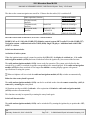
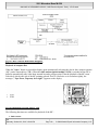
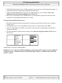
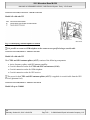
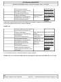
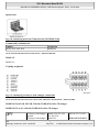
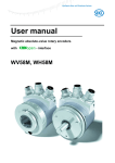
Fig. 85: MCS Cassette Mode Block Diagram
Playback of compact discs
When the" Open " button is pressed the display opens automatically releasing the slot for the c ompact cassettes
( CC ) and c ompact d iscs ( CD ). When the radio and navigation module (A2/56) is switched on the CC is
pulled in automatically after it has been inserted beyond a pressure point. Then the playback of the CC starts
with side 1 which is the side of the CC pointing upward. If a CC is defective or is wound too tightly, the
message (" Tape Error, Tape may be to tight ") appears on the display.
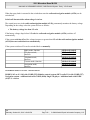
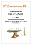
Fig. 86: Identifying CD Slot And CC Slot
The following functions are available for playback of the CC :
Auto reverse
me
Saturday, October 02, 2010 3:30:06 PM
Page 140
© 2006 Mitchell Repair Information Company, LLC.
2001 Mercedes-Benz ML320
1998-2005 ACCESSORIES & BODY, CAB Electrical System - Body - 163 Chassis
By pressing the multifunction key" Side " the side of the CC can be changed. This is indicated on the
display by" Side 1 " or" Side 2 ". The side changes automatically when the end of the tape is reached.
Fast forward/rewind
Pressing the "joystick " to the left right causes the CC to be wound backward and forward at high speed.
The procedure can be stopped by pressing the" joystick " again in any direction. When the end of the tape
is reached the side is changed automatically and playback continues.
Music search
The music search feature can be started by pressing the " joystick " upward for forward or downward for
rewind. During the search "MS FWD " or "MSREW " appears on the display. As soon as sufficiently
large pause ( approx. 3 s ) is recognized, the search stops and playback starts automatically. The search
can be stopped manually by pressing the" joystick " in any direction.
Scan function
The multifunction key" Scan " causes all titles on the CC to be played for approx. 8 s . . Pressing the
multifunction key" Scan " again stops this procedure.
Dolby B
Actuating multifunction key" Dolby " activates this function. The Dolby system appears inverted on the
display. Pressing again deactivates this function.
Pause "II"
The following events cause the function to change from "Play " to "Pause ":
Pressing multifunction key "Pause " (display changes from "II " to "Play ").
By an incoming or outgoing call
Switching over to another audio mode.
Pause recognition
Pressing the multifunction key" Skip " activates or deactivates the pause recognition function. If a pause
of more than 15 s . is recognized the drive changes automatically to fast forward. If this function is
activated the display appears inverted.
Volume/tone
adjustments, function
GF82.60-P-2003GI
NAVIGATION MODE, FUNCTION - GF82.85-P-2012B
MODEL 163, 168, 170, 208, 210 with CODE (353) Audio 30 APS
me
Saturday, October 02, 2010 3:30:06 PM
Page 141
© 2006 Mitchell Repair Information Company, LLC.
2001 Mercedes-Benz ML320
1998-2005 ACCESSORIES & BODY, CAB Electrical System - Body - 163 Chassis
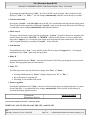
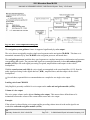
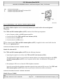
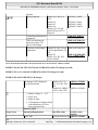
Audio 30 APS block diagram in navigation mode
Fig. 87: Audio 30 APS In Navigation Mode Block Diagram
The location of the vehicle as well as the direction and distance to the destination (according to destination
entered) is determined with the aid of the navigation system. Then the required measures to reach the
destination are started (guidance) .
The navigation system can be activated by pressing the "NAV" button on the radio and navigation unit
(A2/56) .
A navigation processor with CD-ROM drive is integrated into the radio and navigation unit (A2/56) for
reading in the navigation data (digital map, speech segments and software).
The navigation CD-ROM drive can also be used to play audio CDs.
Entering destination
The destination can be entered with menu guidance on the radio and navigation unit (A2/56) and processed by
the navigation processor . The system only allows entry of destination addresses stored on the CD-ROM.
The following possibilities are available for entering a destination:
Call-up of destination stored in destination memory
Free entry of destination with menu guidance based on name (when destination is stored on CD-ROM)
Location finding
me
Saturday, October 02, 2010 3:30:06 PM
Page 142
© 2006 Mitchell Repair Information Company, LLC.
2001 Mercedes-Benz ML320
1998-2005 ACCESSORIES & BODY, CAB Electrical System - Body - 163 Chassis
The navigation processor continuously calculates the location of the vehicle with the aid of the following
procedures:
GPS location finding
Basic location finding (dead reckoning)
Map-supported location finding (map matching)
The correct position is determined by continuously comparing the locating result of these three procedures.
Route calculation
The route is calculated in the navigation processor according to the destination entered, or automatically, after
deviating from the recommended route. The recommended route is stored in the navigation processor
Guidance
After the navigation processor has calculated the route, guidance is started. The driver receives continuous
information with the aid of guidance symbols appearing on the display of the radio and navigation unit
(A2/56) and voice announcements on the vehicle loudspeaker.
Audio 30 APS block diagram
Basic location finding (dead
reckoning), function
Global positioning system (GPS)
location finding, function
Map-assisted location finding,
function
Route calculation, function
Destination guidance, function
Loading language, function
Volume and tone settings
Radio mode, function
CD player mode, function
Radio and navigation unit,
location/purpose/ design/function
CTEL and GPS roof antenna,
location/purpose/ design/function
Global positioning system antenna,
location/ purpose/design/function
Antenna splitter,
Model 163
Model 168
Model 170
Models 208, 210
GF82.61-P-0002-02D
GF82.61-P-0002-02B
GF82.61-P-0002-02A
GF82.61-P-0002-02C
GF82.61-P-3006D
GF82.61-P-3007C
GF82.61-P-3008C
GF82.61-P-3011E
GF82.61-P-3012D
GF82.61-P-3003B
GF82.60-P-2003A
GF82.60-P-2001B
GF82.60-P-2002B
GF82.61-P-4109A
Models 163,
168,208.3,210
Models 170, 208.4
GF82.70-P-4111A
Model 163
GF82.85-P-3107B
GF82.61-P-4106A
me
Saturday, October 02, 2010 3:30:06 PM
Page 143
© 2006 Mitchell Repair Information Company, LLC.
2001 Mercedes-Benz ML320
1998-2005 ACCESSORIES & BODY, CAB Electrical System - Body - 163 Chassis
location/purpose/design/ function
NAVIGATION MODE, FUNCTION - GF82.85-P-2012GH
MODEL 163
Fig. 88: COMAND Navigation System Block Diagram
Function
The navigation system is integrated into the COMAND operating, display and control module (A40/3) . The
location of the vehicle and the direction to and distance from the destination (according to specified
destination) are determined with the aid of this system. Afterwards the required measures for reaching the
destination are initiated (destination finding) .
The navigation system is activated by pressing the " NAVI " button on the operating unit.
A navigation processor with CD drive for the digital map data is integrated in the COMAND operating,
display and control module (A40/3) .
The navigation CD drive can also play audio CDs .
me
Saturday, October 02, 2010 3:30:06 PM
Page 144
© 2006 Mitchell Repair Information Company, LLC.
2001 Mercedes-Benz ML320
1998-2005 ACCESSORIES & BODY, CAB Electrical System - Body - 163 Chassis
Note in Navi-CD screen :
"Please insert Navi-CD type DX "
Destination entry
Destination input is performed menu-guided on the operating unit and processed by the navigation processor .
Only destinations that are also on the CD-ROM may be entered. The COMAND operating, display and
control module (A40/3) provides the following destination input capabilities:
Address...
Destination memory...
Destination using map...
Special destinations (e.g. railway station, airport etc.)
Travel guide...
Intermediate destination entry
Destination memory with individual destination designation capabilities
Final destination...
Dynamic route calculation by:
Blocking of route sections (traffic-jam function)
Traffic-jam ahead
Blocking in route list
Incorporation of traffic information of an external service provider via telephone TCS (once, cyclic every
t=15min. ). Chargeable services.
Incorporation of traffic information via RDS broadcast (TMC ), free of charge
Predictive speller (editor)
During the entry of the destination the missing letters are augmented for an available list. This is only active in
the political index and relates to the destination and road entry as part of the destination finding. In the menu
Special destinations the submenus" Bypassing other locations... " and "National destinations... "are assisted.
The "Supraregional destination... " menu is divided up into additional submenues. The individual menu
points in this submenu use the political index .
Dynamic addition
implemented during manual entry of the destination. During the entry of the destination the missing letters are
augmented for an available list. The added letters are highlighted in black. Deleting is done one character at a
time.
Position finding
me
Saturday, October 02, 2010 3:30:06 PM
Page 145
© 2006 Mitchell Repair Information Company, LLC.
2001 Mercedes-Benz ML320
1998-2005 ACCESSORIES & BODY, CAB Electrical System - Body - 163 Chassis
COMAND continuously calculates the location of the vehicle with the aid of the following procedures:
GPS position finding
Basic position finding (compound position finding)
Map-supported position finding (map matching)
The navigation computer calculates the most probable position by continuously comparing the positionfinding results returned by these three methods.
Route calculation
The route is calculated by the navigation processor after entering the destination, or automatically, after a
deviation from the suggested route has taken place.
In the dynamic destination-finding system the route calculation is automatically influenced by the
incorporation of traffic information, free of charge via RDS, TMC or over an external provider TCS by
telephone (chargeable).
The calculated route is stored in the navigation processor .
Destination-finding system
Destination finding is started once the navigation computer has performed the destination calculation.
Three display options are available for graphical representation of the destination-finding system:
1. with map
2. with map and symbol display before turn-off point
--> MIX mode
3. with symbol display only (route guidance symbols)
Any of the three methods can be used. The destination-finding system is also supported by voice output from
the vehicle loudspeakers.
Route computation,
function
Constant map matching,
function
Basic location finding,
function
Destination-finding
system, function
Destination finding in
GF82.61-P-3011GH
GF82.61-P-2002GH
GF82.61-P-3006GH
GF82.61-P-3012GH
GF82.61-P-4000GH
me
Saturday, October 02, 2010 3:30:06 PM
Page 146
© 2006 Mitchell Repair Information Company, LLC.
2001 Mercedes-Benz ML320
1998-2005 ACCESSORIES & BODY, CAB Electrical System - Body - 163 Chassis
digitized map area,
function
Destination finding in
non-digitized map area,
function
Volume/tone
adjustments, function
Global positioning
system location finding,
function
GF82.61-P-4001GH
GF82.60-P-2003GH
GF82.61-P-3007GH
NAVIGATION MODE, FUNCTION - GF82.85-P-2012GI
MODEL 163 as of 1.9.01 with CODE (522) Modular control system (MCS) radio USA with CODE (357)
Navigation system - additional unit with CODE (818b) Single CD player - additional unit with CODE
(491) U.S. version
Fig. 89: Identifying MCS Navigation System Block Diagram
Function
The navigation system (optional) is integrated into the radio and navigation module (A2/56) .
With this system the vehicle location and the direction and distance to destination (after entering destination)
are determined. Then the required measures are taken to reach the destination (guidance ) .
me
Saturday, October 02, 2010 3:30:06 PM
Page 147
© 2006 Mitchell Repair Information Company, LLC.
2001 Mercedes-Benz ML320
1998-2005 ACCESSORIES & BODY, CAB Electrical System - Body - 163 Chassis
The navigation system can be activated by pressing the" NAVI " button on the control module.
A navigation processor with CD drive for the digital map data is integrated (optional) into the radio and
navigation module (A2/56)
The navigation CD drive can also play audio CD's .
Destination entry
The destination can be entered with menu-guidance on the control module and is processed by the navigation
processor . It is only possible to enter destinations which are stored on the CD-ROM .
Location finding
the radio and navigation module (A2/56) continuously calculates the vehicle location with the aid of the
following procedures:
GPS location finding
Basic location finding (dead reckoning)
Map-supported location finding (map matching)
The navigation processor calculates the most probable position by permanently comparing the location results
of these three methods.
Route calculation
The route calculation is accomplished in the navigation processor after the destination is entered or
automatically following a deviation from the suggested route.
The calculated route is stored in the navigation processor .
Route guidance
After the navigation processor has calculated the route guidance starts.
Route guidance is accomplished graphically with a digital map with direction arrows as well as with the aid of
the voice output on the vehicle loudspeakers. When the " NAVI VOICE " button is pressed the last current
navigation command is repeated. The volume of the voice output can be set on the volume knob during a
navigation command. The following functions are available in the navigation mode:
When the" NAVI MENU " button is actuated the main navigation menu opens.
All other entries can be made with the " joystick ".
"Dest" (destination entry)radio and navigation module (A2/56) offers the following possibilities for
destination entry:
me
Saturday, October 02, 2010 3:30:06 PM
Page 148
© 2006 Mitchell Repair Information Company, LLC.
2001 Mercedes-Benz ML320
1998-2005 ACCESSORIES & BODY, CAB Electrical System - Body - 163 Chassis
Address
Junction (intersection)
Selecting hotel, church or point of interest
Direct entry on map (map cursor)
Calling up stored destination (recent route)
Address book
Selection of address in date book (today's plan)
After selecting one of these possibilities, e.g. address, it is possible to proceed with the entry of additionally
required information. Incorrect entries can be erased with " Delete " Spaces can be entered with " Space ".
After completely entering the information confirm by pressing the "joystick " (Ent).
"OK to proceed " starts calculation of the route.
Setup (settings)
Various settings for the screen display and route guidance can be made with this menu.
Option (selection)
With this menu information, e.g. location, can be called up.
Entries in address book, in date book or in list of last driven routes can be processed by selecting
correspondingly.
Route
This menu provides settings influencing the current route guidance.
This menu can only be called up during route guidance.
Detour multifunction key
Pressing the multifunction key" DETR " causes the navigation processor to calculate the closest possible
alternative route, e.g. in the case of traffic jams, constructions sites, etc.
STOP multifunction key
Route guidance can be terminated by pressing multifunction key" STOP ".
LIST multifunction key
Pressing multifunction key" LIST " calls up a list of roads to be driven in the current route guidance.
me
Saturday, October 02, 2010 3:30:06 PM
Page 149
© 2006 Mitchell Repair Information Company, LLC.
2001 Mercedes-Benz ML320
1998-2005 ACCESSORIES & BODY, CAB Electrical System - Body - 163 Chassis
MUTE multifunction key
Muting voice output.
MAP multifunction key
Changing between map display and direction arrow display
Pressing the "Clear " key returns to the previous menu.
Constant map
matching,
function
Route
calculation,
function
Guidance,
function
Voice output,
function
Volume/tone
adjustments,
function
GF82.61-P2002GI
GF82.61-P3011GI
GF82.61-P3012GI
GF82.85-P3001GI
GF82.60-P2003GI
STARGUIDE, FUNCTION - GF82.85-P-2014GI
MODEL 163 as of 1.9.01 with CODE (522) Modular control system (MCS) radio USA with CODE (357)
Navigation system - additional unit with CODE (818b) Single CD player - additional unit with CODE
(491) U.S. version
The StarGuide system uses the availability of the present technologies for telecommunications.
These are used for the purpose of personal information services.
The service "Dynamic route guidance " will be added to the system at a later time.
Technical requirements:
E-Call and
MCS and
newest navigation CD (it includes the current software for executing the offered services). The MCS is
updated with this and
the prerequisites required for executing the corresponding systems are fulfilled.
Organizational prerequisites:
me
Saturday, October 02, 2010 3:30:06 PM
Page 150
© 2006 Mitchell Repair Information Company, LLC.
2001 Mercedes-Benz ML320
1998-2005 ACCESSORIES & BODY, CAB Electrical System - Body - 163 Chassis
GPS G lobal P ositioning S ystem. Satellite-supported system for precise positioning and navigation. At
present 26 satellites are in operation orbiting the earth on 6 orbits.
AMPS: A dvanced M obile P hone S ystem. The AMPS network is now available to 98% of the
population in the most densely-populated areas of the USA .
SOC: S ervice O perating Center. The SOC takes over all individual requirements of the driver and
transmits the corresponding information to the vehicle.
Concept of personal information service:
Individual information and news transmission according to personal interest profile (stock exchange,
weather, sport...)
Transmitting a request via a button (SVC button) to the S ervice O perating C enter (SOC )
e S ervice O perating C enter (SOC ) transmits the customer profile corresponding to the individual
information and news.
The data transmitted is indicated on the display of the radio and navigation module (A2/56) and can
then be read.
Information
service,
function
Data
transmission
for Starguide,
function
GF82.85-P3016GI
GF82.85-P3017GI
VOICE OUTPUT, FUNCTION - GF82.85-P-3001GI
MODEL 163 as of 1.9.01 with CODE (522) Modular control system (MCS) radio USA with CODE (357)
Navigation system - additional unit with CODE (818b) Single CD player - additional unit with CODE
(491) U.S. version
me
Saturday, October 02, 2010 3:30:06 PM
Page 151
© 2006 Mitchell Repair Information Company, LLC.
2001 Mercedes-Benz ML320
1998-2005 ACCESSORIES & BODY, CAB Electrical System - Body - 163 Chassis
Fig. 90: MCS Voice Output Block Diagram
The navigation system guidance feature is supported significantly by voice output .
The voice data was originally stored as single-word segments on the navigation CD-ROM . This data set is
transmitted automatically by the CD-ROM to the navigation processor and stored there.
The navigation processor interlinks these word segments to complete instructions or information and generates
corresponding AF signals. The generated AF signals are transmitted internally in the radio and navigation
module (A2/56) to the audio signal processing if required, amplified there and output via the vehicle
loudspeakers.
With the sound system (code 810) the voice signals are transmitted to the sound amplifier (A2/13) from the
audio signal processing via the digital data bus ( D2B ), amplified there, and then output via the vehicle
loudspeakers.
Several short, sequential drive recommendations are compiled to one single voice output.
Loading voice from CD-ROM
Only English is presently available for voice output on the radio and navigation module (A2/56) .
Volume of voice output
The voice output volume can be adjusted during voice output . This ensures that a defined interval is
maintained between the volume of the current audio source and voice output.
Example:
If the volume is reduced during voice output and the preceding volume interval to the audio signal is not
reached the radio and navigation module (A2/56)
me
Saturday, October 02, 2010 3:30:06 PM
Page 152
© 2006 Mitchell Repair Information Company, LLC.
2001 Mercedes-Benz ML320
1998-2005 ACCESSORIES & BODY, CAB Electrical System - Body - 163 Chassis
reduces the level of the audio signal until the specified volume interval is reached again. The volume of the
audio signal is then again increased after completion of the voice output to the level present before the voice
output.
Moreover, the volume of the voice output cannot be reduced below a certain minimum level .
Voice output mute circuit
Navigation voice output can be muted by actuating the mute multifunction key. Muting remains active until the
mute multifunction key is pressed again.
Navigation mode, function
Radio and navigation
module, location/purpose/
design/function
GF82.85-P-2012GI
GF82.61-P-4109GI
INFORMATION SERVICE, FUNCTION - GF82.85-P-3016GI
MODEL 163 as of 1.9.01 with CODE (522) Modular control system (MCS) radio USA with CODE (357)
Navigation system - additional unit with CODE (818b) Single CD player - additional unit with CODE
(491) U.S. version
Fig. 91: Service Request Display Using SVC Button (Example)
Service request procedure
It is possible to change to the service mode with the button " SVC " on the radio and navigation module
me
Saturday, October 02, 2010 3:30:06 PM
Page 153
© 2006 Mitchell Repair Information Company, LLC.
2001 Mercedes-Benz ML320
1998-2005 ACCESSORIES & BODY, CAB Electrical System - Body - 163 Chassis
(A2/56) .
A new request is selected in the basic screen " SVC ":
"Send New Request for Info Service "
or optionally:
"View Info Service of..."
allows a previous data record to be viewed.
Selection is possible with the knob/pushbutton on the radio and navigation module (A2/56) and confirmed by
pressing. If" Send New Request for Info Service " is selected, the radio and navigation module (A2/56)
transmits this request via the digital data bus ( D2B ) to the E-call control module (A35/8) and CTEL
transmitter/receiver (A35) . It transmits the request to the service provider via the present telephone network.
The request is processed on the Internet on the basis of the personal information profile and sent to the vehicle
via the telephone network.
A tone and the message:" New Info Received! " indicates reception to the user. The safety question:" Read
Later When Stopped? " with the decision " Yes " or "No " serves for traffic safety.
Selecting:" Yes " leads to a return to the previous menu such as radio, CD, navigation......
Selecting:" No " lists the news according to the personal interest profile.
The messages can be read in sequence. Pressing the knob/ pushbutton button on the radio and navigation
module (A2/56) jumps to the next news item. Turning the knob/pushbutton on the radio and navigation
module (A2/56) scrolls the news. With the" BACK " button on the radio and navigation module (A2/56) it is
always possible to jump back to the previous menu.
The information that is received can be read page by page. It is not possible to jump directly to a certain
page. The format can be changed by the operator.
Starguide, function
Data transmission for
Starguide, function
As of 09/00
As of 09/00
GF82.85-P-2014GI
GF82.85-P-3017GI
DATA TRANSMISSION FOR STARGUIDE, FUNCTION - GF82.85-P-3017GI
MODEL 163 as of 1.9.01 with CODE (522) Modular control system (MCS) radio USA with CODE (357)
Navigation system - additional unit with CODE (316) MB GSM cellular telephone (D2B) with CODE
(818b) Single CD player - additional unit with CODE (491) U.S. version
me
Saturday, October 02, 2010 3:30:06 PM
Page 154
© 2006 Mitchell Repair Information Company, LLC.
2001 Mercedes-Benz ML320
1998-2005 ACCESSORIES & BODY, CAB Electrical System - Body - 163 Chassis
Fig. 92: Connection Schematic Between Vehicle And Center Via Mobile Telephone
System concept of information service:
The vehicle owner determines his own interest profile for service information such as world news or stock
exchange data. He transmits the desired information to the Mercedes Benz Customer Service. This profile is
indicated to the S ervice O peration Center (SOC ).
With the" SVC " button on the radio and navigation module (A2/56) it is possible to transmit an update
request for service information to the S ervice O perating C enter (SOC ).
In the S ervice O peration C enter (SOC ) this customer profile is used for selecting information. The desired
information is compiled by the information provider and transmitted to the vehicle via the S ervice O peration C
enter (SOC ).
The data transmitted is indicated on the display in the radio and navigation module (A2/56) .
Starguide, function
Information service,
function
Telephone mode,
function
Modular control system
(MCS), function
GF82.85-P-2014GI
GF82.85-P-3016GI
GF82.85-P-2007GI
GF82.85-P-0011GI
me
Saturday, October 02, 2010 3:30:06 PM
Page 155
© 2006 Mitchell Repair Information Company, LLC.
2001 Mercedes-Benz ML320
1998-2005 ACCESSORIES & BODY, CAB Electrical System - Body - 163 Chassis
ANTENNA SPLITTER, LOCATION - GF82.85-P-3107-01B
Model 163 with code 353
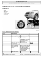
Fig. 93: Identifying Antenna Splitter Location
It is possible to connect a GSM telephone to the connector not specified using a coaxial cable.
ANTENNA SPLITTER, DESIGN - GF82.85-P-3107-03B
Model 163 with code 353
The CTEL and GPS antenna splitter (A2/57) consists of the following components:
Active frequency splitter with GPS antenna amplifier
Coaxial connection socket for CTEL and GPS roof antenna (A2/49)
Coaxial connection socket for GSM telephone
Coaxial connection socket for GPS receiver
The power for the CTEL and GPS antenna splitter (A2/57) is supplied via coaxial cable from the GPS
receiver (phantom feed).
ANTENNA SPLITTER, DESIGN - GF82.85-P-3107-03GH
Model 163 up to 31.08.01
me
Saturday, October 02, 2010 3:30:06 PM
Page 156
© 2006 Mitchell Repair Information Company, LLC.
2001 Mercedes-Benz ML320
1998-2005 ACCESSORIES & BODY, CAB Electrical System - Body - 163 Chassis
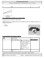
Fig. 94: Identifying CTEL And GPS Antenna Splitter Design
A GSM cellular telephone can be connected by means of a coaxial cable to the non-designated
connection.
The CTEL and GPS antenna splitter (A2/57) consists of the following components:
Active frequency splitter with GPS antenna amplifier
Coaxial socket for the CTEL and GPS roof antenna (A2/49)
Coaxial socket for a GSM CTEL
Coaxial socket for a GPS receiver
The voltage for the CTEL and GPS antenna splitter (A2/57) is supplied via the coaxial cable from the
GPS receiver ( phantom feed ).
ANTENNA SPLITTER, FUNCTION - GF82.85-P-3107-04B
Model 163 with code 353
The CTEL and GPS antenna splitter (A2/57) has the following functions:
Separating the signals received from the CTEL and GPS roof antenna (A2/49) :
The GSM and GPS signals are received by the antenna splitter via an antenna lead and leave the CTEL
and GPS antenna splitter (A2/57) via two separate coaxial cables. In addition the GPS signals are
amplified.
Decoupling the GPS receiver from the GSM telephone transmitter:
It must be ensured that the telephone transmitter signals do not reach the GPS receiver. The CTEL and
GPS antenna splitter (A2/57) allows them to pass only in the direction of the roof antenna.
ANTENNA SPLITTER, FUNCTION - GF82.85-P-3107-04GH
Model 163 up to 31.08.01
me
Saturday, October 02, 2010 3:30:06 PM
Page 157
© 2006 Mitchell Repair Information Company, LLC.
2001 Mercedes-Benz ML320
1998-2005 ACCESSORIES & BODY, CAB Electrical System - Body - 163 Chassis
The CTEL and GPS antenna splitter (A2/57) has the following functions:
Separating the receiving signals from the CTEL and GPS roof antenna (A2/49) :
The GSM and the GPS signals are received along an antenna cable at the antenna splitter and leave the
CTEL and GPS antenna splitter (A2/57) in two separate coaxial cables. The GPS signals are
additionally amplified.
Decoupling the GPS receiver from the transmitter of the GSM cellular telephone:
The transmission signals of the cellular telephone must not reach the GPS receiver. They are passed
through by the CTEL and GPS antenna splitter (A2/57) only in the direction of the roof antenna.
ANTENNA SPLITTER, LOCATION/PURPOSE/DESIGN/FUNCTION - GF82.85-P-3107B
MODEL 163 with CODE (353) Audio 30 APS
Fig. 95: Identifying CTEL And GPS Antenna Splitter Design
It is possible to connect a GSM telephone to the connector not specified using coaxial cable.
CTEL and GPS antenna
splitter, location
CTEL and GPS antenna
splitter, purpose
GF82.85-P-3107-01B
The CTEL and GPS
antenna splitter (A2/57)
is required for operating a
GSM telephone and a
GPS receiver with one
single antenna cable.
CTEL and GPS antenna
splitter, design
CTEL and GPS antenna
splitter, function
GF82.85-P-3107-03B
GF82.85-P-3107-04B
ANTENNA SPLITTER, LOCATION/PURPOSE/DESIGN/FUNCTION - GF82.85-P-3107GH
me
Saturday, October 02, 2010 3:30:06 PM
Page 158
© 2006 Mitchell Repair Information Company, LLC.
2001 Mercedes-Benz ML320
1998-2005 ACCESSORIES & BODY, CAB Electrical System - Body - 163 Chassis
MODEL 163 up to 31.8.01
Location of component
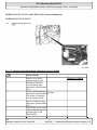
Fig. 96: Identifying Antenna Splitter Components Location
CTEL/GPS antenna
splitter, location
CTEL/GPS antenna
splitter, purpose
The CTEL and GPS
antenna splitter (A2/57)
is located in the center
console on the left-hand
side in the radio slot.
The CTEL and GPS
antenna splitter (A2/57)
is required for operating a
GSM cellular telephone
and a GPS receiver over a
single antenna cable.
CTEL/GPS antenna
splitter, design
CTEL/GPS antenna
splitter, function
GF82.85-P-3107-03GH
GF82.85-P-3107-04GH
MODULAR CONTROL SYSTEM (MCS) SURVEY OF SYSTEM COMPONENTS LOCATION/TASK/DESIGN/FUNCTION GF82.85-P-9995GIZ
MODEL 163 as of 1.9.01 with CODE (522) Modular control system (MCS) radio USA with CODE (357)
Navigation system - additional unit with CODE (818b) Single CD player - additional unit with CODE
(819) 6-disk CD changer in trunk with CODE (491) U.S. version
Radio/navigation unit
location/task/design/ function
Sound amplifier
location/task/design/function
Antenna splitter,
location/task/design/function
GF82.61-P-4109GI
with CODE (810)
Sound system
GF82.62-P-3100GH
GF82.85-P-3107B
me
Saturday, October 02, 2010 3:30:06 PM
Page 159
© 2006 Mitchell Repair Information Company, LLC.
2001 Mercedes-Benz ML320
1998-2005 ACCESSORIES & BODY, CAB Electrical System - Body - 163 Chassis
FM/AM antenna amplifier,
location/purpose/ design/function
GPS/CTEL roof antenna
location/task/design/ function
CD player with changer,
location/purpose/ design/function
Modular control system (MCS)
function description contents
GF82.62-P-4101A
GF82.70-P-4111A
With CD changer
(code 819)
GF82.64-P-3113GI
GF82.85-P0995GIZ
OVERVIEW OF SYSTEM COMPONENTS FOR COCKPIT MANAGEMENT AND DATA SYSTEM (COMAND ),
LOCATION/TASK/DESIGN/FUNCTION - GF82.85-P-9997GHZ
MODEL 163
Operating, display and control module,
location/ purpose/design/function
CD player with changer,
location/purpose/ design/function
Sound amplifier,
location/task/design/function
FM/AM antenna amplifier,
location/purpose/ design/function
GPS/telephone roof antenna,
location/task/ design/function
Antenna splitter,
location/task/design/function
Contents, function description of
cockpit management and data system
(COMAND)
GF82.85-P-3114GH
with (Code 819) CD
changer
with CODE (810)
sound system
MODELS 163, 168,
170, 208, 210
MODELS 163, 168,
208.3, 210
Model 163
GF82.64-P-3113GH
GF82.62-P-3100GH
GF82.62-P-4101A
GF82.70-P-4111A
GF82.85-P-3107B
GF82.85-P0997GHZ
E-CALL BACKUP ANTENNA, LOCATION/PURPOSE - GF82.95-P-4205GH
MODEL 163 as of 1.9.01 with CODE (349) E-Call emergency call system with CODE (491) U.S. version
me
Saturday, October 02, 2010 3:30:06 PM
Page 160
© 2006 Mitchell Repair Information Company, LLC.
2001 Mercedes-Benz ML320
1998-2005 ACCESSORIES & BODY, CAB Electrical System - Body - 163 Chassis
Fig. 97: Identifying E-Call Backup Antenna Location
E-Call backup antenna,
location
The EMERGENCY
CALL backup antenna
(A2/50) is mounted on the
inside of the rear bumper .
E-Call backup antenna,
purpose
Transmitting and
receiving the
EMERGENCY CALL
signals if reception via the
CTEL and GPS roof
antenna (A2/49) is poor.
SAFETY PRECAUTIONS
SAFETY INFORMATION: ELECTRICAL SYSTEM BODY - AS82.00-Z-9999ZZ
MODEL all
Risk of death caused by
high voltage at xenon
headlamps. Risk of
explosion/risk of fire
caused by highly
flammable materials in
MODEL all...
AS82.10-Z-0001-01A
me
Saturday, October 02, 2010 3:30:06 PM
Page 161
© 2006 Mitchell Repair Information Company, LLC.
2001 Mercedes-Benz ML320
1998-2005 ACCESSORIES & BODY, CAB Electrical System - Body - 163 Chassis
the vicinity of damaged
xenon bulbs. Risk of
injury caused by UV
light, hot components at
xenon headlamps and
glass splinters produced
by bursting xenon bulbs.
Risk of poisoning caused
by inhalation of mercury
vapors and by toxic salts
and mercury compounds
being ingested or coming
into contact with skin
Injury hazard from
MODEL all
pinching and crushing, in
extreme cases extremities
can even be cut off when
caught in windshield
wiper mechanism.
The demagnetizing coil MODEL 140...
presents a lethal hazard
for persons with active
electronic implants (e.g.
heart pacemakers).
AS82.30-Z-0001-01A
AS82.85-Z-0001-01A
RISK OF DEATH, RISK OF EXPLOSION/RISK OF FIRE, RISK OF INJURY & RISK OF POISONING - AS82.10-Z-0001-01A
Do not come into contact with parts that are under high voltage. Persons with active electronic implants
(e.g. heart pacemakers) must never work on xenon headlamps. Switch off entire lighting system. Wear
insulated safety shoes, safety glasses and protective gloves. Remove highly inflammable materials from
the hazard area. Ensure sufficient ventilation in the working area.
Potential risks
Risk of death
Due to the high voltages involved, contact with live components at the xenon headlamps could be life
threatening!
Electric shocks can cause fibrillation of the heart or even cardiac arrest.
In addition, respiratory muscles may cramp up and result in respiratory failure.
Serious, possibly life-threatening, brain function disruptions are also possible.
It may take a few minutes for the consequences of an electrical shock to manifest themselves.
me
Saturday, October 02, 2010 3:30:06 PM
Page 162
© 2006 Mitchell Repair Information Company, LLC.
2001 Mercedes-Benz ML320
1998-2005 ACCESSORIES & BODY, CAB Electrical System - Body - 163 Chassis
Risk of explosion/risk of fire
Highly flammable materials in the vicinity of damaged, energized xenon bulbs may result in explosion or cause
fires.
Risk of injury
UV light may escape when operating xenon bulbs not properly installed in the xenon headlamps. This UV light
may cause damage to the eyes (conjunctival infection) and to skin burns (sunburns) if skin is unprotected.
In both intact or faulty xenon headlamps, hot or glowing components may cause serious burn injuries if they
come into contact with unprotected skin or eyes.
Glass splinters produced by the destruction of xenon bulbs may cause cut injuries in unprotected skin and
unprotected eyes.
Risk of poisoning
When xenon bulbs are destroyed, serious health problems may be caused if the mercury vapors produced are
inhaled or if mercury compounds or toxic salts are ingested or absorbed through the skin. Possible
consequences include nausea, vomiting and gastrointestinal disruptions as well as degradation of the kidneys
and the central nervous system. Skin and eye damage may also result.
Safety precautions/instructions
Persons with electronic implants (e.g. pacemakers) must never work on xenon headlamps.
Wear safety shoes (with rubber soles).
Prior to working on xenon headlamps (e.g. replacing parts, hooking up test equipment, etc.), the complete
lighting system must be switched off and the xenon headlamps must be disconnected from the on-board
electrical system.
If the xenon headlamps are switched on, never touch components under high voltage.
If the xenon headlamps are switched on, maintain a clearance of at least 30 mm to components under high
voltage.
Avoid all contact with hot components.
Wait at least 3 min after switching off xenon bulbs before touching them.
Do not damage or destroy xenon bulbs.
Safety precautions/instructions
Never operate xenon bulbs unless they are properly installed in xenon headlamps with UV-absorbing
headlamp lenses.
Keep all highly flammable materials away from working area.
Wear suitable protective gloves and safety glasses.
Ensure that the workplace is sufficiently ventilated.
me
Saturday, October 02, 2010 3:30:06 PM
Page 163
© 2006 Mitchell Repair Information Company, LLC.
2001 Mercedes-Benz ML320
1998-2005 ACCESSORIES & BODY, CAB Electrical System - Body - 163 Chassis
First aid measures
Electrical shock
Switch off current, bring injured person to safety.
Immediately notify an emergency physician.
Perform mouth to mouth respiration, if necessary.
Perform cardiopulmonary resuscitation, if necessary.
Burn injuries
Cool affected skin area with cold water.
Cover burn wounds with sterile dressing.
Consult a physician.
Cut injuries/skin injuries
Stop the bleeding.
Dress cut/skin injury.
Consult a physician.
Foreign object in eye
Cover affected eye with a sterile dressing.
Cover both eyes to calm them.
Consult an eye doctor immediately.
Eye contact with mercury vapors/toxic salts
Flush eyes with lukewarm water.
Cover eye with sterile dressing.
Consult an eye doctor immediately.
Eye contact with UV light
Consult an eye doctor immediately.
Poisoning caused by inhaling mercury vapors
Take victim to fresh air.
Consult a physician immediately.
Poisoning caused by ingesting toxic salts or mercury compounds
me
Saturday, October 02, 2010 3:30:06 PM
Page 164
© 2006 Mitchell Repair Information Company, LLC.
2001 Mercedes-Benz ML320
1998-2005 ACCESSORIES & BODY, CAB Electrical System - Body - 163 Chassis
Consult a physician immediately.
Always consult a medical service or physician after administering first aid.
INJURY HAZARD FROM PINCHING AND CRUSHING, IN EXTREME CASES EXTREMITIES CAN EVEN BE CUT OFF
WHEN CAUGHT IN WINDSHIELD WIPER MECHANISM. - AS82.30-Z-0001-01A
Always remove ignition key before working on windshield wiper mechanism.
Injury hazard
When working in the area of the windshield wiper mechanism with the ignition key in position "1" or "2" the
wiper arm or wiper linkage can be pushed out of its end position and start running unintentionally . This can
result in severe injuries by cutting, pinching or crushing body parts.
Rules of behavior/protective measures
Always remove ignition key before working on windshield wiper mechanism.
Secure operating range of mechanism against reaching in.
Keep sufficient distance away from moving parts.
Supervise hazard area.
Wear tight fitting clothing and hair net.
TROUBLE DIAGNOSIS
HIGH BEAMS AND/OR LOW BEAMS DO NOT WORK - AF82.10-P-2009B
MODEL 129,140,163,170, 202, 208, 210, 215, 220 with CODE (612) Xenon headlamp unit
Modification notes
4.4.00
Damage code
Supersedes STIP 82.10019 from 24.03.2000
Cause
Remedy
Risk of death caused Do not come into contact with
AS82.10-Z-0001-01A
by high voltage levels parts that are under high voltage.
present at xenon
Persons with active electronic
headlamps.
implants (e.g. heart pacemakers)
Risk of explosion/risk must never work on xenon
of fire caused by highly headlamps. Switch off the
inflammable substances complete lighting system. Wear
at damaged xenon bulbs insulated safety shoes, safety
Risk of injury caused glasses and protective gloves.
by UV light, hot
Remove highly inflammable
components at xenon materials from the hazard area.
me
Saturday, October 02, 2010 3:30:06 PM
Page 165
© 2006 Mitchell Repair Information Company, LLC.
2001 Mercedes-Benz ML320
1998-2005 ACCESSORIES & BODY, CAB Electrical System - Body - 163 Chassis
82 119
headlamps and glass
Ensure that the working area is
splinters from broken sufficiently ventilated.
xenon bulbs
Risk of poisoning
caused by inhaling
mercury vapor and by
swallowing/skin contact
with toxic salts and
mercury compounds
We receive at the diagnostic
centers of the plants more and
more xenon control units and
xenon lamps which are o.k.
To avoid this high number of
problem parts with no
reproducible faults, we would ask
you to use the following
procedure for troubleshooting:
1 Perform diagnosis according to
instructions in WIS.
Model 202, 208, 210
AD82.10-P-1001AZ
If the fault cannot be
recognized or the faulty
component determined: ?
2 Interchange the xenon lamps
(right to left).
For the time being do not
replace system components.
If the fault of the xenon lamp
still exists: ?
3 Remove/install/replace xenon
lamp.
If the fault remains in the
headlamp the cause may be the
xenon control unit or a fault on
the vehicle side.
We are aware of the fact that
this procedure may possibly lead
to another stay in the workshop of
the vehicle in question.
However, we see no other
alternative if the redebiting of
warranty and goodwill costs is to
be avoided.
WINDSHIELD WASHER WATER RESERVOIR LEAKY - AF82.35-P-4043B
me
Saturday, October 02, 2010 3:30:06 PM
Page 166
© 2006 Mitchell Repair Information Company, LLC.
2001 Mercedes-Benz ML320
1998-2005 ACCESSORIES & BODY, CAB Electrical System - Body - 163 Chassis
MODEL 163.113/136/154/172 With 5 L reservoir
Damage code
Cause
Stress fracture in
windshield washer water
reservoir.
Remedy
1 Replace windshield
washer water reservoir
with large capacity
reservoir.
SM82.35-P-0002GH
INSTALLING SOUND SYSTEM JUMPER HARNESS - AF82.60-P-1010-01AG
1. Insert sound system jumper harness through radio opening
Position jumper harness within cockpit assembly so that jumper harness is routed above HVAC
venturi tube and lays across base of steering column.
2. Plug male radio harness connector A/B (1) into corresponding female connector (2) of jumper harness
3. Secure connectors, phone antenna and phone power lead with cable tie (3) next to radio harness mounting
clip on HVAC case
Fig. 98: Identifying Phone Power Lead With Cable Tie, Male Radio Connector And Corresponding
Female Connector
4. Attach jumper harness (4) to steering column mounting bracket with integrated harness clip (5) and clip
on female amplifier connector (6) of jumper harness
5. Secure jumper harness (4) to dash support bracket with cable tie (7)
Install cable tie on convolute tubing protected area of jumper harness.
me
Saturday, October 02, 2010 3:30:06 PM
Page 167
© 2006 Mitchell Repair Information Company, LLC.
2001 Mercedes-Benz ML320
1998-2005 ACCESSORIES & BODY, CAB Electrical System - Body - 163 Chassis
Fig. 99: Identifying Female Amplifier Connector, Cable Tie And Harness Clip
6. Cut slot in insulation to access sound system amplifier (A2/13) electrical connectors.
7. Disconnect male connector A/B (9) on sound system amplifier and plug into female amplifier connector
(6) of jumper harness
8. Plug male connector A/B (8) of jumper harness into corresponding connection on sound system amplifier
9. Refit insulation
Fig. 100: Identifying Sound System Amplifier, Plug Male Connector A/B And Integrated Harness
Clip
HUMMING SOUND FROM SPEAKERS WITH RADIO SET ON LOW VOLUME - AF82.60-P-1010AG
me
Saturday, October 02, 2010 3:30:06 PM
Page 168
© 2006 Mitchell Repair Information Company, LLC.
2001 Mercedes-Benz ML320
1998-2005 ACCESSORIES & BODY, CAB Electrical System - Body - 163 Chassis
MODEL 163 with CODE (259) Radio Premium with Bose sound system
Damage code
Parts ordering notes
Part no.
163 540 98 05
Cause
Remedy
Speaker wires picking up 1 Remove radio
interference noise from
surrounding wiring
2 Remove upper center
console storage
compartment
3 Remove lower dash
panel below steering
column
4 Install sound system
jumper harness
5 Reinstall in opposite
order
Designation
Jumper harness for Bose sound
system
AR82.60-P-7502EA
AR68.10-P-1500GH
AF82.60-P-1010-01AG
Quantity
1
PROGRAM CHANGE ALTHOUGH RDS [RADIO DATA SYSTEM] AND REGIONALIZATION ARE SWITCHED ON AF82.60-P-1062A
MODEL 129, 140, 163, 168, 170, 171, 202, 203, 208, 209, 210, 211, 215, 220, 230, 463 with RDS radio
Damage code
Cause
Station change without
obvious cause.
Some radio stations
which had originally
transmitted regional
identification have been
transmitting the RDS
signals without regional
identification for some
time.
Without regional
identification it is no
longer possible to
separate stations with the
same station name which
transmit different
programs.
Remedy
1 Point out the facts to
the customer.
Do not replace any
devices, state of the art
engineering.
me
Saturday, October 02, 2010 3:30:06 PM
Page 169
© 2006 Mitchell Repair Information Company, LLC.
2001 Mercedes-Benz ML320
1998-2005 ACCESSORIES & BODY, CAB Electrical System - Body - 163 Chassis
INTERMITTENT INTERRUPTIONS OF RADIO RECEPTION IN RDS MODE - AF82.60-P-1101A
MODELS 163,168,170, 208, 210 with CODE (756a) MB radio Audio 10 RDS with CD compartment
Damage code
Cause
Remedy
Under unfavorable
Due to the equipment
reception conditions in and antenna design there
FM-RDS mode, the radio is no remedy available.
may frequently switch to
alternative frequencies of
one and the same radio
station.
During switchover,
Do not replace any radios
reception may be
subject to this complaint
interrupted for a brief
only!
period.
PROBLEM WITH RADIO RECEPTION AFTER INSTALLING SUN SHIELD FILM - AF82.60-P-1105A
MODEL 163, 202, 203, 208, 209, 210, 211, 215, 220
Modification notes
11.2.00
Damage code
Supersedes STIP 82.60030 dated 10.2.00
Cause
Complaint is caused by
retrofitting metallized
window foils.
Remedy
When installing
window foils, cut foil
outside of vehicle to
avoid damaging the
antennas and heating
wires
Metallized foil:
Do not use metallized
foil.
Advise customer of
AM reception
reduced approx. 70 negative effects to
reception
%, among other
problems search
stop no longer
possible
FM reception
reduced approx. 10
%.
TV reception
reduced approx. 10
me
Saturday, October 02, 2010 3:30:07 PM
Page 170
© 2006 Mitchell Repair Information Company, LLC.
2001 Mercedes-Benz ML320
1998-2005 ACCESSORIES & BODY, CAB Electrical System - Body - 163 Chassis
%.
Range of radio
remote control for
central locking
reduced by up 50 %
Non-metallized foil:
Only slight
reduction of
functions described
above.
AM RADIO RECEPTION DIFFICULTIES - AF82.60-P-6005A
MODEL 163.136 /154 /172 ## up to 146760
Revisions
01.09.99
Supersedes STI no.
82.60-024 dated 01.09.99
Cause
Remedy
Loss of noise filtering
1 Remove AM/FM
AR82.62-P-8347GH
function of the antenna amplifier
splitter (A2/5) and the
AM/FM amplifier
(A2/18) due to poor
ground connection.
AR82.70-P-8953GH
AM radio reception is 2 Remove antenna
being adversely affected splitter
by background noise and
electrical interference,
resulting in the station
signal being overridden.
The painted surface of the 3 Remove paint/Evehicle's body, combined coating from vehicle
with the protective
body at mounting points
coating on the mounting of antenna splitter and
screws, may not provide AM/FM amplifier
an adequate ground.
4 Remove protective
coating on shoulder of
antenna splitter and
amplifier mounting
screws
me
Saturday, October 02, 2010 3:30:07 PM
Page 171
© 2006 Mitchell Repair Information Company, LLC.
2001 Mercedes-Benz ML320
1998-2005 ACCESSORIES & BODY, CAB Electrical System - Body - 163 Chassis
5 Reinstall antenna
splitter
6 Reinstall AM/FM
amplifier
AR82.70-P-8953GH
AR82.62-P-8347GH
CDS AND DVDS ARE NOT EJECTED - AF82.60-P-6061A
MODEL 129, 140, 163, 168, 170, 171, 202, 203, 208, 209, 210, 211, 215, 220, 230, 414, 463
Modification notes
17.5.04
Damage code
None
Cause/remedy 3 added
Cause
Cause 1:
CD thickness is not within
tolerance, e.g. DVDs with
recordings on both sides
(side 1: video data, side 2
audio data).
CD occasionally not
pulled in, light pressure
required in addition. Then,
CD is not ejected.
CD does not satisfy
specifications. According to
CD standards, the thickness
must be within the tolerance
range of 1.1 mm -1.5 mm.
Previously measured CDs
had a thickness of > or = 1.6
mm.
Cause 2:
Self-made CDs/DVDs used
with self-adhesive labels.
Due to the various
materials used, the length
expansion differs at higher
Remedy
The causes listed in
this document are not a
malfunction of the CD
drive. Operations in
this context are not
covered by warranty or
goodwill .
Remedy 1:
1 Inform customer that
CDs should correspond
to specifications.
Drives fulfill
specifications.
Remedy 2:
1 Advise customers not
to use CDs/DVDs with
self-adhesive labels.
Please also advise
your coworkers in Sales.
me
Saturday, October 02, 2010 3:30:07 PM
Page 172
© 2006 Mitchell Repair Information Company, LLC.
2001 Mercedes-Benz ML320
1998-2005 ACCESSORIES & BODY, CAB Electrical System - Body - 163 Chassis
temperatures causing the
label to become wavy (see
arrows) or the CD/DVD to
deform.
In both cases, the
CDs/DVDs can get stuck
and damage to the drive
mechanism is possible.
None
CDs/DVDs are not
ejected.
CDs/DVDs are not
completely ejected.
All head units with
CD/DVD drive, all CD
changers as well as
navigation processors with
single-slot drive are
affected.
Cause 3:
Remedy 3:
CDs with a diameter of 8 cm 1 Please inform the
are used (with and without customer that 8 cm CDs
adapter).
are not to be used (even
with an adapter).
The pull in/eject
Drives fulfill
mechanism of the drive is specifications.
Drives not designed for 8
cm CDs.
If an adapter is used for 8
cm CDs, the thickness of the
CD increases which leads to
problems when inserting
and ejecting CDs.
Furthermore, there is the
danger that the 8 cm CD
will be pushed out of the
adapter while being pulled
in/ejected and thereby block
the mechanism.
me
Saturday, October 02, 2010 3:30:07 PM
Page 173
© 2006 Mitchell Repair Information Company, LLC.
2001 Mercedes-Benz ML320
1998-2005 ACCESSORIES & BODY, CAB Electrical System - Body - 163 Chassis
Fig. 101: Identifying Waves On CD Label
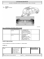
GLOBAL POSITIONING SYSTEM (GPS) MALFUNCTION - AF82.61-P-6010A
MODEL 163.113 /136 /154 /172 /174 #A as of 145273 up to 289564, 163.113 /154 #X as of 708319 up to
754619 with CODE (353) Audio 30 APS
Operation no. of operation texts or standard texts and flat rates
Sector
Op. no.
Operation text
Time
Acc. no.
P
023578
REPLACE REAR
003 AW/0,3 h 82 858 52
ANTENNA FOR
GLOBAL
POSITIONING
SYSTEM (GPS)
(AFTER TESTING)
Damage code
Code
-
Cause
Remedy
Inadequate seal between 1 Replace GPS antenna. AR82.61-P-7474GI
antenna base and vehicle
Use new parts kit
roof causes antenna
only.
connector to corrode.
The parts kit for the
Global Positioning
System (GPS) antenna
was updated. Instead of a
foam seal (4), a grommet
(5) is now used to seal the
antenna base to the
vehicle roof. The new
163 820 18 75 part
me
Saturday, October 02, 2010 3:30:07 PM
Page 174
© 2006 Mitchell Repair Information Company, LLC.
2001 Mercedes-Benz ML320
1998-2005 ACCESSORIES & BODY, CAB Electrical System - Body - 163 Chassis
number replaces the
former 163 820 06 75
part number.
Fig. 102: Identifying GPS Rear Antenna Components
Parts ordering notes
Part no.
163 820 18 75
Designation
Antenna
Quantity
1
TELEPHONE CALL INTERRUPTED - AF82.70-P-1009A
MODEL 129, 163, 168, 170, 171, 202, 203, 208, 209, 210, 211, 215, 220, 230, 460, 461, 463 with CODE
(312) GSM portable cellular telephone with CODE (316) MB GSM cellular telephone (D2B) with CODE
(317) GSM portable cellular telephone (D2B) with CODE (347) TELE AID emergency call system (D2B)
with CODE (380) Preinstallation for MB phone "CTEL", complete with CODE (381) MB phone
"Standard" in console on right side of dome with CODE (382) MB phone "CTEL" in console on right
side of dome with CODE (383) With telephone "Standard" in console on right side of dome with
integrated TELEAID emergency call system, hands-free system and antenna with CODE (386)
Preinstallation for "portable CTEL" UPCI telephone system with CODE (388) "Portable CTEL" UPCI
telephone system with CODE (852) CTEL preinstallation assembly at dome with CODE (853) MB
standard cellular telephone with CODE (854) MB portable cellular telephone with CODE (855) TELE
AID
Damage code
Cause
Remedy
me
Saturday, October 02, 2010 3:30:07 PM
Page 175
© 2006 Mitchell Repair Information Company, LLC.
2001 Mercedes-Benz ML320
1998-2005 ACCESSORIES & BODY, CAB Electrical System - Body - 163 Chassis
Network is overloaded
Do not remove/install/replace
any parts. It is not necessary to
The telephone
system has been
replace the telephone control
checked technically
module due to call interruptions.
1 Ask network provider about
traffic at point in question.
If the customer uses a twin
card it is necessary to switch off
the additionally (externally)
operated cellular telephone
before the vehicle's telephone
system is switched on.
LOSS OF SOUND IN COMAND SYSTEM AND/OR TELEPHONE NOT FUNCTIONING - AF82.70-P-1090A
MODEL 163, 203, 208, 209, 210, 215, 220, 230, 463 with CODE (853) MB standard cellular telephone
Nokia 6091
Damage code
Parts ordering notes
Part no.
A 203 820 70 26
Cause
Fixed installation telephone
control unit.
Cyclical loss of sound in
COMAND system for 2 - 3
seconds (Nokia 6091).
Telephone temporarily not
functioning.
Concerns fixed
installation control unit part
no. A 203 820 70 26. When
reading out with STAR
DIAGNOSIS (quick test)
part no. 000 000 00 00
appears with these control
units.
Affected Nokia series
numbers:
from 350109/20/038841/6
up to 350109/20/047721/9
Remedy
1 Read out series number.
via the receiver using the
key combination: *#06#
The series number can also be
found on the sticker on the
control unit.
If the affected series number
is installed: ?
2 Remove/install/replace fixed
installation telephone control
unit.
Designation
Fixed installation telephone
control unit
Quantity
As required
PORTABLE CTEL CANNOT BE OPERATED OVER STEERING WHEEL OR COMAND/RADIO - AF82.70-P-6090A
me
Saturday, October 02, 2010 3:30:07 PM
Page 176
© 2006 Mitchell Repair Information Company, LLC.
2001 Mercedes-Benz ML320
1998-2005 ACCESSORIES & BODY, CAB Electrical System - Body - 163 Chassis
MODEL 129, 163, 168, 170, 202, 203, 208, 210, 211, 215, 220 with CODE (380) Preinstallation for MB
phone "CTEL", complete with CODE (382) MB phone "CTEL" in console on right side of dome with
CODE (852) CTEL preinstallation assembly at dome with CODE (854) MB portable cellular telephone
with Nokia 6210
Modification notes
12.3.02
Damage code
Supersedes STIP 82.70035 dated 14.08.2001
Validity and content
updated
Cause
Nokia 6210 cannot be
operated with current
interface
Remedy
Operation of Nokia
6210 possible with new
interface. Modified
interface available.
Nokia 6210 portable
CTEL software version
4.36 or higher required
For model 211 the
portable CTEL SW
version 5.2 is required.
1 Read out Nokia 6210
portable CTEL software
version
2 Enter *#0000# on
Nokia 6210 portable
CTEL.
If an older version is
installed the portable
CTEL must be updated in
a Nokia shop.
If the customer has stored
data in the portable CTEL
telephone, it is necessary
to secure this in the
Nokia shop before
updating.
3 Remove and install,
replace interface.
MODEL 203.0 with
AR82.70-P-7379EE
CODE (854) MB
portable CTEL
MODEL 215, 220 up to AR82.70-P-8920I
30.6.00 with CODE (317)
D-network portable
CTEL (D2B)
MODEL 210.0 as of
AR82.70-P-7379FB
me
Saturday, October 02, 2010 3:30:07 PM
Page 177
© 2006 Mitchell Repair Information Company, LLC.
2001 Mercedes-Benz ML320
1998-2005 ACCESSORIES & BODY, CAB Electrical System - Body - 163 Chassis
1.7.00 with CODE (854)
MB portable CTEL
MODEL 208.3 as of
1.7.00 with CODE (854)
MB portable CTEL
Insert interference
suppression converter
between compensator
(A28/3) outlet in
direction of portable
CTEL holder.
Installation location
for compensator: ?
MODEL 203.0 with
CODE (854) MB
portable CTEL
MODEL 208.3 as of
1.7.00 with CODE (854)
MB portable CTEL
MODEL 210.0 with
CODE (854) MB
portable CTEL
MODEL 210.2 with
CODE (854) MB
portable CTEL
MODEL 215 as of 1.7.00
with CODE (854) MB
portable CTEL
MODEL 220 as of 1.7.00
with CODE (854) MB
portable CTEL
Return removed
interface (203 820 32 26)
with index ES1 0070 to
appropriate ELCs with
return slip.
To ensure supply of
replacement parts we
request you to send in the
removed interface
immediately.
Parts ordering notes
Part no.
203 820 51 85
Designation
Interface
AR82.70-P-7379EA
AR82.70-P-0010A
AR82.70-P-0010AC
AR82.70-P-0010B
AR82.70-P-0010C
AR82.70-P-0010AD
AR82.70-P-0010AE
Quantity
As required
me
Saturday, October 02, 2010 3:30:07 PM
Page 178
© 2006 Mitchell Repair Information Company, LLC.
2001 Mercedes-Benz ML320
1998-2005 ACCESSORIES & BODY, CAB Electrical System - Body - 163 Chassis
203 820 07 51
203 820 52 15
Clip for portable CTEL mount
As required
Interference suppression converter As required
COMAND OPERATING AND DISPLAY SYSTEM SCREEN REMAINS DARK AFTER STARTING ENGINE - AF82.85-P2001A
MODEL 163, 203, 208, 210, 215, 220, 230, 463 with CODE (352) COMAND operating and display system
Damage code
Cause
Remedy
Current vehicle voltage.
Do not remove/install
COMAND.
1. Point out to customer
that in the event of
problems the fault can
be eliminated by
switching off/on
(ON/OFF button) the
COMAND.
NAVIGATION SYSTEM DISPLAYS INCORRECT ADDRESS - AF82.85-P-2100A
MODEL 163.154 /174 #A as of 289565, 163.157/175 with CODE (357) Navigation system - additional unit
with CODE (494a) USA version
Mainland USA only,
DVD version 2002-2 only
Operation no. of the operation texts or standard texts and flat rates
Range
Op. no.
Operation text Flat rate
Acc. no.
P
023917
Flash Navigation 0.3 h
82 853 90
system
Damage code
Cause
Database mismatch.
Code
-
Remedy
1 Start engine.
2 Turn on MCS unit.
3 Press NAVI MENU
button.
4 Ensure MAP REGION
is set to MAINLAND US
under SYSTEM SETUP
menu.
5 Eject customer
Navigation DVD.
me
Saturday, October 02, 2010 3:30:07 PM
Page 179
© 2006 Mitchell Repair Information Company, LLC.
2001 Mercedes-Benz ML320
1998-2005 ACCESSORIES & BODY, CAB Electrical System - Body - 163 Chassis
6 Insert update CD into
Navigation unit and close
MCS door.
7 Follow on-screen
instructions until update
is complete.
DO NOT turn off
engine.
8 Remove update CD
when download is
complete.
Disregard error
message stating disc
cannot be read: There is
no map information on
the update CD.
9 Insert customer
Navigation DVD and
input any new address to
verify accuracy.
Parts ordering notes
Part no.
T-2787-163
Designation
Navigation update CD
Quantity
1
ERROR IN COMAND OPERATING AND DISPLAY SYSTEM - AF82.85-P-6000-01B
Error patterns for COMAND update CD 10/2001.
The service update CD COMAND with part number W 215 589 00 22 00 eliminates the following complaints:
COMAND: A 220 820 37 89
Error patterns:
Increased quiescent current.
The personal symbols on the map are not updated during active guidance.
Voice control does not react to commands
Occasionally no sound (duration approx. 1 second).
COMAND: A 203 820 91 89, A 463 820 10 89
Error patterns:
Increased quiescent current.
me
Saturday, October 02, 2010 3:30:07 PM
Page 180
© 2006 Mitchell Repair Information Company, LLC.
2001 Mercedes-Benz ML320
1998-2005 ACCESSORIES & BODY, CAB Electrical System - Body - 163 Chassis
The personal symbols on the map are not updated during active guidance.
Voice control does not react to commands
Occasionally no sound (duration approx. 1 second).
TV screen switches off when standing still
After switching on CD player plays CD1/track 1 instead of title played last
No message when CD magazine sticks during ejection
Wavy interference in navigation display when TV picture is switched off (as if station is not correctly
received)
TCS icons are occasionally not displayed on the map with active dynamic guidance
Telephone book is not activated.
COMAND: A 208 820 40 89, A 210 820 54 89, A 163 820 14 89
Error patterns:
Increased quiescent current.
The personal symbols on the map are not updated during active guidance.
Voice control does not react to commands
No message when CD magazine sticks during ejection
TCS cannot be activated sporadically.
Time in instrument cluster and COMAND differs approx. 1-2 seconds.
COMAND signals CD reading error without any obvious cause
PERFORMING SOFTWARE DOWNLOAD - AF82.85-P-6000-04A
COMAND 2.0-ECE / 2.5-ECE - Perform software download of CD:
Do not start vehicle during download, do not cause other voltage drops in the vehicle electrical system, do
not remove CD and do not switch off unit! (Unit will be damaged!)
In the case of erroneous operation of the download control module, the download starts again or is terminated if
the old software has not been erased previously.
1.
2.
3.
4.
Switch off ignition.
Remove navigation CD and insert download CD.
Switch off control module.
After a waiting time of min. 5 s and with buttons * and # pressed simultaneously, switch on unit.
The menu "Service download of CD" appears with menu points "Control module" and "Termination".
5. Select "Start control module" with right knob
me
Saturday, October 02, 2010 3:30:07 PM
Page 181
© 2006 Mitchell Repair Information Company, LLC.
2001 Mercedes-Benz ML320
1998-2005 ACCESSORIES & BODY, CAB Electrical System - Body - 163 Chassis
The date or the version of the currently stored software and the software on the CD appears in the
display.
By pressing the right knob the download is started. After some seconds the system changes to screen
"CD ROM software download".
On the download control module the main processor software is loaded first, then the graphic
processor software. Entire duration: approx. 40 minutes
The download progress is indicated by a bar graph.
In the event of errors an error message is indicated on the display.
When the download is completed, the display switches off for a short time. When it is switched back on
again the result of the download is displayed.
6. Remove download CD and reinsert navigation CD.
FAULT IN COMAND OPERATING AND DISPLAY SYSTEM - AF82.85-P-6000N
MODEL 163, 203, 208, 210, 215, 220, 463 with CODE (352a) COMAND operating and display system
with CODE (801) Model year 2001
MODEL 414 with CODE (EN4) Auto pilot system with TMC interface, large display with CODE (EN3)
Auto pilot system with GSM interface, large display
Modification notes
26.11.01
Supersedes AF82.85-P- Part numbers added and AF82.85-P-6000-01B
6000N dated 09.01.2002 changed
Operation no. of operation texts or standard texts and flat rates
Category
Op. no.
Operation text
Time
Acc. no.
P
829905
PERFORMING SW
003 WU/0.3 h UPDATE FOR
RADIO/COMAND
Damage code
Cause
Software error
Remedy
Error patterns for
COMAND update CD
10/2001.
1 Perform COMAND
update
Update only
COMAND with the
following part numbers.
A 163 820 14 89
Code
-
AF82.85-P-6000-01B
AF82.85-P-6000-04A
me
Saturday, October 02, 2010 3:30:07 PM
Page 182
© 2006 Mitchell Repair Information Company, LLC.
2001 Mercedes-Benz ML320
1998-2005 ACCESSORIES & BODY, CAB Electrical System - Body - 163 Chassis
A 203 820 91 89
A 208 820 40 89
A 210 820 54 89
A 220 820 37 89
A 463 820 10 89
CD covers exist with
incorrect part number for
model series 203.
Do not update part
number
A 203 820 96 89.
The CD should remain
in the workshop (service
CD)
It can be used several
times and should not be
given to customers!
Always order service CD
in advance to avoid
longer workshop visits!
Parts ordering notes
Part no.
W 215 589 00 22 00
Designation
COMAND service update CD
Quantity
1
AUDIO SYSTEM FAILS TO MUTE WHEN INCOMING PHONE CALLS RECEIVED - AF82.85-P-6010A
MODEL 163.113 /154 /172 /174 #A as of 221506 up to 289564, 163.113 #X as of 734088 up to 754619 with
CODE (352a) COMAND operating and display system with CODE (353) Audio 30 APS with CODE
(756b) MB Audio 10 CD radio with TP/RDS with CODE (819a) CD changer with CODE (854) MB
portable cellular telephone
Modification notes
17.9.01
Damage code
Supersedes STI no.
82.85-024 dated 14.9.01
Cause
Software error in CD
changer.
On vehicles equipped
with Code 352a, 756b or
353 in combination with
Code 819a and 854 the
audio system may
sporadically fail to automute when incoming
Remedy
1 Inspect CD changer
part number
If equipped with part
number: 163 820 15 89 ,
then ?
me
Saturday, October 02, 2010 3:30:07 PM
Page 183
© 2006 Mitchell Repair Information Company, LLC.
2001 Mercedes-Benz ML320
1998-2005 ACCESSORIES & BODY, CAB Electrical System - Body - 163 Chassis
phone calls are received.
2 Replace CD changer
See parts ordering
notes.
Parts ordering notes
Part no.
163 820 38 89
Designation
CD changer
AR82.64-P-7507GH
Quantity
1
NAVIGATION SYSTEM ERRONEOUS OR NO GUIDANCE - AF82.85-P-6061A
MODEL 163, 168, 170, 203, 208, 209, 210, 211, 215, 220, 230, 414, 463
Damage code
Cause
Defective digitization of
map material
Possible switch-off or
falsification of GPS
signals during worldwide
crisis
The satellite signal
includes the time at
which the signal was sent
The navigation processor
Calculate the
transmission time of the
signal resulting from the
satellite position and the
transmission time of the
GPS signal and can
therefore determine the
vehicle position (min. 3
satellites).
If the GPS signal is
falsified the transmitted
time from the satellites is
changed. A change of 10
ns corresponds to approx.
3 m position change
Remedy
1 Perform test drive with
other vehicle
This must be
compared with the same
navigation system and the
same version of
navigation CD.
If the complaint is still
present: ?
2 Perform test drive with
new navigation CD
version.
When the complaint is
eliminated, use new
navigation CD.
If the complaint is still
present: ?
3 Perform test drive with
other vehicle and
navigation system of
me
Saturday, October 02, 2010 3:30:07 PM
Page 184
© 2006 Mitchell Repair Information Company, LLC.
2001 Mercedes-Benz ML320
1998-2005 ACCESSORIES & BODY, CAB Electrical System - Body - 163 Chassis
other manufacturer.
If the complaint does
not occur during the test
drive, a digitization error
on the navigation CD is
present: ?
4 Inform customers of
facts and manufacturer of
CD with report form
If the correct report
form from the
manufacturer is not
available, please contact
corresponding service
center (telephone number
is given on label of
navigation CD):
5 Check antenna system
for proper function and
repair according to
condition.
If the antenna system
is okay and errors also
occur on other vehicles: ?
6 Inform customer that
the GPS system is
operated by the US
military
MCS MALFUNCTION - OCCASIONAL FAILURE OF STARGUIDE, SOUND OR CD CHANGER. DTC'S N1111, N1112, N1116
- AF82.95-P-6002A
MODEL 163.157 /174 /175 #A as of 409851 up to 419036 with CODE (349) E Call emergency call system
with CODE (522) Modular control system (MCS) radio USA
Operation no. of operation texts or standard texts and flat rates
Range
Op. no.
Operation text
Time
Acc. no.
P
023843
FLASH TELEAID
008 WU/0.7 h 82 876 90
EMERGENCY CALL
SYSTEM CONTROL
MODULE
Damage code
Code
-
Cause
Remedy
Data transmission of D2B Recode E-call control
ring is interrupted. The E- module: ?
call control module is in a
me
Saturday, October 02, 2010 3:30:07 PM
Page 185
© 2006 Mitchell Repair Information Company, LLC.
2001 Mercedes-Benz ML320
1998-2005 ACCESSORIES & BODY, CAB Electrical System - Body - 163 Chassis
bypass mode.
The E-call control
module is not recognized
by the D2B ring.
The emergency call
function is not affected,
this function is
INDEPENDENT of the
D2B ring.
1 Connect STARDIAGNOSIS.
2 Select "Information and
communication" in the
"Control module" menu
3 Select "TELE AID, Ecall or telephone telematic system (Kline)".
4 Select "Control module
version".
5 Check "Software
version".
If the "software
version" has the status of
04/03 , NO FURTHER
STEPS ARE
REQUIRED. If "Software
version" has the status of
02/02 ?
6 Select "Program control
module according to
factory data" in "TELE
AID" menu.
7 Follow instructions until
procedure is completed.
Complete DAS and
remove before SOS
button is pressed.
8 Connect STARDIAGNOSIS.
9 Perform short test and
erase all DTC's.
DTC's are stored in
MCS and E-call control
module.
10 Select "Control module
version" and "Software
version" in "TELE AID"
me
Saturday, October 02, 2010 3:30:07 PM
Page 186
© 2006 Mitchell Repair Information Company, LLC.
2001 Mercedes-Benz ML320
1998-2005 ACCESSORIES & BODY, CAB Electrical System - Body - 163 Chassis
menu and ensure that
software status 04/03 is
available.
11 Complete DAS and
finish STARDIAGNOSIS.
SELF-DIAGNOSTIC SYSTEM
INTERIOR LIGHTS DIAGNOSIS CONTENTS - AD82.20-P-1000GHZ
MODEL 163
A2.20 [] 11b
A2.2 [] 12b
A2.2 [] 14b
A2.2 [] 21b
Interior lighting
diagnosis, previous
knowledge
Interior lighting
diagnosis, function check
Interior lighting
diagnosis, troubleshooting
Interior lighting
diagnosis, testing
electrical system
AD82.20-P-2000GH
AD82.20-P-3000GH
AD82.20-P-5000GH
AD82.20-P-6000GH
INTERIOR LIGHTS DIAGNOSIS PREVIOUS KNOWLEDGE - AD82.20-P-2000GH
MODEL 163
Function description,
interior lighting
Location of components,
interior lighting
Electric wiring diagram,
interior lighting
Inter-function groups of
wiring diagrams
Connection and use of
test equipment
Diagnostic tools, interior
lighting
Assignment of coupling
on door separation points
GF82.20-P-0002GH
GF82.20-P-0002-01GH
PE82.20-P-2000G
PE00.19-P-1100E
AD00.00-P-1000AZ
AD54.21-P-2000-01GH
AD72.29-P-2000-03GH
INTERIOR LIGHTS DIAGNOSIS OPERATIONAL CHECK - AD82.20-P-3000GH
me
Saturday, October 02, 2010 3:30:07 PM
Page 187
© 2006 Mitchell Repair Information Company, LLC.
2001 Mercedes-Benz ML320
1998-2005 ACCESSORIES & BODY, CAB Electrical System - Body - 163 Chassis
MODEL 163
I
II
III
IV
Scope of test
Location of components, interior
lighting
Interior lighting diagnosis, previous
knowledge
Battery voltage 11-14 V
Fuses in order
AMM voltage supply in order
Lighting equipment in order
Function check
Operation/Requirement
GF82.20-P-000201GH
AD82.20-P-2000GH
AD54.21-P-600001GH
Specified value
1 Switch on front
interior lighting
manually
Possible cause/
Remedy
Cables E15/2
All doors closed, operate switch on Front dome lamp
front dome lamp (with shut-off delay (with shut-off delay
and front reading lamp)(E15/2).
and front reading
lamp) (E15/2)
illuminated
2 Switch on right rear All doors closed, operate switch on Right rear dome lamp Cables E15/9
interior lighting
right rear dome lamp (E15/9).
(E15/9) illuminated
manually
3 Switch on left rear All doors closed, operate switch on Left rear dome lamp Cables E15/8
interior lighting
left rear dome lamp (E15/8).
(E15/8) illuminated
manually
4 Switch on interior All doors closed, all interior lamps Front dome lamp
Rotary tumbler
lighting by opening a OFF, open left front or right front
(with shut-off delay microswitch
front door
door.
and front reading
AD80.20-P-600139GH
lamp) (E15/2), left
Interior lamps
rear dome lamp
(E15/8) and right rear AD82.20-P-5000GH
dome lamp (E15/9) Cables
dimmed
All-Activity Module
(AAM) (N10)
5 Switch on interior All doors closed, all interior lamps Left rear dome lamp Rotary tumbler
lighting by opening a OFF, open left rear or right rear
(E15/8) and right rear microswitch
rear door
door.
dome lamp (E15/9) AD80.20-P-600140GH
dimmed
Interior lamps
AD82.20-P-5000GH
Cables
All-Activity Module
(AAM) (N10)
6 Switch on interior Central locking in order All doors Front dome lamp
All-Activity Module
lighting by unlocking closed and locked, all interior lamps (with shut-off delay (AAM) (N10)
me
Saturday, October 02, 2010 3:30:07 PM
Page 188
© 2006 Mitchell Repair Information Company, LLC.
2001 Mercedes-Benz ML320
1998-2005 ACCESSORIES & BODY, CAB Electrical System - Body - 163 Chassis
vehicle
OFF, unlock vehicle with transmitter and front reading
key.
lamp) (E15/2), left
rear dome lamp
(E15/8) and right rear
dome lamp (E15/9)
dimmed
7 Switch on interior All doors closed, all interior lamps Front dome lamp
lighting by switching OFF, ignition OFF.
(with shut-off delay
off ignition
and front reading
lamp) (E15/2), left
rear dome lamp
(E15/8) and right rear
dome lamp (E15/9)
dimmed
8 Switch off interior All doors closed, interior lighting
Front dome lamp
lighting by switching switched on by opening a front door, (with shut-off delay
on ignition
ignition ON.
and front reading
lamp) (E15/2), left
rear dome lamp
(E15/8) and right rear
dome lamp (E15/9)
dimmed
9 Switch on rear
Switch on rear dome lamp (E15/3) Rear dome lamp
interior lighting
in "ON continuously" position.
(E15/3) illuminated
manually
10 Rear interior
Switch on rear dome lamp (E15/3) Rear dome lamp
lighting switches on in "Automatic" position, open rear (E15/3) illuminated
automatically
doors.
All-Activity Module
(AAM) (N10)
All-Activity Module
(AAM) (N10)
AD82.20-P-600003GH E15/3
AD80.20-P-600140GH
AD82.20-P-600003GH
E15/3
INTERIOR LIGHTS DIAGNOSIS TROUBLESHOOTING - AD82.20-P-5000GH
MODEL 163
I
II
III
Complaint
Interior lighting
Location of components,
interior lighting
Fuses in order
Battery voltage 11-14 V
AMM voltage supply in
order
Lighting equipment in order
Troubleshooting
Possible cause
Notes
Cables
GF82.20-P-0002-01GH
AD54.21-P-6000-01GH
Remedy/Test step
Voltage supply
me
Saturday, October 02, 2010 3:30:07 PM
Page 189
© 2006 Mitchell Repair Information Company, LLC.
2001 Mercedes-Benz ML320
1998-2005 ACCESSORIES & BODY, CAB Electrical System - Body - 163 Chassis
inoperative
Interior lighting does not All-Activity Module (AAM)
switch off with ignition (N10)
"ON", or does not switch
on with ignition "OFF"
Malfunctions only when
switched on
automatically (by
opening the doors):
None of the interior
Left front door rotary
lights come on when one tumbler microswitch
of the front doors is
(S87/7)
opened
Right front rotary tumbler
microswitch (S87/6) AllActivity Module (AAM)
(N10)
Rear interior lighting
Left rear door rotary
does not come on when tumbler microswitch
one of the rear doors is (S87/2) Right rear door
opened
rotary tumbler microswitch
(S87/3)
All-Activity Module (AAM)
(N10)
Front dome lamp (with Front dome lamp (with shutshut-off delay and front off delay and front reading
reading lamp) (E15/2) lamp) (E15/2)
does not come on when
the front doors are
opened.
Left rear dome lamp
Left rear dome lamp (E15/8) If E15/9 functions:
(E15/8) does not come All-Activity Module (AAM) otherwise:
on when the doors are (N10)
opened
Right rear dome lamp
Right rear dome lamp
If E15/8 functions:
(E15/9) does not come (E15/9)
otherwise:
on when the doors are All-Activity Module (AAM)
opened
(N10)
Malfunctions of
individual lamps only
(when switched on
automatically and
manually)
Front dome lamp (with Front dome lamp (with shutshut-off delay and front off delay and front reading
reading lamp) (E15/2) lamp)(E15/2)
inoperative
Terminal 30
N10
AD80.20-P-6001-39GH
Cables
N10
AD80.20-P-6001-40GH
Cables N10
AD82.20-P-6000-01GH
E15/2
E15/8
AD82.20-P-6000-02GH
E15/9
AD82.20-P-6000-02GH
Cables, E15/2
me
Saturday, October 02, 2010 3:30:07 PM
Page 190
© 2006 Mitchell Repair Information Company, LLC.
2001 Mercedes-Benz ML320
1998-2005 ACCESSORIES & BODY, CAB Electrical System - Body - 163 Chassis
Left rear dome lamp
(E15/8) inoperative
Right rear dome lamp
(E15/9) inoperative
Interior lighting does not
come on when central
locking is unlocked
Malfunctions of rear
dome lamp (E15/3):
Rear dome lamp (E15/3)
inoperative
Left rear dome lamp (E15/8)
Cables, E15/8
Right rear dome lamp
(E15/9)
Cables, E15/9
Central locking in order Cables N10
Rotary tumbler/trunk lid
microswitch (S88/1)
Rear dome lamp (E15/3)
AD82.20-P-6000-03GH
AD80.20-P-6001-44GH
INTERIOR LIGHTS TEST OF ELECTRICAL SYSTEM FRONT DOME LAMP - AD82.20-P-6000-01GH
Fig. 103: Interior Lights Test Of Electrical System Front Dome Lamp
INTERIOR LIGHTS TEST OF ELECTRICAL SYSTEM REAR LAMPS - AD82.20-P-6000-02GH
Fig. 104: Interior Lights Test Of Electrical System Rear Lamps
INTERIOR LIGHTS TEST OF ELECTRICAL SYSTEM REAR DOME LAMP - AD82.20-P-6000-03GH
Fig. 105: Interior Lights Test Of Electrical System Rear Dome Lamp
me
Saturday, October 02, 2010 3:30:07 PM
Page 191
© 2006 Mitchell Repair Information Company, LLC.
2001 Mercedes-Benz ML320
1998-2005 ACCESSORIES & BODY, CAB Electrical System - Body - 163 Chassis
INTERIOR LIGHTS TEST OF ELECTRICAL SYSTEM - AD82.20-P-6000GH
MODEL 163
I
II
III
1
2
3
4
5
6
Connection and use of
test equipment
Interior lighting
diagnosis, previous
knowledge
AAM voltage supply in
order
Battery voltage 11-14 V
Fuses in order
Lighting equipment in
order
Testing
Front dome lamp, testing
electrical system of
interior lighting
Rear lamps, testing
electrical system of
interior lighting
Rear dome lamp, testing
electrical system of
interior lighting
Front doors rotary
tumbler microswitch
Rear doors rotary tumbler
microswitch
Tailgate rotary tumbler
microswitch
AD00.00-P-1000AZ
AD82.20-P-2000GH
AD54.21-P-6000GH
AD82.20-P-6000-01GH
AD82.20-P-6000-02GH
AD82.20-P-6000-03GH
AD80.20-P-6001-39GH
AD80.20-P-6001-40GH
AD80.20-P-6001-44GH
WIPER SYSTEM DIAGNOSIS CONTENTS - AD82.30-P-1002GHZ
MODEL 163
A2.2 [] 11a
A2.2 [] 12a
A2.2 [] 14a
A2.2 [] 21a
Wiper system diagnosis,
previous knowledge
Wiper system diagnosis,
function check
Wiper system diagnosis,
troubleshooting
Wiper system, testing
electrical system
AD82.30-P-2002GH
AD82.30-P-3002GH
AD82.30-P-5002GH
AD82.30-P-6002GH
me
Saturday, October 02, 2010 3:30:07 PM
Page 192
© 2006 Mitchell Repair Information Company, LLC.
2001 Mercedes-Benz ML320
1998-2005 ACCESSORIES & BODY, CAB Electrical System - Body - 163 Chassis
WIPER SYSTEM DIAGNOSIS PREVIOUS KNOWLEDGE - AD82.30-P-2002GH
MODEL 163
Risk of injury due to
getting jammed or
crushed in extreme cases
due to limbs being
severed by coming into
contact with the
windshield wiper
mechanism
Location of components,
front screen wiper system
Location of components,
rear screen wiper system
Function description,
wiper system
Electric wiring diagram,
wiper system
Inter-function groups of
wiring diagrams
Connection and use of
test equipment
Diagnostic tools, wiper
system
Always remove the
ignition key when
working on the
windshield wiper
mechanism.
AS82.30-Z-0001-01A
GF82.30-P-0005-01GH
GF82.30-P-0004-01GH
GF82.30-P-0003GH
PE82.30-P-2000F
PE00.19-P-1100E
AD00.00-P-1000AZ
AD54.21-P-2000-01GH
WIPER SYSTEM DIAGNOSIS OPERATIONAL CHECK - AD82.30-P-3002GH
MODEL 163
Location of components, wiper
system
I
II
III
IV
Scope of test
Rear screen wiper
system
Front screen wiper
system
Wiper system diagnosis, previous
knowledge
Prerequisites for function check
Battery voltage 11-14V
Fuses in order
AAM voltage supply in order
Ignition (terminal 15) ON
Function check
Operation/requirement
&(GF82.30-P-000401GH)
&(GF82.30-P-000501GH)
AD82.30-P-2002GH
AD54.21-P-600001GH
Specified value
Possible cause/
me
Saturday, October 02, 2010 3:30:07 PM
Page 193
© 2006 Mitchell Repair Information Company, LLC.
2001 Mercedes-Benz ML320
1998-2005 ACCESSORIES & BODY, CAB Electrical System - Body - 163 Chassis
Remedy
Wiper runs at slower Cables
speed, while S4 is
AD82.30-P-600209GH
operated
AD82.30-P-600202GH
2 Front screen wiping Combination switch (S4) in
Wiper runs at slow
Cables
Stage 1
"Wiping stage 1" position
speed
AD82.30-P-600209GH
AD82.30-P-600202GH
3 Front screen wiping Combination switch (S4) in
Wiper runs quickly
Cables
Stage 2
"Wiping stage 2" position
AD82.30-P-600209GH
AD82.30-P-600202GH
4 Front screen
Combination switch (S4) in
Wiper runs, an
Cables
intermittent wiping
"Intermittent wiping" position.
interval of approx. 5 Intermittent wiper
seconds follows each control
complete wiping
AD82.30-P-6002process
01GH
5 Front screen
Combination switch (S4) in
Windshield washer
Cables
washing
"Washing" position
pump (M5/1) operates AD82.30-P-6002while S4 is actuated, 10GH
the wiper carries out AD82.30-P-6002three more wiper
04GH
processes after the
AD82.30-P-6002switch is released
02GH
6 Rear screen
Operate "Rear screen intermittent Rear wiper runs, an Cables
intermittent wipe
wipe" on rear window wiper/washer interval of approx. 5 AD82.30-P-6002switch (S78).
seconds follows each 06GH
AD82.30-P-6002complete wiping
process
08GH
7 Rear screen washing Operate "Rear screen intermittent The rear window
Cables
wipe" on rear window wiper/washer washer pump (M5/3) AD82.30-P-6002switch (S78).
operates while S78 is 06GH
operated, the wiper
AD82.30-P-6002carries on wiping for 08GH
AD82.30-P-60023 seconds after the
switch is released and 05GH
then stops in the rest
position
1 Tip wiping
Combination switch (S4) in "Tip
wiping" position
WIPER SYSTEM DIAGNOSIS TROUBLESHOOTING - AD82.30-P-5002GH
MODEL 163
me
Saturday, October 02, 2010 3:30:07 PM
Page 194
© 2006 Mitchell Repair Information Company, LLC.
2001 Mercedes-Benz ML320
1998-2005 ACCESSORIES & BODY, CAB Electrical System - Body - 163 Chassis
Location of components,
wiper system
Front screen
Rear screen
Complaint
Front wiper system
inoperative
Battery voltage 11-14 V
Fuses in order
AAM voltage supply in
order
Troubleshooting
Possible cause
Combination switch (S4)
AD54.21-P-6000-01GH
Notes
Wiper motor (M6/1)
Front wiper does not
function when washing
front screen
Windshield washer
pump does not function
when washing front
screen
Front wiper does not
function in wiping stage
1 or stage 2
&(GF82.30-P-000501GH)
&(GF82.30-P-000401GH)
Remedy/Test step
AD82.30-P-6002-09GH
AD82.30-P-600202GH, cables
AD82.30-P-6002-02GH
Wiper motor (M6/1)
Windshield washer pump
(M5/1)
AD82.30-P-6002-04GH
Combination switch (S4)
AD82.30-P-6002-09GH
Wiper motor (M6/1)
Combination switch (S4)
All-Activity Module (AAM)
(N10)
Cam-operated switch on
wiper motor (M6/1)
AD82.30-P-6002-02GH
AD82.30-P-6002-01GH
Rear window wiper/washer
switch (S78)
All-Activity Module (AAM)
(N10)
Rear window wiper
Rear window wiper/washer
inoperative
switch (S78)
Rear window wiper motor
inoperative (M6/4)
Rear window wiper does Rear window wiper/washer
not function when
switch (S78)
washing rear window
Rear window wiper
Rear window wiper motor
cannot be switched off relay (M6/4)
AD82.30-P-6002-06GH
Front wiper does not
function with
intermittent wiping
Front wiper does not
stop in rest position
when switched off.
Rear wiper system
inoperative
AD82.30-P-6002-07GH
AD82.30-P-6002-06GH
AD82.30-P-6002-08GH
AD82.30-P-6002-06GH
AD82.30-P-600203GH, cables
me
Saturday, October 02, 2010 3:30:07 PM
Page 195
© 2006 Mitchell Repair Information Company, LLC.
2001 Mercedes-Benz ML320
1998-2005 ACCESSORIES & BODY, CAB Electrical System - Body - 163 Chassis
Rear window wiper does
not complete a wiping
movement
Rear window washer
pump does not function
when washing rear
window
Cam-operated switch
Cam-operated switch on
rear window wiper motor
(M6/4)
Rear window wiper/washer
switch (S78)
AD82.30-P-6002-03GH
AD82.30-P-6002-06GH
Rear window washer pump
(M5/3)
AD82.30-P-6002-05GH
WIPER SYSTEM TEST OF ELECTRICAL SYSTEM INTERMITTENT WIPE - AD82.30-P-6002-01GH
Fig. 106: Wiper System Test Of Electrical System Intermittent Wipe
WIPER SYSTEM TEST OF ELECTRICAL SYSTEM WIPER MOTOR - AD82.30-P-6002-02GH
me
Saturday, October 02, 2010 3:30:07 PM
Page 196
© 2006 Mitchell Repair Information Company, LLC.
2001 Mercedes-Benz ML320
1998-2005 ACCESSORIES & BODY, CAB Electrical System - Body - 163 Chassis
Fig. 107: Wiper System Test Of Electrical System Wiper Motor
WIPER SYSTEM TEST OF ELECTRICAL SYSTEM TAILGATE WIPER RELAY - AD82.30-P-6002-03GH
Fig. 108: Wiper System Test Of Electrical System Tailgate Wiper Relay
WIPER SYSTEM TEST OF ELECTRICAL SYSTEM WASHER PUMP - AD82.30-P-6002-04GH
me
Saturday, October 02, 2010 3:30:07 PM
Page 197
© 2006 Mitchell Repair Information Company, LLC.
2001 Mercedes-Benz ML320
1998-2005 ACCESSORIES & BODY, CAB Electrical System - Body - 163 Chassis
Fig. 109: Wiper System Test Of Electrical System Washer Pump
WIPER SYSTEM TEST OF ELECTRICAL SYSTEM TAILGATE WASHER PUMP - AD82.30-P-6002-05GH
Fig. 110: Wiper System Test Of Electrical System Tailgate Washer Pump
WIPER SYSTEM TEST OF ELECTRICAL SYSTEM REAR WINDOW WIPER/WASHER SWITCH - AD82.30-P-6002-06GH
Fig. 111: Wiper System Test Of Electrical System Rear Window Wiper/Washer Switch
WIPER SYSTEM TEST OF ELECTRICAL SYSTEM CAM SWITCH - AD82.30-P-6002-07GH
1.0
Scope of test Measuring
instrument/
Test
connection
Front wiper
terminal 31
Operation/
Requirement
Specified
value
Possible
cause/Remedy
Combination
switch (S4) in
ON, OFF
when passing
Cables
me
Saturday, October 02, 2010 3:30:07 PM
Page 198
© 2006 Mitchell Repair Information Company, LLC.
2001 Mercedes-Benz ML320
1998-2005 ACCESSORIES & BODY, CAB Electrical System - Body - 163 Chassis
b
HHT actual
value
"Wipe stage 1"
position.
through rest
position
Cam-operated switch
on wiper motor
(M6/1)
WIPER SYSTEM TEST OF ELECTRICAL SYSTEM TAILGATE WIPER MOTOR - AD82.30-P-6002-08GH
Fig. 112: Wiper System Test Of Electrical System Tailgate Wiper Motor
WIPER SYSTEM TEST OF ELECTRICAL SYSTEM WIPER POSITIONS COMBINATION SWITCH - AD82.30-P-6002-09GH
Scope of test
Measuring instrument/ Test Operation/
connection
Requirement
1.0
Rest position 15
Contact 1
1.1
Intermittent
wipe
Contact 2
15
1.2
Tip wipe
Contact
15
1.3
Wipe stage 1 15
Contact
1.4
Wipe stage
17
Specified
value
19 Combination < 1 ohms
switch (S4) in
rest position
19 Combination < 1 ohms
switch (S4) in
"Intermittent
wipe" position
18 Combination < 1 ohms
switch (S4) in
"Tip wipe"
position
18 Combination < 1 ohms
switch (S4) in
"Wipe stage 1"
pos.
18 Combination < 1 ohms
Possible
cause/Remedy
S4
S4
S4
S4
S4
me
Saturday, October 02, 2010 3:30:07 PM
Page 199
© 2006 Mitchell Repair Information Company, LLC.
2001 Mercedes-Benz ML320
1998-2005 ACCESSORIES & BODY, CAB Electrical System - Body - 163 Chassis
2 Contact
1.5
Intermittent
wipe
Contact 1
switch (S4) in
"Wipe stage 2"
pos.
18 Combination < 1 ohms
switch (S4) in
"Intermittent
wipe" position
16
S4
WIPER SYSTEM TEST OF ELECTRICAL SYSTEM WASHER POSITION COMBINATION SWITCH - AD82.30-P-6002-10GH
Scope of Measuring instrument/ Test
test
connection
1.0
Wash
20
Contact
Operation/
Requirement
Specified
value
18 Combination
switch (S4) in
"Wash"
position
< 1 ohms
Possible
cause/Remedy
S4
WIPER SYSTEM TEST OF ELECTRICAL SYSTEM - AD82.30-P-6002GH
MODEL 163
I
II
III
1
2
Connection and use of
test equipment
Wiper system diagnosis,
previous knowledge
AAM voltage supply in
order
Battery voltage 11-14V
Fuses in order
Ignition (terminal 15) ON
Risk of injury due to
Always remove the
getting jammed or
ignition key when
crushed in extreme cases working on the
due to limbs being
windshield wiper
severed by coming into mechanism.
contact with the
windshield wiper
mechanism
Testing
Combination switch
wiper positions, testing
electrical system of wiper
system
Combination switch wash
positions, testing
AD00.00-P-1000AZ
AD82.30-P-2002GH
AD54.21-P-6000GH
AS82.30-Z-0001-01A
AD82.30-P-6002-09GH
AD82.30-P-6002-10GH
me
Saturday, October 02, 2010 3:30:07 PM
Page 200
© 2006 Mitchell Repair Information Company, LLC.
2001 Mercedes-Benz ML320
1998-2005 ACCESSORIES & BODY, CAB Electrical System - Body - 163 Chassis
3
4
5
6
7
8
9
10
electrical system of wiper
system
Intermittent wiper
control, testing electrical
system of wiper system
Cam-operated switch,
testing electrical system
of wiper system
Wiper motor, testing
electrical system of wiper
system
Washer pump, testing
electrical system of wiper
system
Trunk lid washer pump,
testing electrical system
of wiper system
Trunk lid wiper relay,
testing electrical system
of wiper system
Rear window
wiper/washer switch,
testing electrical system
of wiper system
Trunk lid wiper motor,
testing electrical system
of wiper system
AD82.30-P-6002-01GH
AD82.30-P-6002-07GH
AD82.30-P-6002-02GH
AD82.30-P-6002-04GH
AD82.30-P-6002-05GH
AD82.30-P-6002-03GH
AD82.30-P-6002-06GH
AD82.30-P-6002-08GH
RADIO (RD) DIAGNOSIS, CONTENTS - AD82.60-P-1000AZ
MODEL 124, 129, 140, 163, 168, 170, 202, 208, 210 with MB radio
MODEL 129, 140, 168, 170, 202, 208, 210 with MB radio and navigation operating unit, APS
I 3.1 [] 11
I 3.1 [] 12
I 3.1 [] 13
I 3.1 [] 14
I 3.1 [] 21
Radio (RD) diagnosis,
advanced information
Radio (RD) diagnosis,
function check
Radio (RD) diagnosis,
DTC memory
AD82.60-P-2000A
AD82.60-P-3000A
Models 129, 170, 202,
208, 210 as of 01.06.98
with digital data bus
(D2B)
Radio (RD) diagnosis,
troubleshooting
Radio (RD), testing
AD82.60-P-4000A
AD82.60-P-5000A
AD82.60-P-6000A
me
Saturday, October 02, 2010 3:30:07 PM
Page 201
© 2006 Mitchell Repair Information Company, LLC.
2001 Mercedes-Benz ML320
1998-2005 ACCESSORIES & BODY, CAB Electrical System - Body - 163 Chassis
electrical system
TOOLS, TESTING ELECTRICAL SYSTEM, RADIO (RD) - AD82.60-P-2000-01A
Fig. 113: Identifying Electrical Connecting Set (201 589 00 99 00)
Commercially available tools
Number
WH58.30-Z-1006-09A
Designation
Function generator
CONNECTIONS FOR RADIO, TESTING ELECTRICAL SYSTEM, RADIO (RD) - AD82.60-P-2000-02A
MB radio in models 129, 168, 170, 202, 208, 210 up to 31.05.98 and models 140, 163
me
Saturday, October 02, 2010 3:30:07 PM
Page 202
© 2006 Mitchell Repair Information Company, LLC.
2001 Mercedes-Benz ML320
1998-2005 ACCESSORIES & BODY, CAB Electrical System - Body - 163 Chassis
Fig. 114: Identifying Socket Connections For Radio
RADIO (RD) DIAGNOSIS ADVANCED INFORMATION - AD82.60-P-2000A
MODEL 124, 129, 140, 163, 168, 170, 202, 208, 210 with MB radio
MODEL 129, 140, 168, 170, 202, 208, 210 with MB radio and navigation operating unit, APS
Radio (RD), location of
controls
MB Classic radio with
GF82.60-P-0001-02A
traffic news decoder, with
RDS up to 08/95
MB Classic radio with
GF82.60-P-0001-02B
traffic news decoder, with
RDS as of 09/95 up to
01/97
MB Special radio with
GF82.60-P-0001-02C
traffic news decoder, with
RDS up to 05/98
MB Special radio with
GF82.60-P-0001-02D
CD compartment up to
05/98
MB Exquisite radio with GF82.60-P-0001-02E
traffic news decoder, with
RDS up to 05/98
MB Exquisite radio with GF82.60-P-0001-02F
traffic news decoder, with
RDS
MB APS radio and
GF82.60-P-0001-02G
navigation operating unit
up to 12/97
MB Audio 5 radio with GF82.60-P-0001-02H
traffic news decoder, with
RDS
GF82.60-P-0001-02I
MB Hi-line radio
GF82.60-P-0001-02J
MB Premium radio
MB ML 5 Audio radio
GF82.60-P-0001-02K
MB ML 10 Audio radio GF82.60-P-0001-02L
MB APS radio and
GF82.60-P-0001-02M
navigation operating unit
as of 01/98
MB Radio Audio 10 RDS GF82.60-P-0001-02N
as of 06/98 up to 06/99
MB Audio 10 RDS radio GF82.60-P-0001-02O
with CD compartment as
of 06/98
me
Saturday, October 02, 2010 3:30:07 PM
Page 203
© 2006 Mitchell Repair Information Company, LLC.
2001 Mercedes-Benz ML320
1998-2005 ACCESSORIES & BODY, CAB Electrical System - Body - 163 Chassis
MB Radio Audio 30 RDS GF82.60-P-0001-02P
as of 06/98
MB Audio 30 APS radio GF82.61-P-0002-03A
MB Radio Audio 10 RDS GF82.60-P-0001-02T
as of 07/99
Location and assignment Model 168
GF00.19-P-1000GC
of cables and connectors
Model 170
GF00.19-P-1000B
Summary of electric
Model 208
PE82.00-P-1100D
wiring diagrams
Model 202
PE82.00-P-1100D
Model 163
PE82.00-P-1100E
Model 168
PE82.00-P-1100GC
Model 170
PE82.00-P-1100B
Model 210
PE82.00-P-1100A
Model 202 up to 05.97
Group 82
and models 124, 129, 140
Connection and use of
AD00.00-P-1000AZ
test equipment
Tools, testing electrical
AD82.60-P-2000-01A
system, radio (RD)
Radio connections,
MB radio in models 129, AD82.60-P-2000-02A
testing electrical system, 168, 170, 202, 208, 210
radio (RD)
up to 05/98 and models
140, 163
MB APS radio and
AD82.60-P-2000-02B
navigation operating unit
in models 129, 140, 210
up to 12/97
MB APS radio and
AD82.60-P-2000-02C
navigation operating unit
in models 129, 140, 202,
210 as of 01/98
MB radio code 750a, 753, AD82.60-P-2000-02D
756a in models 129, 168,
170, 202, 208, 210 as of
06/98
MB APS radio and
AD82.61-P-2001-02A
navigation operating unit
in models 168, 170
Adjusting radio and
MB APS radio and
AD82.60-P-2000-03A
navigation operating unit navigation operating unit
to loudspeaker system,
in models 129, 140, 210
testing electrical system, up to 12/97
radio (RD)
me
Saturday, October 02, 2010 3:30:07 PM
Page 204
© 2006 Mitchell Repair Information Company, LLC.
2001 Mercedes-Benz ML320
1998-2005 ACCESSORIES & BODY, CAB Electrical System - Body - 163 Chassis
Function notes, radio
(RD)
Model 129
AD82.60-P-2000-04A
RADIO (RD) DIAGNOSIS, FUNCTION CHECK - AD82.60-P-3000A
MODEL 124, 129, 140, 163, 168, 170, 202, 208, 210 with MB radio
MODEL 129, 140, 168, 170, 202, 208, 210 with MB radio and navigation operating unit, APS
Radio (RD) diagnosis, advanced
information
Scope of test
1
Radio functions in
accordance with
Owner's Manual
AD82.60-P-2000A
Battery voltage 11-14 V
Fuses okay
Function check
Operation/Requirement
Specified value
Radio: ON
Set station with good reception
(music) or play music cassette or
CD.
Fader, bass, treble and balance in
position 0 (readout in display).
Perform all control functions
Possible cause/
Remedy
Radio reception,
AD82.60-P-5000A
cassettes/CD
Models 129, 170,202,
operation, loudness, 208, 210 as of 06/98
sound and readouts in with digital data bus
display must be
(D2B): ?
faultless
AD82.60-P-4000A
Local and
atmospheric
influences must be
taken into account
with radio reception.
They may cause
interference and poor
radio reception.
RADIO (RD) DIAGNOSIS, TROUBLESHOOTING - AD82.60-P-5000A
MODEL 124, 129, 140, 163, 168, 170, 202, 208, 210 with MB radio
MODEL 129, 140, 168, 170, 202, 208, 210 with MB radio and navigation operating unit, APS
Complaint
Radio completely
inoperative
Radio (RD) diagnosis,
previous knowledge
Troubleshooting
Possible cause
Voltage supply for radio
(A2) or APS radio and
AD82.60-P-2000A
Note
Remedy
AD82.60-P-6000-01A
me
Saturday, October 02, 2010 3:30:07 PM
Page 205
© 2006 Mitchell Repair Information Company, LLC.
2001 Mercedes-Benz ML320
1998-2005 ACCESSORIES & BODY, CAB Electrical System - Body - 163 Chassis
No readout in display
Cassette operation
inoperative
CD operation in radio
(A2) inoperative
CD operation, CD
changer (A2/6)
completely inoperative
navigation operating unit
(A2/29)
Voltage supply for radio
(A2) or APS radio and
navigation operating unit
(A2/29)
Voltage supply for radio
(A2) or APS radio and
navigation operating unit
(A2/29)
Voltage supply for radio
(A2) with CD compartment
Voltage supply for radio
(A2) or APS radio and
navigation operating unit
(A2/29)
Voltage supply, CD changer
(A2/6)
AD82.60-P-6000-01A
AD82.60-P-6000-01A
AD82.60-P-6000-01A
MB radio and CD
AD82.60-P-6000-01A
changer
AD82.60-P-6000-01B
Models 129, 140, 168,
202, 208, 210 up to
05/98
Models 124, 163
MB APS radio and
navigation operating unit
and CD changer
Models 129, 140,202,
210
CD operation, CD
Voltage supply for radio
MB radio and CD
AD82.60-P-6000-01A
changer (A2/6)
(A2) or APS radio and
changer
AD82.60-P-6000-01C
completely inoperative navigation operating unit
Models 129, 140, 168,
(A2/29)
202, 208, 210 as of
Voltage supply, CD changer 06/98
(A2/6)
MB APS radio and
navigation operating unit
and CD changer
Model 168
Left front loudspeaker Radio (A2) or APS radio
AD82.60-P-6000-02A
inoperative
and navigation operating
unit (A2/29), loudspeaker
Right front loudspeaker Radio (A2) or APS radio
AD82.60-P-6000-03A
inoperative
and navigation operating
unit (A2/29), loudspeaker
Left rear loudspeaker
Radio (A2) or APS radio
AD82.60-P-6000-04A
inoperative
and navigation operating
unit (A2/29), loudspeaker
Right rear loudspeaker Radio (A2) or APS radio
AD82.60-P-6000-05A
inoperative
and navigation operating
unit (A2/29), loudspeaker
Radio interference
Radio (A2) or APS radio
AD82.60-P-6000-06A
and navigation operating
me
Saturday, October 02, 2010 3:30:07 PM
Page 206
© 2006 Mitchell Repair Information Company, LLC.
2001 Mercedes-Benz ML320
1998-2005 ACCESSORIES & BODY, CAB Electrical System - Body - 163 Chassis
Poor radio reception
Automatic antenna
(M11) inoperative
unit (A2/29), antenna
Radio (A2) or radio and
navigation operating unit
(APS) (A2/29), antenna,
coverage
Radio (A2) or radio and
navigation operating unit
(APS) (A2/29), automatic
antenna (M11)
Speed-sensitive loudness Radio (A2) or radio and
control (GAL)
navigation operating unit
inoperative
(APS) (A2/29), vehicle
speed signal
Radio or radio and
Radio (A2) or radio and
navigation operating unit navigation operating unit
illumination inoperative (APS) (A2/29)
Radio mute circuit
Radio (A2) or radio and
(Mute) inoperative when navigation operating unit
using phone
(APS) (A2/29), telephone
system
With auto pilot system Radio and navigation
(APS): No fader
operating unit (APS)
function or loudspeaker (A2/29) not tuned to
sound quality inadequate loudspeaker system
AD82.60-P-6000-07A
Except
AD82.60-P-6000-08A
only
Except model 163
AD82.60-P-6000-08B
AD82.60-P-6000-09A
AD82.60-P-6000-10A
AD82.60-P-6000-11A
Models 129, 140, 210 up AD82.60-P-2000-03A
to 31.12.97
VOLTAGE SUPPLY, TESTING ELECTRICAL SYSTEM, RADIO (RD) - AD82.60-P-6000-01A
Fig. 115: Voltage Supply, Testing Electrical System, Radio (RD)
VOLTAGE SUPPLY, TESTING ELECTRICAL SYSTEM, RADIO (RD) - AD82.60-P-6000-01B
MB radio and CD changer, code 819 in models 129, 140, 168, 202, 208, 210 up to 31.05.98 and in models
124, 163 MB APS radio and navigation operating unit and CD changer, code 819 in models 129, 140, 202,
210
me
Saturday, October 02, 2010 3:30:07 PM
Page 207
© 2006 Mitchell Repair Information Company, LLC.
2001 Mercedes-Benz ML320
1998-2005 ACCESSORIES & BODY, CAB Electrical System - Body - 163 Chassis
Fig. 116: Voltage Supply, Testing Electrical System, Radio (RD)
LEFT FRONT LOUDSPEAKER OUTPUT, TESTING ELECTRICAL SYSTEM RADIO (RD) - AD82.60-P-6000-02A
Fig. 117: Left Front Loudspeaker Output, Testing Electrical System Radio (RD)
RIGHT FRONT LOUDSPEAKER OUTPUT, TESTING ELECTRICAL SYSTEM RADIO (RD) - AD82.60-P-6000-03A
Fig. 118: Right Front Loudspeaker Output, Testing Electrical System Radio (RD)
me
Saturday, October 02, 2010 3:30:07 PM
Page 208
© 2006 Mitchell Repair Information Company, LLC.
2001 Mercedes-Benz ML320
1998-2005 ACCESSORIES & BODY, CAB Electrical System - Body - 163 Chassis
LEFT REAR LOUDSPEAKER OUTPUT, TESTING ELECTRICAL SYSTEM RADIO (RD) - AD82.60-P-6000-04A
Fig. 119: Left Rear Loudspeaker Output, Testing Electrical System Radio (RD)
RIGHT REAR LOUDSPEAKER OUTPUT, TESTING ELECTRICAL SYSTEM, RADIO (RD) - AD82.60-P-6000-05A
Fig. 120: Right Rear Loudspeaker Output, Testing Electrical System, Radio (RD)
RADIO INTERFERENCE, TESTING ELECTRICAL SYSTEM, RADIO (RD) - AD82.60-P-6000-06A
1.0
1.1
Scope of test Measuring
instrument/
Test
connection
Radio (A2) or
Radio :
navigation
operating
unit (APS)
(A2/29)
Radio
interference
when engine
is not running
Radio
interference
when engine
is running
Operation/Requirement
Specified
value
Radio: ON
No
Set even transmitter
interference
frequency without
transmitter reception (e.g.
96.0).
Ignition: ON
Radio: ON
No
Set even transmitter
interference
frequency without
transmitter reception (e.g.
Possible
cause/Remedy
Ground
connections
Cables
Electronic
components
==>1.1
Ground
connections
Cables
me
Saturday, October 02, 2010 3:30:07 PM
Page 209
© 2006 Mitchell Repair Information Company, LLC.
2001 Mercedes-Benz ML320
1998-2005 ACCESSORIES & BODY, CAB Electrical System - Body - 163 Chassis
96.0)
Engine: Start
Electronic
components
Ignition system
Engine timing
Values in order :
Antenna systems
(AS)
RADIO RECEPTION, TESTING ELECTRICAL SYSTEM, RADIO (RD) - AD82.60-P-6000-07A
1.0
Scope of test Measuring
instrument/
Test
connection
Radio (A2)
or Radio :
navigation
operating
unit (APS)
(A2/29)
Radio
reception
Operation/Requirement
Specified
value
Radio: ON
Set station with good
reception:
Carry out road test
Radio
reception in
order
Possible
cause/Remedy
Ground
connections
Cables
Radio or APS
radio and
navigation
operating unit
Radio transmitter
Broadcasting
corporation
Values in order:
Antenna systems
(AS)
ACTUATION FOR AUTOMATIC ANTENNA, TESTING ELECTRICAL SYSTEM, RADIO (RD) - AD82.60-P-6000-08A
expect
Fig. 121: Actuation For Automatic Antenna, Testing Electrical System, Radio (RD)
me
Saturday, October 02, 2010 3:30:07 PM
Page 210
© 2006 Mitchell Repair Information Company, LLC.
2001 Mercedes-Benz ML320
1998-2005 ACCESSORIES & BODY, CAB Electrical System - Body - 163 Chassis
RADIO ILLUMINATION, TESTING ELECTRICAL SYSTEM, RADIO (RD) - AD82.60-P-6000-10A
Fig. 122: Radio Illumination, Testing Electrical System, Radio (RD)
RADIO MUTE CIRCUIT, TESTING ELECTRICAL SYSTEM, RADIO (RD) - AD82.60-P-6000-11A
Scope of
test
1.0
Measuring instrument/ Test Operation/Requirement Specified
connection
value
Radio
8 (A.8)
(A2) or
radio and
navigation
operating
unit (APS)
(A2/29)
Radio mute
circuit
through
telephone
system
(phone)
3 (A.3) Remove radio or
operating unit
Do not disconnect
couplings Carry out test
at coupling A Radio:
ON
Radio
switches
to mute,
PHONE
appears
in
display
Possible
cause/Remedy
Cables
Radio or APS
radio and
navigation
operating unit
Telephone
system
RADIO (RD), TESTING ELECTRICAL SYSTEM - AD82.60-P-6000A
MODEL 124, 129, 140, 163, 168, 170, 202, 208, 210 with MB radio
MODEL 129, 140, 168, 170, 202, 208, 210 with MB radio and navigation operating unit
Radio (RD) diagnosis,
advanced information
AD82.60-P-2000A
Carry out test of
loudspeaker outputs
me
Saturday, October 02, 2010 3:30:07 PM
Page 211
© 2006 Mitchell Repair Information Company, LLC.
2001 Mercedes-Benz ML320
1998-2005 ACCESSORIES & BODY, CAB Electrical System - Body - 163 Chassis
1
2
3
4
5
6
7
8
9
10
additionally with one
individual loudspeaker.
In the event of reception
faults, carry out test
additionally with a
separate antenna.
Switch off radio for
disconnecting and
connecting connections
and connectors on the
radio and loudspeaker
system.
Battery voltage 1114 V
Fuses in order
Testing
Voltage supply, testing
electrical system, radio (RD)
Voltage supply, testing
electrical system, radio (RD)
Voltage supply for
AD82.60-P-6000-01A
radio, terminal 30
Voltage supply for CD AD82.60-P-6000-01B
changer in models 129,
140, 168, 202, 208, 210
up to 05/98 and models
124, 163
Voltage supply, testing
Voltage supply for CD AD82.60-P-6000-01C
electrical system, radio (RD) changer in models 129,
140, 168, 202, 208, 210
as of 06/98
Left front loudspeaker output,
AD82.60-P-6000-02A
testing electrical system, radio
(RD)
Right front loudspeaker output,
AD82.60-P-6000-03A
testing electrical system, radio
(RD)
Left rear loudspeaker output,
AD82.60-P-6000-04A
testing electrical system, radio
(RD)
Right rear loudspeaker output,
AD82.60-P-6000-05A
testing electrical system, radio
(RD)
Radio interference, testing
AD82.60-P-6000-06A
electrical system, radio (RD)
Radio reception, testing
AD82.60-P-6000-07A
electrical system, radio (RD)
Actuation for automatic
AD82.60-P-6000-08A
except
antenna, testing electrical
me
Saturday, October 02, 2010 3:30:07 PM
Page 212
© 2006 Mitchell Repair Information Company, LLC.
2001 Mercedes-Benz ML320
1998-2005 ACCESSORIES & BODY, CAB Electrical System - Body - 163 Chassis
11
12
13
14
system, radio (RD)
Actuation for automatic
antenna, testing electrical
system, radio (RD)
Speed-sensistive loudness
control, testing electrical
system, radio (RD)
Radio illumination, testing
electrical system, radio (RD)
Radio mute circuit, testing
electrical system, radio (RD)
only
AD82.60-P-6000-08B
except model 163
AD82.60-P-6000-09A
AD82.60-P-6000-10A
AD82.60-P-6000-11A
CONTENTS - AUDIO 30 APS DIAGNOSIS - AD82.61-P-1001AZ
MODEL 163,168,170, 208, 210 with CODE (353) Audio 30 APS
I 9.4 [] 11
I 9.4 [] 12
I 9.4 [] 13
I 9.4 [] 14
I 9.4 [] 21
Audio 30 APS diagnosis,
basic knowledge
Audio 30 APS diagnosis,
function check
Audio 30 APS diagnosis,
DTC memory
Audio 30 APS diagnosis,
troubleshooting
Audio 30 APS, testing
electric system
AD82.61-P-2001A
AD82.61-P-3001A
AD82.61-P-4002A
AD82.61-P-5001A
AD82.61-P-6001A
AUDIO 30 APS DIAGNOSIS TOOLS - AD82.61-P-2001-01A
Fig. 123: Identifying Electrical Connection Set (201 589 00 99 00)
me
Saturday, October 02, 2010 3:30:07 PM
Page 213
© 2006 Mitchell Repair Information Company, LLC.
2001 Mercedes-Benz ML320
1998-2005 ACCESSORIES & BODY, CAB Electrical System - Body - 163 Chassis
Fig. 124: Identifying Adapter Cable (140 589 22 63 00)
Commercially available tools
Number
WH58.30-Z-1001-09A
Designation
Multimeter
Designation
MB radio removal tool
(000 833 03 61)
RADIO AND NAVIGATION UNIT CONNECTOR ASSIGNMENTS - AD82.61-P-2001-02A
Connectors on radio and navigation unit (A2/56)
me
Saturday, October 02, 2010 3:30:07 PM
Page 214
© 2006 Mitchell Repair Information Company, LLC.
2001 Mercedes-Benz ML320
1998-2005 ACCESSORIES & BODY, CAB Electrical System - Body - 163 Chassis
Fig. 125: Identifying Radio And Navigation Unit Connector Assignments
VERSION CODING FOR RADIO AND NAVIGATION UNIT - AD82.61-P-2001-03A
The table below shows the possible navigation system adaptations to the vehicle. The settings can be changed
with the aid of the handheld tester ("HHT").
Navigation parameters
ABS pulse count (pulse count
from wheel speed sensor per
wheel rotation)
Tire size
Tire condition
Coding is required only when
tires are changed. Tire wear
occurring while driving is
recognized automatically by the
navigation system.
Possible settings
Factory setting:
e.g.:
48 (passenger cars)
195/50/15
Guideline values:
Tread depth greater than 5 mm
New:
me
Saturday, October 02, 2010 3:30:08 PM
Page 215
© 2006 Mitchell Repair Information Company, LLC.
2001 Mercedes-Benz ML320
1998-2005 ACCESSORIES & BODY, CAB Electrical System - Body - 163 Chassis
Used:
Tread depth less than 5 mm
AUDIO 30 APS DIAGNOSIS, BASIC KNOWLEDGE - AD82.61-P-2001A
MODEL 163,168,170, 208, 210 with CODE (353) Audio 30 APS
In order to avoid damage
to control modules,
connectors must only be
disconnected or
connected with "terminal
15R:OFF "
Local or atmospheric
influences can cause
disruption to radio or
satellite reception.
Satellite reception is
possible only in the open
air.
Position finding with
assistance of global
positioning system data
(in degrees of longitude
and latitude) takes place
within a period of 1 to
20min after "ignition: ON
".
The audio 30 APS is a
navigation system with
integrated radio and CD
player and . It also
provides an interface for
external audio
components via a digital
data bus (D2B). Existing
DMNL deals mainly with
navigation system.
Diagnosis of the
following systems: radio,
D2B, loudspeaker
system (LS), CD
changer and sound
system can be extracted
from the appropriate
DMNL.
Audio 30 APS operating
GF82.61-P-0002-03A
me
Saturday, October 02, 2010 3:30:08 PM
Page 216
© 2006 Mitchell Repair Information Company, LLC.
2001 Mercedes-Benz ML320
1998-2005 ACCESSORIES & BODY, CAB Electrical System - Body - 163 Chassis
notes
Audio 30 APS location of Model 163
components
Model 168
Model 170
Models 208, 210
Location and assignment Model 163
of cable and plug
connections
Model 168
Model 170
Model 208
Model 210
Overview of electrical
Model 163
wiring diagrams
Model 168
Model 170
Model 208
Model 210
Connection and use of
test equipment
Diagnostic tools, Audio
30 APS
Variant coding, radio and
navigation unit
Connector assignment,
radio and navigation unit
GF82.61-P-0002-01D
GF82.61-P-0002-01B
GF82.61-P-0002-01A
GF82.61-P-0002-01C
GF00.19-P-1000E
GF00.19-P-1000GC
GF00.19-P-1000B
GF00.19-P-1000D
GF00.19-P-1000A
PE82.00-P-1100E
PE82.00-P-1100GC
PE82.00-P-1100B
PE82.00-P-1100D
PE82.00-P-1100A
AD00.00-P-1000AZ
AD82.61-P-2001-01A
AD82.61-P-2001-03A
AD82.61-P-2001-02A
AUDIO 30 APS DIAGNOSIS, FUNCTION CHECK - AD82.61-P-3001A
MODEL 163,168,170, 208, 210 with CODE (353) Audio 30 APS
Scope of test
Audio 30 APS diagnosis, basic
knowledge
See specified diagnosis
manuals for function checks on
the following systems: radio
(RD), AM/FM antenna systems
(ATS) and loudspeaker system
(LSA).
Fuses okay
Battery voltage 11-14 V
Function check
Action/prerequisites
Nominal value
AD82.61-P-2001A
Possible cause /
me
Saturday, October 02, 2010 3:30:08 PM
Page 217
© 2006 Mitchell Repair Information Company, LLC.
2001 Mercedes-Benz ML320
1998-2005 ACCESSORIES & BODY, CAB Electrical System - Body - 163 Chassis
1 GPS reception
2 Navigation
remedy
The current location is
AD82.61-P-5001A
indicated in terms of
latitude and longitude,
e.g.:
LONGIT. 9:01.37E
LATIT. 48:42.17N In
addition, the number of
satellites received is
indicated.
It is necessary to
receive at least 3 satellite
signals for twodimensional GPS location
finding.
Local or atmospheric
influences can cause
interruptions in the
reception of the GPS
signals.
Ignition: ON
Route calculation may take AD82.61-P-5001A
Radio and navigation unit
up to 30 s.
(A2/56): ON
Recommendations for
If necessary: insert navigation guidance or output on the
CD ROM into radio and
radio loudspeakers ( voice
navigation unit (A2/56) .
output ) and on the A2/56
Press "NAV" button.
display with the aid of
Check GPS reception (see
route guidance symbols
above) Enter a destination in ( pictograms ).
the vicinity with the aid of the Pay particular attention to
"ADDRESS ENTRY" menu the time the voice
and activate guidance feature messages are output (the
by selecting:
messages should not be
FASTEST ROUTE or
output too early or too
SHORTEST ROUTE or OWN late). Also observe bar
SETTINGS.
graph display.
Drive vehicle along test route
If the vehicle is on a
"non-digitized" road
(company yard, parking
lot, country road) the
display "OFF ROAD"
appears. When driving
outside of the digitized
map boundaries the
display "OFF MAP"
appears.
Vehicle outdoors under free
sky
Ignition: ON
Radio and navigation unit
(A2/56): ON
Press "I" button (info).
Wait a few minutes if
necessary.
me
Saturday, October 02, 2010 3:30:08 PM
Page 218
© 2006 Mitchell Repair Information Company, LLC.
2001 Mercedes-Benz ML320
1998-2005 ACCESSORIES & BODY, CAB Electrical System - Body - 163 Chassis
AUDIO 30 APS DIAGNOSIS, DTC MEMORY - AD82.61-P-4002A
MODELS 163,168,170, 208, 210 with CODE (353) Audio 30 APS
Audio 30 APS
diagnosis, previous
knowledge
Connect hand-held- Model 163 up to 31.8.01, 168
tester (HHT), read out
diagnostic trouble
code memory
Models 170, 208, 210
DTC
No fault code
B1000
AD82.61-P-2001A
AD00.00-P-200003C
AD00.00-P-200003A
Communication
See also: Information/Communication AD82.00-P-1000AZ
between the HHT and Diagnosis Manual Index 13.1 Digital AD82.64-P-1000AZ
all other D2B
data bus (D2B)
components also
See also: Information/Communication
takes place via the
Diagnosis Manual Index 6.1 Compact
diagnostic interface disc player with CD changer
of the radio and
navigation unit
(A2/56) .
ForDTC's affecting
the digital data bus
(D2B) , theCD
changer (A2/6) and
the sound system ,
remedy measures are
given in the
corresponding
diagnosis manuals.
Fuses okay
Battery voltage 1114V
The RDS data
evaluation is
deactivated during
HHT diagnosis.
Diagnostic trouble
code memory
Possible cause
Note
Remedy
No fault detected
Nevertheless if there is a complaint: ? AD82.61-P-5001A
Audio 30 APS diagnosis,
troubleshooting
Internal error in radio
A2/56
and navigation unit
me
Saturday, October 02, 2010 3:30:08 PM
Page 219
© 2006 Mitchell Repair Information Company, LLC.
2001 Mercedes-Benz ML320
1998-2005 ACCESSORIES & BODY, CAB Electrical System - Body - 163 Chassis
B1010
B1011
B1088
B1734
B1738
(A2/56)
Radio and
navigation unit
(A2/56) switches off
due to undervoltage
Radio and
navigation unit
(A2/56) switches off
due to overvoltage
Only on model 208,
The radio and navigation unit
210:
(A2/56) is connected to the
Malfunction in CAN instrument cluster (A1) via a separate
connection between CAN bus.
instrument cluster Read out instrument cluster (A1)
(A1) and radio and DTC memory
navigation unit
(A2/56)
Model 163:
The wheel speed signals are passed
Wheel speed signal to the radio and navigation unit
from CAN bus
(A2/56) via a separate line and not
adapter missing
directly on CAN.
Model 168:
See also: Chassis Diagnosis Manual,
Signal from left rear index 9 or index 10: ?
wheel speed sensor Index 10.4 ESP (Model 163)
(L6/3) missing
Index 10.3 ESP (Model 168)
Model 170:
Index 10.2 ESP (Model 208, 210)
Signal from left front Index 10.5 ESP (Model 208)
wheel speed sensor
(L6/1) missing
Models 208, 210:
Signal from right
front wheel speed
sensor (L6/2)
missing
Models 168, 208.4:
GPS antenna
(A2/49a2) or lead
defective
Models 170, 208.3:
Rear GPS antenna
(A2/23a2) or lead
defective
Model 163:
The GPS and telephone radio
Telephone and GPS signals are transmitted between A2/49
roof antenna (A2/49) and A2/57 via a common antenna
or telephone and
cable.
AD82.61-P-600101A
AD82.61-P-600101A
CAN line between
A1 and A2/56
AD82.61-P-600103A
AD42.45-P-1002AZ
AD42.45-P1002GCZ
AD42.45-P-1000AZ
See STAR
DIAGNOSIS
AD82.61-P-600105A
AD82.61-P-600105B
me
Saturday, October 02, 2010 3:30:08 PM
Page 220
© 2006 Mitchell Repair Information Company, LLC.
2001 Mercedes-Benz ML320
1998-2005 ACCESSORIES & BODY, CAB Electrical System - Body - 163 Chassis
B1763
B1765
N1111
N1112
N1113
N1114
N1115
N1116
N1117
N1118
N1140
N1141
N1250
N1251
N1252
N1253
N1254
GPS antenna
splitter (A2/57) or
lead defective
Excessive
temperature or
reading error of CD
drive of radio and
navigation unit
(A2/56)
Gyrosensor defective
Fiber optic cable
defective, Individual
D2B units defective
or power supply for
individual D2B units
Only on model 208,
210:
DTC in CAN
connection between
instrument cluster
(A1) and radio and
navigation unit
(A2/56)
Nominal-actual
configuration of D2B
ring varies
CD changer
Excess temperature
CD changer
CD reading error
CD changer
CD magazine error
CD changer
Hardware error
(mechanical)
CD changer
Insufficient
temperature
Remove CD-ROM
from drive and check
for contamination
and damage. A2/56
A2/56
See also: ?
Model 168, 170,
Information/Communication Diagnosis 208, 210
Manual Index 13.1 Digital data bus
AD82.00-P-4000A
(D2B)
CAN line between
The radio and navigation unit
A1 and A2/56
(A2/56) is connected to the
instrument cluster (A1) via a separate
CAN bus.
DTC memory for instrument cluster
(A1)
See also: ?
Reconfigure system
Information/Communication Diagnosis AD82.00-P-4000A
Manual Index 13.1 Digital data bus
(D2B)
Lower temperature
inside vehicle
Check CD changer
Check CD magazine
Check hardware
components and
replace if necessary
Heating passenger
compartment
AUDIO 30 APS DIAGNOSIS, TROUBLESHOOTING - AD82.61-P-5001A
MODEL 163,168,170, 208, 210 with CODE (353) Audio 30 APS
me
Saturday, October 02, 2010 3:30:08 PM
Page 221
© 2006 Mitchell Repair Information Company, LLC.
2001 Mercedes-Benz ML320
1998-2005 ACCESSORIES & BODY, CAB Electrical System - Body - 163 Chassis
Audio 30 APS operating
notes
Audio 30 APS location of
components
GF82.61-P-0002-03A
Model 163
GF82.61-P-0002-01D
Model 168
Model 170
Models 208, 210
GF82.61-P-0002-01B
GF82.61-P-0002-01A
GF82.61-P-0002-01C
AD82.61-P-2001A
Audio 30 APS diagnosis,
previous knowledge
Battery voltage 11-14V
Troubleshooting
Complaint
Cause
Note
Radio and navigation
Fuse in A2/56, Voltage
unit (A2/56) completely supply for A2/56, Defect at
inoperative
navigation CD-ROM,
A2/56
No communication
K line, Radio and
possible between Hand- navigation unit (A2/56)
Held Tester (HHT) and
Audio 30 APS
Navigation inoperative Navigation CD-ROM is not
loaded or is incorrectly
loaded or incorrect /
defective CD-ROM
Radio and navigation unit
(A2/56)
Destination finding
Check wheel calibration
system messages are
and variant coding
given too early or too late
(e.g. "please turn right")
The expected arrival
Time on radio and
time is not correct
navigation unit (A2/56) is
incorrectly set
Navigation is defective
or imprecise
Remedy
AD82.61-P-6001-01A
AD82.61-P-6001-02A
Load navigation CD,
refer to:
GF82.61-P-0002-03A
AD82.61-P-2001-03A
Check variant coding and Models 163, 168, 170
wheel calibration,
Models 208, 210
Reversing signal,
Wheel speed signal,
Models 163, 168, 208.3,
210:
Cellular telephone and GPS
roof antenna (A2/49),
Models 170, 208.4:
GPS rear antenna
(A2/23a2)
Actuate "NAV"
pushbutton and activate
"CLOCK" menu, set
time
Refer to:
AD82.61-P-2001-03A
AD82.61-P-6001-04A
AD82.61-P-6001-04B
AD82.61-P-6001-03A
AD82.61-P-6001-05A
me
Saturday, October 02, 2010 3:30:08 PM
Page 222
© 2006 Mitchell Repair Information Company, LLC.
2001 Mercedes-Benz ML320
1998-2005 ACCESSORIES & BODY, CAB Electrical System - Body - 163 Chassis
No reception of GPS
data
Radio or loudspeaker
functional faults and poor
sound with voice output
Voice output is
fragmentary or
inoperative, but audio
signal replay (e.g. CD
player) functions without
complaint.
Illumination of radio and
navigation unit (A2/56)
inoperative (with terminal
58d, ON)
Radio and navigation unit
(A2/56)
Antenna cable or
Model 163:
Cellular telephone and GPS
roof antenna (A2/49) or
cellular telephone and GPS
antenna splitter (A2/57)
Models 168, 208.3, 210:
Cellular telephone and GPS
roof antenna (A2/49)
Models 170, 208.4:
GPS rear antenna
(A2/23a2)
Radio and navigation unit
(A2/56)
Loudspeaker system or
amplifier outputs of radio
and navigation unit
(A2/56). Only with sound
system (code 810):
Left/right audio power
amplifier (N40/3)
Voice in RAM of
navigation computer is
partly erased as a result of
an interruption in voltage
supply.
Data fault on navigation
CD-ROM
Radio and navigation unit
(A2/56)
Terminal 58d signal is not
on radio and navigation
unit (A2/56) .
On models 208, 210,
terminal 58d is not
connected, because A2/56
is connected to A1 via
CAN.
On model 163 only
one antenna cable (for
telephone and GPS)
leads to A2/49. A
defective antenna cable
would therefore effect a
telephone, if connected.
Model 163
AD82.61-P-6001-05B
Models 168,
170,208,210
AD82.61-P-6001-05A
Antenna amplifier test Refer to DMNL
can be carried out using information /
HHT.
communication
Index 3 (RD)
Index 5 (LS)
Avoid excessive
shaking while loading
voice on A2/56.
Replace CD-ROM
AD82.61-P-6001-06A
RADIO AND NAVIGATION UNIT, POWER SUPPLY, CHECKING ELECTRICAL SYSTEM, AUDIO 30 APS - AD82.61-P6001-01A
me
Saturday, October 02, 2010 3:30:08 PM
Page 223
© 2006 Mitchell Repair Information Company, LLC.
2001 Mercedes-Benz ML320
1998-2005 ACCESSORIES & BODY, CAB Electrical System - Body - 163 Chassis
Fig. 126: Radio And Navigation Unit, Power Supply, Checking Electrical System, Audio 30 APS
HHT INTERFACE, TESTING, ELECTRICAL SYSTEM, AUDIO 30 APS - AD82.61-P-6001-02A
Fig. 127: HHT Interface, Testing, Electrical System, Audio 30 APS
AUDIO 30 APS TEST OF ELECTRICAL SYSTEM WHEEL SPEED SIGNAL - AD82.61-P-6001-03A
&(AD42.45-P-1002BZ)
me
Saturday, October 02, 2010 3:30:08 PM
Page 224
© 2006 Mitchell Repair Information Company, LLC.
2001 Mercedes-Benz ML320
1998-2005 ACCESSORIES & BODY, CAB Electrical System - Body - 163 Chassis
Fig. 128: Audio 30 APS Test Of Electrical System Wheel Speed Signal
REVERSE SIGNAL, TESTING, ELECTRICAL SYSTEM, AUDIO 30 APS - AD82.61-P-6001-04A
me
Saturday, October 02, 2010 3:30:08 PM
Page 225
© 2006 Mitchell Repair Information Company, LLC.
2001 Mercedes-Benz ML320
1998-2005 ACCESSORIES & BODY, CAB Electrical System - Body - 163 Chassis
Fig. 129: Reverse Signal, Testing, Electrical System, Audio 30 APS
AUDIO 30 APS TEST OF ELECTRICAL SYSTEM GPS ANTENNA - AD82.61-P-6001-05B
Fig. 130: Audio 30 APS Test Of Electrical System GPS Antenna
RADIO AND NAVIGATION UNIT, ILLUMINATION, TESTING, ELECTRICAL SYSTEM, AUDIO SYSTEM 30 APS AD82.61-P-6001-06A
me
Saturday, October 02, 2010 3:30:08 PM
Page 226
© 2006 Mitchell Repair Information Company, LLC.
2001 Mercedes-Benz ML320
1998-2005 ACCESSORIES & BODY, CAB Electrical System - Body - 163 Chassis
Fig. 131: Radio And Navigation Unit, Illumination, Testing, Electrical System, Audio System 30 APS
AUDIO 30 APS, TESTING, ELECTRICAL SYSTEM - AD82.61-P-6001A
MODEL 163,168,170, 208, 210 with CODE (353) Audio 30 APS
1
2
3
Audio 30 APS, location Model 163
of components
Audio 30 APS, location Model 168
of components
Audio 30 APS, location Model 170
of components
Audio 30 APS, location Model 208, 210
of components
Audio 30 APS operating
instructions
Audio 30 APS diagnosis,
basic knowledge
Connector assignments
on radio and navigation
unit
Battery voltage 11 -14 V
Testing
Radio and navigation unit
power supply, testing,
electrical system, Audio
30 APS
HHT interface, testing,
electrical system, Audio
30 APS
Wheel speed signal,
testing, electrical system,
Audio 30 APS
GF82.61-P-0002-01D
GF82.61-P-0002-01B
GF82.61-P-0002-01A
GF82.61-P-0002-01C
GF82.61-P-0002-03A
AD82.61-P-2001A
AD82.61-P-2001-02A
AD82.61-P-6001-01A
AD82.61-P-6001-02A
AD82.61-P-6001-03A
me
Saturday, October 02, 2010 3:30:08 PM
Page 227
© 2006 Mitchell Repair Information Company, LLC.
2001 Mercedes-Benz ML320
1998-2005 ACCESSORIES & BODY, CAB Electrical System - Body - 163 Chassis
4
5
6
7
8
Backup signal, testing,
AD82.61-P-6001-04A
electrical system, Audio
30 APS Model 163, 168,
170
Backup signal, testing,
AD82.61-P-6001-04B
electrical system, Audio
30 APS Model 208, 210
GPS antenna, testing,
Model 168, 170, 208, 210 AD82.61-P-6001-05A
electrical system, Audio
30 APS
GPS antenna, testing,
Model 163
AD82.61-P-6001-05B
electrical system, Audio
30 APS
Radio and navigation
AD82.61-P-6001-06A
unit, illumination, testing,
electrical system, Audio
30 APS
ANTENNA SYSTEM (AS) DIAGNOSIS, CONTENTS - AD82.62-P-1000AZ
MODELS 163, 168, 202.078 /080 /083 /182 /188, 208 (except, 208.4), 202.01 /02/12 as of 1.1.97, 210.0 /2
I 4.4 [] 11
I 4.4 [] 12
I 4.4 [] 21
Antenna system (AS)
diagnosis, previous
knowledge
Antenna system (AS)
diagnosis, function check
Antenna systems (AS),
testing electrical system
AD82.62-P-2000A
AD82.62-P-3000A
AD82.62-P-6000A
SPEAKER SYSTEM (LSA) DIAGNOSIS CONTENTS - AD82.62-P-1001AZ
MODEL 163 with CODE (491) U.S. version with CODE (259) Radio Premium with Bose sound system
MODEL 163 with CODE (259a) Radio ML 10 with sound system except CODE (491) U.S. version
MODEL 208 with CODE (810) Sound system with MB radio
I 5.13 [] 11
I 5.13 [] 12
I 5.13 [] 13a
Loudspeaker system (LS)
diagnosis, previous
knowledge
Loudspeaker system (LS)
diagnosis, function check
Loudspeaker system (LS) Model 208
diagnosis, troubleshooting
AD82.62-P-2001A
AD82.62-P-3001A
AD82.62-P-5001A
me
Saturday, October 02, 2010 3:30:08 PM
Page 228
© 2006 Mitchell Repair Information Company, LLC.
2001 Mercedes-Benz ML320
1998-2005 ACCESSORIES & BODY, CAB Electrical System - Body - 163 Chassis
I 5.13 [] 13b
I 5.13 [] 21a
I 5.13 [] 21b
Loudspeaker system (LS) Model 163
diagnosis, troubleshooting
Loudspeaker system (LS) Model 208
testing electrical system
Loudspeaker system (LS) Model 163
testing electrical system
AD82.62-P-5001E
AD82.62-P-6001A
AD82.62-P-6001E
LOUDSPEAKER SYSTEM (LS) DIAGNOSIS, CONTENTS - AD82.62-P-1001BZ
MODEL 163 with CODE (491) U.S. version with CODE (257) Radio Hi-Line
MODEL 163 with CODE (257a) Radio ML 5 except CODE (491) U.S. version
MODEL 168,208 with MB radio
I 5.12 [] 11
I 5.12 [] 12
I 5.12 [] 13a
I 5.12 [] 13b
I 5.12 [] 13c
I 5.12 [] 21a
I 5.12 [] 21b
I 5.12 [] 21c
Loudspeaker system (LS)
diagnosis, advanced
information
Loudspeaker system (LS)
diagnosis, function check
Loudspeaker system (LS) Model 208
diagnosis, troubleshooting
Loudspeaker system (LS) Model 168
diagnosis, troubleshooting
Loudspeaker system (LS) Model 163
diagnosis, troubleshooting
Loudspeaker system (LS), Model 208
testing electrical system
Loudspeaker system (LS), Model 168
testing electrical system
Loudspeaker system (LS), Model 163
testing electrical system
AD82.62-P-2001B
AD82.62-P-3001A
AD82.62-P-5001B
AD82.62-P-5001C
AD82.62-P-5001D
AD82.62-P-6001B
AD82.62-P-6001C
AD82.62-P-6001D
TOOLS, DIAGNOSIS, ANTENNA SYSTEMS (AS) - AD82.62-P-2000-01A
Fig. 132: Identifying Electrical Connection Set (201 589 00 99 00)
me
Saturday, October 02, 2010 3:30:08 PM
Page 229
© 2006 Mitchell Repair Information Company, LLC.
2001 Mercedes-Benz ML320
1998-2005 ACCESSORIES & BODY, CAB Electrical System - Body - 163 Chassis
Commercially available tools
Number
WH58.30-Z-1001-09A
Designation
Multimeter
ANTENNA SYSTEM (AS) TEST DIAGRAM - AD82.62-P-2000-02D
Model 163
Test diagram for FM/AM radio/amplifier
Model 163:
Fig. 133: Antenna System (AS) Test Diagram
ANTENNA SYSTEM (AS) DIAGNOSIS, PREVIOUS KNOWLEDGE - AD82.62-P-2000A
MODELS 163, 168, 202.078 /080 /083 /182 /188, 208 (except, 208.4), 202.01 /02/12 as of 1.1.97, 210.0 /2
Antenna system
(AS), location of
components
MODEL 208 (except 208.4)
MODELS 202.01/02/12 as of 01.01.97
MODELS
202.078/080/083/182/188/210.2
Model 168
GF82.62-P-000103A
GF82.62-P-000103B
GF82.62-P-0001-
me
Saturday, October 02, 2010 3:30:08 PM
Page 230
© 2006 Mitchell Repair Information Company, LLC.
2001 Mercedes-Benz ML320
1998-2005 ACCESSORIES & BODY, CAB Electrical System - Body - 163 Chassis
03C
GF82.62-P-000103D
GF82.62-P-000103H
Model 163
Model 210.0
Wiring diagrams
MODEL 202 up to 31.05.97, group 82
Models 202, 208 from 01.06.97
Model 168
Model 163
Model 210
Connecting and
using test
equipment
Tooling diagnosis,
antenna system
(AS)
Checking chart for MODEL 208 except 208.4
AS
MODELS 202.01/02/12 as of 01.01.97
MODELS
202.078/080/083/182/188/210.2
Model 168
Model 163
Model 210.0
PE82.00-P-1100D
PE82.00-P-1100GC
PE82.00-P-1100E
PE82.00-P-1100A
AD00.00-P1000AZ
AD82.62-P-200001A
AD82.62-P-200002A
AD82.62-P-200002B
AD82.62-P-200002C
AD82.62-P-200002D
AD82.62-P-200002F
DIAGNOSTIC TOOLS, LOUDSPEAKER SYSTEM (LS) - AD82.62-P-2001-01A
Fig. 134: Identifying Electrical Connecting Set (201 589 00 99 00)
Commercially available tools
Number
WH58.30-Z-1001-09A
WH58.30-Z-1006-09A
Designation
Multimeter
Function generator
me
Saturday, October 02, 2010 3:30:08 PM
Page 231
© 2006 Mitchell Repair Information Company, LLC.
2001 Mercedes-Benz ML320
1998-2005 ACCESSORIES & BODY, CAB Electrical System - Body - 163 Chassis
COUPLING ASSIGNMENT ON RADIO FOR LOUDSPEAKER SYSTEM (LS) - AD82.62-P-2001-02A
All MB radios
Coupling B
Fig. 135: Identifying Coupling Assignment On Radio For Loudspeaker System (LS)
LOUDSPEAKER SYSTEM (LS) DIAGNOSIS, ADVANCED INFORMATION - AD82.62-P-2001A
MODEL 163 with CODE (491) U.S. version with CODE (259) Radio Premium with Bose sound system
MODEL 163 with CODE (259a) Radio ML 10 with sound system except CODE (491) U.S. version
MODEL 208 with CODE (810) Sound system with MB radio
Loudspeaker system
(LS), location of
components
Model 208
GF82.62-P-0002-01A
Model 163
Electric wiring diagram, Model 208
radio with sound system
Model 163
Connection and use of
test equipment
Diagnostic tools,
loudspeaker system (LS)
Coupling assignment on
radio for loudspeaker
system (LS)
GF82.62-P-0002-01E
PE82.00-P-1100D
PE82.00-P-1100E
AD00.00-P-1000AZ
AD82.62-P-2001-01A
AD82.62-P-2001-02A
LOUDSPEAKER SYSTEM (LS) DIAGNOSIS, ADVANCED INFORMATION - AD82.62-P-2001B
MODEL 163 with CODE (491) U.S. version with CODE (257) Radio Hi-Line
me
Saturday, October 02, 2010 3:30:08 PM
Page 232
© 2006 Mitchell Repair Information Company, LLC.
2001 Mercedes-Benz ML320
1998-2005 ACCESSORIES & BODY, CAB Electrical System - Body - 163 Chassis
MODEL 163 with CODE (257a) Radio ML 5 except CODE (491) U.S. version
MODEL 168, 208 with MB radio
Loudspeaker system
(LS), location of
components
Model 208
GF82.62-P-0002-01B
Model 168 Model
163
Electric wiring diagrams Model 208
Model 168
Model 163
Connection and use of
test equipment
Diagnostic tools,
loudspeaker system (LS)
Coupling assignment on
radio for loudspeaker
system (LS)
GF82.62-P-0002-01C
GF82.62-P-0002-01D
PE82.00-P-1100D
PE82.00-P-1100GC
PE82.00-P-1100E
AD00.00-P-1000AZ
AD82.62-P-2001-01A
AD82.62-P-2001-02A
AM AND FM WAVE BANDS, DIAGNOSIS, FUNCTION CHECK, AS - AD82.62-P-3000-01A
Function check
Set radio as follows: Set station with poor reception (music) and fader, bass, treble and balance in
position 0 (shown in display).
Check AM and FM wave bands by driving in a circle in a yard (open-air grounds) to establish the
reception quality.
Possibly repeat the test with an identical vehicle for comparison.
It is absolutely essential to perform the comparison measurement at the same location and with the same
station setting .
Repeat the test after replacing a component.
ANTENNA SYSTEM (AS) DIAGNOSIS, FUNCTION CHECK - AD82.62-P-3000A
MODELS 163, 168, 202.078 /080 /083 /182 /188, 208 (except, 208.4), 202.01 /02/12 as of 1.1.97, 210.0 /2
Test of
Antenna system (AS)
diagnosis, previous
knowledge
Operational check
Operation /
Requirement
AD82.62-P-2000A
Specified value
possible cause/ Remedy
me
Saturday, October 02, 2010 3:30:08 PM
Page 233
© 2006 Mitchell Repair Information Company, LLC.
2001 Mercedes-Benz ML320
1998-2005 ACCESSORIES & BODY, CAB Electrical System - Body - 163 Chassis
1
AM and FM wavebands
diagnosis, AS function
check
AD82.62-P-3000-01A
LOUDSPEAKER SYSTEM (LS) DIAGNOSIS, FUNCTION CHECK - AD82.62-P-3001A
MODEL all with MB radio
Set station with good
reception (music) or play
music cassette or CD
Fader, bass, treble and balance
in position 0 (shown in
display).
Function check
Operation/Requirement
Specified value
Scope of test
1 Loudspeaker
Possible
cause/Remedy
Listen to each loudspeaker
individually in the respective
installed position.
SPEAKER SYSTEM (LSA) DIAGNOSIS TROUBLESHOOTING - AD82.62-P-5001D
MODEL 163 with CODE (491) U.S. version with CODE (257) Radio Hi-Line
MODEL 163 with CODE (257a) Radio ML 5 except CODE (491) U.S. version
Loudspeaker system (LS),
diagnosis, advanced
information
Loudspeaker system (LS),
location of components
Troubleshooting
Complaint
Cause
Left front door speaker Loudspeaker (H4/5)
(H4/5) inoperative
Radio (A2)
Left rear door speaker Loudspeaker (H4/3)
(H4/3) inoperative
Radio (A2)
Right front door speaker Loudspeaker (H4/6)
(H4/6) inoperative
Radio (A2)
Right rear door speaker Loudspeaker (H4/4)
(H4/4) inoperative
Radio (A2)
AD82.62-P-2001B
GF82.62-P-0002-01D
Note
Remedy
AD82.62-P-6001-02M
AD82.62-P-6001-02O
AD82.62-P-6001-02P
AD82.62-P-6001-02R
SPEAKER SYSTEM (LSA) DIAGNOSIS TROUBLESHOOTING - AD82.62-P-5001E
me
Saturday, October 02, 2010 3:30:08 PM
Page 234
© 2006 Mitchell Repair Information Company, LLC.
2001 Mercedes-Benz ML320
1998-2005 ACCESSORIES & BODY, CAB Electrical System - Body - 163 Chassis
MODEL 163 with CODE (491) U.S. version with CODE (259) Radio Premium with Bose sound system
MODEL 163 with CODE (259a) Radio ML 10 with sound system except CODE (491) U.S. version
Loudspeaker system (LS)
diagnosis, previous
knowledge
LS, location of components
Troubleshooting
Complaint
Cause
Note
Loudspeaker system
Amplifier control module
inoperative
(N40/6)
Radio (A2)
Left rear door speaker Left rear door speaker
(H4/3) inoperative
(H4/3)
Amplifier control module
(N40/6)
Radio (A2)
Right rear door speaker Loudspeaker group (H4/4)
(H4/4) inoperative
Amplifier control module
(N40/6)
Radio (A2)
Left front door speaker Loudspeaker group (H4/5)
(H4/5) inoperative
Amplifier control module
(N40/6)
Radio (A2)
Right front door speaker Loudspeaker (H4/6)
(H4/6) inoperative
Amplifier control module
(N40/6)
Radio (A2)
Acoustimass (R) bass
Loudspeaker (H4/17)
module (H4/17)
inoperative
Amplifier control module
(N40/6)
Radio (A2)
AD82.62-P-2001A
GF82.62-P-0002-01E
Remedy
AD82.62-P-6001-01C
AD82.62-P-6001-02S
AD82.62-P-6001-01C
AD82.62-P-6001-02T
AD82.62-P-6001-01C
AD82.62-P-6001-02U
AD82.62-P-6001-01C
AD82.62-P-6001-02V
AD82.62-P-6001-01C
AD82.62-P-6001-04A
AD82.62-P-6001-01C
RADIO FREQUENCY CONNECTING LINE, ANTENNA SYSTEM (AS) ELECTRICAL SYSTEM TEST - AD82.62-P-6000-02A
me
Saturday, October 02, 2010 3:30:08 PM
Page 235
© 2006 Mitchell Repair Information Company, LLC.
2001 Mercedes-Benz ML320
1998-2005 ACCESSORIES & BODY, CAB Electrical System - Body - 163 Chassis
Fig. 136: Radio Frequency Connecting Line, Antenna System (AS) Electrical System Test
VOLTAGE SUPPLY, ANTENNA SYSTEM (AS) ELECTRICAL SYSTEM TEST - AD82.62-P-6000-03A
Fig. 137: Voltage Supply, Antenna System (AS) Electrical System Test
FM/AM AMPLIFIER POWER CONSUMPTION, ANTENNA SYSTEM (AS) ELECTRICAL SYSTEM TEST - AD82.62-P-600004A
me
Saturday, October 02, 2010 3:30:08 PM
Page 236
© 2006 Mitchell Repair Information Company, LLC.
2001 Mercedes-Benz ML320
1998-2005 ACCESSORIES & BODY, CAB Electrical System - Body - 163 Chassis
Fig. 138: FM/AM Amplifier Power Consumption, Antenna System (AS) Electrical System Test
FM/AM AMPLIFIER GROUND CONNECTION, ANTENNA SYSTEM (AS) ELECTRICAL SYSTEM TEST - AD82.62-P-600005A
Test of
1.0
Gauge/test connection
Ground
connection
FM/AM
amplifier
(A2/18)
Operation/
Requirement
Specified
value
A2/18 Radio (A2): OFF < 1 ohms
Do not release
attachment at
FM/AM amplifier
(A2/18). The
attachment point
of the amplifier
simultaneously
serves as the
ground
connection.
Possible
cause/
Remedy
Transition
impedance at
ground
connection
ANTENNA SYSTEMS (AS), TESTING ELECTRICAL SYSTEM - AD82.62-P-6000A
MODELS 163, 168, 202.078 /080 /083 /182 /188, 208 (except, 208.4), 202.01 /02/12 as of 1.1.97, 210.0 /2
Antenna system (AS)
diagnosis, previous
knowledge
AD82.62-P-2000A
Battery voltage
11-14V>
me
Saturday, October 02, 2010 3:30:08 PM
Page 237
© 2006 Mitchell Repair Information Company, LLC.
2001 Mercedes-Benz ML320
1998-2005 ACCESSORIES & BODY, CAB Electrical System - Body - 163 Chassis
Fuses OK
Radio in order
No damage to
the rear
window and/or
to the rear or
side window
Inspecting
Rear window
except MODELS 163, 210.2
suppressor capacitor
antenna system (AS)
electrical system test
Radio frequency
connecting line,
antenna system (AS)
electrical system test
Radio frequency
MODELS 202.078/080/083/182/188
connecting line,
antenna system (AS)
electrical system test
Voltage supply,
antenna system (AS)
electrical system test
FM/AM amplifier
power consumption,
antenna system (AS)
electrical system test
FM/AM amplifier
ground connection,
antenna system (AS)
electrical system test
Test step
1
2
3
4
5
6
AD82.62-P-600001A
AD82.62-P-600002A
AD82.62-P-6000-02B
AD82.62-P-600003A
AD82.62-P-600004A
AD82.62-P-600005A
AMPLIFIER CONTROL MODULE TEST ELECTRICS LSA - AD82.62-P-6001-01C
Model 163 with sound system
me
Saturday, October 02, 2010 3:30:08 PM
Page 238
© 2006 Mitchell Repair Information Company, LLC.
2001 Mercedes-Benz ML320
1998-2005 ACCESSORIES & BODY, CAB Electrical System - Body - 163 Chassis
Fig. 139: Amplifier Control Module Test Electrics LSA
AMPLIFIER CONTROL MODULE TEST ELECTRICS LSA - AD82.62-P-6001-01D
Model 163 with sound system
Fig. 140: Amplifier Control Module Test Electrics LSA
SPEAKER TEST ELECTRICS LSA - AD82.62-P-6001-02M
Models 163/168
Fig. 141: Speaker Test Electrics LSA
SPEAKER TEST ELECTRICS LSA - AD82.62-P-6001-02O
Models 163, 168, 202, 210
me
Saturday, October 02, 2010 3:30:08 PM
Page 239
© 2006 Mitchell Repair Information Company, LLC.
2001 Mercedes-Benz ML320
1998-2005 ACCESSORIES & BODY, CAB Electrical System - Body - 163 Chassis
Fig. 142: Speaker Test Electrics LSA
SPEAKER TEST ELECTRICS LSA - AD82.62-P-6001-02P
Models 163 /168
Fig. 143: Speaker Test Electrics LSA
SPEAKER TEST ELECTRICS LSA - AD82.62-P-6001-02R
Models 163, 168, 202, 210
Fig. 144: Speaker Test Electrics LSA
SPEAKER TEST ELECTRICS LSA - AD82.62-P-6001-02S
Model 163 with sound system
me
Saturday, October 02, 2010 3:30:08 PM
Page 240
© 2006 Mitchell Repair Information Company, LLC.
2001 Mercedes-Benz ML320
1998-2005 ACCESSORIES & BODY, CAB Electrical System - Body - 163 Chassis
Fig. 145: Speaker Test Electrics LSA
SPEAKER TEST ELECTRICS LSA - AD82.62-P-6001-02T
Model 163 with sound system
Fig. 146: Speaker Test Electrics LSA
SPEAKER TEST ELECTRICS LSA - AD82.62-P-6001-02U
Model 163 with sound system
Fig. 147: Speaker Test Electrics LSA
me
Saturday, October 02, 2010 3:30:08 PM
Page 241
© 2006 Mitchell Repair Information Company, LLC.
2001 Mercedes-Benz ML320
1998-2005 ACCESSORIES & BODY, CAB Electrical System - Body - 163 Chassis
SPEAKER TEST ELECTRICS LSA - AD82.62-P-6001-02V
Model 163 with sound system
Fig. 148: Speaker Test Electrics LSA
LS TEST OF ELECTRICAL SYSTEM BASE SPEAKER - AD82.62-P-6001-04A
Model 163 with sound system
Fig. 149: LS Test Of Electrical System Base Speaker
SPEAKER SYSTEM (LSA) TEST ELECTRICS - AD82.62-P-6001D
MODEL 163 with CODE (491) U.S. version with CODE (257) Radio Hi-Line
MODEL 163 with CODE (257a) Radio ML 5 except CODE (491) U.S. version
Loudspeaker system (LS)
diagnosis, advanced
information
AD82.62-P-2001B
me
Saturday, October 02, 2010 3:30:08 PM
Page 242
© 2006 Mitchell Repair Information Company, LLC.
2001 Mercedes-Benz ML320
1998-2005 ACCESSORIES & BODY, CAB Electrical System - Body - 163 Chassis
1
2
3
4
Battery voltage 1114 V
Fuses in order
Radio in order
Switch off radio for
disconnecting and
connecting connections
and connectors on the
radio and loudspeaker
system.
Testing
Loudspeaker, testing
electrical system, LS
Loudspeaker, testing
electrical system, LS
Loudspeaker, testing
electrical system, LS
Loudspeaker, testing
electrical system, LS
Left front door
AD82.62-P-6001-02M
Left rear door
AD82.62-P-6001-02O
Right front door
AD82.62-P-6001-02P
Right rear door
AD82.62-P-6001-02R
SPEAKER SYSTEM (LSA) TEST ELECTRICS - AD82.62-P-6001E
MODEL 163 with CODE (491) U.S. version with CODE (259) Radio Premium with Bose sound system
MODEL 163 with CODE (259a) Radio ML 10 with sound system except CODE (491) U.S. version
Loudspeaker system (LS)
diagnosis, previous
knowledge
AD82.62-P-2001A
Battery voltage 1114 V
Fuses in order
Radio in order
Loudspeaker for
sound system
installed
To disconnect and
contact connections and
connectors on the radio and
at the loudspeaker system
me
Saturday, October 02, 2010 3:30:08 PM
Page 243
© 2006 Mitchell Repair Information Company, LLC.
2001 Mercedes-Benz ML320
1998-2005 ACCESSORIES & BODY, CAB Electrical System - Body - 163 Chassis
1
2
3
4
5
6
7
switch off radio.
Testing
Amplifier control module,
testing electrical system of
LS
Amplifier control module,
testing electrical system of
LS
Loudspeaker, testing
electrical system of LS
Loudspeaker, testing
electrical system of LS
Loudspeaker, testing
electrical system of LS
Loudspeaker, testing
electrical system of LS
Acoustimass (R) bass
module, testing electrical
system of LS
Spannungsversorgung
AD82.62-P-600101C
Loud Speaker Signal
AD82.62-P-600101D
Left rear Door
AD82.62-P-6001-02S
Right rear Door
AD82.62-P-600102T
AD82.62-P-600102U
AD82.62-P-600102V
AD82.62-P-600104A
Left front door
Right Front Door
Babbox
CD PLAYER WITH CHANGER (CDC) DIAGNOSIS, CONTENTS - AD82.64-P-1000AZ
MODEL 124,163,168, 202, 208, 210 with CODE (819) 6-disk CD changer in trunk
MODEL 129 as of 1.6.98 with CODE (819) 6-disk CD changer in trunk
I 6.1 [] 11
I 6.1 [] 12
I 6.1 [] 13
I 6.1 [] 14
I 6.1 [] 21
CD player with changer
(CDC) diagnosis,
advanced information
CD player with changer
(CDC) diagnosis,
function check
CD player with changer
(CDC) diagnosis, fault
memory
AD82.64-P-2000A
AD82.64-P-3000A
Models 129, 202, 208,
210 as of 01.06.98 with
CODE (819) 6-disk CD
changer in trunk and
digital data bus (D2B)
CD player with changer
(CDC) diagnosis,
troubleshooting
CD player with changer
(CDC), testing electrical
system
AD82.64-P-4000A
AD82.64-P-5000A
AD82.64-P-6000A
TOOLS, TESTING ELECTRICAL SYSTEM, CD PLAYER WITH CHANGER - AD82.64-P-2000-01A
me
Saturday, October 02, 2010 3:30:08 PM
Page 244
© 2006 Mitchell Repair Information Company, LLC.
2001 Mercedes-Benz ML320
1998-2005 ACCESSORIES & BODY, CAB Electrical System - Body - 163 Chassis
Special tools
Fig. 150: Identifying Electrical Connection Set (201 589 00 99 00)
Commercially available tools
Number
WH58.30-Z-1001-09A
Designation
Multimeter
CD PLAYER WITH CHANGER CONNECTIONS - AD82.64-P-2000-02B
Model 163
Model 163:
Coupling assignment
Fig. 151: Identifying CD Player With Changer Connections
CD PLAYER WITH CHANGER (CDC), DIAGNOSIS, PREVIOUS KNOWLEDGE - AD82.64-P-2000A
MODELS 124,163,168, 202, 208, 210 with CODE (819) 6-disc CD changer
MODELS 129 as of 1.6.98 with CODE (819) 6-disc CD changer
CD player with changer, Models 124, 129, 168,
location
202, 208, 210
CD player with changer, Model 163
GF82.64-P-3113-01D
GF82.64-P-3113-01GI
me
Saturday, October 02, 2010 3:30:08 PM
Page 245
© 2006 Mitchell Repair Information Company, LLC.
2001 Mercedes-Benz ML320
1998-2005 ACCESSORIES & BODY, CAB Electrical System - Body - 163 Chassis
location
Wiring diagrams
Models 202, 208 as of
06/97
Model 210
Model 163
Model 168
Models 124, 129 and
Model 202 up to 05/97,
Group 82
Connecting and using test
equipment
Tools for checking the
electrical system, CD
player with changer
CD player with changer, Models 202, 208, 210 up
connections
to 05/98 and Models 124,
168
Model 163
Models 129, 202, 208,
210 as of 06/98
PE82.00-P-1100D
PE82.00-P-1100A
PE82.00-P-1100E
PE82.00-P-1100GC
AD00.00-P-1000AZ
AD82.64-P-2000-01A
AD82.64-P-2000-02A
AD82.64-P-2000-02B
AD82.64-P-2000-02C
CD PLAYER WITH CHANGER (CDC) DIAGNOSIS, FUNCTION CHECK - AD82.64-P-3000A
MODEL 124,163,168, 202, 208, 210 with CODE (819) 6-disk CD changer in trunk
MODEL 129 as of 1.6.98 with CODE (819) 6-disk CD changer in trunk
MODEL 638 with CODE (EP5) CD changer
CD changer (CDC) diagnosis,
previous knowledge
Models 124, 129,
163, 168, 202, 208,
210
Model 638: DMNL
Vito/V-class, CDC
Scope of test
Battery voltage 11 - 14 V
Fuses okay
Radio in order
CD magazine of changer fitted
with satisfactory CDs free
from protective film
Function check
Operation/Requirement
Specified value
1
Radio: ON
AD82.64-P-2000A
AD82.64-S-2000A
Possible cause/
Remedy
CD operation must be AD82.64-P-5000A
me
Saturday, October 02, 2010 3:30:08 PM
Page 246
© 2006 Mitchell Repair Information Company, LLC.
2001 Mercedes-Benz ML320
1998-2005 ACCESSORIES & BODY, CAB Electrical System - Body - 163 Chassis
faultless
Function of CD
Adjust loudness on radio
changer in
Perform all operating functions of
accordance with radio CD changer
operating instructions
Models 129, 202,
208, 210 with digital
data bus (D2B): ?
AD82.64-P-4000A
CD PLAYER WITH CHANGER (CDC) DIAGNOSIS, TROUBLESHOOTING - AD82.64-P-5000A
MODEL 124,163,168, 202, 208, 210 with CODE (819) 6-disk CD changer in trunk
MODEL 129 as of 1.6.98 with CODE (819) 6-disk CD changer in trunk
CD player with changer
AD82.64-P-2000A
(CDC) diagnosis, advanced
information
Troubleshooting
Complaint
Possible cause
Note
Remedy
CD player with changer Voltage supply of CD
Models 202, 208, 210 up AD82.64-P-6000-01A
(A2/6) completely
player with changer (A2/6) to 05/98 and models
&.3.2.( AD82.64-Pinoperative
124, 168
6000-01B) AD82.64-PModel 163
6000-01C
Models 129, 202, 208,
210 as of 06/98
CD player with changer Single CDs with adapter
Models 202, 208, 210 up AD82.64-P-6000-01A
(A2/6), does not load or loaded in CD magazine
to 05/98 and models
&.3.3.( AD82.64-Peject CDs
Adhesive foil on CD has not 124, 168
6000-01B) AD82.64-Pbeen removed Voltage
Model 163
6000-01C
supply of CD player with
Models 129, 202, 208,
changer (A2/6)
210 as of 06/98
CD player with changer CD player with changer
AD82.64-P-6000-02A
(A2/6) does not respond (A2/6) Radio (A2)
to controls
VOLTAGE SUPPLY, TESTING ELECTRICAL SYSTEM, CD CHANGER - AD82.64-P-6000-01B
Model 163
me
Saturday, October 02, 2010 3:30:08 PM
Page 247
© 2006 Mitchell Repair Information Company, LLC.
2001 Mercedes-Benz ML320
1998-2005 ACCESSORIES & BODY, CAB Electrical System - Body - 163 Chassis
Fig. 152: Voltage Supply, Testing Electrical System, CD Changer
OPERATING FUNCTION, TESTING ELECTRICAL SYSTEM, CD PLAYER WITH CHANGER - AD82.64-P-6000-02A
Model 124, 129, 163, 168, 202, 208, 210
Scope of
test
1.0
Measuring
instrument/
Test
connection
CD player
with
changer
(A2/6)
Operating
function
Model 124,
129, 163,
168, 202,
208, 210
Operation/Requirement
Specified
value
Remove CD changer.
Disconnect and reconnect
coupling.
Ignition and radio: ON
Operation is
possible
again
Possible
cause/Remedy
Cables
CD player with
changer (A2/6)
CD PLAYER WITH CHANGER (CDC), TESTING ELECTRICAL SYSTEM - AD82.64-P-6000A
MODEL 124,163,168, 202, 208, 210 with CODE (819) 6-disk CD changer in trunk
MODEL 129 as of 1.6.98 with CODE (819) 6-disk CD changer in trunk
CD changer (CDC) diagnosis,
advanced information
AD82.64-P-2000A
Switch off radio for
disconnecting and
connecting connectors
on the radio and CD
changer.
me
Saturday, October 02, 2010 3:30:08 PM
Page 248
© 2006 Mitchell Repair Information Company, LLC.
2001 Mercedes-Benz ML320
1998-2005 ACCESSORIES & BODY, CAB Electrical System - Body - 163 Chassis
Battery voltage 1114 V
Fuses in order
Radio in order
Testing
Voltage supply, testing
Models 202, 208, 210
electrical system, CD changer up to 05/98 and models
124, 168
Voltage supply, testing
Models 163
electrical system, CD changer
Voltage supply, testing
Models 129, 202, 208,
electrical system, CD changer 210 as of 6/98
Operating function, testing
electrical system, CD changer
1
2
3
4
AD82.64-P-6000-01A
AD82.64-P-6000-01B
AD82.64-P-6000-01C
AD82.64-P-6000-02A
TESTING & REPAIR
TESTING AND REPAIR WORK: PASSENGER CARS: ELECTRICAL SYSTEM BODY - AR82.00-Z-9163AA
MODEL 163
Removing and
MODEL 163.113/136 /154 /172 /174 up to
installing bulbs of 31.8.01
headlamp unit
Remove/install MODEL 163.113/128 /136 /154 /157 /172 /175
fog lamp bulb
with CODE (U49) Styling package MODEL
163.174
Remove/install MODEL 163...
fog lamp bulb
Remove/install MODELS 163.154 /172 /113 with CODE (612b)
headlight beam Xenon headlamp unit MODELS
adjustment
163.174 /175 /128/157
control module
Remove/install MODEL 163.154 /172 /113 with CODE (612)
electric headlamp Xenon headlamp unit MODEL
range adjustment 163.174 /175 /128/157
motor
Remove/install MODEL 163...
xenon headlamp
control unit
Remove/install MODEL 163.113 #X as of 754620,
xenon headlamp 163.113 /154 /174 #A as of 289565,
control unit
163.128 /157 /175
Remove/install MODEL 163...
turn signal lamps
AR82.10-P1201GH
AR82.10-P1825GH
AR82.10-P1825GI
AR82.10-P4081GH
AR82.10-P4082GH
AR82.10-P4632GH
AR82.10-P4632GI
AR82.10-P4725GH
me
Saturday, October 02, 2010 3:30:08 PM
Page 249
© 2006 Mitchell Repair Information Company, LLC.
2001 Mercedes-Benz ML320
1998-2005 ACCESSORIES & BODY, CAB Electrical System - Body - 163 Chassis
Remove/install
headlamp unit
Remove/install
side wall taillamp
Remove/install
fog lamp
MODEL
163.113/128 /136 /154 /157 /172 /174 /175
MODEL 163
AR82.10-P4730GH
AR82.10-P4920GH
AR82.10-P5103GH
MODEL 163.113/128 /136 /154 /157 /172 /175
with CODE (U49) Styling package
MODEL 163.174
Remove/install MODELS 163.113/154 #A as of 289565,
AR82.10-Pfog lamp
163.113 /154 #X as of 754620, 163.128 /157 /175 5103GI
Removing and
MODEL 163
AR82.10-Pinstalling license
5161GH
plate lamps
Removing and
MODEL 163
AR82.10-Pinstalling center
5375GH
high-mounted
stop lamp
Remove/install MODELS 163.113/128 /154 /157 /172 /175 with AR82.15-Ptelescoping
CODE (600a) Headlamp cleaning system
6100GH
nozzle for
MODEL 163.174
headlamp
cleaning system
Removing and
MODEL 163
AR82.20-Pinstalling front
0110GH
dome lamp
Remove/install MODEL
AR82.20-P0113GH
rear dome lamp 163.113/128 /136 /154 /157 /172 /174 /175
Remove/install MODEL
AR82.20-Pfront overhead
163.113/128 /136 /154 /157 /172 /174 /175
1100GH
control panel
Removing and
MODEL
AR82.30-Pinstalling wiper 163.113/128 /136 /154 /157 /172 /174 /175
6100GH
arm
Remove/install MODEL
AR82.30-P6400GH
wiper system
163.113/128 /136 /154 /157 /172 /174 /175
Removing and
MODEL 163
AR82.30-P6800GH
installing wiper
motor
Removing and
MODEL 163
AR82.30-Pinstalling rear
6900GH
window wiper
motor
Removing and
MODEL 163
AR82.30-Pinstalling tailgate
6910GH
wiper arm
Remove/install MODELS 163.113/128 /154 /157 /172 /174 /175 AR82.30-Pme
Saturday, October 02, 2010 3:30:08 PM
Page 250
© 2006 Mitchell Repair Information Company, LLC.
2001 Mercedes-Benz ML320
1998-2005 ACCESSORIES & BODY, CAB Electrical System - Body - 163 Chassis
rain sensor
with CODE (345a) Rain sensor
Removing and
MODEL
installing washer 163.113/128 /136 /154 /157 /172 /174 /175 with
fluid reservoir of 7.6 L reservoir
windshield
washer system
Remove/install MODEL 129, 163, 168, 170, 202, 208, 210,
radio
414,463...
Removing and
MODEL 163 with CODE (353) Audio 30 APS
installing CAN
bus adapter
Remove/install MODEL 163...
antenna for
global positioning
system (GPS) on
vehicles with
APS
Check
MODELS 163.113/154 /174 #A as of 289565,
microphone for 163.128 /157 /175 with CODE (810) Sound
sound amplifier system
Removing and
MODEL 163...
installing
microphone
Remove/install MODELS 163.113/128 /136 /154 /157 /172 /175
loudspeaker
with CODE (810) Sound system MODEL
amplifier control 163.174
module
Remove/install MODEL 163...
speaker in the
side paneling
(rear)
Remove/install MODELS 163.113/128 /136 /154 /157 /172 /175
woofer
with CODE (810) Sound system MODEL
163.174
Removing and
MODEL 163
installing
loudspeakers in
front doors
Remove/install MODEL 163...
front door
speakers in
mirror triangle
Removing and
MODEL 163
installing
loudspeakers in
7700GH
AR82.35-P6000GH
AR82.60-P7502EA
AR82.61-P7413G
AR82.61-P7474GI
AR82.62-P1110GH
AR82.62-P7700GH
AR82.62-P7720GH
AR82.62-P7837GH
AR82.62-P7839GH
AR82.62-P7845GH
AR82.62-P7850GH
AR82.62-P7874GH
me
Saturday, October 02, 2010 3:30:08 PM
Page 251
© 2006 Mitchell Repair Information Company, LLC.
2001 Mercedes-Benz ML320
1998-2005 ACCESSORIES & BODY, CAB Electrical System - Body - 163 Chassis
rear doors
Remove, install MODEL 163
AM/FM amplifier
Replace fiber
MODEL 163...
optical cable
(D2B) between
radio and sound
amplifier (after
testing)
Remove/install MODEL 163 with CODE (819) 6-disc CD
CD player with changer
changer
Fiber optical
MODEL 163...
cable (D2B)
replace complete
(after testing)
Fiber optical
MODEL 163...
cable (D2B)
replace complete
(after testing)
Fiber optical
MODEL 163...
cable (D2B)
replace complete
(after testing)
Remove/install MODEL 163.113/136 /154 /157 /172 /174
antenna splitter
Remove/install MODEL 163...
electronic
compass
Remove/install MODEL 163...
control module
for E-Call
emergency call
system
Replace fiber
MODEL 163...
optical cable
(D2B) between
the radio and Ecall control
module/CTEL
[TEL] interface
(after testing)
AR82.62-P8347GH
AR82.62-P8350GH
AR82.64-P7507GH
AR82.70-P0005GH
AR82.70-P0005GI
AR82.70-P0005GJ
AR82.70-P8953GH
AR82.85-P7371GH
AR82.95-P0008GH
AR82.95-P0015GH
REMOVING AND INSTALLING BULBS OF HEADLAMP UNIT - AR82.10-P-1201GH
MODEL 163.113 /136 /154 /172 /174 up to 31.8.01
me
Saturday, October 02, 2010 3:30:08 PM
Page 252
© 2006 Mitchell Repair Information Company, LLC.
2001 Mercedes-Benz ML320
1998-2005 ACCESSORIES & BODY, CAB Electrical System - Body - 163 Chassis
Fig. 153: Identifying Headlamp Unit Bulbs Components
1
2
3
4
5
6
7
8
Remove/install
Open hood and raise to
vertical position
Up to 31.08.99
AR88.40-P-1000GH
As of 01.09.99
AR88.40-P-1000GI
Release cover (1) by
pressing on catch lever (3,
direction of arrow) and
remove
Remove cover (2)
Disconnect electrical
connectors (4) for bulbs
Open retaining clips (5)
for bulbs
Remove bulbs (E1e1,
Do not touch bulbs
E1e2, E1e4)
with bare fingers, use
grease-free, soft cloth.
Installation: Ensure
bulb is correctly installed.
Install in the reverse order
Perform function check
REMOVE/INSTALL FOG LAMP BULB - AR82.10-P-1825GH
me
Saturday, October 02, 2010 3:30:08 PM
Page 253
© 2006 Mitchell Repair Information Company, LLC.
2001 Mercedes-Benz ML320
1998-2005 ACCESSORIES & BODY, CAB Electrical System - Body - 163 Chassis
MODEL 163.113/128/1 /154 /157 /172 /175 with CODE (U49) Styling package
MODEL 163.174
Fig. 154: Identifying Fog Lamp Components
1
2
3
4
5
6
Remove/install
Remove cover (1) from
Do not break retaining
bumper
lugs.
Remove bulb housing (2) To unlock, rotate
counterclockwise.
Installation: Ensure that
the locking device has
locked securely.
Remove fog lamp insert
Fig. 155
Installation wedge
(6) from housing
Disconnect connector (4)
Remove bulb on the
Do not hold the bulb with
back of the fog lamp
bare fingers, as fingerprints
insert (6)
bake and leave behind
opaqueness on the bulb. Use
a soft, lint-free cloth.
Lock securely.
Install in the reverse
me
Saturday, October 02, 2010 3:30:08 PM
Page 254
© 2006 Mitchell Repair Information Company, LLC.
2001 Mercedes-Benz ML320
1998-2005 ACCESSORIES & BODY, CAB Electrical System - Body - 163 Chassis
order
Fig. 155: Identifying Longitudinal Wedge (115 589 03 59 00)
REMOVE/INSTALL FOG LAMP BULB - AR82.10-P-1825GI
MODELS 163.113 #A as of 289565, 163.113 #X as of 754620, 163.154 #A as of 289565, 163.154 #X as of
754620, 163.128/157/175
Fig. 156: Identifying Fog Lamp Bulb Components
1
2
3
Remove/install
Remove fog lamp (1)
AR82.10-P-5103GI
Remove bulb with plug
Do not hold the bulb with
(2)
bare fingers, as fingerprints
bake and leave behind
opaqueness on the bulb. Use
a soft, lint-free cloth.
To unlock, rotate
counterclockwise.
The bulb and plug are
one unit.
Install in the reverse
order
REMOVE/INSTALL HEADLIGHT BEAM ADJUSTMENT CONTROL MODULE - AR82.10-P-4081GH
me
Saturday, October 02, 2010 3:30:08 PM
Page 255
© 2006 Mitchell Repair Information Company, LLC.
2001 Mercedes-Benz ML320
1998-2005 ACCESSORIES & BODY, CAB Electrical System - Body - 163 Chassis
MODELS 163.154 /172 /113 with CODE (612b) Xenon headlamp unit
MODELS 163.174/175/128/157
Fig. 157: Identifying Headlight Beam Adjustment Control Module
1
2
3
4
5
6
Remove/Install
Remove cover below
instrument panel (left)
Disconnect connector
from headlamp range
adjustment control module
(N71)
Unscrew headlamp range
adjustment control module
from mount of extended
activity module (EAM)
Remove headlamp range
adjustment control module
(N71)
Install in the reverse order
Adjust headlamp into zero
position using STAR
DIAGNOSIS
AR68.10-P-1500GH
2 nuts.
me
Saturday, October 02, 2010 3:30:08 PM
Page 256
© 2006 Mitchell Repair Information Company, LLC.
2001 Mercedes-Benz ML320
1998-2005 ACCESSORIES & BODY, CAB Electrical System - Body - 163 Chassis
7
Inspect headlamp
adjustment, correct if
necessary.
Check and correct
headlamp adjustment
AP82.10-P-8260GH
REMOVE/INSTALL ELECTRIC HEADLAMP RANGE ADJUSTMENT MOTOR - AR82.10-P-4082GH
MODEL 163.154 /172 /113 with CODE (612) Xenon headlamp unit
MODEL 163.174/175/128/157
Fig. 158: Identifying Electric Headlamp Range Adjustment Motor Components
Remove/install
Risk of death caused by Do not come into contact AS82.10-Z-0001-01A
high voltage levels
with parts that are under
present at xenon
high voltage. Persons with
headlamps.
active electronic implants
Risk of explosion/fire (e.g. heart pacemakers)
hazard through highly must never work on xenon
flammable material in the headlamps. Switch off
area of damaged xenon complete lighting system.
bulbs
Wear insulating safety
Risk of injury through shoes, safety glasses and
me
Saturday, October 02, 2010 3:30:09 PM
Page 257
© 2006 Mitchell Repair Information Company, LLC.
2001 Mercedes-Benz ML320
1998-2005 ACCESSORIES & BODY, CAB Electrical System - Body - 163 Chassis
1
2
3
4
5
6
7
UV light, hot
components on xenon
headlamps and glass
splinters when xenon
bulbs burst
Risk of poisoning
through inhalation of
mercury vapor and
swallowing of or skin
contact with toxic salts
and mercury compounds
Remove left front lamp
unit (E1) or right front
lamp unit (E2)
Remove cover from rear
of lamp unit
Turn left headlamp range
adjustment motor
(E1m1) or right
headlamp range
adjustment motor
(E2m1) to right and
remove from left front
lamp unit (E1) or right
front lamp unit (E2)
Unhook adjusting
support and remove left
headlamp range
adjustment motor
(E1m1) or right
headlamp range
adjustment (E2m1)
Install in the reverse
order
Set headlamps to zero
position using STAR
DIAGNOSIS
Inspect headlamp
adjustment, correct if
necessary.
Check and correct
headlamp adjustment
protective gloves. Remove
highly inflammable
materials from the hazard
area. Ensure that the
workplace is sufficiently
ventilated.
AR82.10-P-4730GH
Left side: 1/4 clockwise
rotation. Right side: 1/4
counterclockwise rotation.
AP82.10-P-8260GH
REMOVE/INSTALL XENON HEADLAMP CONTROL UNIT - AR82.10-P-4632GH
MODEL 163.113 #X up to 754619, 163.113 /154 #A up to 289564, 163.172 with CODE (612) Xenon
me
Saturday, October 02, 2010 3:30:09 PM
Page 258
© 2006 Mitchell Repair Information Company, LLC.
2001 Mercedes-Benz ML320
1998-2005 ACCESSORIES & BODY, CAB Electrical System - Body - 163 Chassis
headlamp unit
MODEL 163.174 #A up to 289564
Fig. 159: Identifying Xenon Headlamp Control Unit Components
Remove/install
Risk of death caused by
high voltage levels
present at xenon
headlamps.
Risk of explosion/fire
hazard through highly
flammable material in
the area of damaged
xenon bulbs.
Risk of injury through
UV light, hot
components on xenon
headlamps and glass
splinters when xenon
bulbs burst.
Risk of poisoning
through inhalation of
mercury vapor and
Do not come into contact
AS82.10-Z-0001-01A
with parts that are under
high voltage. Persons with
active electronic implants
(e.g. heart pacemakers) must
never work on xenon
headlamps. Switch off
complete lighting system.
Wear insulating safety
shoes, safety glasses and
protective gloves. Remove
highly inflammable
materials from the hazard
area. Ensure that the
workplace is sufficiently
ventilated.
me
Saturday, October 02, 2010 3:30:09 PM
Page 259
© 2006 Mitchell Repair Information Company, LLC.
2001 Mercedes-Benz ML320
1998-2005 ACCESSORIES & BODY, CAB Electrical System - Body - 163 Chassis
1
2
3
4
5
6
7
swallowing of or skin
contact with toxic salts
and mercury compounds.
Remove left front lamp
AR82.10-P-4730GH
unit (E1) or right front
lamp unit (E2)
Remove cover from rear
of lamp unit
Detach plug (1, 2) on
Turn connector 1/4U turn
xenon headlamp control counterclockwise.
unit(E1n1, E2n1)
Remove xenon headlamp Carefully press control
control unit (E1n1,
unit off of mount using long
E2n1)
wedge
Fig. 155
Long wedge
Install in the reverse
order
Set headlamps to zero
position using STAR
DIAGNOSIS
Inspect headlamp
adjustment, correct if
necessary.
Check and correct
AP82.10-P-8260GH
headlamp adjustment
Fig. 160: Identifying Long Wedge (115 589 03 59 00)
REMOVE/INSTALL XENON HEADLAMP CONTROL UNIT - AR82.10-P-4632GI
MODEL 163.113 #X as of 754620, 163.113 /154 /174 #A as of 289565, 163.128/157/175
me
Saturday, October 02, 2010 3:30:09 PM
Page 260
© 2006 Mitchell Repair Information Company, LLC.