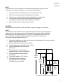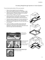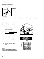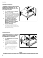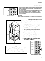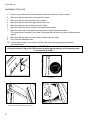
1
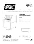
2000 Series
Installation/Operation Manual with Service Replacement Parts
For Champion Model DH2000 • Moyer Diebel Model MD2000 • International Model IDH2000
Door-type
High Temperature
Dishwasher
Model: 2000 Series
Hot water sanitizing machine w/fresh
water rinse and built-in stainless steel
electric booster
Machine Serial No.
Issue Date: 7.1.14
Manual P/N 114614 rev. L
For machines beginning with S/N D09037592 and above
3765 Champion Boulevard
Winston-Salem, NC 27105
336/661-1556 Fax: 336/661-1660
Toll-free: 800/ 858-4477
2674 N. Service Road, Jordan Station
Ontario, Canada L0R 1S0
905/562-4195 Fax: 905/562-4618
Toll-free: 800/ 263-5798
Printed in the USA
For future reference, record your dishwasher information in the box below.
Model Number__________________________ Serial Number_______________________
Voltage________________Hertz_____________ Phase__________________
Service Agent __________________________________ Tel:______________________
Parts Distributor _________________________________ Tel:______________________
National Service Department
In Canada:
Toll-free: 800/ 263-5798
Tel:
905/ 562-4195
Fax:
905/ 562-4618
email: [email protected]
In the USA:
Toll-free: 800/ 858-4477
Tel:
336/ 661-1556
Fax: 336/ 661-1660
email: [email protected]
ATTENTION:
The model no., serial no., voltage, Hz
and phase are needed to identify your
machine and to answer questions.
The machine data plate is located
on the top-mounted control cabinet.
Please have this information ready
if you call for service assistance.
The USGBC and the CaGBC Member Logos are trademarks owned by the U.S. Green Building Council and The Canadian Green Building Council,
respectively, and are used by permission. The logos signify only that Champion Industries and Moyer Diebel are USGBC members and CaGBC
members; USGBC and CaGBC do not review, certify nor endorse the products or services offered by its members.
COPYRIGHT © 2014 All rights reserved
Printed in the USA
REGISTER YOUR PRODUCT ONLINE
Make sure you are connected to the internet then enter the address below.
In the U.S.A
http://www.championindustries.com/register
In Canada
http://www.championindustries.com/canada/register
PRODUCT REGISTRATION
BY FAX
COMPLETE THIS FORM AND FAX TO:
(336) 661-1660 in the USA
1-(800) 204-0109 in Canada
PRODUCT REGISTRATION CARD
Serial #
Model
Date of Installation:
Company Name:
Address:
Telephone #: (
)
---
(Street)
Province
Postal Code
Contact:
Installation Company:
Address:
Telephone #:
Contact:
FAILURE TO REGISTER YOUR PRODUCT MAY VOID YOUR WARRANTY
IMPORTANT
IMPORTANT
Revision History

Revision History
The Revision History can contain part number changes, new instructions, or information that was
not available at print time. We reserve the right to make changes to these instructions without
notice and without incurring any liability by making the changes. Equipment owners may request
a revised manual, at no charge, by calling 1 (800) 858-4477 in the USA or by calling
1 (800) 263-5798 in Canada.
Revision
Date
6.12.09
Revised
Pages
All
Serial Number
Effectivity
D09037592
Revision
Description
Released First Edition
8.12.09
All
D09037592
Changed Schematic for Overlow tempering Ckt.
9.11.09
24-25
D09087829
Added 1/2" Piping to Fill Assy.
9.16.09
31-32
D09087829
Corrected P/N of Pump Suction
Screen to 333021
10.23.09
20-21
D09087829
Added 1/2" to Booster Piping
2.12.10
26-27
D09087829
Added Front and Side Panels
2.22.10
5
D09087829
Changed location of element
jumper bars
10.6.10
31
D09087829
Changed description of items
22, 23, 24
3.8.11
24-25
All
Added P/N 114861, Endcap
Item 37 to parts list
8.22.11
30-31
D10088521
Changed Item 2, P/N 114468 to
P/N 114745
6.1.12
36
D10088521
Revised Electrical Schematic
Drain Tempering Circuit
6.1.12
Use Kit 900962 to repair or
replace the final rinse arm
24-25
All
12.16.13
22-23
D130711000
Updated control cabinet cover
to square corners, P/N 335089
7.1.14
30-31
All
Float Switch Flat washer P/N
changed to 104882
i
Limited Warranty
LIMITED WARRANTY
Champion Industries Inc. (herein referred to as Champion), 3765 Champion Blvd., Winston-Salem, North Carolina 27105,
and P.O. Box 301, 2674 N. Service Road, Jordan Station, Canada, L0R 1S0, warrants machines, and parts,
as set out below.
Warranty of Machines: Champion warrants all new machines of its manufacture bearing the name "Champion" and installed within the United States and Canada to be free from defects in material and workman
ship for a period of one (1) year after the date of installation or fifteen (15) months after the date of shipment by
Champion, whichever occurs first. [See below for special provisions relating to glasswashers.] The warranty
registration card must be returned to Champion within ten (10) days after installation. If warranty card is not
returned to Champion within such period, the warranty will expire after one year from the date of shipment.
Champion will not assume any responsibility for extra costs for installation in any area where there are
jurisdictional problems with local trades or unions.
If a defect in workmanship or material is found to exist within the warranty period, Champion, at its election,
will either repair or replace the defective machine or accept return of the machine for full credit; provided;
however, as to glasswashers, Champion's obligation with respect to labor associated with any repairs shall end
(a) 120 days after shipment, or (b) 90 days after installation, whichever occurs first. In the event that Champion elects to repair, the labor and work to be performed in connection with the warranty shall be done during regular working hours by a Champion authorized service technician. Defective parts become the property of Champion. Use of replacement parts not authorized by Champion will relieve Champion of all further liability in connection with its warranty. In no event will Champion's warranty obligation exceed Champion's charge for the machine. The following are not covered by Champion's warranty:
a.
b.
c.
d.
e.
f.
g.
h.
i.
j.
Lighting of gas pilots or burners.
Cleaning of gas lines.
Replacement of fuses or resetting of overload breakers.
Adjustment of thermostats.
Adjustment of clutches.
Opening or closing of utility supply valves or switching of electrical supply current.
Cleaning of valves, strainers, screens, nozzles, or spray pipes.
Performance of regular maintenance and cleaning as outlined in operator’s guide.
Damages resulting from water conditions, accidents, alterations, improper use, abuse, tampering, improper installation, or failure to follow maintenance and operation procedures.
Wear on Pulper cutter blocks, pulse vanes, and auger brush.
Examples of the defects not covered by warranty include, but are not limited to: (1) Damage to the exterior or interior finish as a result of the above, (2) Use with utility service other than that designated on the rating plate, (3) Improper connection to utility service, (4) Inadequate or excessive water pressure, (5) Corrosion from
chemicals dispensed in excess of recommended concentrations, (6) Failure of electrical components due to
connection of chemical dispensing equipment installed by others, (7) Leaks or damage resulting from such
leaks caused by the installer, including those at machine table connections or by connection of chemical
dispensing equipment installed by others, (8) Failure to comply with local building codes, (9) Damage
caused by labor dispute.
Warranty of Parts: Champion warrants all new machine parts produced or authorized by Champion to be free from defects in material and workmanship for a period of 90 days from date of invoice. If any defect in
material and workmanship is found to exist within the warranty period Champion will replace the defective
part without charge.
DISCLAIMER OF WARRANTIES AND LIMITATIONS OF LIABILITY. CHAMPION'S WARRANTY IS ONLY TO THE EXTENT REFLECTED ABOVE. CHAMPION MAKES NO OTHER WARRANTIES, EXPRESS OR IMPLIED, INCLUDING,
BUT NOT LIMITED, TO ANY WARRANTY OF MERCHANTABILITY, OR FITNESS OF PURPOSE. CHAMPION SHALL
NOT BE LIABLE FOR INCIDENTAL OR CONSEQUENTIAL DAMAGES. THE REMEDIES SET OUT ABOVE ARE
THE EXCLUSIVE REMEDIES FOR ANY DEFECTS FOUND TO EXIST IN CHAMPION DISHWASHING MACHINES AND
CHAMPION PARTS, AND ALL OTHER REMEDIES ARE EXCLUDED, INCLUDING ANY LIABILITY FOR INCIDENTALS
OR CONSEQUENTIAL DAMAGES.
Champion does not authorize any other person, including persons who deal in Champion dishwashing machines
to change this warranty or create any other obligation in connection with Champion Dishwashing Machines.
ii
Table of Contents
_
Table of Contents
2000 Series Door-type Dishwasher
Revision History
............................................................................................................i
Limited Warranty
............................................................................................................ii
Model Descriptions ............................................................................................................iv
Installation...............................................................................................1
Receiving.....................................................................1
Electrical Connections.................................................2
1 phase to 3 phase Conversion.......................5
Hot Water and Drain Connections...............................6
Vent Fan and Chemical Dispensers............................7
Initial Start-up...........................................................................................7
Installation Check List..................................................8
Operation................................................................................................................. 9
Normal Wash Mode.....................................................9
Rinse Sentry Mode......................................................11
Automatic Drain Cycle.................................................11
Cleaning and Maintenance.........................................................................12
Cleaning.......................................................................12
De-liming......................................................................14
Maintenance................................................................15
Troubleshooting...........................................................16
Service Replacement Parts........................................................................17
Timer Chart..............................................................................................35
Electrical Schematic.............................................................................................. 36
iii
Model Description
Model Description
2000 Series
High temperature hot water sanitizing dishwasher with
built-in 40-70°F/22-82°C rise booster heater.
Field convertible single or three phase
Self-draining pump
Automatic start
Fresh water rinse
55 racks per hour/60-second total cycle time
Rinse sentry
Automatic drain valve
Optional Equipment (consult factory)
Drain water tempering kit
Side panels
iv
Installation
Receiving
NOTE:
The installation of your dishwasher must be performed by qualified service personnel.
Problems due to improper installation are not covered by the Warranty.
1.
Inspect the outside of the dishwasher carton for signs of damage.
2.
Remove the carton and inspect the dishwasher for damage.
3.
Check for any accessories that may have shipped with your dishwasher.
4.
Turn to the front of this manual and complete the warranty card.
Immediately mail the warranty card to validate your warranty.
5.
Move the dishwasher near its permanent location.
CAUTION:
Be careful when lifting and moving the dishwasher to prevent damage to the machine.
NOTE:
The installation of the dishwasher must comply with all local electrical, plumbing, health and
safety codes or in the absence of local codes, installed in accordance with the applicable
requirements in the National Electrical Code, NFPA 70, Canadian Electrical Code (CEC),
Part 1, CSA C22.1; and the Standard for Ventilation Control and Fire Protection of
Commercial Cooking Operations, NFPA 96.
6.
Compare the installation site utility connections with the dishwasher utility connections and
make sure that they are the same.
7.
Place the dishwasher in its permanent location.
8.
The dishwasher has 4 adjustable feet for leveling.
9.
Level the dishwasher front-to-back and
side-to-side.
10. The dishwasher can be installed in a
straight-through or a corner configuration.
11. The typical dishwasher load height is
33¾" [86cm].
12. The machine height is 65¼" [166cm].
13. The dishwasher doors require an
open height of 76¾" [195cm] and
86" [218cm] for door removal.
86"
[218cm]
Door
Removal
Ht.
76¾"
[195cm]
17¼"
[44cm]
Inside
Clearance
Door Up
Ht.
65¼"
[166cm]
Machine
Ht.
33¾"
[86cm]
Load
Ht.
26⅛"
[66cm]
Dishwasher Dimensions in inches and Centimeters
1
Installation
Converting Straight-through Operation to Corner Operation
Dishwashers are shipped from the factory for Straight-through operation. Refer to the diagrams below
and on the next page to convert a Straight-through operation machine to a Corner operation machine.
Dish racks enter and exit the sides of a straight-through machine. Dish racks enter the side and exit the
front of corner operation machine.
To convert the dishwasher:
1.
Convert the dishwasher before it is placed in its final position and before connecting utilities.
2.
The temperature gauges must be clearly visible to the operator when facing the front of the
machine. In addition, the door handles should move freely without interference from walls or other
obstructions. Nominal wall clearance is 6" [152mm]; the minimum wall clearance is 4" [102mm].
3.
Position the dishwasher as shown below and refer to the next page for instructions on changing
the dish rack guides and door operation.
Temp.
Gauges
Temp.
Gauges
6" [15cm]
Correct Orientation for
Straight-Through Operation
Incorrect Orientation for
Corner Operation
Temp.
Gauges
6" [15cm]
Correct Orientation for
Corner Operation
2
6" [15cm]
Installation
Converting Straight-through Operation to Corner Operation
To convert track guides and door-lift for corner operation:
1.
Remove the rack guide (A); save the fasteners.
Move (A) and re-attach as shown in the illustration at right.
2.
Slide a dish rack through the machine to check the guide to
dish rack clearance. The dish rack should move smoothly
without binding or tipping on the guides.
3.
Disconnect the door-lift bracket (B) connecting the front door
and the wall-side door and discard. To seal the holes,
Re-install the bolts and lockwashers that held the bracket.
4.
Disconnect the door linkage arm (C) from the wall-side door
and discard. Re-install the white roller (D) and hardware.
5.
Disconnect the door linkage arm (C) from the other door but
do not discard.
6.
Lift the door handle up and back until the springs relax.
7.
Adjust the door spring hooks (E) located at the rear of
dishwasher to reduce door spring tension until the front and
side doors open and close without binding.
A
Remove the door-lift
bracket connecting the
front and wall-side
doors.
wa
ll
wa
B
Remove the door-linkage
arm from the wall-side
door and discard.
ll
A
Re-install the white roller
with existing hardware.
C
D
Re-adjust the door springs at the rear of the
dishwasher then check that the doors open
and close without binding.
E
3
Installation
Electrical Connections
Three Phase Operation
WARNING:
Electrocution or serious injury may result when working on an
energized circuit.
Disconnect power at the main breaker or service disconnect
switch before working on the circuit.
Lock-out and tag the breaker to indicate that work is being
performed on the circuit.
ATTENTION
A qualified electrician must connect the main incoming power to the dishwasher in accordance with all
local codes and regulations or in the absence of local codes in accordance with the National Electrical
Code.
Standard Dishwashers are shipped from
the factory for 3-phase operation.
To connect the dishwasher for 3-phase
operation:
1. Remove the top-mounted control
cabinet cover and locate the main
terminal block in the left-rear
corner of the cabinet.
2.
3.
4.
Refer to the Machine Electrical
Connection Data Plate located
near the main terminal block and
make sure that the incoming
power supply matches the
machine's electrical requirements.
Connect the incoming 3-phase
power as shown in the illustration
to the right.
Re-install the control cabinet
cover.
NOTE:
Refer to the next page for 3-phase to
1-phase field conversion instructions.
4
Main Terminal Block
Main Terminal Block Location
THREE PHASE
POWER CONNECTION
208-240V/60/3
LINE IN
L1
GRD
L2
L3
Installation
Electrical Connections
Field Conversion from 3-phase to 1-phase Operation
SINGLE PHASE
POWER CONNECTION
208-240V/60/1
A standard 3-phase operation dishwasher can be converted for
1-phase operation with the installation of a jumper wire on the main
terminal and rewiring of the wash tank and booster tank heaters.
A jumper wire, jumper bars and a new data plate are stowed
on top of the wash tank heater junction box.
To convert the dishwasher from 3-phase to 1-phase operation:
LINE IN
GRD
Install Main Terminal Block Jumper Wire
L1
L2
1. Disconnect all power to the machine.
2. Remove the top-mounted control cabinet cover and locate the
main terminal block located in the left-rear corner of the cabinet.
3. Connect the jumper wire (shipped inside the control cabinet)
between L2 and L3 on the output side of the main terminal block.
L1
4. Connect the 1-phase incoming power supply to L1 and L2 on the
input side of the main terminal block.
L3
JUMPER
Connect the jumper wire between L2 and L3
on the output side of the main terminal block
Rewire Wash Tank Heater Element for 1PH
1. Remove the lower front panel.
L1
2. Remove the wash tank heater junction box cover.
33
3. Remove the paper insulator and jumper bars from the heater
terminals.
34
4. Additional short jumper bars are stowed with the new data plate.
L2
L1
L2
3PH
33
L3
L2
35
5. Reposition the jumper bars for 1PH as shown below.
1PH
6. Connect the #33 wire to one element terminal as shown.
7. Connect the #34 and #35 wires to the other terminals as shown.
L3
34
35
8. Reinstall the paper insulator and the junction box cover.
3PH
Rewire Booster Heater Element for 1PH
L3
38
1PH
1. Remove the booster heater element cover.
2. Remove the paper insulator and jumper bars from the heater
terminals.
3. Install the jumper bars for 1PH as shown below.
4. Additional short jumper bars are stowed with the new data plate.
5. Connect the #36 wire to one element terminal as shown.
6. Connect the #37 and #38 wires to the other terminals as shown.
7. Reinstall the paper insulator and the booster heater element cover.
37
L2
36
L1
38
L3
36
37 L1
L2
NOTE: The additional jumper bars needed
for 1PH operation are stowed with the new
data plate on top of the wash tank heater
junction box.
ATTENTION:
Affix the new data plate on top of the existing machine data plate to complete the conversion.
5
Installation
Hot Water Connection
The hot water connection is located at the lower
left-rear side of the dishwasher. A 3/4" line
strainer and pressure regulating valve (PRV)
were installed at the factory.
1.
The size of the incoming hot water line
should be 3/4" or larger.
2.
The PRV should be adjusted to supply a
minimum flowing pressure of 20 PSI/138
kPA during the final rinse. The maximum
flowing pressure must not exceed 25
PSI/172 kPa during the final rinse.
3.
The temperature of the incoming
hot water must maintain a minimum
temperature of 140°F/60°C for a
40°F/22°C rise booster or a minimum
temperature of 110°F/43°C for a
70°F/39°C rise booster.
4.
The incoming hot water line is a 3/4" NPT connection.
A manually operated 3/4" or larger
shut-off valve should be installed in the
incoming line as close to the dishwasher
as possible for servicing.
Drain Connection
The drain water connection is a 2" slip-fit hose
connection and is located at the center-rear of
the machine base. It is a gravity drain.
1.
The dishwasher drain is 2" O.D. hose
connection.
2.
A optional drain water tempering kit
is available (consult the factory).
3.
Drain water flow is controlled by an
automatic electrically operated drain
valve.
4.
The floor sink and/or drain plumbing
must be able to accommodate a
maximum drain flow rate of
20 US gpm / 17 Imp gpm / 76 Lpm.
The drain is a 2" slip-fit hose connection.
NOTE:
Plumbing connections must comply with all national and/or local plumbing and sanitary codes.
6
Installation
Vent Fan Control
SIGNAL ONLY
VENT FAN
120V
COMMON
The Vent Fan Control Signal is limited to
RINSE AID
120VAC 1 Amp maximum load.
120V
1. A vent fan control signal is provided on a terminal block located
inside the top-mounted control cabinet. The terminal locations
are clearly marked.
2. The 120VAC signal is designed only to operate an external vent
fan contactor (supplied by others) and is limited to 1 AMP
maximum load and is available when the dishwasher power
switch is turned ON.
CAUTION:
Do not connect a vent fan motor to the signal connection terminals.
Chemical Dispenser Provisions
COMMON
Provisions for chemical suppliers to connect their
chemical dispensing systems are provided on the
dishwasher and include:
DETERGENT
120V
Rinse-aid
1.
A 1/4" NPT plastic fitting as a rinse-aid injection
point. The fitting is installed in the upper final
rinse piping located at the top-rear of the
dishwasher (see illustration at left).
2.
Two 7/8" holes are provided on the right-side
rear of the wash tank as detergent injection
points.
3.
Detergent and rinse-aid control signals are
available inside the top-mounted control
cabinet. The signals are 120VAC, Max. 1 Amp
load. Connection points are located on a
labeled terminal block (see below).
4.
DO NOT REMOVE THE JUMPER BETWEEN
THE COMMON TERMINALS.
Detergent
SIGNAL ONLY
Detergent and Rinse-aid Injection Points
VENT FAN
120V
COMMON
RINSE AID
120V
COMMON
A commercial grade non-chlorinated detergent
is recommended for use with this machine.
JUMPER
NOTE:
Consult a qualified chemical supplier for chemical
supplies and chemical dispensing equipment.
DETERGENT
120V
DO NOT REMOVE THE JUMPER
BETWEEN THE COMMON TERMINALS
7
Initial Start-up
Installation Check List
1.
Remove any protective film from dishwasher. Check the interior for foreign material.
2.
Make sure that the dishwasher is permanently located.
3.
Make sure that all utility connections are complete.
4.
Make sure that the chemical supply containers are full.
5.
Make sure that the pump suction screen is in place.
6.
Make sure the drain screen is clean and unobstructed by debris.
7.
Make sure the scrap screen plate and scrap screens installed and firmly seated.
The screen plate is mounted in the center of the wash tank and locks in a slot on the back screen
support.
8.
Make sure that the spray arms are in place and that they spin freely.
9.
Fully close the dishwasher door.
10. Turn hot water supply on and check for leaks in the main water supply piping connected
to the dishwasher.
IMPORTANT
During the initial fill, adjust the PRV to ensure that the flowing pressure of the incoming water
is set between 20-25 PSI.
Make sure the pump suction strainer is in place.
Make sure the scrap screen plate is mounted in the center
of the wash tank and separating the scrap screens.
8
Make sure the drain screen is
unobstructed.
Make sure the scrap screens are in place.
Operation
Normal Operation Mode
Door Safety
Switch
Power
Switch
Wash
Temperature
Gauge
Final Rinse
Temperature
Gauge
Pressure
Gauge
In-cycle
Light
Follow the instructions below to operate the dishwasher in a Normal Wash Mode. A Rinse Sentry feature
holds the dishwasher in a wash mode if the booster heater temperature is below 180ºF/82ºC.
1.
Turn the main power on at the main circuit breaker.
2.
Make sure the spray arms and the scrap screens are in place.
3.
Turn the water supply on.
4.
Close the dishwasher front door.
5.
Push the dishwasher Power Switch to the ON position. The power switch will illuminate and the
machine will fill with water.
6.
Check the pressure gauge as the machine fills and make sure the incoming water pressure is
between 20-25 psi.
7.
Wait up to 10-minutes for the WASH temperature gauge to indicate a minimum of 150ºF/66ºC.
8.
Load soiled wares into the dish rack. Place plates, glasses, cups and bowls in a peg rack.
Place utensils in a single layer in a flat-bottom rack. Place pots and pans in a flat-bottom rack.
Do not overload the dish racks.
9.
Slide 1 dish rack into the wash compartment making sure that wares do not interfere with the
rotating spray arms. Do not wash more than 1 dish rack at a time.
10. Close the front door fully, the wash cycle will begin automatically. The green
in-cycle light will illuminate.
11. The wash cycle time runs for approximately 40-seconds. (continued on next page)
9
Operation
Normal Operation Mode (continued)
12. Opening the door when the dishwasher is in-cycle will stop the dishwasher. The cycle will resume
automatically when the dishwasher door is closed.
13. The final rinse cycle begins at the end of the wash cycle and runs for approximately 12-seconds.
14. Check the FINAL RINSE temperature gauge during the final rinse and make sure that it indicates a
minimum of 180ºF/82ºC. The acceptable range of operation is 180-195ºF/82-91ºC.
15. Check the pressure gauge located at the top of the dishwasher to ensure that the final rinse
pressure maintains a flowing pressure between 20-25 PSI.
16. At the end of the rinse cycle, the in-cycle light will go out. Open the door and remove the clean
rack of wares. Repeat steps 8-15 for additional dish racks.
17. Refer to the Automatic Drain Cycle on the next page for the procedures to drain the dishwasher.
150°F/66°C
Final Rinse
Pressure
20
0
22
Wash
Temperature
80
0
20
60
80
100
200
100
60
60
20
140
180
CHAMPION INDUSTRIES, INC.
WINSTON-SALEM,NC
0
80
40
40
0
50
10
60
180
20
40
PSI
60
80
40
120
100
160
40
140
160
30
20
120
100
180-195°F
82-91°C
200
20-25 PSI
0
22
Final Rinse
Temperature
The pressure gauge is located at the top of the dishwasher. The wash temperature gauge and
the final rinse temperature gauges are located on the front of the control cabinet.
10
Operation
Rinse Sentry Operation Mode
The final rinse water temperature must be a minimum of 180ºF/82ºC during the final rinse cycle to ensure
that all wares are sanitized. If for any reason, the hot water temperature in the booster tank cannot provide
this temperature, the dishwasher will enter a Rinse Sentry Mode of operation and extend the cycle time.
The Rinse Sentry changes the Normal Operation Mode as described below:
1.
The Rinse Sentry constantly monitors the water temperature inside final rinse booster.
2.
If the temperature inside the booster heater falls below 180ºF/82ºC then the Rinse Sentry
will extend the wash cycle time until the booster heater water temperature reaches the proper
temperature.
3.
The in-cycle light will remain illuminated during the Rinse Sentry Mode.
4.
The RINSE water temperature gauge must be monitored to ensure that a minimum of
180ºF/82ºC is maintained during the rinse cycle.
5.
The temperature range for the final rinse water is 180-195ºF/82-91ºC.
6.
An extraordinarily long wash cycle may indicate a low incoming water temperature or a
problem with the booster heater operation.
DO NOT REMOVE WARES UNTIL THE FINAL RINSE CYCLE HAS
SANITIZED THE WARES AND THE GREEN CYCLE LIGHT GOES OUT.
Automatic Drain Cycle
The dishwasher can be drained automatically when the dishwasher has completed a normal wash cycle
or whenever the dishwasher is idle.
To drain the dishwasher:
1.
Turn the dishwasher Power Switch OFF. The automatic drain valve will open and the machine
will drain.
2.
The drain valve will remain open for 10-minutes to allow time to flush the interior with fresh water
during a cleaning operation.
3.
When 10-minutes has elapsed the drain, the drain valve will close.
The automatic drain cycle is complete.
NOTE:
The automatic drain cycle can be repeated after 10-minutes by turning the power Switch ON and
immediately OFF. The dishwasher will drain for another 10-minutes and then turn off.
11
Cleaning and Maintenance
Cleaning
After Each Meal Period or every 8 Hours of Operation.
1.
Press the lighted power switch to the OFF position. The power switch light will go out
and the automatic drain cycle will operate for 10-minutes.
2.
Flush the interior of the machine with fresh water.
3.
Remove the scrap screens and remove debris in a waste container.
4.
Flush the scrap screens making sure to back-flush.
5.
Do not strike the scrap screens against solid objects.
6.
Flush the wash tank, the pump suction strainer and drain screen.
7.
Check the wash tank for foreign material and clean as required.
8.
Replace pump suction strainer and scrap screens.
9.
Make sure that spray arms turn freely.
10. Check the chemical containers and refill as required.
11. Close the door and turn the power switch ON. The machine will refill with fresh hot water.
12. Resume normal operation.
Clean scrap screens.
Clean drain screen.
12
Clean pump suction strainer
Cleaning and Maintenance
Cleaning
At the End of the Day
1.
Perform Steps 1-10 on the previous page.
2.
Remove the upper and lower rinse and wash spray arms. The spray arms are interchangeable.
3.
Unscrew the upper and lower rinse arm spindles (A). Remove the rinse arm assemblies
4.
Clean the final rinse arm nozzles using a small paper clip (B).
5.
Remove the rinse arm end plugs (C) if necessary, and flush the rinse arm with clean water.
6.
Re-install the rinse arm end plugs if they were removed.
7.
Remove the wash spray arms and flush with clean water.
8.
DO NOT USE STEEL WOOL TO CLEAN THE INTERIOR OF THE MACHINE.
9.
Contact the chemical supplier for de-liming if required (see next page).
10. Wipe the interior and exterior of the machine with a soft cloth and a mild detergent.
DO NOT HOSE THE EXTERIOR OF THE MACHINE WITH WATER.
11. Reassemble the dishwasher and leave the door open to allow overnight drying.
Paper Clip
B
End
Plug
C
Rinse Arm Spindle
A
Wash Spray arm
D
13
Cleaning and Maintenance
De-liming
Minerals accumulate on the interior surfaces of the dishwasher. The deposits have a white haze
and, in cases of heavy accumulation, may appear as a granular solid. The generic name for mineral
deposits is lime. The removal of lime deposits is called de-liming. Your dishwasher should be
de-limed regularly; how often will depend on the mineral content of your water.
Inspect your machine interior for lime deposits. If de-liming is required, a de-liming agent should be
used for best results in accordance with the chemical supplier's instructions.
Danger:
Death or serious injury may result when de-liming solution is mixed with sodium hypochlorite
(chlorine bleach) sanitizing agent. Mixing may cause hazardous gases to form.
De-liming solution and other acids must never be mixed with chlorine, iodine, bromine, or fluorine.
CAUTION:
Skin contact with de-liming solutions can cause severe irritation and possible chemical burns.
Always wear protective clothing and goggles when handling chemicals.
Attention:
Contact your chemical supplier for specific safety procedures and instructions for the use of
the de-liming solution supplied for the dishwasher.
De-liming solution or other chemicals are not supplied by the dishwasher manufacturer.
14
Cleaning and Maintenance
Maintenance
Daily Maintenance
1.
Check all of the wash arm and rinse arm spray jets and clean as necessary.
2.
Make sure the water supply is on and that the drain is not clogged.
3.
Check the temperature gauges and/or displays to ensure that they are operating.
4.
Make sure dish racks are in good condition.
5.
Check the chemical containers and refill as required.
6.
Follow the cleaning procedures given above.
Weekly Maintenance
1. Perform Steps 1-5 in the Daily Maintenance.
2. Inspect water lines for leaks.
3. Check for water leaks underneath the dishwasher.
4. Make sure the floor drain and/or piping handles the drain water discharge.
5. Make sure the dishwasher is level.
6. Clean accumulated lime deposits from the wash tank heating element.
7. Inspect the scrap screen and replace it if damaged.
8. Check the spray arms and replace or repair if damaged.
NOTE:
Consult your chemical supplier for chemical dispensing system maintenance.
15
Troubleshooting
Follow the troubleshooting guide below in the event that your dishwasher does not operate as
expected. Perform the basic checks below before calling an authorized service agent:
1.
Make sure that the main water supply is turned on.
2.
Make sure that the main power is turned on.
3.
Make sure the machine is clean.
Condition
Cause
Solution
Dishwasher will not run.
Door not closed.
Main power OFF.
Dishwasher OFF.
Close door completely.
Check breaker on panel.
Turn dishwasher ON.
Low or no water.
Main water supply off.
PRV setting incorrect
Line strainer clogged.
Solenoid valve defective.
Open supply valve.
Adjust the PRV setting
Contact Service Agent.
Contact Service Agent.
Chemicals won’t feed into
dishwasher.
Chemical supply low.
Pick-up tube clogged
Supply tubing damaged.
Supply tubing kinked.
Refill chemical container.
Clean/replace tube.
Replace tubing.
Straighten tubing.
Poor wash results.
Wares incorrectly loaded.
in dishrack.
Reposition wares or
reduce amount of wares.
Clogged screens.
Clogged spray arms.
Clean screens.
Clean spray arms.
Chemical injectors not
feeding.
Contact Chemical Supplier.
Thermostat defective.
Contact Service Agent.
Detergent motor defective.
Contact Service Agent
Water temperature low.
Contact Service Agent
Dishwasher stays in
wash cycle.
Rinse Sentry extends wash Contact Service Agent.
mode to allow final rinse
water booster temperature
to reach 180˚F/82˚C.
Dishwasher will not drain.
Drain screen clogged.
Clean drain screen.
Drain valve defective.
Contact Service Agent.
16
Service Replacement Parts
Service Replacement Parts
IllustrationsPage
Wash Pump/Motor Assembly ................................................................................................................................. 18
Booster Assembly.................................................................................................................................................... 20
Control Panel Assembly.......................................................................................................................................... 22
Wash and Rinse Spray Arm Assemblies................................................................................................................. 24
Hood and Door Assembly........................................................................................................................................ 26
Track Assembly....................................................................................................................................................... 28
Wash Tank Heat, Drain, Screens, Hoses................................................................................................................ 30
Dish racks, Line Strainer and Pressure Regulating Vavle (PRV)............................................................................ 32
Timer Chart ............................................................................................................................................................. 35
Electrical Schematics.............................................................................................................................................. 36
17
Wash Pump/Motor Assembly
13
6
5
4
1
7
8
9
10
11
14
12
2
3
18
Wash Pump/Motor Assembly
ItemPart
No.No.
Description
1
SLINGER, WATER
1
2114135
NUT
9
3114136
SCREW
9
4
114137
BACKPLATE, PUMP
1
5
114138
GASKET, PUMP
1
6
114139
SEAL, PUMP
1
7114140
WASHER
1
8114141
IMPELLER
1
9114142
WASHER
1
10
114143
WASHER, LOCK
1
11
114144
NUT, IMPELLER
1
12
114145
HOUSING, PUMP
1
13
114322
CAPACITOR 15μF
1
PUMP/MOTOR ASSEMBLY COMPLETE
220VAC/60/1
1
114134
14
114525
Qty.
NOTE:
THE MOTOR CANNOT BE ORDERED AS A SEPARATE REPLACEMENT PART.
19
Booster Assembly
11
5
15
4
13
1
12
21 7
17
3
20
19
18
10
7
8
7
16
9
14
6
20
22
2
Booster Assembly
ItemPart
No.No.
Description
Qty.
1
100184
NIPPLE, 3/4" NPT X CLOSE BRASS
2
2
100210
PLUG, 1/8" SST
1
3
100571
UNION, 3/4" NPT BRASS
1
4
102444
ELBOW, STREET 3/4" NPT X 90° BRASS
2
5
107550
VALVE, PRESSURE REG. 3/4" NPT BRASS
1
6
107908
COVER, HEATER
1
7
107966
NUT, HEX GRIP 10-32 SST W/NYLON
7
8
109069
THERMOSTAT, W/CAPILLARY
1
9
109985
O-RING, BOOSTER HEATER
1
10
110562
THERMOSTAT, HI-LIMIT FIXED SNAP 240°F
1
11
110768
STRAINER, LINE 3/4" BRONZE FEMALE
1
12 110929
BOX, ELECTRIC BOOSTER, THERMOSTAT
1
13
110930
COVER, BOOSTER THERMO BOX
1
14
111233
15
111437
HEATER, BOOSTER 7.5kW/10kW,
208-240V, 1 & 3 PH
1
VALVE, SOLENOID 120VAC 3/4" NPT
1
---
108516
COIL, SOLENOID 120VAC
A/R
---
109903
KIT, REPAIR SOLENOID VALVE 3/4"
A/R
16
0509042
TANK, BOOSTER WELDMENT
1
17
0512027
BARB,HOSE 3/4" NPTx3/4"BR (Before S/N D090878291
---
108528
BARB, HOSE 1/2" NPT BR (After S/N D09087829)
1
18
B500355
CONNECTOR, STRAIN RELIEF CORD
1
19
113269
CLAMP, HOSE
1
20
206727
HOSE, 3/4" (Before S/N D09087829) 1
---
206987
HOSE, 1/2" (After S/N D09087829)
21
333154
BRACKET, PIPING SUPPORT
1
22
111488
JUMPER, STRIP (spares used for conversion)
3
21
Control Panel Assembly
26
2
21
48
31
32
22
47
37
33
28
4
35
27
25
46
5
20
43
6
11
8
18
41
10
30
9
36
45
1
49
22
23
51
42
39
34
40
50
44
Control Panel Assembly
ItemPart
No.No.
1
2
3
4
5
6
7
8
9
10
11
12
13
14
15
16
17
18
19
20
21
22
23
24
25
26
27
28
29
30
31
32
33
34
35
36
37
38
39
40
41
42
43
44
45
46
47
48
---
49
50
51
100003
100007
100100
100736
100929
103310
104873
106026
106364
106402
106925
106975
106976
106977
106980
107098
107099
107289
107564
107964
108122
108397
109849
110574
110836
110838
111036
111068
111319
111331
111628
111702
111833
112086
112519
112614
113314
113506
113622
113644
113721
114236
114470
114583
114584
206015
206016
331602
335089
331693
332545
0512220
Description
NUT, HEX PLAIN 1/4-20 SST
SCREW, TRUSS HD. 10-32 X 3/8" SST
SCREW, ROUND HD. 8-32 X 1/4" SST
BOLT, HEX HD., 1/4-20 X 3/4" SST
FUSE, ATMR-30, 600V ONE-TIME
LUG, GROUND
LABEL, GROUND
WASHER, FLAT 1/4" SST
LIGHT, INDICATOR
FUSE BLOCK, 2-POLE
FUSE BLOCK, 3-POLE
LABEL, 1CR
LABEL, 2CR
LABEL, 3CR
LABEL, 1M
LABEL, XFMR
LABEL, 1MOL
FUSE, 2.5 A
SCREW, TRUSS HD. 6-32 X 1" SST
PLUG, SNAP
CONTACTOR, 3-POLE
TRANSFORMER, 150VA
INSULATION, CONTROL CABINET
LABEL, MAX AMP
FITTING, STRAIGHT, 1/2" SEALTITE
FITTING, STRAIGHT, 3/4" SEALTITE
SOCKET, RELAY 2-POLE
RELAY, 2-POLE, 10 AMP
SCREW, TRUSS HD. 6-32 X 1/2" SST
TERMINAL STRIP, 8-POLE
MOTOR STARTER
CONTACTOR, 3-POLE
TERMINAL BLOCK, INPUT
OVERLAY, 150°F, WASH
PLUG, SNAP
LABEL, VENT FAN SIGNAL
TIMER, INFITEC, 600SEC
LABEL, MAX AMP
GAUGE, RINSE, TEMPERATURE, 4FT. CAPILLARY
OVERLAY, 180°F, RINSE
SWITCH, REED ALEPH
GAUGE, WASH, TEMPERATURE 8FT. CAPILLARY
CONTROL BD., ELECTRONIC
DECAL CHAMPION DH2000, CONTROL CABINET
DECAL MOYER DIEBEL MD2000, CONTROL CABINET
RAIL, DIN 35MM X 15MM
RAIL, DIN 35MM X 15MM
COVER, CONTROL CABINET, ROUND (Prior to S/N D130711000)
COVER, CONTROL CABINET, SQUARE (S/N D130711000 & ABOVE)
PANEL, INNER WRAP, CONTROL CABINET
SWITCH, ROCKER ON/OFF
Qty.
8
5
19
4
3
1
1
4
1
1
1
1
1
1
1
1
1
1
1
1
1
1
1
1
3
3
4
1
1
2
1
1
2
1
1
2
1
1
1
1
1
1
1
A/R
A/R
1
1
1
1
1
23
Wash and Rinse Spray Arm Assemblies
1
6
14
8
9
7
8
10
32
12
3
19
13
2
3
4
11
23
34
22
20
35
37
5
18
26
18
37
27
21
15
28
25
29
33
31
16
24
17
24
30
Wash and Rinse Spray Arm Assemblies
ItemPart
No.No.
Description
Qty.
1
2
3
4
5
6
7
---
8
---
9
---
---
10
11
12
13
14
15
16
17
18*
19
20*
21
22
23
24
25
26*
27
28
29
30
31
32
---
33
34
35
---
36
37
100135
100156
100171
100599 100736
102388
102525
102514
102651
100206
104429
100500
900837
107463
107967
108181
108620
109765
109835
109854
109864
113514
113622
114555
114556
332489
332552
332553
332761
332762
100740
102376
106013
0507443
0507446
0512027
107419
100154
113269
206727
206987
100171
114861
GAUGE, PRESSURE 0-60 PSI
1
LOCKNUT, 3/4" NPT BRASS
1
BUSHING, RED. FACE 3/4" X 1/2" BRASS
3
CROSS, 3/4" NPT BRASS
1
BOLT, HEX HD. 1/4-20 X 3/4" SST
2
BUSHING, RED 1/2" NPT X 1/4" NPT BRASS
1
TEE, RED. 3/4" X 1/2" X 3/4" NPT BRASS (Before S/N D09087829)1
TEE, 1/2" X 1/2" X 1/2" NPT BRASS (After S/N D09087829)
NIPPLE, 3/4" NPT X 2" LG. BRASS (Before S/N D09087829)2
NIPPLE, 1/2" NPT, 2-1/2" LG. BRASS (After S/N D09087829)
BREAKER, VACUUM 3/4" NPT BRASS (Before S/N D09087829)1
BREAKER, VACUUM 1/2" NPT BRASS (After S/N D09087829)
KIT REPAIR, 3/4" VACUUM BREAKER
A/R
PLUG, 1/4" NPT
1
HEX GRIP NUT, 1/4-20 SST W/NYLON
2
BUSHING, RED. 3/4" X 1/4" PVC
1
GASKET, RINSE MANIFOLD 3/4" PIPING
1
OVERLAY, PRESSURE GAUGE
1
SCREW, #8 X 1/2" PHILS. SST
4
GASKET, WASH STANDPIPE
1
SUPPORT, WASHARM HUB
1
BEARING, RINSE ARM
4
THERMOMETER, 8 FT. CAPILLARY
1
SPINDLE, RINSE ARM
2
NUT, RINSE ARM
2
STANDPIPE, WASH WELDMENT
1
SUPPORT, BRACKET
1
MANIFOLD, WELDMENT RINSE STANDPIPE
1
WELDMENT, WASHARM
1
WELDMENT, RINSE ARM
1
BOLT, HEX HD. 5/16-18 X 1" SST
4
WASHER, FLAT 5/16" SST
8
WASHER, LOCK SPLIT 5/16" SST
4
SPINDLE, WASH ARM
2
BEARING, WASH ARM SUPPORT
2
BARB, HOSE, ST 3/4" NPT X 3/4" H BRASS (Before S/N D09087829) 1
BARB, HOSE, ST 1/2" NPT X 1/2" H BRASS (After S/N D09087829) 1
NUT, HEX HD. PLAIN 5/16-18 SST
4
CLAMP, HOSE
1
HOSE, 3/4"
1
HOSE, 1/2"
1
BUSHING, FACE 3/4" X 1/2" NPT BRASS (After S/N D09087829)
2
ENDCAP, HEADLESS 7/16-20 SST
4
----
----
900926
900962
WASH ARM ASSY. COMPLETE (includes items 15, 25 and 31)
RINSE ARM ASSY. COMPLETE (includes items 18,20,21,26,37) 2
2
*Note: For machines built prior to S/N D12049848 you must order P/N 900962 to repair the
existing rinse arm assembly.
25
Hood and Door Assembly
11 20
2
4
11 25 12
21
16
20
4
13
6
7
9
17
13
15
10
10
24
14
4
3
23
8
1
21
5
27
6
3
4
29
24 19
27
28
29
29
26
18
22
26
Hood and Door Assembly
ItemPart
No.No.
Description
Qty.
1
100002
BOLT, HEX HD., 1/4-20 X 1-3/8" SST
2
2
100738
BOLT, HEX HD., 1/4-20 X 1" SST
4
3
106014
NUT, HEX ACORN PLAIN, 1/4-20 SST
4
4
106026
WASHER, FLAT 1/4" SST
21
5
107962
HANDLE, GRIP
2
6
107967
HEX, GRIP NUT, 1/4-20 SST W/NYLON
12
7
108954
HEX, GRIP NUT, 6-32 SST W/NYLON
2
8
113745
PLUG, HOLE FDA, SILICON
4
9
113937
MAGNET, ALEPH
1
10
114154
SCREW, TRUSS HD., 1/4-20 X 1/2" SST
6
11
0310781-1
PIVOT, DOOR HANDLE
4
12
0310792-1
PLATE, DOOR PIVOT
2
13
0310843-2
WEAR STRIP, DOOR 24" LG.
6
14
332538
HOOD, WELDMENT
1
15
332546
DOOR, LH
1
16
332547
DOOR, RH
1
17
332557
DOOR, FRONT
1
18
332867
BRACKET, CONNECTION DOOR
2
19
332881
LIFT BAR, DOOR
2
20
0510459
SPRING, DOOR
2
21
0510779-1
HANDLE, DOOR
1
22
0510787-1
SPACER, LIFT BAR, DOOR
1
23
0510788-1
TUBE, SPACER
2
24
0510788-2
TUBE, SPACER
4
25
0510791-1
GASKET, DOOR PIVOT
2
26
104618
WASHER, FLAT 3/8" SST
6
27
332559
PANEL, SIDE
2
28
332540
PANEL, FRONT
1
29
104923
SCREW, 1/4-20 X 3/8" RD., HD., SST
6
27
Track Assemby
3
7
11
6
9
4
8
10
1
28
5
2
Track Assembly
ItemPart
No.No.
Description
Qty.
1
100003
HEX PLAIN NUT, 1/4-20 SST
6
2
100073
SCREW, TRUSS HD., 1/4-20 X 1/2" SST
6
3
100754
SCREW, FLAT HD., 10-32 X 1/2" SST
2
4
104985
HEX PLAIN NUT, 10-32 SST
2
5
106482
WASHER, LOCK 1/4" SPLIT SST
6
6
106486
WASHER, LOCK #10 SPLIT, SST
2
7
332021
TRACK, REAR
1
8
332022
TRACK, FRONT
1
9
332023
TRACK, RAIL ADJUST
1
10
332024
BAFFLE, SPLASH
2
11
332025
TUBE, CROSS TRACK
1
29
Wash Tank Heat, Drain, Screens, Hoses
24
23
22
21
20
19
1
2
18
1
3
3
4
9
17 16
7
8
1
5
14
10
13
11
25
10
6
12
1
30
15
16
Wash Tank Heat, Drain, Screens, Hoses
ItemPart
No.No.
Description
Qty.
1
107340
CLAMP, HOSE
4
2
114745
HOSE, DISCHARGE
1
3
104203
CLAMP, HOSE
2
4
114467
HOSE, SUCTION
1
5
332543
COVER, JUNCTION BOX
1
6
114472
HOSE, OVERFLOW
1
7
304816
STRAINER, DRAIN
1
8
107967
HEX, GRIP NUT 1/4-20 SST W/NYLON 1
9
106026
WASHER, FLAT 1/4-20 SST
1
10
104165
CLAMP, HOSE
2
11
205990
HOSE, DRAIN
1
12
114471
VALVE, DRAIN, ELECTRIC W/COVER
1
13
108345
GASKET, ELEMENT
1
14
114178
ELEMENT, HEATER 5.2 kW, 208/60/3
1
----
100740
BOLT, HEX 5/16-18 X 1" SST
4
----
102376
WASHER, FLAT 5/16" SST
4
----
106013
WASHER, LOCK SPLIT, 5/16" SST
4
15
109069
THERMOSTAT, CONTROL
1
16
113271
SUPPRESSOR, ARC
2
17
110561
THERMOSTAT, FIXED HI-LIMIT
1
18
111092
SWITCH, FLOAT
1
----
107089
HEX, PLAIN JAM NUT, 1/2-13 SST
1
----
104882
WASHER, FLAT
2
19
305164
SCREEN, SCRAP
2
20
332544
SUPPORT, FILLER SCREEN
1
21
333021
STRAINER, PUMP SUCTION
1
22
108418
PLUG, 1/2" NPT PLASTIC
1
23
108417
NUT, 1/2" NPT PLASTIC
1
24
109034
GASKET, 1/2" PLUG
1
25
111488
JUMPER, STRIP (spare for conversrion)3
31
Dish Racks, Line Strainer, PRV
ItemPart
No.No.
Description
Qty.
1
2
4
3
32
32
Dish Racks, Line Strainer, PRV
ItemPart
No.No.
Description
Qty.
1
101273
DISH RACK, FLAT-BOTTOM
AR
2
101285
DISH RACK, PEG
AR
3
110768
STRAINER, LINE 3/4" BRONZE
1
4
107550
VALVE, PRES. REGULATING 3/4" (Optional)
1
33
Electrical Schematic, Timer Chart
Timer Chart, Electrical Schematic
IllustrationsPage
Timer Chart.................................................................................................................................35
Electrical Schematic...................................................................................................................36
34
Timer Chart
60 SECONDS TOTAL CYCLE
0
0
40
WASH
10
20
30
40 SECONDS
40
50
60
70
80
90
100
40 41
1 SECOND
DWELL
0
10
20
30
40
41
RINSE
0
10
20
50
30
40
60
70
53
60
70
10
20
80
90
100
7 SECONDS
30
CYCLE STRUCTURE
60 seconds cycle consisting of:
40 seconds
1 second
12 seconds
7 seconds
100
60
SANITARY DWELL
0
90
12 SECONDS
53
50
80
Wash
Dwell
Rinse
Sanitary Dwell
40
50
60
70
80
90
100
TIME CYCLE - DH/MD2000
DWG. 114470-0/B
3/10/09 L.B.
35
Electrical Schematic
L1 L2 L3 N
GND
34
35
27
28
2
1
120V
T1
1MTR
4
L3
1
LINE
PCB
LOAD
4
6
8
9
20
21
1CR
3CR
GND
2
3
3CR
BY
2
4
2
7
8
DATE
JAM
9
18AUG09
7
DT
2
4
L1
L2
DV
2
2
2
2
JB2
GND
JB1
3
! ATTENTION - VERY IMPORTANT ! -
D09037592
MA CHINE
SERIAL NUMBER
114470
BOARD
PART NUMBER
T2
3
AS
7
2
7
14
1CRB
3CRB 51
TSB
2
30 SEC
1
52
10
13
14
19
BY
DETERGENT SIGNAL
1 AMP MAX
21
DATE
11
TSW
OPEN
12
LT1
BC
HC
2CR
1MOL
51 DTV 2
OPEN
JUMPER SETTINGS
JB1
JB2
JB3
OPEN
RWV
1M
DRAIN TEMPERING KIT
IF USED
13
13
16
HLTS
15
18
G
17 HLTS
19
The Dishwashing Machine Specialists
AS
51 3CRB 13
2
MODEL
T6
T5
T4
T3
DH/MD2000
VERIFY CIRCUIT BOARD PART NUMBER AND JUMPER POSITION
SETTINGS (JB1, JB2, JB3) PER MACHINE MODEL AND
SERIAL NUMBER AS INDICATED IN TABLE BELOW.
IMPROPER JUMPER SETTINGS MAY CAUSE ERRATIC OPERATION.
WASH
OUTPUT
RINSE
OUTPUT
HEATERS
OUTPUT
LAMP
OUTPUT
2
RINSE AID SIGNAL
20
POWER
LED
5 X 20 MM
FAST ACTING
SINGLE PHASE
F1
JB3
LEDs
WASH
2
DESCRIPTION
120V SIGNAL TO
VENT FAN CONTACTOR
1 AMP MAX
RINSE
FUSE 1A
5
3
10 MINUTE
1
H
START SW.
DOOR SW.
FLOAT SW.
EXT. WASH
REV.
FILL
T10 (CYCLE SW.)
T9
T8
T7 (RINSE SENTRY)
T1
N
N
NEUTRAL
T2 POWER
H
FOR THREE PHASE OPERATION REMOVE JUMPER BEETWEEN L2 AND L3.
FOR SINGLE PHASE OPERATION LEAVE THE JUMPER INSTALLED AND
CONNECT HEATERS AS SHOWN BELOW.
DSS
L2
THREE PHASE
L1
4
4 1CRA
FSW
4 2CRA
1M
DESCRIPTION
4
4
LINE
FU
5.2KW
5.2KW
SEE NOTE 1
33
34
35
REV.
B
REVISED DRAIN TEPMERING CIRCUIT
7.5KW
7.5KW
SEE NOTE 1
36
37
38
36
37
38
FU
208-240V 1 OR 3 PHASE
1 PHASE-CIRCUIT CAPACITY 80AMPS
1 PHASE-MAX BREAKER 80AMPS
3 PHASE-CIRCUIT CAPACITY 50AMPS
3 PHASE-MAX BREAKER 50AMPS
1M
L2
24
L2
50
L1
1MOL
HC
ELECTRIC TANK HEAT
FU
30
31
32
HC
SINGLE PHASE
FU
30
31
32
THREE PHASE
BC
1
NONE
OF
1
ELECTRIC BOOSTER HEAT
L1
L2
L3
BC
SINGLE PHASE
L1
L2
L3
THREE PHASE
SCALE
SHEET
33
25
L1
L1
L2
50
L1
L2
L3
L1
L2
L3
J. MCALLISTER
30MAR09
CUSTOMER TO SUPPLY RATED VOLTAGE/PHASE/Hz,
AS SPECIFIED PER ORDER,TO DISCONNECT SWITCH.
ALL POWER SUPPLIED TO EACH CONNECTION POINT
MUST COMPLY WITH ALL LOCAL ELECTRIC CODES.
DR.BY
DATE
2
2
2
2
2
2
2
1CR
2CR
3CR
1M
AS
BC
DSS
DT
DTV
DV
F1
FSW
FU
HC
HLTS
JB1
JB2
JB3
LT1
PCB
RWV
T2
TSB
TSW
REV.
**
B
COIL
COMMON
NO
NC
DOOR SWITCH RELAY
RINSE AID RELAY
DRAIN VALVE RELAY
WASH MOTOR CONTACTOR
ARC SUPPRESSOR
BOOSTER TANK CONTACTOR
DOOR SAFETY SWITCH
DRAIN TIMER
DRAIN TEMPERING VALVE
DRAIN VALVE
TIMER BOARD FUSE
FLOAT SWITCH
FUSE
TANK HEAT CONTACTOR
HIGH LIMIT THERMOSTAT
RINSE TIME SELECT JUMPER
CYCLE SELECT JUMPER
CYCLE SELECT JUMPER
CYCLE LIGHT
POWER CIRCUIT BREAKER
RINSE WATER VALVE
DRAIN TEMPERING TIMER
BOOSTER TANK THERMOSTAT
WASH TANK THERMOSTAT
IF CHANGE AND/OR REVISE MAKE SURE TO
UPDATE PART# 114656, SCHEMATIC PEEL-OFF
LABEL
RELAY
TO TEST INPUTS T7, T8, AND T9 A METER
CAPABLE OF READING DC VOLTAGES MUST
BE USED.
1.) SET METER TO READ DC VOLTAGE
2.) PLACE BLACK LEAD TO T2
3.) PLACE RED LEAD TO TERMINAL BEING TESTED
i.e. PLACE RED LEAD TO T8 TO TEST DOOR SW.
4.) AN OPEN SWITCH WILL READ 4.7-5.3VDC
A CLOSED SWITCH WILL READ 0-1VDC
DIAGRAM STATE
POWER OFF
DOORS CLOSED
TANKS EMPTY
END OF CYCLE
702119
DH/MD2000 DOOR MACHINE
1 & 3 PHASE
B
36
Electrical Schematic
37
Blank Page
This Page
Intentionally
Left Blank
38