1
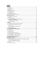
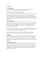
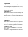
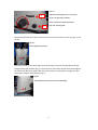
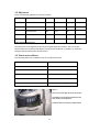
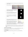
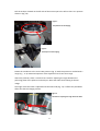
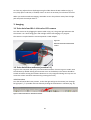
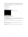
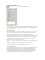
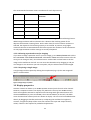
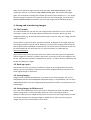
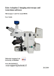
MIU User Guide For Zeiss AxioVert
200 Inverted Fluorescence
Microscope
Molecular Imaging Unit (MIU)
University of Helsinki
www.miu.helsinki.fi
2.9.2009
1
CONTENTS
1. General................................................................................................................. 3
1.1 Instrument .................................................................................................................. 3
1.2 Reservations................................................................................................................ 3
1.3 Billing .......................................................................................................................... 3
1.4 Unauthorized use ........................................................................................................ 3
1.5 Users’ mailing list ........................................................................................................ 4
1.6 User guide ................................................................................................................... 4
1.7 Acknowledging MIU .................................................................................................... 4
1.8 Image processing and analysis ..................................................................................... 4
2. Microscope use ................................................................................................... 4
2.1 Settings for the light path ............................................................................................ 4
2.2 Objectives ................................................................................................................... 6
2.3 Fluorescence filters ..................................................................................................... 6
2.4 Transmitted (bright-field) light microscopy .................................................................. 7
2.4.1 Koehler illumination ............................................................................................. 7
2.4.2 Phase-contrast imaging ........................................................................................ 8
2.4.3 DIC imaging .......................................................................................................... 8
3. Imaging .............................................................................................................. 10
3.1 Zeiss AxioCam HRc 14-bit color CCD camera .............................................................. 10
3.2 Zeiss AxioVision software (version 3.1) ...................................................................... 10
3.2.1 Live view ............................................................................................................ 10
3.2.2 Adjustment of Camera Settings .......................................................................... 11
3.3 Display properties ..................................................................................................... 13
3.3.1 Adding a scale bar .............................................................................................. 14
4. Saving and transferring images ....................................................................... 15
4.1 File formats ............................................................................................................... 15
4.2 Back-up copies .......................................................................................................... 15
4.3 Saving images............................................................................................................ 15
4.4 Saving images in Mcbserver1..................................................................................... 15
4.5 Saving images into your own computer ..................................................................... 16
4.6 Saving images into network folder............................................................................. 16
4.7 Saving images into a USB stick or CD ......................................................................... 16
4.8 Saving images locally ................................................................................................. 16
5. Ending your imaging session ........................................................................... 18
6. Troubleshooting ................................................................................................ 18
6.1 Microscope (both fluorescence and transmitted light imaging) ................................. 18
6.1.1 Fluorescence light microscopy............................................................................ 18
6.1.2 Transmitted light microscopy ............................................................................. 19
6.2 Camera ..................................................................................................................... 19
6.4 AxioVision software................................................................................................... 20
2
1. General
1.1 Instrument
This user guide covers the use of the Zeiss AxioVert 200 inverted epifluorescence
microscope. For more information on each MIU instrument, visit:
http://www.miu.helsinki.fi/instruments/index.htm
An inverted microscope is usually used for observing living cells on culture dishes and bottles
that do not physically fit under an upright microscope. In an inverted microscope, the
condenser is above the specimen plane and the transmitted light source (halogen bulb) is
above the condenser. In an inverted epifluorescence microscope, there is also a light source
(usually a mercury bulb) for reflected light that enables detection of fluorescence signal from
the specimen.
1.2 Reservations
Instructions for Scheduler online reservation system can be found on the MIU web page:
http://www.miu.helsinki.fi/reservations.htm. You can make your reservations two weeks in
advance. The minimum time block you can reserve is 15 min. If you need to cancel your
reservation, it must be done before your reservation starts. Unused and uncancelled
reservations will also be charged.
If you want to extend your session and there are no reservations after you, you can use the
"extend" option in Scheduler (click first on your reservation). If your reserved time is already
up, you cannot extend your present reservation any more.
Make sure you are familiar with the use of Scheduler and MIU user policy and fees
(http://www.miu.helsinki.fi/userinfo.htm and http://www.miu.helsinki.fi/fees.htm).
1.3 Billing
The billing is based ONLY on the reservations made in Scheduler - the logbook markings do
not count. The fee for the one hour training session is 21 € for internal users (July 2008).
Check the current rate on the MIU Fees web page. Any time after the initial training, you can
ask MIU staff to give you additional customized training (charged the same way as the initial
training).
1.4 Unauthorized use
MIU periodically checks the logins of the computers. If your logon/off times exceed your
reserved time in Scheduler, MIU will consider that as unauthorized use of the instrument
and will ask for an explanation. For unauthorized use of the instrument, MIU may issue a
warning. After three warnings, MIU may revoke the user's license. Also, misuse/neglect of
the instrument may lead either to a warning or cancellation of the user license, and the
repair costs may be charged.
3
1.5 Users’ mailing list
All registered users are automatically added to the users’ mailing list. Please read those emails to know what is going on!
1.6 User guide
This user guide will be continuously updated by the MIU personnel. Check that you have the
latest version of the user guide: go to http://www.miu.helsinki.fi/instruments/ and compare
the date of the latest update with the date on the first page of your printed user guide. This
is the only place for update announcements; no e-mails about updates will be sent.
The user guide can also be accessed in the computer through the Internet Explorer browser:
http://www.miu.helsinki.fi/instruments/.
1.7 Acknowledging MIU
Whenever you are using instruments and/or services maintained/provided by MIU, you are
expected to acknowledge MIU in your publications and inform MIU about the papers.
1.8 Image processing and analysis
MIU has two Imaging Workstations that have software for further image processing and
analysis, such as deconvolution, cell counting, and more. Visit the MIU web site or contact
MIU for more information. Use of Imaging Workstations is free of charge, and MIU staff
gives training and help with the software.
In case the commercial and free software do not satisfy your image analysis needs, MIU
provides customized image analysis tools.
2. Microscope use
Put the cell culture bottle or plate on the microscope stage above the objective. If it does
not physically fit there, move the condenser up using the knob shown in Fig. 6.
If you are viewing cells or tissues on an objective slide, place it upside down on the objective
slide holder, and attach the holder onto the microscope stage by pushing it into the holder
frame. Turn the two adjustment wheels connected to the stage on the right-hand side so
that the part you want to view is over the objective.
2.1 Settings for the light path
Turn on the microscope using the green switch on the right side of the microscope. Adjust
the knob on the left side of the microscope between VIS for the oculars and FP for the
camera (Fig. 1, arrow 1).
Rotate the wheel so that a circle is displayed to direct the path of light to the oculars and
front-mounted AxioCam camera (Fig. 1, arrow 2).
4
Figure 1
Adjustment of the light path to a correct port
2
Arrow 1: ocular/camera selection
Arrow 2: selection of the front/side port.
Red circle: focusing knobs
1
Keep the knob below the oculars turned so that the white line points to the eye (Fig. 2, red
arrow).
Figure 2
Ocular light path adjustment
The lower button on the lower right of the microscope is used to activate/deactivate the
halogen (HAL) light pathway (Fig. 3). The control for the amount of light from the halogen is
on the front of the microscope under the camera mount. The fluorescence light path will
open/close using the upper button (Fig. 3).
Figure 3
On/off buttons for fluorescence and transmitted light.
5
2.2 Objectives
There are following objectives in the microscope:
Position
Type
Magn.
NA
Oil/Dry
Phase
1
Plan-Neofluar
10x
0.3
Dry
Ph1
2
LD Achroplan
20x
0.4
Dry
Ph2
3
Plan-Neofluar
40x
0.75
Dry
-
4
LD Achroplan
40x
0.6 korr
Dry
Ph2
5
LD Achroplan
63x
0.75 korr
Dry
Ph3
Table 1. AxioVert 200 objectives
The objectives are changed by manually turning the objective revolver. You can see the
chosen objective in the little LCD display on top of the condenser. In addition, it shows the
halogen lamp and fluorescent shutter status.
2.3 Fluorescence filters
The following filters are available in the microscope filter turret:
Turret position:
Filter:
1
DAPI
2
FITC
3
YFP
4
Texas Red
5
No filter (transmitted light)
Table 2. AxioVert filters.
Figure 4
Filter turret on the right side of the microscope
The white line on the knurled wheel shows the
filter position on the light path
Select the filter by manually turning the wheel
6
2.4 Transmitted (bright-field) light microscopy
Transmitted light microscopy is used for specimens that are stained, or have natural pigment
so they are able to absorb light. Koehler illumination ensures that illumination is
homogeneous and devoid of disturbing scattered light. Thus, adjustment of Koehler
illumination is essential every time transmitted light microscopy is done. Switching
objectives requires readjustments
For transmitted light imaging, make sure that the halogen light pathway is open and that
there is no fluorescence filter in the light pathway (select position 6 in the filter wheel that
has no filter).
Bright-field imaging is usually used for histologically stained specimen but sometimes
unstained specimen can also be observed. All objectives are suitable for brightfield imaging.
For the 10x and 20x objectives, the condenser should be in the position DIC .3-.4. For the 40x
and 63x objectives, select DIC.5-1.4.
Change the condenser position by manually turning the black ring in the condenser (Fig. 5).
You can see the selected condenser position in the window in the front of the condenser
(Fig. 5, red circle).
2.4.1 Koehler illumination
Koehler illumination is needed for achieving optimal illumination. Proceed as follows:
Figure 5
The position of the condenser
Figure 6
Adjusters for field diaphragm (1)
Condenser elevation (2)
Condenser centering (3)
7
-
Select a 10x objective and DIC .3-.4 condenser position by rotating manually the
condenser wheel
-
Focus on the specimen
-
Close luminous field diaphragm until its edges can
be seen through oculars (Fig. 6, a wheel in front of
the top part of the condenser).
-
Focus the image of diaphragm edges by moving
the condenser up or down (Fig. 6, arrow 2).
-
Use centering screws to move the diaphragm
image to the center of the field of view (Fig. 6,
arrows 3).
-
Open the luminous field diaphragm until its edges
are outside the field of view (Fig. 6, arrow 1).
-
Remove one ocular by pulling it out and close the
aperture diaphragm until it is about 80% of the
diameter of the objective pupil. The aperture
diaphragm is adjusted by moving left/right the black level above the condenser
position window in the front of the condenser.
When adjusting Koehler illumination for other objectives, it is sufficient just to adjust
the luminous field diaphragm and the aperture diaphragm without taking out the
ocular.
2.4.2 Phase-contrast imaging
Check that is objective is suitable for phase-contrast imaging. Rotate the condenser so that
the matching condenser position (Ph1 or Ph2) is shown in the front (Fig. 5).
2.4.3 DIC imaging
Turn the polarizer into to the light path (Fig. 9). The polarizer is a round filter above the
condenser.
8
Pull the analyzer located on the left side of the microscope to the left so that it is in position
shown in (Fig. 10).
Figure 7
The polarizer for DIC imaging
Figure 8
The analyzer for DIC imaging
Rotate the condenser to the correct DIC position (Fig. 5). Each DIC position is marked with a
range (e.g. ..3-.4). Numerical aperture of the objective must fit into that range.
Above the polarizer, there is a slider that is used for adjusting the angle between the
polarizing plane of the polarizer and analyzer. Move the slider while looking at the DIC
image.
The angle of the DIC-slider is adjusted with the little knob (Fig. 11). It affects the pseudo3Deffect that the DIC imaging creates.
Figure 9
The knob for adjusting the angle of the DIC-slider
9
As a last step, adjust the iris diaphragm using the slider above the DIC condenser (Fig. 5).
First, fully open it and then, if needed, close it as much as necessary for enhanced contrast.
When you are done with DIC imaging, remember to turn the polarizer away from the light
path and push the analyzer back in.
3. Imaging
3.1 Zeiss AxioCam HRc 14-bit color CCD camera
Turn the camera on by plugging the power cable in (Fig. 12). The green light indicates that
the camera is on. Alternating green and red light means that imaging is in progress.
The camera is coupled with the microscope with a 0.63x adapter.
Figure 10
Back side of the Zeiss AxioCam HRc
camera
3.2 Zeiss AxioVision software (version 3.1)
Log on to the computer with your personal HYAD-username. Choose ‘Log on to ATKK’. Start
the software by double-clicking the AxioVision-icon on the desktop. The camera should be
turned on before starting the software because it is only recognized during start-up. You can
access the online manual for AxioVision by pressing the F1 key.
3.2.1 Live view
Turn the left VIS/FP dial to FP position, so that the light will go to the camera (see "Settings
for light path", p. 3). Enable real-time video by clicking the LIVE-button in software (Fig. 11).
Figure 11 LIVE-mode button in AxioVision software
10
Focusing is done by using the focusing knobs on either side of the microscope. The refresh
rate of live image can be adjusted (Fig. 14). Quality of live image depends on the refresh
rate. However, this setting has no influence on the actual image that will be taken. There are
three options for the refresh rate:
slow (good quality)
medium (medium quality)
fast (poor quality)
Figure 12.
Refresh rate settings for live image
3.2.2 Adjustment of Camera Settings
3.2.2.1 Time of Exposure
Usually CAMERA/ADJUST window is displayed when you start the AxioVision software. If you
do not see a window as shown in Fig. 13, click CAMERA and select ADJUST. There are three
ways to adjust the time of exposure:
the time of exposure can be set manually, either with a slider or by entering the numeric
value
by pressing Measurement, the software automatically estimates the suitable time of
exposure for the current image
by choosing Automatic, the software will automatically estimate the time of exposure for
every snapshot
11
Figure 13
Camera settings in AxioVision software
In the image window there is a "French flag" button in the tool bar at the bottom (Fig. 12).
This will show under/overexposed areas in blue/red pseudocolor. Pressing the button again
removes the pseudocolor.
3.2.2.2 White balance
White balance adjustment is not needed in fluorescence imaging because there is only one
color at a time. However, inappropriate white balance settings may lead to poor image
quality. It is recommended to choose 3200K for fluorescence imaging (Fig. 13).
Correct white balance settings are essential when taking images with transmitted light. The
color of halogen lamp depends on voltage. The color turns from red to blue when voltage is
increased. Human eye compensates for the color variation but the camera should be
adjusted properly. There are three options (Fig. 13):
Interactive... = you have to click on a spot in live image that will then represent white color
3200K = white balance will be adjusted according to color temperature 3200K
Automatic = software estimates suitable white balance for the image
3.2.2.3 Image resolution
There is a list of available camera resolutions for acquisition in BASIC ADJUSTMENT (Fig. 13).
Note that there are three options available for color images: BINNED, STANDARD and
SCANNED. BINNED and STANDARD are faster to take but SCANNED offers better image
quality. When using BINNED resolutions, pixels close to each other are combined. This
results in higher sensitivity (and shorter exposure times) but lower resolution.
12
The recommended minimum camera resolutions for each objective are:
Objective
NA
Recommended min.
resolution
10x
0.3
3900 x 3090
20x
0.4
2600 x 2060
40x
0.75
2600 x 2060
40x
0.6
1300 x 1030
63x
0.75
1300 x 1030
If you are using unnecessarily high camera resolution, the image file size will be high but no
added image resolution will be achieved. This is because the resolving power of the
objective will become a limiting factor. On the other hand, if too low camera resolution is
selected, the objective's full resolving capacity is not utilized. In practice, using higher
resolution than the recommended one will often improve the resolution as the calculations
are only approximations and the settings are usually suboptimal.
3.2.2.4 Selecting a particular area for imaging
If you want to image a particular area in your live image, go to CAMERA/FRAME and tick the
box USE FRAME. Click REFRESH OVERVIEW. Click SELECT FRAME and select some size for the
area (you can change it later). The selected area is outlined with a white frame in the live
image in the small box on the left. You can move the selected area by dragging it, and you
can change its size. Next time you take a snapshot, only the selected area will be imaged.
3.2.2.5 Acquiring a single image
A single image can be acquired by clicking the snap-button (Fig. 14). The new image will
open in a new window.
Figure 14 Single image acquisition
3.3 Display properties
AxioCam-camera can detect up to 16384 separate intensity levels for each color channel.
However, computer monitors can display only 256 levels. The way how 16384 intensity
levels are mapped to 256 can be adjusted. Click the image with right mouse button and
choose PROPERTIES (or press ALT+ENTER). Then choose DISPLAY (on the left). The black
curve describes how intensity levels are shown on display. The curve can be modified either
directly by dragging its handles with mouse, or adjusting the scrollbars for brightness,
contrast, and gamma (shape of the curve that connects the input and output intensity
values). There are also options for predefined adjustments:
13
BestFit shows the whole range excluding specified percentage of actual minimum and actual
maximum values
Min/Max shows the whole range from actual minimum to actual maximum (use for
automatic adjustment of best contrast and brightness)
Linear shows linearly the whole range without detecting actual minimum and maximum
values (use for restoring the original values)
Figure 15 Display tab
With SAVE and RESTORE buttons it is possible to apply the same setting to other images.
3.3.1 Adding a scale bar
Check that you have the correct objective chosen as the scaling is dependent on that. It can
be chosen from the bottom toolbar of the Live window or from the Scalings page. Go to
ANNOTATION/SCALE BAR in the main menu (Fig. 18). Drag a scale bar in the image. Go to
ANNOTATION/SELECT to end the scale bar mode. If you want to change the settings for the
scale bar (color etc.), click with the right mouse button, select PROPERTIES, then on the
menu bar 7 ATTRIBUTES (Fig. 17), and select SCALE BAR.
Figure 16 Adding a scale bar to image
14
When you click with the right mouse button and select VIEW ANNOTATIONS, you will
remove the scale bar. If you select VIEW ANNOTATIONS again, the scale bar will appear
again. The annotations including the scale bar are stored in the meta data on a “.zvi” image.
On other image file formats if you want the scale bar in the saved image, you must select
BURN-IN ANNOTATIONS option before you save your image (see the following chapter).
4. Saving and transferring images
4.1 File formats
It is recommended that you will save your images either in ZVI format. If you use TIFF, only
the image is saved, not the image acquisition parameters. However, almost any other
imaging software (e.g. Photoshop) will be able to open a TIFF file. Also, your image data will
remain unaltered.
The ZVI format is specific for Zeiss AxioVision software. In addition to the image itself, also
the imaging parameters will be stored. However, only some other imaging software will be
able to open ZVI files. SlideBook can open ZVI files, as well as the free AxioVision LE that can
be downloaded from the Zeiss web site. For more information, see MIU web site
(www.miu.helsinki.fi).
The AxioCam camera uses 14 bits per each color channel (red, blue, green) for digitization,
and the images are saved as 3 x 16 bit in ZVI format. If you want to save your images in TIFF
format, they will be converted to 24 bpp (bits per pixel) = 3 x 8 bit so that e.g. Photoshop will
be able to handle your images.
4.2 Back-up copies
Please make sure that you always have back-up copies of your imaging data! One useful
option is to save your images in TIFF format for further image processing, and archive the
same original images in ZVI format.
4.3 Saving images
Images can be saved with FILE/SAVE AS. If you want to save several images, you can use
FILE/EXPORT and then select SEQUENCE (displayed images). In FILE/SAVE AS, you can select
in OPTIONS whether you want to apply display adjustments and burn-in annotations to your
saved images.
4.4 Saving images in Mcbserver1
This is the recommended way for all users that are affiliated with either the MCB or GSB
research programme: create a new folder with your name in the Images-folder in
Mcbserver1 and save your images directly there. You can access the Images-folder from the
microscope computers by selecting Images on Mcbserver (I), when you are saving your
images and you have to select where to save them.
15
You can save images temporarily to that folder and later move them into your own
computer. The folder will be emptied occasionally (it may happen every week for files older
than two weeks).
From your own computer, you can access the Images-folder in several ways:
Appletalk-network: Biomedicum cancerbio / Mcbserver1 / Images
Windows-network: Cancerbio / Snap Server 4400 (Mcbserver1) / Images
FTP: ftp://mcbserver1.hi.helsinki.fi/images/
4.5 Saving images into your own computer
You can also save your images directly to your computer through the network. Only SMBprotocol is supported (works with Windows and Mac OS X). Mac OS X computers are added
to “My Network Places” in Windows as follows:
MacOS X:
- enable: System preferences / Sharing / Services / Windows sharing
Windows:
- choose: My Network Places / Add a network place / Next / Next
- if F-Secure firewall complains something, choose: Allow
- enter two backslashes + your Mac’s IP-address + one backslash + folder’s name, eg.
\\128.214.???.???\folder
- enter some name for the network place
4.6 Saving images into network folder
Drive R: is your personal network folder (in My Computer, has your user name). However, its
capacity is only 100 MB. You can access the same folder also from other Windows
computers on the campus when logging on with your HYAD-username. "My Documents" is a
link to the same folder.
4.7 Saving images into a USB stick or CD
In case of server/network problems, you can use the following options for transferring your
images:
- You can save your images on a USB memory stick. There is an extension cable for
the USB port at the table.
- You can burn your images on a CD. Move images to drive Q: and choose "Write
these files to CD".
4.8 Saving images locally
Drive H: is your personal local folder. Actually it is a link to the automatically created folder
D:\"your username". You can keep your images here at your own risk (no backups are
16
taken!). There is a 3 GB limit for each user. It is recommended to transfer images
somewhere else after your imaging session.
17
5. Ending your imaging session
When you have finished your imaging session you should:
-
Close the fluorescence light shutter (Fig. 3)
Log off from the computer
On working days (Mo-Fr) leave the equipment on if your reservation ends before 16:00. If
your reservation begins before 16:00 and ends after 16:00 and you are not present at 16:00,
please leave AxioVision software on to show that you will continue your imaging session.
If your session ends after 16:00 on a working day, or you are using AxioVert on Saturday,
Sunday, or a holiday, you should turn off the equipment unless somebody has a reservation
after you. You can check that by opening Internet Explorer. The default page of IE shows that
day's reservations for AxioVert.
When turning off the equipment, the following tasks should be carried out:
-
Turn off the fluorescence light
Turn off the microscope
Disconnect the power cable from the camera (Fig. 12)
Write down the time and "off" in the paper calendar
Place the hood over the optics (not over the lamps as they can be hot)
6. Troubleshooting
6.1 Microscope (both fluorescence and transmitted light imaging)
Cannot focus on the specimen:
Working distance of the objective is not enough - use long distance (LD) objective
6.1.1 Fluorescence light microscopy
You cannot see anything:
Is the fluorescence light on? Is the shutter for fluorescence light open (chapter 2.1, Fig. 3)?
Are you using the correct fluorescence filter (chapter 2.3, Table 2)?
Fluorescence lamp doesn’t ignite:
The bulb might be burnt, ask MIU to install a new one.
Fluorescence lamp is on but no light comes to the specimen:
Check that the shutter is open (chapter 2.1).
Fluorescence light image is very noisy:
Check white balance settings (chapter 3.2.2).
18
The whole image is too bright:
Is the transmitted light (halogen bulb) off (p. 5)?
Cannot see the whole field of view:
Is the fluorescence filter correctly in place? Is the shutter for fluorescence light completely
out of the light path (p. 5)?
6.1.2 Transmitted light microscopy
You cannot see anything:
Is the halogen light on (p. 5)? Is the intensity of the light adjusted properly (p. 5)?
The image is too bright and colored:
Check that the shutter for fluorescence light is closed (Fig. 3, p. 5).
Cannot see the whole field of view:
Check that the filters above the condenser are not partially on the light path. Is the
fluorescence light shutter completely closed?
Transmitted light image is too red / too blue:
Is DAPI filter selected? Is the fluorescence light shutter closed? Illumination is uneven =>
adjust Koehler illumination (p. 7). Check white balance settings (chapter 3.2.2).
Phase contrast image is not good:
Are you using a phase contrast objective (Table 1, p. 6)? Does the condenser position match
the objective (pages 6 and 8)? Is your specimen thin enough for phase contrast imaging?
DIC image is not good:
Are you using an objective suitable for DIC imaging (p. 4)? Does the condenser position
match the objective (p. 6 and 8)? Is the DIC slider in position and correctly adjusted (Fig. 9, p.
9)? Is your specimen in a suitable container for DIC viewing (no plastic)?
6.2 Camera
It’s not possible to acquire an image:
Check that the camera is on (chapter 3.1). If the camera was turned on after starting the
software you should exit and restart the software.
Camera image is not in the focus as the image viewed through the oculars:
Adjust the oculars according to your vision (Fig. 2, p. 5).
19
6.3 Computer
It’s not possible to log on to the computer:
Use HYAD user name. Check that the domain selected is ATKK.
I do not have HYAD-username:
You can get it from the user account office. The telephone number is (09) 191 25629 and the
email is [email protected].
6.4 AxioVision software
Any problem:
- Help-command in AxioVision software (F1 or right side of the upper bar) is a useful tool
to get detailed information about AxioVision functions.
20