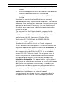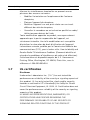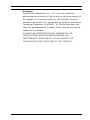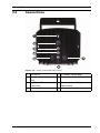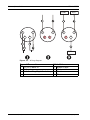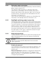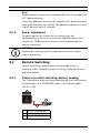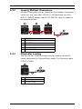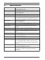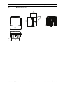
1
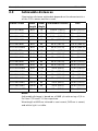
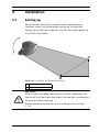
AEGIS UFLED
UFLED
en
Installation Manual
AEGIS UFLED
Table of Contents | en
3
Table of Contents
1
Safety
4
1.1
Safety precautions
4
1.2
Important safety instructions
4
1.3
Important notices
5
1.4
Notifications
7
1.5
Certifications
8
1.6
FCC & ICES compliance
1.7
UL certification
10
8
1.8
Bosch notices
12
2
Overview
13
2.1
Features
13
2.2
Lens / Beam pattern matching
13
2.3
Achievable distances
14
3
Installation
15
3.1
Setting up
15
3.2
Connections
17
3.2.1
Telemetry input connection
19
3.2.2
Day/Night switching output connection
19
3.2.3
Photocell Sensitivity
19
3.2.4
Power adjustment
20
3.3
Remote Switching
20
3.3.1
Camera (or other switching device) Leading
20
3.3.2
Looping Multiple Illuminators
21
3.3.3
Illuminator Leading
21
4
Specifications
22
4.1
Dimensions
23
Bosch Security Systems
Installation Manual
F.01U.123.987 | 1.0 | 2010.04
4
en | Safety
AEGIS UFLED
1
Safety
1.1
Safety precautions
DANGER!
High risk: This symbol indicates an imminently hazardous
situation such as “Dangerous Voltage” inside the product.
If not avoided, this will result in an electrical shock, serious
bodily injury, or death.
WARNING!
Medium risk: Indicates a potentially hazardous situation.
If not avoided, this could result in minor or moderate bodily
injury.
CAUTION!
Low risk: Indicates a potentially hazardous situation.
If not avoided, this could result in property damage or risk of
damage to the unit.
1.2
Important safety instructions
Read, follow, and retain for future reference all of the following
safety instructions. Heed all warnings on the unit and in the
operating instructions before operating the unit.
1.
Cleaning - Generally, using a dry cloth for cleaning is
sufficient but a moist, fluff-free cloth or leather shammy
may also be used. Do not use liquid cleaners or aerosol
cleaners.
2.
Heat Sources - Do not install the unit near any heat
sources such as radiators, heaters, stoves, or other
equipment (including amplifiers) that produce heat.
3.
Liquids - Never spill liquid of any kind, other than water, on
the unit.
4.
Lightning - Take precautions to protect the unit from
power and lightning surges.
F.01U.123.987 | 1.0 | 2010.04
Installation Manual
Bosch Security Systems
AEGIS UFLED
Safety | en
5.
5
Controls adjustment - Adjust only those controls specified
in the operating instructions. Improper adjustment of
other controls may cause damage to the unit.
6.
Power sources - Operate the unit only from the type of
power source indicated on the label.
7.
Servicing - Unless qualified, do not attempt to service this
unit yourself. Refer all servicing to qualified service
personnel.
8.
Replacement parts - Use only replacement parts specified
by the manufacturer.
9.
Installation - Install in accordance with the manufacturer's
instructions and in accordance with applicable local codes.
10. Attachments, changes or modifications - Only use
attachments/accessories specified by the manufacturer.
Any change or modification of the equipment, not
expressly approved by Bosch, could void the warranty or,
in the case of an authorization agreement, authority to
operate the equipment.
1.3
Important notices
WARNING!
When the lamp is running it is hot to the touch. Before touching
switch off the illuminator and allow to cool for a minimum
period of 10 minutes.
WARNING!
LED Radiation
Do not view directly with optical instruments (magnifiers).
Do not stare directly into the lamp at a distance of less than
1.7 m (5.6 ft).
Grounding - For mounting the unit in potentially damp
environments, ensure to ground the system using the ground
connection of the power supply connector (see section:
Connecting external power supply).
Bosch Security Systems
Installation Manual
F.01U.123.987 | 1.0 | 2010.04
6
en | Safety
AEGIS UFLED
U.S.A. models only - Section 810 of the National Electrical Code,
ANSI/NFPA No.70, provides information regarding proper
grounding of the mount and supporting structure, grounding of
the coax to a discharge unit, size of grounding conductors,
location of discharge unit, connection to grounding electrodes,
and requirements for the grounding electrode.
Disposal - Your Bosch product was developed and
manufactured with high-quality material and components that
can be recycled and reused. This symbol means that electronic
and electrical appliances, which have reached the end of their
working life, must be collected and disposed of separately
from household waste material. Separate collecting systems
are usually in place for disused electronic and electrical
products. Please dispose of these units at an environmentally
compatible recycling facility, per European Directive 2002/96/
EC
Environmental statement - Bosch has a strong commitment
towards the environment. This unit has been designed to
respect the environment as much as possible.
CAUTION!
Class I LED Product
Invisible LED radiation when open (850 nm and 940 nm
models). Avoid exposure to beam.
F.01U.123.987 | 1.0 | 2010.04
Installation Manual
Bosch Security Systems
AEGIS UFLED
1.4
Safety | en
7
Notifications
NOTICE! Class 3R notification for 850 nm models
The product is tested and compliant to IEC/EN 60825-1 (2001)
under normal operating conditions, and is classified as a Class
3R LED product. The measured output under the thermal
hazard test (Class 1/3R) was 36.9 mW, peak at 850 nm
wavelength.
The following notification label is placed on the side of the
product:
NOTICE! Class 1M notification for 940nm models
The product is tested and compliant to IEC/EN 60825-1 (2001)
under normal operating conditions, and is classified as a Class
1M LED product. The measured output under the thermal
hazard test (Class 1M) was 22.7mW, peak at 940nm
wavelength. No notification label is placed on the product.
Bosch Security Systems
Installation Manual
F.01U.123.987 | 1.0 | 2010.04
8
en | Safety
1.5
AEGIS UFLED
Certifications
This product complies with European Directive 89/336/EEC and
73/23/EEC Low Voltage Directive meeting the following
standards:
Safety Electrical Safety:
IEC/EN60598-2-5
C22.2 No. 250.0-08
UL 1598
EMC
IP
UL 2108
Eye Safety:
IEC/EN60825-1
Radiated and Conducted EN55022:1998
Emissions
Immunity
FCC
ICES-003 Issue 4:2004
EN50130-4:1995
CFR 47:2007 Part 15.107 &
Ingress Protection
15.109 CLASS B LIMIT
P67 in accordance with BS
EN60529:1992
1.6
FCC & ICES compliance
FCC & ICES Information
(U.S.A. and Canadian Models Only)
This equipment has been tested and found to comply with the
limits for a Class B digital device, pursuant to part 15 of the
FCC Rules. These limits are designed to provide reasonable
protection against harmful interference in a residential
installation. This equipment generates, uses, and can radiate
radio frequency energy and, if not installed and used in
accordance with the instructions, may cause harmful
interference to radio communications. However, there is no
guarantee that interference will not occur in a particular
installation. If this equipment does cause harmful interference
to radio or television reception, which can be determined by
turning the equipment off and on, the user is encouraged to try
to correct the interference by one or more of the following
measures:
–
reorient or relocate the receiving antenna;
F.01U.123.987 | 1.0 | 2010.04
Installation Manual
Bosch Security Systems
AEGIS UFLED
Safety | en
–
9
increase the separation between the equipment and
receiver;
–
connect the equipment into an outlet on a circuit different
from that to which the receiver is connected;
–
consult the dealer or an experienced radio/TV technician
for help.
Intentional or unintentional modifications, not expressly
approved by the party responsible for compliance, shall not be
made. Any such modifications could void the user's authority to
operate the equipment. If necessary, the user should consult
the dealer or an experienced radio/television technician for
corrective action.
The user may find the following booklet, prepared by the
Federal Communications Commission, helpful: How to Identify
and Resolve Radio-TV Interference Problems. This booklet is
available from the U.S. Government Printing Office,
Washington, DC 20402, Stock No. 004-000-00345-4.
Informations FCC et ICES
(modèles utilisés aux États-Unis et au Canada uniquement)
Suite à différents tests, cet appareil s'est révélé conforme aux
exigences imposées aux appareils numériques de classe B, en
vertu de la section 15 du règlement de la Commission fédérale
des communications des États-Unis (FCC), et en vertu de la
norme ICES-003 d'Industrie Canada. Ces exigences visent à
fournir une protection raisonnable contre les interférences
nuisibles lorsque l'appareil est utilisé dans le cadre d'une
installation résidentielle. Cet appareil génère, utilise et émet
de l'énergie de radiofréquences et peut, en cas d'installation ou
d'utilisation non conforme aux instructions, engendrer des
interférences nuisibles au niveau des radiocommunications.
Toutefois, rien ne garantit l'absence d'interférences dans une
installation particulière. Il est possible de déterminer la
production d'interférences en mettant l'appareil
successivement hors et sous tension, tout en contrôlant la
réception radio ou télévision. L'utilisateur peut parvenir à
Bosch Security Systems
Installation Manual
F.01U.123.987 | 1.0 | 2010.04
10
en | Safety
AEGIS UFLED
éliminer les interférences éventuelles en prenant une ou
plusieurs des mesures suivantes:
–
Modifier l'orientation ou l'emplacement de l'antenne
–
Éloigner l'appareil du récepteur;
–
Brancher l'appareil sur une prise située sur un circuit
–
Consulter le revendeur ou un technicien qualifié en radio/
réceptrice;
différent de celui du récepteur;
télévision pour obtenir de l'aide.
Toute modification apportée au produit, non expressément
approuvée par la partie responsable de l'appareil, est
strictement interdite. Une telle modification est susceptible
d'entraîner la révocation du droit d'utilisation de l'appareil.
La brochure suivante, publiée par la Commission fédérale des
communications (FCC), peut s'avérer utile : How to Identify and
Resolve Radio-TV Interference Problems (Comment identifier et
résoudre les problèmes d’interférences de radio et de télévision).
Cette brochure est disponible auprès du U.S. Government
Printing Office, Washington, DC 20402, États-Unis, sous la
référence n° 004-000-00345-4.
1.7
UL certification
Disclaimer
Underwriter Laboratories Inc. (“UL”) has not tested the
performance or reliability of the security or signaling aspects of
this product. UL has only tested fire, shock and/or casualty
hazards as outlined in UP's Standard(s) for Safety for Closed
Circuit Television Equipment, UL 2044. UL Certification does not
cover the performance or reliability of the security or signaling
aspects of this product.
UL MAKES NO REPRESENTATIONS, WARRANTIES, OR
CERTIFICATIONS WHATSOEVER REGARDING THE
PERFORMANCE OR RELIABILITY OF ANY SECURITY OR
SIGNALING RELATED FUNCTIONS OF THIS PRODUCT.
F.01U.123.987 | 1.0 | 2010.04
Installation Manual
Bosch Security Systems
AEGIS UFLED
Safety | en
11
Disclaimer
Underwriter Laboratories Inc. (“UL”) has not tested the
performance or reliability of the security or signaling aspects of
this product. UL has only tested fire, shock and/or casualty
hazards as outlined in UP's Standard(s) for Safety for Information
Technology Equipment, UL 60950-1. UL Certification does not
cover the performance or reliability of the security or signaling
aspects of this product.
UL MAKES NO REPRESENTATIONS, WARRANTIES, OR
CERTIFICATIONS WHATSOEVER REGARDING THE
PERFORMANCE OR RELIABILITY OF ANY SECURITY OR
SIGNALING-RELATED FUNCTIONS OF THIS PRODUCT.
Bosch Security Systems
Installation Manual
F.01U.123.987 | 1.0 | 2010.04
12
en | Safety
1.8
AEGIS UFLED
Bosch notices
Copyright
This manual is the intellectual property of Bosch Security
Systems and is protected by copyright. All rights reserved.
Trademarks
All hardware and software product names used in this
document are likely to be registered trademarks and must be
treated accordingly.
Note:
This manual has been compiled with great care and the
information it contains has been thoroughly verified. The text
was complete and correct at the time of printing. The ongoing
development of the products may mean that the content of the
user guide can change without notice. Bosch Security Systems
accepts no liability for damage resulting directly or indirectly
from faults, incompleteness or discrepancies between the user
guide and the product described.
More information
For more information please contact the nearest Bosch Security
Systems location or visit www.boschsecurity.com
F.01U.123.987 | 1.0 | 2010.04
Installation Manual
Bosch Security Systems
AEGIS UFLED
Overview | en
2
Overview
2.1
Features
13
The AEGIS UFLED range of infrared and white light illuminators
for CCTV, features patent-pending illumination technology and
installation friendly design.
–
Patent pending Constant Light technology automatically
compensates for LED degradation to deliver a constant
level of lighting performance for the life of the illuminator
–
3D Diffuser technology enables increased surveillance
range, wider beam patterns and evenly illuminated nighttime images
–
Energy efficient, low voltage operation means quick and
easy installation
–
High efficiency surface mount LEDs deliver improved
thermal management, long life and low cost of ownership
–
Semi-covert, covert and visible white light versions
available
–
Easy integration with day/night cameras with relay
contacts COM/NC/NO that indicate whether the photocell
has activated the illuminator
–
Telemetry input connection allows illuminator to be
switched via a voltage free relay contact from a day/night
camera signal, remote signal or PIR.
–
Pressure equalisation valve prevents thermal expansion
and pressure cycling problems within the illuminator head.
2.2
Lens / Beam pattern matching
The illuminator should be matched to the scene and the camera
lens focal length. Before installation ensure that the illuminator
has been correctly specified to support the CCTV system. When
planning a system take into account the achievable distances,
the lens/beam pattern and filters.
Bosch Security Systems
Installation Manual
F.01U.123.987 | 1.0 | 2010.04
14
en | Overview
2.3
AEGIS UFLED
Achievable distances
Illumination distance achievable depend on the characteristics
of the CCD camera and lens used.
Product Code
Wave-
Beam
Achievable Distance
HOV
length
Angle
UFLED10-8BD
850
10
220 m (720 ft)
40 m (125 ft)
UFLED20-8BD
850
20
150 m (490 ft)
55 m (175 ft)
UFLED30-8BD
850
30
110 m (360 ft)
60 m (195 ft)
UFLED60-8BD
850
60
70 m (230 ft)
80 m (265 ft)
UFLED95-8BD
850
95
50 m (165 ft)
110 m (360 ft)
UFLED120-8BD
850
120
35 m (115 ft)
120 m (400 ft)
SLED10-9BD
940
10
135 m (440 ft)
25 m (80 ft)
UFLED20-9BD
940
20
80 m (260 ft)
28 m (100 ft)
UFLED30-9BD
940
30
65 m (210 ft)
35 m (115 ft)
UFLED60-9BD
940
60
40 m (130 ft)
45 m (145 ft)
UFLED95-9BD
940
95
30 m (100 ft)
65 m (210 ft)
UFLED120-9BD
940
120
20 m (65 ft)
70 m (230 ft)
UFLED10-WBD
White
10
60 m (195 ft)
10 m (30 ft)
UFLED20-WBD
White
20
40 m (130 ft)
15 m (50 ft)
UFLED30-WBD
White
30
35 m (115 ft)
20 m (65 ft)
UFLED60-WBD
White
60
25 m (80 ft)
30 m (100 ft)
UFLED95-WBD
White
95
20 m (65 ft)
45 m (150 ft)
UFLED120-WBD
White
120
15 m (50 ft)
50 m (165 ft)
Notes:
Achievable distance is based on a 20dB s/n ratio using a 1/2-in.
Ex-View CCD and F1.4 lens aperture.
Wavelength at 850 nm infrared is semi-covert, 940 nm is covert,
and white light is visible.
F.01U.123.987 | 1.0 | 2010.04
Installation Manual
Bosch Security Systems
AEGIS UFLED
Installation | en
3
Installation
3.1
Setting up
15
Set up the unit correctly to obtain the best performance.
Optimum results are achieved by setting up at night and
viewing the results on a monitor. Use the illustration below to
assist with installation.
Figure 3.1
Installing an AEGIS UFLED lamp
1
Nearest point
2
Furthest object
CAUTION!
When the unit has been operating for a while it becomes hot.
Switch off the illuminator and allow it to cool for a minimum of
10 minutes before touching.
Do not look directly into the unit at a distance of less than
1.7 m.
Bosch Security Systems
Installation Manual
F.01U.123.987 | 1.0 | 2010.04
16
en | Installation
1.
AEGIS UFLED
Attach the illuminator to a pan and tilt unit, wall bracket or
camera housing as required.
2.
Connect the illuminator to a 12–24 VDC or to a 24 VAC
(±15%, 50/60 Hz) power supply.
3.
Commission the mains supply, camera, and monitoring
control equipment.
4.
Adjust the pan of the illuminator to match the camera’s
field of view.
5.
Loosen the bolts on each side of the unit and adjust the
vertical alignment to maximize the results; re-tighten the
bolts.
6.
Tilt the unit downwards until the near part of required field
of view is saturated with light as viewed on the monitor.
7.
Slowly tilt the unit upwards until the furthest part of the
required field of view is illuminated correctly on the
monitor.
F.01U.123.987 | 1.0 | 2010.04
Installation Manual
Bosch Security Systems
AEGIS UFLED
3.2
Installation | en
17
Connections
Figure 3.2
AEGIS Illuminator Rear Panel
1
2
Photocell
Pressure Equalization
5
6
IR Power Adjustment
Power Input 12 VDC/24 VAC
3
Vent
Day/Night Camera
7
Photocell Sensitivity
4
Switching
Telemetry Input
Bosch Security Systems
Installation Manual
Adjustment
F.01U.123.987 | 1.0 | 2010.04
18
en | Installation
AEGIS UFLED
2
1
4
2
1
4
3
3
COM
N/O
1
2
4
3
N/C
Figure 3.3
Wiring diagram
Type of Connection
1 AC/DC Power In
2 Telemetry
3 Volt Free Day/Night Switching
F.01U.123.987 | 1.0 | 2010.04
Installation Manual
Cable Color
4 Brown cable
5 White cable
6 Black
7 Blue
Bosch Security Systems
AEGIS UFLED
3.2.1
Installation | en
19
Telemetry input connection
The illuminator can be activated remotely by a remote switching
device, camera signal or PIR.
The telemetry input connection is a Normally Open (NO)
contact that is switched by a volt-free contact across pins 1
(brown) and 3 (blue) of the connector cable. For this function
to work correctly, the photocell must be disabled so that the
illuminator is continuously On.
Check that the switching device contacts are closed when the
illuminator is Off and open when the illuminator is On.
3.2.2
Day/Night switching output connection
The day/night output can be used to switch a day/night camera
to its monochrome night mode if the illuminator is switched On.
To use this function, it is necessary to determine if the camera
requires an NO or an NC circuit to switch into its night mode.
Use the telemetry cables to link the brown and blue wires to
the camera switching input if a NO circuit is required to activate
the night mode. If a NC signal is required to activate the night
mode, use the brown and black wires.
3.2.3
Photocell Sensitivity
To adjust photocell sensitivity first remove the sealing cap, then
adjust the potentiometer to turn the lamp on at the desired
lighting conditions.
NOTICE!
Replace the sealing cap after adjustment to ensure water
ingress protection.
Disabling the photocell
Turn the photocell fully clockwise to disable the photocell. The
lamp will remain on all the time unless the telemetry input is
closed circuit.
Photocell OperationThe photocell is designed to automatically
switch the lamps ON at dusk and turn OFF at dawn. A high
degree of hysteresis is incorporated to avoid ON/OFF switching
in marginal light conditions.
Bosch Security Systems
Installation Manual
F.01U.123.987 | 1.0 | 2010.04
20
en | Installation
AEGIS UFLED
Note:
Potentiometer Factory set at mid-point 500 Lux ON and 850 Lux
OFF (approximately).
Check the photocell functions by covering with black tape and
having the telemetry link closed. The photocell operation has an
in-built delay of up to 5 seconds.
3.2.4
Power adjustment
To adjust power, first unscrew the sealing cap; the
potentiometer is set at the maximum calibration point (fully
clockwise). To decrease the power, turn the potentiometer
counter clockwise.
NOTICE!
Replace the sealing cap after adjustment to ensure water
ingress protection.
3.3
Remote Switching
Various switching configurations can be made using an
interface cable. Commonly used switching configurations are
explained below.
3.3.1
Camera (or other switching device) Leading
The illuminator may be activated remotely by a volt-free contact
latched across the TELEMETRY input. Use interface cable
UFLED-CI-5M.
1
2
3
UFLED Illuminator
Camera
UFLED-CI-5M
F.01U.123.987 | 1.0 | 2010.04
Installation Manual
Bosch Security Systems
AEGIS UFLED
3.3.2
Installation | en
21
Looping Multiple Illuminators
Multiple illuminators can be linked for synchronous illuminator
switching. Use link cable (UFLED-CL-1M) between the DAY/
NIGHT CAMERA output and the TELEMETRY input as shown in
the diagram below.
1
2
3
4
5
6
3.3.3
UFLED Illuminator 1
UFLED Illuminator 2
UFLED Illuminator 3
Camera
UFLED-CI-5M
UFLED-CI-1M
Illuminator Leading
The DAY/NIGHT CAMERA output may be used to switch the
camera between the Day and Night mode. Use interface cable
(UFLED-CI-5M).
1
2
3
UFLED Illuminator
Camera
UFLED-CI-5M
Bosch Security Systems
Installation Manual
F.01U.123.987 | 1.0 | 2010.04
22
en | Specifications
4
AEGIS UFLED
Specifications
LEDs
High efficiency Surface Mount LEDs with current
Beam patterns
Wavelength
limited integral circuits
10°, 20°, 30°, 60°, 95°, 120°
850 nm, 940 nm and visible white light
Average life
Power Consumption
(model dependent)
> 10 years
26–45 W (45 W max power)
Power consumption will vary over time due to
optical output control which compensates for LED
Input voltage
degradation and ambient temperature fluctuations
12–24 VDC or 24 VAC
Temp range
Ingress Protection
Construction
(±15 %, 50/60 Hz)
-40°C to +50°C (-40°F to 122°F) max on full power
in accordance with BS EN60529:1992
Robust aluminium extrusion with acrylic front
Dimensions
Color
Weight
Power cable
Bracket
Accessories
–
Power Supply
window
152 x 130 x 115 mm (6.0 x 5.1 x 4.5 in.)
IR: Black anodized heat sink with black front fascia
White Light: Black anodized heat sink with clear
fascia
1.4 Kg (3.1 lbs)
Supplied with IP67 power connector and 5 m (16.4
ft) of connecting lead
Wall mount U bracket included
Bosch PSU-224-DC100
Other compatible power supplies may be used,
ensure the above voltage and power requirements
–
Telemetry Cable
are met.
Bosch UFLED-CI-1M
–
Link Cable
Universal 5 m cable for telemetry.
Bosch UFLED-CI-1M
Dedicated 1 m cable to synchronize multiple
illuminators
F.01U.123.987 | 1.0 | 2010.04
Installation Manual
Bosch Security Systems
AEGIS UFLED
4.1
Specifications | en
23
Dimensions
130.0
(5.12)
89.5
(3.52)
152.0
(5.98)
mm
(in.)
Bosch Security Systems
Installation Manual
F.01U.123.987 | 1.0 | 2010.04
24
en | Specifications
F.01U.123.987 | 1.0 | 2010.04
AEGIS UFLED
Installation Manual
Bosch Security Systems
Bosch Security Systems, Inc.
www.boschsecurity.com
© Bosch Security Systems, Inc., 2010