1
Dear Owner,
Welcome aboard your new 11 :METRE One Design.
manual helpful and informative.
We hope you will find this
Your decision to own a 11 :METRE One Design is a source of great
to us. and we are confident your new boat will provide the same
for you.
By selecting an 11 :METRE Olle Design. you have
confidence in us. and you can be certain that we have made. and
every effort to support your trust.
satisfaction
satisfaction
expressed
will make.
(
Every 11 :METRE is manufactured of the rillest materials available by
dedicated professionals and craftsmen. It asks only that you treat it as Olle of
the family, and it will return all you can ask of it and more. This manual is
intended to guide you through your first few days of ownership, as weIl as to
provide information on care and maintenance that should be of value over
the lire of the yacht.
t
Before getting underway, please take the time to familiarize yourself with
the operations and functions of the various systems designed into your
11 :METRE to ensure proper operation.
In the event that additional
information is needed, we suggest you consult your dealer.
Please accept our congratulations. Have fun and smooth sailing!
Sincerely
yours,
International
One Design Group
TABLE OF CONTENTS
c-
e
(
lntroduction
Section
Intent of Manual
Format of Manual
Warranty
Owner
Responsibility
Commissioning
Introduction
Recommended Tool and Equipment List
Keel Installation
Rudder Installation
Fitting the Spars
Preparation
Halyard Installation
Spreader Installations
S landing Rigging Installation
Raising the Mast
Tuning lhe Rig
1.1
1.2
1.3
1.4
Section 2
2.1
2.1.1
2.2
2.3
2.4
2.4.1
2.4.1.1
2.4.1.2
2.4.1.3
2.4.1.4
2.4.1.5
t;
)
.1
Installing the Boom
Rigging the Running Rigging
Prelaunch Checks
Hull Inspection
Before Mast is Stepped
Equipment on Board
Postlaunch Checks
Interior
Inspection
Electrical
Inspection
Rigging and Sails
Launch Procedure
Rig Tuning Underway
Weather Helm
Rig Maintenance
Rigging and Lines
Owner
Responsibilities
(
S~stems
2.5.2
2.5.3
2.6
2.6.1
2.6.2
2.6.3
2.7
2.8
2.8.1
2.9
2.9.1
Section 4
-Ogtional
4.1
4.2
4.2.122.12.212
4.2.
4.2.
4.2.
4.3
4.3.
4.3.
4.4
4.5
4.6
4.7
4.8
4.9
Section 5
Maintenance
Introduction
Gelcoat Surfaces
Stainless Steel
Below the Waterline
Bottom Cleaning
Bottom Preparation
Bottom Painting
Hardware
Haul Out Procedure
After Hauling -Extended
2.5.1
3.1
3.2
3.3
3.3.1
3.3.2
3.3.3
3.3.4
Introduction
Electrical
General Description
Battery
Discharged State
Clean Connections
Galley
General Description
Water System
Lifeline and Pulpits
Trailer
Cradle
Motor Mount
Outboard Motor
Portable Toilet
General
2.5
Section 3
Introduction
Mandatory Equipment
Recommended Equipment
Medical Kit
Tool Kit
Spare Parts
Dealer Responsibilities
Yacht
2.4.1.6
2.4.1.7
5
5.2.3
5
Storage
5.4.4..4..4.
5 1
5 2
5 3
5 .5
5.6.6.
5 1
INTRODUCTION
1.1
INTENT
SECTION 1
OF MANUAL
This manual is intended to acquaint you with the various features of
your yacht and to provide information related to the care and upkeep of
the yacht and its equipment.
The manual does not necessarily cover
equipment which you may add to the vessel.
Manuals applicable to
these items should be consulted tor operation.
1.2
FORMAT
OF MANUAL
The manual is divided into five basic sections:
(
Section 1, this section, contains abrief
description of the contents and
format of the manual, and the warranty.
The warranty information
included on the following page should be read carefully.
Section 2 of the manual covers the procedures that should be followed
when commissioning the yacht. This section of the manual should also
prove useful in subsequent recommissionings after periods of layup.
Section 3 highlights the suggested owner responsibilities.
any way represent a training document.
It does not in
Section 4 addresses options which may apply to your baal.
Section 5 is a suggested maintenance schedule.
1.3
)
WARRANTY
Your 11 :METRE Olle Design has been careful1y inspected and tested prior
to shipment from the factory.
Because of this attention to quality
control, Dur warranty is Olle of the most effective in the industry.
Your
warranty is included at the rear of this section. Be sure to follow the
instructions on fitting out and forwarding.
Your can rest assured that
Dur policy towards your warranty will result in your satisfaction.
W ARRANTY
RESPONSIBILITY
OF THE OWNER
Your prompt return of the warranty registration will help us ensure
continued satisfaction.
Your dealer will provide you with the required
information
and will
cosign
the warranty.
Please return
the
manufacturer's copy within thirty (30) darg after taking delivery of
your new boat.
Your dealer will competently handle any service problems that may
arise.
It is essential that you contact hirn für all warranty matters.
When it is necessary to contact us. please address your letters as foliows.
indicating your boat and hull number:
Precision Boat Works
1511 18 Avenue Drive East
Palmetto, FL 34221
2.
5.
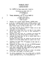
WARRANTY
POLICY
11:METREONE D~IGN
The 11:METRE One Design warranty policy is backed by:
International One Design Group AB
Osterlanggatan 14
S-lll 31 Stockholm
Sweden
Warranty administration in the U.S. will be handled by:
Precision Boat Works
1511 18th Avenue Drive East
Palmetto. FL 34221
(813) 722-6601
(
3.
Warranties will
4
In the case of equipment installed on the 11:METRE supplied by other
manufacturers,
the individual
manufacturer
warranty shall apply.
This includes, hut is not limited 10, such items as spars, standing
rigging, running rigging, and deck hardware items.
be reported through authorized 11 :METRE dealers.
All warranty repair items must be preapproved.
forfeit fights to full reimbursement.
Failure to do so may
International One Design Group, AB, is not liable for travel expenses
and lost time incurred by the dealer (or dealer representative) to
perform warranty work.
6.
International Olle Design Group, AB, in conjunction with Precision Boat
Works, may elect to have the boat returned to the dealer or factory.
7
International One Design Group, AB, does not warranty finishes, such as
gel coat, varnishes, and paint.
International One Design Group, AB, warranties the basic hull and deck
structure to be free from structural defectS for aperiod of one (1) year.
9.
International One Design Group, AB, warranties all
period of one (1) year.
other items für a
10.
International One Design Group. AB. does not warranty
installed by the dealer. owner. or other third party.
11.
In the case of vessel alteration, abuse, improper care and maintenance
and/or neglect, International Olle Design Group, AB, may choose, at its
discretion, not to warranty certain items.
12.
International One Design Group, AB, shall not be liable to the purchaser
for any injury, vessel damage, or logs however caused.
13.
The effective commencement date of this warranty policy is coincident
with the commissioning date.
The warranty registration form must be
returned within thirty (30) days of the commissioning date.
equipment
,
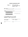
WARRANTY
Return to:
HIN #: PCW 33
Dealer:
REGISTRATION
FORM
Precision Boat Works
1511 18th Avenue Drive East
Palmetto, FL 34221
Date:
Owner:
I, the undersigned, have read and under
International Olle Design Group, as it applies
acknowledge and accept the conditions of thi~
Dealer's Signature
Owner'g
Date
Date
Signature
COMMISSIONING
2.1
SECTION 2
INTRODUCTION
The first commissioning of a yacht is essentially the start of the yacht's
lire. and the importance of proper commissioning procedures at this
time cannot be overestimated.
The commissioning procedure will be
performed by authorized personnel and while no owner participation is
required. it is highly recommended.
Complete lists of the pre-Iaunch and post-launch checks employed
during commissioning are provided in this section für those owners
interested in understanding the commissioning procedure, as weIl as
für future use in any recommissionings that may be required after
periods of wet or dry storage. The lists assume performance by persons
cognizant of the procedures that are required and do not attempt to
provide step-by-step instructions.
c
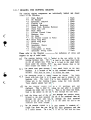
The factory installed equipment and items of owner responsibility that
require attention during commissioning are included in the list.
These
items are marked with an asterisk (*).
2.1.1 RECOMMENDED
TOOL AND EQUIPMENT
I,Q.Q.l.s.
Screwdrivers Assorted Phillips
Pliers -Slip Joint
Pliers -Needle Nose
Pliers -Linesman
Ballpeen Hammer
Socket Wrench Set
Machinists File
Rigging Knife
Razor (Utility) Knife
Caulking Gun
Hex Wrenches -Assorted
Hex Wrench -5/8"
(
.
EQuigment
Rigging Tape
Sandpaper
Hardwood Block
Silicone ODe Tube
Rags
Solvent
S~ares
Miscellaneous Nuts
Bolts
Cotter Pins in Various Sizes
and Standard
LIST
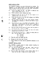
KEEL
INSTALLATION
Tbe 11:METRE is shipped to your dealet~ with
installation is a very simple procedure. Tbe
1,600 Ibs. (725 kg) and the hull (w ithout
1,800 lbs. (820 kg). Tbe basic procedure is as
(
a)
Position and support the keel ()In the trailer or cradle. The keel
must be braced laterally and for 'e and aft.
b)
Remove protective sleeves from
c)
Suspend the boat over the kee] with
predrilled holes in the hüll botl
d)
Slowly tower the boat to test fit the keel w i t h 0 u t
compound. Tighten the nuts.
e)
Mark any areas on the keel thai need further grinding. Normallyhe
this should not be necessary as t
keels are test fitted to a jig at
the factory.
f)
Make sure that the keel is perpeI
easily done by measuring alon
datum point.
Then measure fi
datum points on the keel.
g)
Once all is fitted, wipe the areas with solvent, sand the gelcoat on
born hull and keel. Solvent wiI Je again.
h)
Cover both the hull recess and keel top and sides with beddingM
compound such as Sika Flex or 3
i)
:Ithe
ldicular
el.
;s
le
keel bolts.
5/8" -70
ft.-1bs.
1/2" -38
ft.-Ibs.
botts
aligned
any
to
thetom.
bedding
5200.
Install the backup plates anddasfolIows:
j)
Clean the excess and smooth the joint.
k)
Retorque the keel botts after 48 hours.
)
the
to the waterline. This isg
the hull. P&S, to establish a~om
this point to equally placed
Lower the boat fully onto the kel
nuts. The nutS should be torquel
.)
(
the keel not insta11ed. Tbe
FRP encassed keel weights
rig) weighs approximately
foliows.
Please reference the class rufes tor permissible alterations to the
keel.
RUDDER,
INSTALLATION
The 11 :METRE is supplied without
rudder is a very simple operation.
tbc rudder installed.
Installing
the
a)
First check the rudder for fairne~
Design rufes for permissible a
fairing is best done at this time.
b)
Slip the rudder stock through tl
tower hearing, taking care to
insure that the shaft is aligned with the upper hearing.
and finish.
Refer to the OneIterations
to the rudder.
Final
(
:k
L
ssembled
ssengers
c)
Continue to insert the rudder through the top hearing. At this
point the rudder stock is throug:h the cockpit sole.
d)
Slip the thrust washer over the sitock and let it rest on the upper
bearing holder flange.
e)
Slide the split bronze rudder stoc head all the war down until it
meets the washer. Align the rudder to centerline. The split in
the rudder stock head should be pointed forward and aligned
with the boat centerline.
f)
Tighten the bolt which squeezes the fitting.
g)
Tighten
h)
Place the tiller head over the stock head fitting.
tighten the holt and nut.
i)
Lower the tiller until it rests on the vertical adjustment screw in
the top of the stock head fitting
j)
If the tiller angle needs changing. simply adjust the screw.
the
set
screws
which
further
rotating on the stock.
prevent the
fitting
Insert
and
CAUTION: NEVER USE ANY TYPE CF CIJ OR GREASETO LUBRICATE THE
RUDDER BEARINGS.
2.4
FITTIN G THE
SPARS
2.4.1 PREPARATION
All of the spar components should be a
in a clean. dry area.
The mast should be blocked up from tbe ground and supported at the
ends and olle intermediate point. The IJnainsail track should be up. The
standing rigging should be segregated by type (i.e., upper shrouds,
intermediate shrouds, etc.).
2.4.1.1 HALYARD
INSTALLATION
a)
The mast is provided with me:
for the halyards. These
are light lines used to pull the halyards through the mast.
b)
The general procedure is to untie the upper end of one
messenger, securly tape it tlJ the appropriate haIyard. and
slowly pull the messenger until the haIyard exilS the spar. This
is best accomplished with two people -one to feed the haIyard
and one to pull the messenger.
c)
Tbe halyards are labeled and s,hould include:
Main Halyard
Jib H alyard
Spinn~ I.ker
Halyard
Pole I ..ift
d)
The maiß haIyard is rove over the ill
sheave in the mast head.
.'
e)
Tbe spinnaker halyard is lead over lhe forward
sheave in lhe
mast head.
f)
The jib halyard is ted over the sheave in the forward face of the
spar. immediately below the attachment point of the forestay.
g
The pole
lift
is rove over the sheave. midway
on the
forward side.
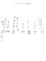
2.4.1.2 SPREADER INSTALLATION
a)
Knot the halyard tails on the maiß. jib and spinnaker halyards.
Knot the pole lift tail.
b
Pull the halyards and pole lift shackles down and secure them to
the upper spinnaker pole ring.
(
t
c)
Tension the halyards by knotting them at the rope exit. Coil the
halyards and securly tie off to the tower portion of the mast.
d)
Preassemble the spreader bar to Olle spreader.
both the upper and lower spreader assemblies.
e)
Insert the spreader bars through the slots as shown.
The
spreaders angle art and up. Insure that the haIyards lie on the
aft side of both the upper and tower spreader bars.
f)
Slide the opposing spreader over the bar and insert the
lnstall the lock nuts. File any sharp burrs.
.g )
The jumpers
lnstall the fabricated jumper strut assembly.
angle forward. Use the fasteners and pretapped holes. Use
'Never Seize' or similar on the fasteners.
2.4.1.3 STANDING
a)
<-
This applies to
RIGGING
INSTALLATION
All of the side shrouds utilize 'T' terminals at the upper end. To
assemble hold the terminal at 90 degrees to the backing plate.
Insert the head of the terminal, turn 90 degrees and pull down.
See Diagram.
b)
c
Instali
d)
Lead the shrouds over the spreader tips. The upper shroud should
be ted over the forward slot of born upper and tower spreaders.
The intermediate shroud should be ted over the aft slot of the
tower spreader.
e)
the upper and intermediate shrouds in this manner.
le
:HE
n
f)
Replicate the same operations in a) on the running backstays
and check stars. Remove and replace the stainless cover plate
for installation.
g)
Install the headstay at the hound fitting by inserting the clevis
piß through the fork fitting.
Insen the cotter piß. spread the
piß 5 degrees and silicone the tip.
h)
Instali
the backstay eye in the mast head crane via a similar
procedure.
i)
Lead the backstay between the running backstays,
j)
Instali the jumper wires.
Use [j
'T' Terminal technique on the
upper end. Lead the wire thra ugh the jumper strut tip.
The
tower end is secured to the tane fitting located above the upper
spreader slot.
k)
t- »
1
Pull all standing rigging taut and tape or tie off at lower end of
the mast.
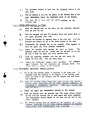
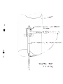
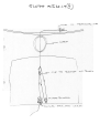
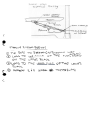
2.4.1.4 RAISING THE MAST
The mast can be instalied with the boat either on land or in water.
Raising the mast is best accomplished with three people.
The usual
assortment of tools is needed. However, no specialty tools are required.
Additionally,
you will use the spinnaker pole, spinnaker sheet.
spinnaker turning blocks and a winch handle.
WHEN RAISING OR LOWERING 1
ARE CLEAR OF ELECTRICAL
WIE
RESUL T IN SERIOTJS HARM OR D1
(
MAST. INSURE THA T YOUtES.
FAlLURE Ta DO SO MA Y::A.IJI.
a
First, place the mast on the I:loat, hut do not secure in thesome
tabernacle.
You will need
padding and blocking tocoat.
prevent damage to the deck gel
b
Uncoil the jib halyard tail and lead it through the lower turning
block on the starboard side of the mast tabernacle. Then lead
the tail to the starboard outboard sheet stopper.
c
Shackle the spinnaker turning block to the starboard aft
mooring loop eyelet. Shackle the ratchet spinnaker turning
block to the starboard eyestrap at the forward end of the
handrail.
Shackle the other spinnaker turning block to the
forward port mooring loop.
d)
Lead the spinnaker sheet throu!! the three blocks, through the
handrail tube. stopper and ratc tlet block, then to the starboardlcwise
turns are required around
cabin top winch.
Three cloc
tailer
foot and through the self
the winch. then over the self
tailer jaws.
Ised
Dn
vertical.
rnd
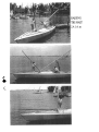
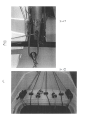
e
Rig the spinnaker sheet to the clc
loop on the underside of the
See Photo.
outboard spinnaker pole fitting.
f)
Shackle the jib halyard to the sI~innaker sheet shackle as shown.
See Photo.
g)
Rig the main backstay.
Tbe backstay wire is shackled to the:al
starboard pad eye on the vertic
face of the transom opening.:
Pass it through tbe block on the end of the backstay wire to the
tackle system.
h)
Locate one of the tabernacle pivot pins.
i)
Remove the intermediate shrouds and headstay from their secure
position on the mast.
j)
Pinle
Fully extend the turnbuckles on the intermediate shrouds.
the turnbuckle clevis pins to t1 aft chainplate hole. Note that
the cotter pin should be on the inside of the chainplate.
k)
Move the mast back into positil
and align the upper sleevedlacle
hole.
A large screwdriver)nally,
mast hole with the upper taben
helps in chis operation. Additi{
oDe person will need to
hold the spar up to avoid dama!~e to the deck. Alternatively set
up a tall sawhorse.
1)
Insert
the tabernacle
pin
water soluble lubricant
and piI L it.
arior tc
Lubricate
~ins
with
non-I
insertion.
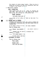
m)
Tension
Attach the spinnaker pole to the tower spinnaker ring.
the jib haiyard until the pole is perpendicular to the mast.
Lock off the spinnaker sheet
Tension the spinnaker sheet.
stopper. One person will need to hold the spinnaker pole from>to
swinging sideways. See the ph(
illustrating the set up.
n)
Start to grind the winch to raise: the mast. The aft person can
walk forward holding the mast to ease the load.
The forward
person should only be concenIled with keeping the spinnaker
pole in line and making gure that the intermediate shroud
turnbuckle toggles are in line ~rith the chainplate. See Photo.
0)
The mast is temporarily
Keep raising the mast until it is
stahle. DO NOT RELEASE TB E SPINNAKER HAL YARD.
p
Once the mast is raised. insert,
(don't forget to lubricate). .A.illli
q)
Attach the upper
Loosen the ties securing the starlding rigging.
now
disassemble
the spinnaker
and lower shrouds.
You may
pole rig.
r)
Preassemble the backstay tackle system. The upper block is a
non-swi veling block. The I ower block is shackled to the
padeye on the aft port cockpit face. Lead the line forward to
the 2:1 purchase then lead the other line thru the console
blocks to the cam cleats.
piß, the tower
the foresta~.
tabernacle
piß;h
i'
2.4.1.5 TUNING
THE RJG
The rigging needs to be tensioned bei
properly support the mast before goil
following
procedure.
a)
The forestay turnbuckle rigging
mid point position.
b)
The backstay should be lightly
the mast stable.
c)
Adjust the maiD haIyard and tellsion to the point where it can
just be stretched to a common I?oint on the chainplate P&S. The
objective is to align the mast head to the center of the boat.
Adjust the upper shrouds untill, with equal pressure on the
halyard. it stretches to the same point on the chainplates P&S.
d)
Now,
e)
Equally
tension the intermediate shrouds hand tight.
f)
Equally
tension the tower shrouds hand tight.
g)
Sight up the mainsail track to check für straightness.
Adjust
intermediate and lower shrouds until the mast is straight.
h)
If a
Now further tension the upper a.nd tower shrouds equally.
Loos tension meter is available, set the shrouds to the following
tensions.
(
t
sailing.19 The objective is to
We recommend the
sailing.
should be adjusted to the
-only
enough
by counting the turns on 1
turnbuckle, equally adjust the
turnbuckles to tension the upper shrouds. Adjustment should be0
done with open end wrenches. D.! NOT USE ANY MANNER SJ.B
OF THE
DEVICE
TO INCREASE
LE VERAGE -GALLING
IN A SEIZED
THREADS
COULD
OCCUR .RESULTING
TURNBUCKLE.
32
Uppers
Lowers
l
are
5crews
tensioned
:he
Jard
to
i)
Check again for straightness per (g).
j)
Lastly,
tension
the
intermediate
shrouds
35
Olle
turn
past
tight.
k)
The rig is now pretuned.
1)
li ne
Tie
a light
turning
during
2.4.1.6 INSTALLING
the turn buckle
betweentrials.
bodies to
prevent
THE BOOM
a)
Attach the forward end of the boom to the gooseneck fitting
the mast.
b)
Rig the maiß halyard to the outb(
raise it.
on
end of the boom. in order to
.
2.4.1.7 RIGGING
THE
RUNNING
RIGGING
The running rigging components are individually
consist of the following:
a)
b)
c)
d)
e)
f)
g)
h)
i)
j)
k)
1)
m)
n)
("
t
0)
p)
q)
r)
s)
Main Halyard
Jib Halyard
Spinnaker Halyard
Topping Lift
Running Backstays
Shock Cord, Running Backstay
Check Star Line
Main Sheet
Traveler Control Lines
Backstay Line
Jib Sheet
Jib Traveler Control (2 Parts)
Boom Vang Wire
Boom Vang Rope
Foreguy
Spinnaker Sheets
Dock Lines
Cunningham (2 Parts)
Spinnaker Twing Lines
1
1
1
1
2
1
2
1
2
1
1
1
1
1
1
2
2
1
2
Each
Each
Each
Each
Each
Each
Each
Each
Each
Each
Each
Each
Each
Each
Each
Each
Each
Each
Each
for definition of cleats and
Please reier to the Diagram
stoppers on top oi cabin trunk.
a)
labeled and should
to the eye splice in the
The running backstay wire is SJ
running backstay rope.
The rOD is lead to the large fixed blocklere
it is lead to the small bullet
on the aft cockpit face. From tJ
block under the console, throu eh the deck blocks, then to the
sheet stopper and finally
b)
winch.
e very small block on the main
The shock cord goes through tJJ
backstay. It is secured to the )ort and starboard checkstay twist~f()re
shackles.
This
must he done b,
rai~in!? the mast.
c)
The fiddle
The checkstay tackle is rigged Detween its blocks.
upper
end
and
is
pinned
to the,ck
block with jam cleat is at the
is
then
shackled
to
the
fork
backstay wire.
The tower bl(
fitting piß in the running backstay, using the twist shackle.ard.
Twist shackle should face inbo
d)
Rig the traveler control liDes in a 3:1 purchase port and
starboard. This is dolle by k:lotting the end after it is passed~ar.
Then to the fixed end block.
through the rolled tube on the
back to the sheave on the car and then through the cam cleat.
e)
Lead the bitter end of the jib sheet through the traveler block.
forward to the deck mounted block art of the stemhead. then aft
through the port side banal ail. through the deck mounted
block at the aft end, to the b lock on the cabin top and to the
outboard port sheet stopper.
(
lackled
wo
to th~
f)
part system. It consists of a
The jib traveler control is a t
single line from the car, thro ugh the mast grommets and then'line
to the car and lead the bitter
to a tackle system. Tie a bo~
g)
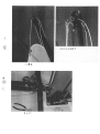
The boom vang is a 2: 1 tack1e J/hich then goes to a 6:1 tackle.
This yie1ds a 12:1 total purchase The wire portion of the boom
vang and the trip1e block with Decket are shack1ed to the vang)t.
The wire is led through the
plate on the aft face of the ma:
wire sheave block on the boOIn and then to the tripie blockDve
(without becket). The line is r
through the blocks and then
art to the starboard swive1 cleat with bullseye. Be careful not to:ffi.
See photo.
cross the lines in the tack1e systc
h
The 2: 1 cunningham tackle is de: ended to the small upper aft
hole in the starboard ear of the mast tabernacle. The '5' hock onlooks
into a grommet or 'D' ring
the standing end of the system
is
ted
aft to the starboard cam
in the mainsail luft.
The line
cleat.
i)
Shackle the fiddle block
The main sheet is a 6: 1 tackle
with becket to the traveler car. Shackle the fachet block to the
swivel base.
Shackle the fida le block without hecket to the
SeelS.
forward boom bail.
The single block is on the art bail.
diagram tor reeving instructioI
j)
The spinnaker pole foreguy is (4 2: 1 system. The line is dead
ended with a bow shackle on the hole in the upper forward
corner of the starboard tabernacJe ear. The line is then passed
through the single block with snap shackle, through the mast,m
cleat located between the two
grommet holes and art to the c.
When rigging the foreguy, theoIe
swivel cams with bullseyes.
bridle ring.
block is shackled to the lower D
k)
The spinnaker sheets are riggeo as outlined in the section on
The exception is that the liDeblocks
raising the mast (Section 2.4.1.
port and starboard. The
is also led through the twing
twing lines are rigge;d by simpl y passing the bitter end through
the midship outboard bullseye aIJathen to the cam cleat.
Ri~gin~
the Hal~ards
(
ld
system.
rom
d)
its mast exil to the upper
The spinnaker halyard is lead I
e
mast
tabernacle then to the
starboard turning block on th
starboard inboard sheet stoppeJ
,
This completes the running rigging in
Please note that the
halyard tails are stowed in the cabin. The companionway hatch boardropes.
is designed to allow clearance for the
2.5 PRELAUNCH CHECKS
HULL
INSPECTION
Check topsides, decks. and all inteJ'ior spaces for cleanliness and
proper finish.
Make cenain that all toreign matter hag been removed
from the bilge areas, and check the fc 11owing specific items:
Rudder operational.
(
* Anti-fouling
bottom paint app
Rudder
keel
and
trailing
edg(
faired
per ciass roies,
if so
desired.
2.5.2
BEFORE MAST IS STEPPED
WARNING: Move ~our boat to a Dositllm that is clear of overhead wires
or obstructions.
Electrocution ma~ result tram contact with a n ~
overhead
wire~.
See the details in Section 2.5.2 for sp:lr and rigging
preparation.
Check the following items:
mast.
Shrouds, stars, spreaders,
in~
*Masthead lights and mast-mo!
operational, if equipped.
*YHF antenna instalied, if equJ
(
8
(.
stallation.
:s
lllted
All chafe points on mast propeJ
EQUIPMENT ON BOARD
Check the following
items:
Winch handles.
* Ground tackle.
*Dock lines and fenders.
and properly
instrument
units
secured to
*Safety equipment:
PFD's (life preservers)
Throwable horseshoe or ring buoy
Horn
Ship's bell
etc.)
Emergency signals (flar<
Fire extinguishers
Other equipment as requ
in your area.
*Medical
kilo
*Spare parts and tool kit.
2.6
(
POSTLAUNCH CHECKS
2.6.1 INTERIOR
INSPECTION
Make an overall inspection of the hu1. interior. Check bilge areas für
evidence of any leaks near keel bolt~ or transducers and then make
the following specific checks:
~
Check through-hull tranduce]
2.6.2 ELECTRICAL
INSPECTION
Make the following checks of the electrical system if equ~pped:
Check the 12-volt supply at the electrical panel.
Make an operational check of all DC circuits connected to the
electrical
2.6.3 RIGGING
panel.
THE SAILS
Check the following
\
All
8
after mast is in pt.
standing rigging
complete and in place, dockside
tuning
completed.
All cotter pins in place and tape
c
:5.
ired
Llnched
Running rigging
in place.
*Sails hoisted to check fit.
2.7
LAUNCH PROCEDURES
The 11 :METRE One Design may be la
marine lift or by a fixed hoist or CJ
minimum capacity of two tons. F1oat la
draft of the boat.
either by a conventional:ane.
The crane must have aLlnching
is impractical due to the
When crane launching, use the followi ng procedure.
a)
Attach the single short bridle hoo~ to the eye on the keel bolt.
Attach the two lang bridle line s to the art port and starboard
mooring loops. The line mus!t be attached to the heavy guage
portion of the fitting.
The aJtt lines are necessary because the,
boat with mast is stern heav)/ with respect to the center pick
up. This situation is accentuat~ed without the mast in place.
b)
Pul! the boom to the side of the boat.
c)
d)
Pull the running backstays forwaI!d to clear the hoist.
e)
Attach bow and stern lines.
Review prelaunch checklist in Section 2.6.
f)
Take liW
g)
tension on the hoist.
h)
Release trailer tie downs.
i)
Double check that all is clear and then lift boat sufficient amount
to clear trailer.
Clear trailer and lower the boat to the water.
j)
The reverse of this procedure should be used on haut out.
2.8
RIG
TUNING
UNDERW A Y
With the jib and maiß set. under Inoderate wind conditions. saiI to
windward on Olle tack. Sight up the Dlast to check for straightness. The
If the need for
mast should not bend to leeward or to windward.
proper
adjustment
to the upper,
adjustment is indicated. make the
observing
the
folIowing
mIes.
lower. and intermediate shrouds while
If a take-up adjustment is indicated, g 0 on the opposite
shroud is more easily adjusted.
tack so that the
Always tack in born directions to engure straightness of the mast.
C'
If at all possible, avoid adjusting the upper shrouds since this will
the mast perpendicularity.
e
(
affect
2.8.1 WEATHER HELM
amount of "weather helm".
The rake of the mast will alIect .the
is
raked
art and decreases as the
Weather helm increases as the mast
s
to
rake
should provide a slight
rake is reduced.
Final adjustment:
[lditions.
weather helm in moderate wind CO!
2.9
RIG
MAINTENANCE
2.9.1 RIGGING
AND LINES
ld toggles with fresh water and. if
Clean wire rope. swage fittings. aI1
lt.
Use a stiff brush or nylon
desired. a water soluble detergen
teel
wool
or cleansers containing
scrubbing pads.
Do not use s
chlorine.
.
(
~.
3.1
(
j.:l
(
c
b)
Prepare yourself for any situatiol1l before going out on the water.d
Follow the instructions providel in the sections of this owner's
manual, and all applicable U.S. Coast Guard and other
regulations.
c)
If
d)
Before leaving the dock, be gure that al1 your equipment is inaware
working order, that you are :
of the weather conditions,:amiliar
and that someone ashore is j
with YOUf destination or
afloat plan.
you are not
an experienced
sailor, you should attend an
accredited sailing school.
COAST GUARD SAFET' Y EQUIPMENT
MANDITORY
with the U.S. Coast Guard
Many safety items are required for cornI
regulations. Note that these regulations are subject to change. It is the
asents
owner's responsibility
to be cogniz aßt of current regulations
for Recreational
Boats."
outlined
in the "federal
Requirem
Additional copies may be obtained b:y writing the Consumer Affairs
20953, or by
Starr. V.S. Coast Guard Headquarters, Washington. DC
caIling (202) 472-2384.
Depending on the length. passenger c.lpacity, and operating conditions.
'ding to the current U.S.C.G.
Jour boat must be equipped aCCOI
regulations.
Be sure that you operate your boat with the necessary
PFD's (life preservers), fire extinguis berg, signaling devices. distress
signals, navigation lights, etc.. as reie rred to in the "Federal Requirements tor Recreational Boats."
RECOMMENDED SAFETY EQUIPMENT
Preparation is the key to safety on the water. As a minimum guide. we
recommend that you outfit your boat ~,ith the following equipmem:
Updated
nautical
of
YO1 intended cruising
flashlight
\\rith spare batteries.
charts
area.
Boat hook.
(
.
Iliance
ur
Large
waterproof
Four fenders.
Bilge pump.
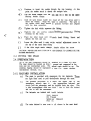
3.3.1 MEDICAL
KIT
Every yacht should carry a first aid manual and a medical kit tailored
Any ship's storekit.
to the specific needs and capabilities of the owner.
should carry a standard type medical
3.3.2 TOOL KIT
A basic kit should consist of:
Wrenches -adjustable,
open en.d, box, socket
Hammers -large
and small
with marlinspike
Screwdrivers -Iarge
and smalI. standard and phillips
regular. cutting and needle nose. vi se grips
cutter -capable
Hacksaw -with
of cutting standing rigging
spare blades
3.3.3 SPARE PARTS
(
A basic kit should consist of:
-Standing
rigging
repair materials
turnbuckles. stainless wire. clevis pins.
~i
such as cotter pins,
Running rigging and sail repair material such as blocks, extra
line, duct tape.
Assortment of stainless steel screws, nuts, bolts, and washers.
Electrical tape. wire. crimp on lugs.
Lubricating supplies -WD-40,
Chafe tape -white
silicone grease.
vinyl.
YACHT SYSTEMS -OPTIONAL
8
(
.Wire
4.1
SECTION
4
INTRODUCTION
Your 11 :METRE One Design may be equipped with certain options.
In
general,
manufacturers
instructions
pertaining
to
specialized
equipment should be reviewed.
4.2
ELECTRICAL
PACKAGE
The electrical
package is designed to power your
running
lights,
if
equipped.
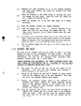
4.2.1 GENERAL DESCRIPTION
A single battery 12-volt DC electrical system has been installed on your
11:METRE One Design. A switch panel supplies the yacht's electrical
loads.
The electrical circuit is shown in the schematic in Figure
.All 11 :METRE One Designs are prewired at the factory.
BATTERY
With proper care, the battery will provide lang and satisfactory
service.
Proper care is not diffict 1ft if a few basic points are
remembered.
4.2.2.1 DISCHARGED STATE
Leaving a battery in a discharged st:
for any length of time can
result in a permanent logs of capacity. Doing so in cold weather can:
destry the battery since it will freeze at relatively low temperatures.
At the end of each season remove youIr battery, charge it, and store itor).
in a warm place (not on a cement flol
Be sure that the battery is
fully charged before reinstalling it in the spring.
~
4.2.2.2 CLEAN CONNECTIONS
{
A cup full of strang baking~an
Keep battery connections clean and tiglJ
soda solution and a toothbrush will cl!
corrosion tram the terminals
and neutralize any spilled acid (do n(>t allow any of the solution tof
eDler the battery cells).
A coating 0 petroleum jelly on the battery
terminals will inhibit corrosion.
"
4.3
GALLEY
The galley is designed as a self contained unit.
It provides
necessary rudimentary cooking facilities für limi ted cruising.
GENERAL
DESCRIPTION
The galley is equipped with a single
self contained gas stove.
Replacement gas can be purchased at most department stores with anurers
outdoor department. Follow manufact
instructions für use and
.
care.
W A TER SYSTEM
c
The water system is manual. Water i~ pumped into the sink from the
jerry can with the hand pump. The sink water is dumped overboard.
The water should be replaced frequent,iy to insure freshness.
4.4
(-
lte
lt.
)burner,
>dons.
:adle.
the
LIFELINE
AND
PULPITS
Lifelines and pulpits are all available °I
refer to Section 5.3.
The lifelines sho
turnbuckle should be pinned and tappe(
4.5
TRAILER
Refer to
4.6
For care of the stainlessuld
be adjusted undl taut. Thei.
trailer
manufacturers instructic:>ns for
care
and
maintenance.
CRADLE
Refreshing the paint and
The cradle is a coated steel folding c]
oiling the moving connections is all tha,t is required.
.
MOTOR MOUNT
See Section 5.3 for maintenance of aluminum.
OUTBOARD MOTOR
An outboard motor is an individual choice. A 4.5 HP motor is perfectly
adequate for most situations.
A 25" shaft is recommended. Refer to
manufacturers
instructions.
PORTABLE TOlLET
Refer to supplied instrUctions.
MAINTENANCE
(
5.1
~
SUMMAR Y
SECTION5
INTRODUCTION
This section of the manual consists 0: a summary of the maintenance
required for the hull. deck and interio
GELCOAT SURFACES
A fresh water hose-down of deck and topsides at every opportunity, plus
an occasional washing with soap anld water will help preserve the
gelcoat surfaces. Use a spange or a :soft brush on the smooth surfaces,
and a stiff brush on the non-skid ar(~as. Rinse thoroughly with fresh
water to avoid streaking.
CAUTION:
Do not use abrasive clt~aners for cleaning.
dull the gelcoat surface.
It will rapidly
At least once a year, the smooth gl~lcoat surfaces should be cleaned
thoroughly,
washed, and polished.
P\.cetone can be used for cleaning
stubborn areas.
Abrasive cleaners sh,ould be used sparingly, if at alt.
Use a wax especially formulated für jjberglass surfaces.
CA U TI 0 N :
Never use acetone on any plastic parts. Avoid using too
much acetone or from puddling the acetone on gelcoated areas that
have come in contact with acetone should be wiped off and rinsed
immediately with fresh water.
(
r.
mmable,
vapors can accumulate in
CA U T ION:
Acetone is highly fla
This can cause a lire
hall
air.I.ys
closed space.
Vapors are heavier t
the
warning labels on
heed
resulting in personal injury.
Alw~
acetone containers.
5.3
STAINLESS
STEEL AND
ALUMINUM
As our environment is changing, it hag become increasingly important
to protect meta! surfaces exposed to the atmosphere. We recommend
cleaning stainless steel and aluminuI n with a metal polish (i.e.. nonParticular
abrasive) and coating with wax thre:e (3) times per year.
attention should be given to welded connections.
BELOW THE WATER LINE
With the exception of small crat't that are removed from the water after
each use, all vessels require same form of bottom protection to avoid the
accumulation of bottom growth,
The class ruIes also require bottom
paint, This usually needs to be done on a yearly basis, Although fresh
water areas do not generate as much fouling as occurs in saft water, it
nevertheless will cause growth of moss, grass, and other flora that will
significantly affect the performance of the yacht,
CA U T ION:
Always wear the appropriate protective equipment when
cleaning,
sanding,
painting,
etc.
Always
heed manufacturers
recommendations, failure to do so may result in injury or illness.
5.4.1 BOTTOM CLEANING
(
Cleaning the accumulated growth from a boat bottom is far easier
when the growth is wet than after it has been allowed to dry out.
While still wet. a power spray and stiff brush will remove most bottom
growth. Barnacles that resist this action can be removed with a
scraper.
BQTTOM
PREPARATION
Most bottom paints require removal of all loose material from the
bottom, and a thorough hut light sanding of any portions of the old
paint that remains in good condition.
A proper sanding procedure will
normally take off approximately the same amount of old paint as it's
intended to be reapplied.
This avoids excessive paint accumulation
that will eventually cause peeling and roughness on the bottom.
5.4.3 BOTTOM
The actual formula of the bottom paint that should be applied iso to a
great extent, determined by the general area in which the yacht is
expected to operate (fresh or galt water, temperate or tropical areas,
etc.).
Local advice from reputable yards is helpful. Application of
bottom
paint
should
always
conform
to the manufacturer's
instructions if maximum effect is to be achieved. Some bottom paints
recommend thinning, others do not.
Some specify that the boat be
returned to the water before the paint hag completely dried out
(usually 3 or 4 darg) and others make no qualifications in this area,
hut may have other requirements.
(
8
,
PAINTING
(
CA U TI 0 N:
Some bottom paint formulas are not compatible with others
and cannot be applied directly over Olle another without proper
preparation. The owner should keep arecord of the type bottom paint
that is in use to avoid any problems in this area.
5.5
HARDWARE
Deck hardware can easily be maintained by thoroughly flushing with
freshwater.
This is true for both fresh and saltwater environments.
Suspended silt in freshwater and satt in seawater will reduce the
performance of hearings, blocks stoppers, etc.
Winches should be
maintained in accordance with the winch manufacturers procedurcs.
Loose deck hardware should always be stored below to prevent UV
degredation and theft.
,
.
HAUL OUT PROCEDURE
Basically reverse the steps in the launch procedure. Thoroughly
and clean the bottom.
wash
If the boat is to be derigged, reverse the steps in all procedures in
Sections 2.4 and 2.5.
AFTER HAULING
.EXTENDED
STOI
Wash topsides, deck, and alt other extlerior fiberglass surfaces.
except the non-skid surfaces.
(
Wax all
Remove all sails; follow sailmaker's instructions in regard to cleaning,
and store in a dry place.
Remove all sheets and lines. clean. and store in a dry place.
If the mast hag been removed from the yacht, remove all stars and
shrouds from the mast.
Wash the entire star or shroud assembly,
using freshwater and a stiff brush, dry thoroughly, and coil into large
non-kinking coils.
Store the coils in a dry place. Wash and wax all
spars, coil halyards into non-kinking coils, and secure them to the
mast. Store the mast outside with adequate support along its length.
If mast is to remain stepped, remove boom, clean. and store as
described before; clean shroud/stay end fittings, toggles, etc. using
freshwater and a stiff brush apply g. light coating of silicone grease.
paying particular attention to the en<1 fittings where they connect to
the stars and shrouds.
Remove
all
electronic
gear that
may require
servicing
during
the
winter.
(
Remove fire
recharging.
extinguishers
für weighing, checking, and any necessary
If security is likely to be a problem. remove easily stolen items such as
compasses and radio transmitters; store in a safe place.
If cushions are left aboard, place on edge to encourage ventilation.
If the boat is to be covered, ensure tJlat the cover is installed in such a,tion,
war as to provide adequate ventil~
and that the cover is not
permitted to chafe against portions 01 the hull.
If the boat is not to be covered, ensure that mechanisms such as
winches are provided with adequate covers.
If the mast is to remain stepped. snub all shrouds and haiyards to
minimize noise and wear.
k~
(
'P l-U~
ll,J"T"'O
ß~(..lL1
P '- /r1r'I,:,:""
~
('
J
- 1, s-'r.1
--
I
M\""'f'\:"1-
IU
,.
(
8
(
1-
!,
_I
1--
-.-
'~
!'-
<:;:;"t':..~~
"'r:c:J\'2-
?~li)c'N
CD ~U\
~
upp~
S~(Z..~I.,::;.~
~
'S ~
'PLrrz::.G:
+ -n."t1"2--U
(3)
TVoJ'- ~\
'=?1).J~
~N../r\.-1-
L .r \, "-J...
r~
WL~~
@
c... L.. l P
'fC.) c::..\::'"'"i\ -i-'- --<"!.
\..JJt~
~ pC2..-et'"rO
\::::.~
~
1
0 ~..;
o~
(,LJQ~~:O~
..T\ ~ L"ri1"L.
"-t
~~~
~~
(..I,::
~ os
-~I Y ) ,-
n?
~I!:'I~~~~
\,).J\.~
Tlt-I.:=;
C) F-i=-
~ ~ (2.C-..roQ
~
,~
~'-I:~
~ tt4.?c:: '\:)~
o~
0 I...-;-:'3 c../tiZ-.:D
I..."'.),~c.;-
--=
~a
"T1.AJl ~ i'\-~
~'CJ
'C
)
o\&'~
.
S \c...c:~~
~~
:<.t+.\,'3@)
~;f'I
u~r::;-
.
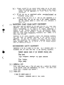
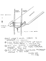
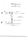
RAISING
THE l\'lAST
2.4.1.4.m
(.
'S'-,c...:::..~~
(
~
\
~
L t- E
CD ne::
C::i)
Q)
~
f2..c.. A.=
L~
--:0-0
DU
n't-t..=:
C-c~
""TC)
\2:.<=.
-e=:. 'l I I.J <;
~ 1S."r'L.
-A..A.
-ra
i3 I~--.!!:-~
u t-,.l.~~
Sola~
~PP'==5"'C..
i\t"\..::-
cu
~
C>\':c'
I Oc..~
-r
r Z
Co)}..:) M_~T
~ (.j~
(ov;-::;".,t(2..~)
A ~\1"1'""f)-\L..::-
'"S L. 0 '- \(,...
vPP\::'C7- ~ l ~ e-
c..~
.,-,-n.;
L.O(..l",l~
~ l-O C-l,-
~
~"
(
'\?.e e\:c:{~
~~~
w 0 ra,A..c-..s-
-r-~
~~~'1d
<../i-.::.L::
..
;.
i
.~~
(
j,
2.-~
M /'rI1-.j :s. fT'\~
'9"7
Sc:=.:::r7.~
.
..Ä..,
'iZ-C'I.,::'
-v l l.,4
(
-
~
St ~
\..1.3
.-~
1=1 a 0 L:...
~
t'a L. C:C... Lc
f
t
~oCJM
0
~~.
~
..,:"t...\.~
~
~
-
';.
"'..~.
e
..':
\ '.
,
.
.
0;:',
,~.
-',,:
..
~
:'0
0;'
\,~, ~..
..
.:~
~.
..'
:: ,'"
° ~:'~i,"!
.,
";k--"
..
.
t
..
~
.,..
\
~.
.,,
!'
.
, CO
0 ;O;~
.'
;.',
.,
--
1 i
." ~ ':'
=.~!!
'"C ",'.~;:;'Q),
,. -.0-
CI)
CC
~.
w
"
CI)
C
CC
.-
C
~'QJ
C "'a:.
C
0.2
C
~
CI)
.
"
..~
..-':~
: =.-Q) .-,
CI).,::.
'Q.
"
=
0')
CI)
Q)
~
0
CI) C
C
O')
"ccCC-'
G>
CCCCC"
A
~CI)CI)Q)
~.5.5Q
~
;!'..;-
.
~
~ ~ ~ ~
0 = .-
=..Co
C -,
CI) 'W
~
~= Q)
~Q) -~
--~...
>O')CO
C
C
~
.w ...
.-0')
;
c "
0,
,.-
~,
~ . ,".
..', .
'. ..
-"
.
' '.'
z
w
w
0
~
J:
U
U)
.".
c
~
...
c
U)
N:'
.~
.O'
W
as-
cf,
Q)
C
~.
>
C>
:(0
~
~
(/)
~
Q)-
w
Z
~
W-
0
U)
~
~
:..I
Co
@
(j).. '
.--