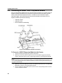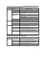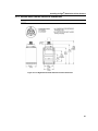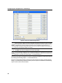
1
Finger GmbH & Co. KG • Schamerloh 84 • D-31606 Warmsen • Internet: www.finger-kg.de • email: [email protected] • Tel. (+49) 57 67 9 60 20 • Fax (+49) 57 67 9 30 04 Finger GmbH & Co. KG • Schamerloh 84 • D-31606 Warmsen • Internet: www.finger-kg.de • email: [email protected] • Tel. (+49) 57 67 9 60 20 • Fax (+49) 57 67 9 30 04 Installing In-Sight® 5000 Series Vision Sensors Copyright, Trademarks, Patents The software described in this document is furnished under license, and may be used or copied only in accordance with the terms of such license and with the inclusion of the copyright notice shown on this page. The software, this document, nor any copies thereof may be provided to or otherwise made available to anyone other than the licensee. Title to and ownership of this software remains with Cognex Corporation or its licensor. Cognex Corporation assumes no responsibility for the use or reliability of its software on equipment that is not supplied by Cognex Corporation. Cognex Corporation makes no warranties, either express or implied, regarding the described software, its merchantability or its fitness for any particular purpose. The information in this document is subject to change without notice and should not be construed as a commitment by Cognex Corporation. Cognex Corporation is not responsible for any errors that may be present in either this document or the associated software. This document may not be copied in whole or in part, nor transferred to any other media or language, without the written permission of Cognex Corporation. Cognex P/N 597-0027-05 Copyright © 2003-2007 Cognex Corporation. All Rights Reserved. The hardware and portions of the software described in this document may be covered by one or more of the following U.S. patents (other U.S. and foreign patents are pending): Hardware 4,972,359; 5,526,050; 5,657,403; 5,793,899 Vision Tools 5,495,537; 5,548,326; 5,583,954; 5,602,937; 5,640,200; 5,717,785; 5,742,037; 5,751,853; 5,768,443; 5,796,868; 5,818,443; 5,825,483; 5,825,913; 5,845,007; 5,859,466; 5,872,870; 5,909,504 The following are registered trademarks of Cognex Corporation: Cognex Cognex, Vision for Industry In-Sight "crosshair" logo In-Sight The following are trademarks of Cognex Corporation: The Cognex logo Other product and company names mentioned herein are the trademarks, or registered trademarks, of their respective owners. i Copyright, Trademarks, Patents ii Installing In-Sight® 5000 Series Vision Sensors Regulations/Conformity Declaration of Conformity Manufacturer: Cognex Corporation One Vision Drive Natick, MA 01760 USA Declares this -marked Machine Vision System Product Product Number: In-Sight 5000: P/N 800-5840-4 In-Sight 5100/5110: P/N 800-5870-1; P/N 800-5870-1R (RoHS Compliant) In-Sight 5100C: P/N 800-5837-4; P/N 800-5837-4R (RoHS Compliant) In-Sight 5400/5410: P/N 800-5855-1; P/N 800-5855-1R (RoHS Compliant) In-Sight 5400S/5410S: P/N 800-5855-3; P/N 800-5855-3R (RoHS Compliant) In-Sight 5400C: P/N 800-5837-4; P/N 800-5837-4R (RoHS Compliant) In-Sight 5400CS: P/N 800-5837-6; P/N 800-5837-6R (RoHS Compliant) In-Sight 5401/5411: P/N 800-5838-4; P/N 800-5838-4R (RoHS Compliant) Complies With: 89/336/EEC Electromagnetic Compatibility Directive Compliance Standards EN 55011:1998 + A1:1999 + A2:2002 Class A EN 61000-3-2:2000 + A2:2005 EN 61000-3-3:1995 + A1:2001 EN 61000-6-2:2001 European Representative: Cognex France Immeuble le Patio 104 avenue Albert 1er 92563 Rueil Malmaison France Safety UL and CUL Certification marks are present on products. LISTED FCC FCC Part 15, Class A This device complies with Part 15 of the FCC Rules. Operation is subject to the following two conditions: (1) This device may not cause harmful interference, and (2) this device must accept any interference received, including interference that may cause undesired operation. This equipment generates, uses, and can radiate radio frequency energy and, if not installed and used in accordance with the instruction manual, may cause harmful interference to radio communications. Operation of this equipment in a residential area is likely to cause harmful interference in which case the user will be required to correct the interference at their own expense. iii Regulations/Conformity Declaration of Conformity Manufacturer: Cognex Corporation One Vision Drive Natick, MA 01760 USA Declares this -marked Machine Vision System Product Product Number: In-Sight 5400R/5410R: P/N 800-5829-1; P/N 800-5829-1R (RoHS Compliant) Complies With: 89/336/EEC Electromagnetic Compatibility Directive Compliance Standards EN 61000-6-4:2001 Class A EN 61000-3-2:2000 + A2:2005 EN 61000-3-3:1995 + A1:2001 EN 61000-6-2:2001 European Representative: Cognex France Immeuble le Patio 104 avenue Albert 1er 92563 Rueil Malmaison France Safety UL and CUL Certification marks are present on products. LISTED FCC FCC Part 15, Class A This device complies with Part 15 of the FCC Rules. Operation is subject to the following two conditions: (1) This device may not cause harmful interference, and (2) this device must accept any interference received, including interference that may cause undesired operation. This equipment generates, uses, and can radiate radio frequency energy and, if not installed and used in accordance with the instruction manual, may cause harmful interference to radio communications. Operation of this equipment in a residential area is likely to cause harmful interference in which case the user will be required to correct the interference at their own expense. iv Installing In-Sight® 5000 Series Vision Sensors Declaration of Conformity Manufacturer: Cognex Corporation One Vision Drive Natick, MA 01760 USA Declares this -marked Machine Vision System Product Product Number: In-Sight 5403/5413: P/N 800-5830-4; P/N 800-5830-4R (RoHS Compliant) In-Sight 5403S: P/N 800-5830-6; P/N 800-5830-6R (RoHS Compliant) Complies With: 89/336/EEC Electromagnetic Compatibility Directive Compliance Standards EN 61000-6-3:2001 + A11:2004 Class B EN 61000-3-2:2000 + A2:2005 EN 61000-3-3:1995 + A1:2001 EN 61000-6-2:2001 European Representative: Cognex France Immeuble le Patio 104 avenue Albert 1er 92563 Rueil Malmaison France Safety UL and CUL Certification marks are present on products. LISTED FCC FCC Part 15, Class B This device complies with Part 15 of the FCC Rules. Operation is subject to the following two conditions: (1) This device may not cause harmful interference, and (2) this device must accept any interference received, including interference that may cause undesired operation. v Regulations/Conformity Declaration of Conformity Manufacturer: Cognex Corporation One Vision Drive Natick, MA 01760 USA Declares this -marked Machine Vision System Product Product Number: In-Sight 5600: P/N 800-5871-1R (RoHS Compliant) In-Sight 5603: P/N 800-5873-1R (RoHS Compliant) Complies With: 89/336/EEC Electromagnetic Compatibility Directive Compliance Standards Class A1 EN 61000-6-4:2001 Class A EN 61000-3-2:2000 + A2:2005 EN 61000-3-3:1995 + A1:2001 +A2:2005 EN 61000-6-2:2005 Compliance Standards Class B2 EN 61000-6-3:2001 +A11:2004 Class B EN 55022:1988 +A1:2000 +A2:2003 Class B EN 61000-3-2:2000 + A2:2005 EN 61000-3-3:1995 + A1:2001 +A2:2005 EN 61000-6-2:2005 European Representative: Cognex France Immeuble le Patio 104 avenue Albert 1er 92563 Rueil Malmaison France Safety UL and CUL Certification marks are present on products. LISTED FCC Class A1 FCC Part 15, Class A This device complies with Part 15 of the FCC Rules. Operation is subject to the following two conditions: (1) This device may not cause harmful interference, and (2) this device must accept any interference received, including interference that may cause undesired operation. This equipment generates, uses, and can radiate radio frequency energy and, if not installed and used in accordance with the instruction manual, may cause harmful interference to radio communications. Operation of this equipment in a residential area is likely to cause harmful interference in which case the user will be required to correct the interference at their own expense. FCC Part 15, Class B This device complies with Part 15 of the FCC Rules. Operation is subject to the following two conditions: (1) This device may not cause harmful interference, and (2) this device must accept any interference received, including interference that may cause undesired operation. 1. Using Cognex Power Supply ACC-24I or equivalent Class A power supply. 2. Using Cognex Power Supply PS-Kit-1 or equivalent Class B power supply. FCC Class B2 vi Installing In-Sight® 5000 Series Vision Sensors Precautions Observe these precautions when installing In-Sight 5000 series vision sensors to reduce the risk of injury or equipment damage: • In-Sight 5000 series vision sensors are intended to be supplied by a Listed, Direct Plug-In Power Unit with a minimum output rated 24VDC, 600mA and marked Class 2, Limited Power Source (LPS). Any other voltage creates a risk of fire or shock and can damage the In-Sight components. • Do not install In-Sight 5000 series vision sensors where they are directly exposed to environmental hazards such as excessive heat, dust, moisture, humidity, impact, vibration, corrosive substances, flammable substances, or static electricity. • To reduce the risk of damage or malfunction due to over-voltage, line noise, electrostatic discharge (ESD), power surges, or other irregularities in the power supply, route all cables and wires away from high-voltage power sources. • The housing of the sensor is internally connected to the system ground wire (pin 8 of the Breakout cable). Therefore, if the mounting surface of the sensor is at a nonzero ground potential, it is strongly recommended that the sensor be mounted on an isolated or non-conductive mount. • Do not expose the CCD to laser light; CCDs can be damaged by direct, or reflected, laser light. If your application requires the use of laser light that may strike the CCD, a lens filter at the corresponding laser's wavelength is recommended. Contact your local integrator or application engineer for suggestions. • Do not open the In-Sight 5000 series vision sensor or remote head camera. These devices do not contain user-serviceable parts. • Do not make electrical or mechanical modifications to In-Sight components. Unauthorized modifications may violate your warranty. • Changes or modifications not expressly approved by the party responsible for regulatory compliance could void the user’s authority to operate the equipment. vii Precautions viii Installing In-Sight® 5000 Series Vision Sensors Table of Contents 1 Introduction 1.1 1.2 1.3 1.4 In-Sight 5000 Series Vision Sensors Overview................................................................ 1 In-Sight Support ............................................................................................................... 1 In-Sight 5000 Series Standard Components.................................................................... 2 In-Sight 5000 Series Configurations ................................................................................ 4 1.4.1 Standalone Network.............................................................................................. 5 1.4.2 Configurations Using Switches/Routers................................................................ 6 1.4.3 Adding an In-Sight Network to the Factory Network ............................................. 7 2 Setting Up the PC 2.1 Installing the In-Sight Software on a Windows PC........................................................... 9 2.2 Configuring the PC’s Network Settings (Non-DHCP)..................................................... 10 3 Installing the Sensor 3.1 Connecting the In-Sight 5000 Series Vision Sensor ...................................................... 13 3.1.1 Connecting the In-Sight 5000 Series Components ............................................. 14 3.2 Connecting the Model 1350 Breakout Module ............................................................... 18 3.3 Connecting the Model 1460 I/O Expansion Module....................................................... 19 3.4 Connecting the Model 1450 I/O Expansion Module....................................................... 22 4 Configuring the Sensor 4.1 Adding the In-Sight 5000 Series Sensor to a Network................................................... 25 4.1.1 Installing to a DHCP Network.............................................................................. 25 4.1.2 Installing to a Non-DHCP Network Using the In-Sight Connection Manager ...... 26 4.2 Logging On to the Sensor .............................................................................................. 31 4.2.1 Logging On Using In-Sight Explorer.................................................................... 31 4.3 Sensor Network Settings................................................................................................ 32 5 Specifications 5.1 General Specifications ................................................................................................... 35 5.1.1 In-Sight Standard Vision Sensor Specifications ................................................. 36 5.1.2 In-Sight Stainless Steel Vision Sensor Specifications......................................... 38 5.1.3 In-Sight Remote Head Vision Sensor Specifications .......................................... 40 5.1.4 In-Sight 5600 Series Vision Sensor Specifications ............................................. 42 5.2 I/O Specifications ........................................................................................................... 44 5.2.1 Acquisition Trigger Input ..................................................................................... 44 5.2.2 High-Speed Outputs............................................................................................ 45 5.2.3 24VDC Breakout Connector and Cable Specifications ....................................... 47 5.2.4 I/O Module Cable ................................................................................................ 48 5.2.5 Network Cable Specifications ............................................................................. 49 5.2.6 Camera Cable Specifications.............................................................................. 50 ix Table of Contents 5.3 In-Sight Dimensional Drawings ...................................................................................... 51 5.3.1 5000, 5100, 5100C, 5400, 5401, 5400C and 5403 Sensor Dimensions ............. 51 5.3.2 5403S, 5400CS and 5400S Sensor Dimensions................................................. 53 5.3.3 5400R Sensor Dimensions .................................................................................. 55 5.3.4 Remote Head Camera Dimensions ..................................................................... 56 5.3.5 Remote Head Camera Enclosure Dimensions .................................................... 57 5.3.6 Remote Head Camera Mount Dimensions .......................................................... 58 5.3.7 5600 and 5603 Sensor Dimensions .................................................................... 59 Appendix A A.1 Configuring the In-Sight Sensor’s I/O Settings ............................................................... 61 A.1.1 Configuring the I/O Expansion Module Using In-Sight Explorer .......................... 61 A.1.2 Enabling Hardware Handshaking Using In-Sight Explorer .................................. 63 Appendix B B.1 Installing the Remote Head Camera .............................................................................. 65 Appendix C C.1 Cleaning/Maintenance .................................................................................................... 67 C.1.1 Cleaning the Sensor ............................................................................................ 67 C.1.2 Cleaning the CCD Window .................................................................................. 67 x Installing In-Sight® 5000 Series Vision Sensors List of Figures Figure 1-1: Standalone Sensor Configuration ......................................................................... 5 Figure 1-2: Standalone Configuration with Ethernet Switch/Router ........................................ 6 Figure 1-3: Factory Floor Network Installation......................................................................... 7 Figure 2-1: Local Area Connection Properties Dialog ........................................................... 11 Figure 2-2: Select Network Protocol Dialog........................................................................... 12 Figure 3-1: Install the Lens .................................................................................................... 14 Figure 3-2: CAM0 Connection ............................................................................................... 15 Figure 3-3: Connect the Network Cable ................................................................................ 16 Figure 3-4: Power Connections ............................................................................................. 17 Figure 3-5: Breakout Module Connections ............................................................................ 18 Figure 3-6: Connecting I/O Wires .......................................................................................... 19 Figure 3-7: Connecting the I/O Cable and Serial Cable ........................................................ 20 Figure 3-8: Connecting the I/O Expansion Module to the Sensor ......................................... 20 Figure 3-9: Connecting +24VDC and Ground Wires ............................................................. 21 Figure 3-10: I/O Expansion Module Connections.................................................................... 22 Figure 4-1: In-Sight Connection Manager Dialog .................................................................. 26 Figure 4-2: Administrative Account Dialog ............................................................................ 27 Figure 4-3: In-Sight Vision Sensor Selection Dialog.............................................................. 28 Figure 4-4: Set Network Configuration Dialog ....................................................................... 29 Figure 4-5: Set New In-Sight Vision Sensor Information Dialog............................................ 30 Figure 4-6: Configure In-Sight Vision Sensors Dialog ........................................................... 30 Figure 4-7: Network Settings Dialog...................................................................................... 32 Figure 5-1: Acquisition Trigger Input Schematic.................................................................... 44 Figure 5-2: High-Speed Output Connection Example 1 ........................................................ 45 Figure 5-3: High-Speed Output Connection Example 2 ........................................................ 46 Figure 5-4: High-Speed Output Connection Example 3 ........................................................ 46 Figure 5-5: In-Sight Standard Vision Sensor Dimensions (With Lens Cover) ....................... 51 Figure 5-6: In-Sight Standard Vision Sensor Dimensions (Without Lens Cover) .................. 52 Figure 5-7: In-Sight Stainless Steel Vision Sensor Dimensions (With Lens Cover) .............. 53 Figure 5-8: In-Sight Stainless Steel Vision Sensor Dimensions (Without Lens Cover) ......... 54 Figure 5-9: In-Sight 5400R Vision Sensor Dimensions ......................................................... 55 Figure 5-10: In-Sight Remote Head Camera Dimensions ....................................................... 56 Figure 5-11: In-Sight Remote Head Camera Enclosure Dimensions ...................................... 57 Figure 5-12: In-Sight Remote Head Camera Mount Dimensions ............................................ 58 Figure 5-13: In-Sight 5600 Series Vision Sensor Dimensions (With Lens Cover)................... 59 Figure 5-14: In-Sight 5600 Series Vision Sensor Dimensions (Without Lens Cover).............. 60 Figure A-1: Accessing the I/O Output Settings ...................................................................... 61 Figure A-2: Discrete Output Settings Dialog .......................................................................... 62 xi List of Figures Figure A-3: Accessing the Serial Port Settings ...................................................................... 63 Figure A-4: Serial Port Settings Dialog................................................................................... 63 Figure B-1: Remote Head Camera Installation Diagram ........................................................ 65 xii Installing In-Sight® 5000 Series Vision Sensors List of Tables Table 1-1: In-Sight 5000 Series Sensor Standard Components ............................................ 2 Table 1-1: In-Sight 5000 Series Sensor Standard Components (Cont.) ................................ 3 Table 1-2: In-Sight 5000 Series Standard Components Descriptions.................................... 4 Table 3-1: In-Sight 5000 Series Vision Sensor Connectors and Indicators ......................... 13 Table 5-1: 5000, 5100, 5100C, 5401, 5400C, 5403 and 5400 Sensor Specifications ......... 36 Table 5-2: 5400CS, 5403S, 5400S Sensor Specifications................................................... 38 Table 5-3: 5400R Sensor Specifications .............................................................................. 40 Table 5-4: Remote Head Camera Specifications ................................................................. 41 Table 5-5: Remote Head Camera Enclosure Specifications ................................................ 41 Table 5-6: 5603 and 5600 Sensor Specifications................................................................. 42 Table 5-7: Acquisition Trigger Input Specifications .............................................................. 44 Table 5-8: High-Speed Output Specifications ...................................................................... 45 Table 5-9: 24VDC Breakout Connector Cable Pin-Out ........................................................ 47 Table 5-10: I/O Module Cable Pin-Out ................................................................................... 48 Table 5-11: Network Cable Pin-Out ....................................................................................... 49 Table 5-12: Camera Cable Pin-out......................................................................................... 50 xiii List of Tables xiv 1 Introduction In This Section… 1.1 1.2 1.3 1.4 1.1 In-Sight 5000 Series Vision Sensors Overview ........................ 1 In-Sight Support ........................................................................ 1 In-Sight 5000 Series Standard Components............................. 2 In-Sight 5000 Series Configurations ......................................... 4 In-Sight 5000 Series Vision Sensors Overview In-Sight® 5000 series sensors are compact, network-ready machine vision sensors for automated inspection, measurement, identification, alignment and robot guidance applications on the factory floor. For a list of all available sensors, refer to Table 1-1 on page 2. All models are configured remotely over a network using an intuitive spreadsheet interface. This interface also allows remote monitoring of the sensor’s operation during runtime. These sensors may also be controlled remotely from custom, user-defined applications using In-Sight Native Mode commands to change settings and retrieve results. This manual describes how to install In-Sight 5000 series vision sensors. When referring to the In-Sight 5000 series sensors, the term "standard sensor" refers to all sensors except for the stainless steel sensors, remote head sensor and 5600 series sensors. 1.2 In-Sight Support Many information resources are available to assist you in using the In-Sight 5000 series vision sensors and their spreadsheet interface: • Getting Started with In-Sight, Cognex P/N 590-6368 (English), 590-6368F (French), 590-6368G (German), or 590-6368J (Japanese). • In-Sight®Explorer Help, an online HTML Help file provided on the In-Sight CD-ROM (for In-Sight Explorer software). • In-Sight computer-based tutorials provided on CD-ROM with selected In-Sight starter accessories kits. • The In-Sight online support: www.cognex.com/support/In-Sight.asp. 1 Introduction 1.3 In-Sight 5000 Series Standard Components In-Sight 5000 series vision sensors are shipped with the components listed in Table 1-1; component descriptions are given in Table 1-2. Table 1-1: In-Sight 5000 Series Sensor Standard Components Vision Sensor In-Sight 5000 P/N 800-5840-4 P/N 800-5840-4R In-Sight 5100 In-Sight 5110 P/N 800-5870-1 P/N 800-5870-1R In-Sight 5400 In-Sight 5410 P/N 800-5855-1 P/N 800-5855-1R 50mm Lens Cover Kit (P/N 800-5842-x) IP68 Lens Cover Kit (P/N 800-5892-x) X Thread Guard (P/N 370-0361) X X X X X In-Sight 5400S In-Sight 5410S P/N 800-5855-3 P/N 800-5855-3R X X In-Sight 5400R In-Sight 5410R P/N 800-5829-1 P/N 800-5829-1R In-Sight 5100C In-Sight 5400C P/N 800-5837-4 P/N 800-5837-4R X X In-Sight 5400CS P/N 800-5837-6 P/N 800-5837-6R In-Sight 5401 In-Sight 5411 P/N 800-5838-4 P/N 800-5838-4R In-Sight 5403 In-Sight 5413 P/N 800-5830-4 P/N 800-5830-4R In-Sight 5603 In-Sight 5613 P/N 800-5873-1R 2 X X X X X X X In-Sight 5403S P/N 800-5830-6 P/N 800-5830-6R In-Sight 5600 In-Sight 5610 P/N 800-5871-1R Remote Head Camera (P/N 800-5808-x) X X X X X X Installing In-Sight® 5000 Series Vision Sensors Table 1-1: In-Sight 5000 Series Sensor Standard Components (Cont.) Vision Sensor Remote Head Accessory DIN Rail Mounting Lens Cleaning Kit Mounting Screw Kit Bracket (P/N 800-9007-x) (P/N 195-0519R) (P/N 800-5843-x) Kit (P/N 800-5813-x) In-Sight 5000 P/N 800-5840-4 P/N 800-5840-4R In-Sight 5100 In-Sight 5110 P/N 800-5870-1 P/N 800-5870-1R In-Sight 5400 In-Sight 5410 P/N 800-5855-1 P/N 800-5855-1R In-Sight 5400S In-Sight 5410S P/N 800-5855-3 P/N 800-5855-3R In-Sight 5400R In-Sight 5410R P/N 800-5829-1 P/N 800-5829-1R In-Sight 5100C In-Sight 5400C P/N 800-5837-4 P/N 800-5837-4R In-Sight 5400CS P/N 800-5837-6 P/N 800-5837-6R In-Sight 5401 In-Sight 5411 P/N 800-5838-4 P/N 800-5838-4R In-Sight 5403 In-Sight 5413 P/N 800-5830-4 P/N 800-5830-4R In-Sight 5403S P/N 800-5830-6 P/N 800-5830-6R In-Sight 5600 In-Sight 5610 P/N 800-5871-1R In-Sight 5603 In-Sight 5613 P/N 800-5873-1R X X X X X X X X X X X X X X X X X X X X X X X X X X 3 Introduction • Part numbers appended by an “R” suffix indicate RoHS compliance. NOTES: • The standard components do not include a Breakout cable, Network cable or Camera cable; these cables must be purchased separately. Table 1-2: In-Sight 5000 Series Standard Components Descriptions Component Description Vision Sensor Provides image acquisition, vision processing, job storage, serial and Ethernet connectivity and discrete I/O. Lens Cover Kit (includes lens cover and O-Ring) Provides environmental protection for the lens. Thread Guard Protects the In-Sight sensor lens cover threads when lens cover is not used. Remove the Thread Guard prior to installing the Lens Cover. Remote Head Camera Acquires and sends images to the In-Sight 5400R sensor. Remote Head Accessory Kit Includes remote head camera mounting hardware and a 5mm extension ring (for use with C-mount lenses). DIN Rail Mounting Bracket Includes a bracket for mounting the In-Sight 5400R to a DIN rail. Lens Cleaning Kit Includes a lens cleaning cloth and instructions on cleaning the lens. Mounting Screw Kit Includes M4 screws for mounting the sensor (quantity 4). 1.4 In-Sight 5000 Series Configurations In-Sight 5000 series vision sensors are designed to operate as a host sensor on an In-Sight Network. For the purposes of the instructions in this manual, an In-Sight Network is an In-Sight sensor connected over Ethernet to at least one other In-Sight sensor or personal computer running In-Sight Explorer software. These configurations may require additional components, such as an Ethernet switch. Many optional components may be purchased directly from Cognex. A complete catalog of In-Sight products and accessories is available on the Cognex web site at: www.cognex.com/pdf/downloads/In-Sight-brochure.pdf. These sensors may be used in several possible network configurations. For each configuration, the sensor is managed using “jobs” in the In-Sight Explorer software, which also provides a remote display for that sensor. The jobs that can be stored are limited to the amount of local storage available on the sensor. Jobs that exceed this limit, and all image files, can be stored on the local PC. 4 Installing In-Sight® 5000 Series Vision Sensors 1.4.1 Standalone Network A standalone In-Sight network configuration includes a connection between an In-Sight vision sensor and a PC. In this configuration, the In-Sight network is isolated from the factory network. The most basic In-Sight network features a sensor connected directly to a PC running In-Sight Explorer software. In-Sight 5000 series sensors have an Autosense capability, allowing the sensor to connect directly to a PC using either a straight-pinned Network cable or a crossover cable. If the Microsoft "Media Sense" feature, which automatically detects whether or not your network interface is linked to a network, is enabled when running Microsoft Windows 2000 or XP, communication with an In-Sight sensor may not be established. It is recommended to NOTE: use a hub or switch with a standard Ethernet cable to configure the In-Sight sensor or configure your PC to disable the Media Sense feature. See Microsoft Knowledge Base article 239924 for details on this process. Figure 1-1 shows a sensor connected directly to a PC using a Network cable. The operator uses the PC, keyboard and mouse to configure applications and monitor runtime operation. Figure 1-1: Standalone Sensor Configuration 5 Introduction 1.4.2 Configurations Using Switches/Routers An In-Sight network may be extended to include multiple In-Sight sensors by using a network router or Ethernet switch. The only limit on the size of this type of network is the number of routers or switches connected and the number of connections they provide. The standalone In-Sight network shown in Figure 1-2 includes two sensors and a PC running In-Sight Explorer, connected by a switch/router. In this configuration, any In-Sight sensor on the network can be configured using In-Sight Explorer. In-Sight Explorer also provides additional job storage, and image and data archiving for all In-Sight sensors on the network. The network switch/router may also connect to another network switch/router, which in turn could have a similar complement of network sensors. Figure 1-2: Standalone Configuration with Ethernet Switch/Router 6 Installing In-Sight® 5000 Series Vision Sensors 1.4.3 Adding an In-Sight Network to the Factory Network Multiple In-Sight Networks may be connected to the larger, factory network, combining to create an In-Sight network of virtually unlimited size. Connecting an In-Sight network to the factory network allows real-time production data to be accessed remotely from any PC workstation with network access. For networks that cover large physical areas, a PC running In-Sight Explorer located on each In-Sight network provides local job configuration and image display for all In-Sight sensors. As in the example in Figure 1-2, the In-Sight network shown in Figure 1-3 includes a sensor and a PC running In-Sight Explorer, connected to the same network switch/router. However, the switch/router for the In-Sight network is now connected to the factory network through another switch/router, which in turn may host connections to additional In-Sight networks. Figure 1-3: Factory Floor Network Installation 7 Introduction 8 2 Setting Up the PC In This Section... 2.1 2.2 2.1 Installing the In-Sight Software on a Windows PC.................... 9 Configuring the PC’s Network Settings (Non-DHCP) ............. 10 Installing the In-Sight Software on a Windows PC In-Sight 5000 series vision sensors are configured, and their operation monitored, remotely from a networked PC running In-Sight Explorer using mouse and keyboard input. The In-Sight 5000 series vision sensors may also be configured and monitored from a networked In-Sight 3400 sensor. The following must be installed on the PC: • Intel® Pentium® III-class processor running at 700MHz (or equivalent) • 256MB of available RAM • 300MB of available hard-disk space • Video card capable of displaying 800x600 resolution at 16-bit color depth • Network Interface Card (at least 100Mbps) for connecting to In-Sight sensors • Microsoft Windows® XP Professional (Service Pack 2), Windows 2000 (Service Pack 4) or Windows Server 2003 (Service Pack 1) • Microsoft .NET Framework 1.1 (Service Pack 1) • Internet Explorer 6.0 NOTE: In-Sight software can be used only on a local subnet that includes a networked In-Sight sensor. Perform the Following Steps to Install the In-Sight Software: 1. Shut down any open applications running on your PC. 2. Insert the In-Sight installation CD-ROM into your PC’s CD-ROM drive. If Autoplay is 3. Follow the setup dialogs as they appear on screen. 4. When the installation program is complete, remove the CD from the CD-ROM drive. enabled, the software should automatically launch the ISSETUP.EXE file. If the Install Program Does Not Start Automatically: 1. Click the Start menu, click Run, then click Browse. 2. In the browse window, select the PC’s CD-ROM drive, then select the ISSETUP.EXE file. 3. Click Open, then click OK to begin the installation. The default installation directory is C:\Program Files\Cognex. 4. Follow the setup dialogs as they appear on screen. 5. When the installation program is complete, remove the CD from the CD-ROM drive. 9 Setting Up the PC Verify the In-Sight Software Installation: 1. Verify the In-Sight Explorer software installation by opening the Start menu and clicking All Programs > Cognex > In-Sight > In-Sight Explorer 3.x.x > In-Sight Explorer 3.x.x. 2. Verify the In-Sight® Explorer Help file installation by opening the Start menu and clicking All Programs > Cognex > In-Sight > In-Sight Explorer 3.x.x > In-Sight Explorer 3.x.x Help. From the Cognex program group, select In-Sight Explorer 3.x.x Release Notes for current information about In-Sight software, including new features, fixes and known issues. In-Sight NOTE: users can download updated versions of In-Sight documentation at: www.cognex.com/support/In-Sight.asp. 2.2 Configuring the PC’s Network Settings (Non-DHCP) This section provides information on how to configure Microsoft Windows network settings in order to connect to an In-Sight 5000 series sensor running In-Sight software on a non-DHCP network. The steps listed below and the example dialogs are specific to Windows XP Professional. NOTE: Consult your network administrator to determine if your network has a DHCP server. To Configure Microsoft Windows Network Settings: 10 1. Click Start, then click on the Control Panel shortcut to open the Control Panel icon group. 2. Click the Network and Internet Connections icon to open the Network and Internet Connections dialog. 3. Click the Network Connections icon to open the Network Connections dialog. Installing In-Sight® 5000 Series Vision Sensors 4. Right-click the Local Area Connections icon and click Properties to open the Local Area Connection Properties dialog (Figure 2-1). Figure 2-1: Local Area Connection Properties Dialog 5. Select the General tab. 6. Enable the checkbox next to Internet Protocol (TCP/IP). 7. Highlight Internet Protocol (TCP/IP) and click Properties to open the Internet Protocol (TCP/IP) Properties dialog. 11 Setting Up the PC 8. Click the Use the following IP address radio button (Figure 2-2). The IP Address, Subnet Mask, Default Gateway, Preferred DNS server and Alternate DNS server fields, which are greyed-out, become active. Figure 2-2: Select Network Protocol Dialog 9. Enter an appropriate IP address. 10. Enter an appropriate Subnet Mask. The Subnet Mask defines which part of the system’s IP Address refers to the network and which part refers to the host. The network part of the IP address is the same for all hosts on the same subnet, and the remainder is unique to each host. NOTE: Consult your network administrator to determine your Preferred DNS server and Alternate DNS server. 11. Click OK to close the Internet Protocol (TCP/IP) Properties dialog. 12. Click OK to close the Local Area Connection Properties dialog, then restart Windows if prompted to do so. 12 3 Installing the Sensor In This Section... 3.1 3.2 3.3 3.4 3.1 Connecting the In-Sight 5000 Series Vision Sensor ............... 13 Connecting the Model 1350 Breakout Module........................ 17 Connecting the Model 1460 I/O Expansion Module................ 19 Connecting the Model 1450 I/O Expansion Module................ 22 Connecting the In-Sight 5000 Series Vision Sensor This section describes the connection of the In-Sight 5000 series sensor to its standard and optional components. For a complete list of options and accessories, contact your Cognex sales representative. Table 3-1: In-Sight 5000 Series Vision Sensor Connectors and Indicators Connector/Indicator Function 24VDC Connector Connects the In-Sight Breakout cable, which provides connections to an external power supply, the acquisition trigger input, high-speed outputs and RS-232 serial communications. Alternately, this connector is used to attach the I/O Cable to an optional In-Sight I/O Expansion Module, which adds general-purpose discrete I/O and light control functionality. Refer to Table 5-9 on page 47 and Table 5-10 on page 48. User 1 LED Green when active. User configurable using Discrete Output Line 4 (Line 10 when using I/O Expansion Module). User 0 LED Red when active. User configurable using Discrete Output Line 5 (Line 11 when using I/O Expansion Module). Power LED Green when power is applied. Network Traffic LED Flashes Green while transmitting and receiving data. Network Status LED Green when a network connection is detected. ENET Connector Connects the sensor to a network. The ENET connector provides the Ethernet connection to external network devices. Refer to Table 5-11 on page 49. When the sensor is powered up, User 0 LED and User 1 LED both momentarily turn on. Then, User 0 LED turns off and User 1 LED stays on. Next, User 0 LED turns on and User 1 LED turns off. Finally, both LEDs momentarily light up and then turn off. 13 Installing the Sensor 3.1.1 Connecting the In-Sight 5000 Series Components Install the Lens Installing a lens allows you to see the sensor acquire live video images. The exact lens focal length needed depends on the working distance and the field of view required for your machine vision application. In-Sight 5000 Series Sensor (does not apply to the remote head sensors): 1. Attach a C-Mount lens to the sensor (Figure 3-1). Figure 3-1: Install the Lens In-Sight Remote Head Sensor: 1. Attach a CS-Mount or C-Mount (with 5mm extension ring) lens to the remote head camera. NOTE: Refer to Appendix B on page 65 for instructions on installing the remote head camera. 2. 14 Attach the female M12 connector of the Camera cable to the remote head camera’s male M12 connector. Installing In-Sight® 5000 Series Vision Sensors 3. NOTE: Attach the male M12 camera cable connector to the In-Sight sensor’s CAM0 connector (Figure 3-2). The In-Sight sensor’s standard components do not include a Camera cable; it must be purchased separately. Figure 3-2: CAM0 Connection ! CAUTION: Remove power from the sensor before connecting or disconnecting the remote head camera. “Hot plugging” the remote head camera can damage the In-Sight sensor and/or remote head camera. 15 Installing the Sensor Connecting the Network and Breakout Cables NOTE: The In-Sight sensor standard components do not include a Breakout cable or Network cable; these cables must be purchased separately. The sensor has an ENET connector and 24VDC connector. The ENET connector provides the Ethernet connection for network communications. The 24VDC connector supplies connections for the 24VDC power source, I/O, acquisition trigger, and serial communications. 1. Attach the male M12 connector of the Ethernet cable to the sensor’s female M12 ENET connector (Figure 3-3). Figure 3-3: Connect the Network Cable 16 2. Connect the RJ-45 connector of the Ethernet cable to the PC, switch, or router, as applicable. 3. Verify that the 24VDC power supply is not receiving power. Installing In-Sight® 5000 Series Vision Sensors 4. NOTE: Connect the power supply to the Breakout cable (Figure 3-4). Attach the Breakout cable to the 24VDC connector on the sensor. Unused bare wires can be clipped short or tied back using a tie made from non-conductive material. Keep all bare wires separated from the +24VDC (White/Green) wire. Figure 3-4: Power Connections ! CAUTION: Never connect voltages other than 24VDC. Always observe the polarity shown. 17 Installing the Sensor 3.2 Connecting the Model 1350 Breakout Module The optional 1350 Breakout Module (P/N 800-5743-1 and 800-5743-1R) is a convenient method to connect the sensor’s power, serial communications and I/O lines. Figure 3-5: Breakout Module Connections To Connect a 1350 Breakout Module to the Sensor: 1. Verify the 24VDC power supply being used is switched off. 2. Optionally, connect the power and ground wires for the acquisition trigger input and the discrete outputs to their corresponding terminals on the Breakout Module. 3. Optionally, connect the DB9 male connector of an RS-232 serial cable to the corresponding DB9 female connector on the Breakout Module. 4. Plug the DB15 male connector of the I/O Module cable into the corresponding female connector on the Breakout Module. NOTE: 18 The Breakout Module’s standard components do not include an I/O Module cable; it must be purchased separately. 5. Plug the M12 connector of the I/O Module cable into the sensor’s 24VDC connector. 6. Plug the wire leads from a 24VDC supply for the +24V power and ground into the 2 pin terminal plug on the Breakout Module. 7. Restore power to the 24VDC supply. The green power LED on the sensor and the orange +24V LED on the Breakout Module indicates that the sensor and Breakout Module are receiving power. Installing In-Sight® 5000 Series Vision Sensors 3.3 Connecting the Model 1460 I/O Expansion Module Like the 1350 Breakout Module and the 1450 I/O Expansion Module, the optional 1460 I/O Expansion Module (P/N 800-5815-1) provides convenient access to the sensor’s power, serial communications and discrete I/O lines. In addition to the two discrete outputs, acquisition trigger and serial transmit/receive that are standard on the sensor, the I/O Expansion Module provides the following: • 8 discrete outputs • 8 discrete inputs • RS-232 hardware handshaking • Light Control • Plug-in connections for I/O opto-isolator modules To Connect a 1460 I/O Expansion Module to the Sensor: 1. Verify the 24VDC power supply being used is switched off. 2. Connect the power and ground wires from remote I/O devices to terminals on the I/O Expansion Module (Figure 3-6). Figure 3-6: Connecting I/O Wires a. Use a flat-head screwdriver to loosen the screw terminals. b. Insert wire leads from remote I/O devices into the appropriate positions on the terminal block. The I/O Expansion Module outputs labeled HSOUT 0 and HSOUT 1 correspond to the sensor’s built-in outputs. These signals pass through the micro-controller on the I/O NOTE: Expansion Module without processing. In contrast, the general-purpose outputs labeled OUT 0 through OUT 7 are lower speed because the micro-controller processes these signals before they are transmitted to remote devices. c. Tighten the screw terminals with the screwdriver to secure the wire leads in the terminal block. 19 Installing the Sensor 3. Optionally, connect the DB9 male connector of an RS-232 serial cable to the corresponding DB9 female connector on the I/O Expansion Module (Figure 3-7). 4. Plug the I/O Module cable’s DB15 male connector into the corresponding female connector on the I/O Expansion Module. NOTE: The I/O Expansion Module’s standard components do not include an I/O Module cable; it must be purchased separately. Figure 3-7: Connecting the I/O Cable and Serial Cable 5. Plug the M12 connector of the I/O Module cable into the sensor’s 24VDC connector (Figure 3-8). Figure 3-8: Connecting the I/O Expansion Module to the Sensor 6. 20 Plug wire leads from a 24VDC supply for the +24V power and ground into the 2 pin terminal plug labeled “Camera Power” on the I/O Expansion Module (Figure 3-9). Installing In-Sight® 5000 Series Vision Sensors 7. ! Restore power to the 24VDC supply. The green power LED on the sensor and the +24V LED on the I/O Expansion Module indicate that the sensor is receiving power. CAUTION: Never connect the I/O Expansion Module to a power source other than 24VDC. Any other voltage creates a risk of fire or shock and can damage the hardware. Do not connect the 24VDC source to any terminals other than the 2 pin 24VDC power connector. Figure 3-9: Connecting +24VDC and Ground Wires 21 Installing the Sensor 3.4 Connecting the Model 1450 I/O Expansion Module Like the 1350 Breakout Module and the 1460 I/O Expansion Module, the optional 1450 I/O Expansion Module (P/N 800-5758-1) provides convenient access to the sensor’s power, serial communications and discrete I/O lines. In addition to the two discrete outputs, acquisition trigger, and serial transmit/receive that are standard on the sensor, the I/O Expansion Module provides the following: • 8 discrete outputs • 8 discrete inputs • RS-232 hardware handshaking Figure 3-10: I/O Expansion Module Connections To Connect a 1450 I/O Expansion Module to the Sensor: 1. Verify the 24VDC power supply being used is switched off. 2. Optionally, connect the power and ground wires for the acquisition trigger input, discrete outputs, and discrete inputs to their corresponding terminals on the I/O Expansion Module. NOTE: 22 The outputs labeled HSOUT 0 and HSOUT 1 are high-speed outputs direct from the sensor and pass through the I/O Expansion Module. The outputs labeled OUT 0 through OUT 7 are lower speed because the I/O Expansion Module processes these signals before being sent to remote devices. 3. Optionally, connect the DB9 male connector of an RS-232 serial cable to the corresponding DB9 female connector on the I/O Expansion Module. 4. Plug the I/O Module cable’s DB15 male connector into the corresponding female connector on the I/O Expansion Module. Installing In-Sight® 5000 Series Vision Sensors 5. NOTE: Plug the M12 connector of the I/O Module cable into the sensor’s 24VDC connector. The I/O Expansion Module’s standard components do not include an I/O Module cable; it must be purchased separately. 6. Plug wire leads from a 24VDC supply for the +24V power and ground into the 2 pin terminal plug labeled “Power Input” on the I/O Expansion Module. 7. Restore power to the 24VDC supply. The green power LED on the sensor and the +24V LED on the I/O Expansion Module indicate that the sensor is receiving power. ! CAUTION: Never connect the I/O Expansion Module to a power source other than 24VDC. Any other voltage creates a risk of fire or shock and can damage the hardware. Do not connect the 24VDC source to any terminals other than the 2 pin 24VDC power connector. 23 Installing the Sensor 24 4 Configuring the Sensor In This Section… 4.1 4.2 4.3 4.1 Adding the In-Sight 5000 Series Sensor to a Network ........... 25 Logging On to the Sensor ....................................................... 31 Sensor Network Settings ........................................................ 32 Adding the In-Sight 5000 Series Sensor to a Network The sensor is ready to be installed as a network host once it has power and is physically connected to the network. If the Microsoft "Media Sense" feature, which automatically detects whether or not your network interface is linked to a network, is enabled when running Microsoft Windows 2000 or XP, communication with an In-Sight sensor may not be established. It is recommended to NOTE: use a hub or switch with a standard Ethernet cable to configure the In-Sight sensor or configure your PC to disable the Media Sense feature. See Microsoft Knowledge Base article 239924 for details on this process. As previously described, there are many possible In-Sight network configurations. The specific procedure for adding the sensor to a network depends on whether or not a Dynamic Host Configuration Protocol (DHCP) server is available. The DHCP server can automatically assign the sensor a network IP address and Subnet Mask. NOTE: When installing the sensor to an existing network, consult your network administrator to determine whether a DHCP server is available. 4.1.1 Installing to a DHCP Network The In-Sight 5000 series sensor is factory-configured for installation on an existing network with a DHCP server. After connecting the network cable and supplying power, the DHCP server automatically detects the sensor, configures its settings, and adds it to the network with the default Host Name. A Host Name is an “alias” for the sensor’s IP Address, and appears in any list of host names in the In-Sight interface. NOTE: After adding the sensor to a network with a DHCP server, disabling DHCP on the sensor and assigning it a static IP address is strongly recommended. After adding the sensor to the network using DHCP, proceed to section 4.2 (page 31). 25 Configuring the Sensor 4.1.2 Installing to a Non-DHCP Network Using the In-Sight Connection Manager To install an In-Sight 5000 series sensor on a network that does not provide a DHCP server, use the In-Sight Connection Manager to configure the sensor’s network settings. This installation may also require changes to network settings in Microsoft Windows (see section 2.2, page 10). 1. Ensure that the sensor is connected to the network and has power. 2. Open the In-Sight Connection Manager from the Cognex Program group on the Start Menu. 3. Select the second option, “Setup one or more In-Sight vision sensors to work on my network” (Figure 4-1). 4. Click Next. Figure 4-1: In-Sight Connection Manager Dialog 26 Installing In-Sight® 5000 Series Vision Sensors 5. You may need to supply administrative credentials (User Name and Password) for at least one In-Sight sensor on your network in order to proceed (Figure 4-2). 6. Click Next. Figure 4-2: Administrative Account Dialog 27 Configuring the Sensor 7. In the left-hand text box, enter the MAC address for the sensor you would like to configure, then click Add (Figure 4-3). Repeat these two steps for any additional sensors you would like to configure. Alternately, you can simply power-cycle any sensors you would like to configure, and the In-Sight Connection Manager will automatically add the corresponding MAC address to the list after the sensors reboot. 8. Click Next. NOTE: The MAC address is located on the serial number label affixed to the sensor. This identifier is factory-assigned, unique for every In-Sight sensor and cannot be changed or deleted. Figure 4-3: In-Sight Vision Sensor Selection Dialog 28 Installing In-Sight® 5000 Series Vision Sensors 9. In the Set Network Configuration dialog (Figure 4-4), select the first option, Use The Following Network Settings For All Sensors. Figure 4-4: Set Network Configuration Dialog 10. Enter values for the Subnet mask; these settings will be applied to every sensor. The Subnet mask specifies which parts of the sensor’s IP address are the same for all hosts on the local network and which are unique to each host. Consult your network administrator for more information. 11. Optionally, enter values for the Default gateway, DNS server and Domain; these settings will be applied to every sensor. • • • Default gateway: Specifies the IP address of the gateway host, if available on the network. The gateway host is responsible for sending and receiving data between hosts on different networks. DNS server: Specifies the IP address of the host on the network providing DNS resolution, if available. Domain: Specifies the network Domain for the host network. 12. Click Next. 29 Configuring the Sensor 13. For each sensor in the table (Figure 4-5), enter a unique IP address in the New IP column. Optionally, you can type in meaningful names for each sensor under the New Name column. 14. Click Next. Figure 4-5: Set New In-Sight Vision Sensor Information Dialog 15. Click Configure. Figure 4-6: Configure In-Sight Vision Sensors Dialog 30 Installing In-Sight® 5000 Series Vision Sensors 16. For every sensor in the table, disconnect the power for five seconds and reconnect it. The status text will change once the new network settings have been confirmed. 17. Once all sensors have been configured, click Finish. 4.2 Logging On to the Sensor After the sensor has been added to the network, log on to the sensor to verify the installation and to configure additional network settings. To log on to a sensor, you must supply a valid User Name and Password. Each sensor is pre-configured with three User Names: admin, monitor and operator; each of these accounts is configured with a blank Password. Each User Name is assigned a specific Access level. The Access level controls how much interaction is allowed for the current user to prevent inadvertent or unauthorized changes to the configuration. • Admin Level (Full): The user has complete, unrestricted access to the In-Sight sensor. Any job may be loaded, changed and saved. All tab and menu selections are enabled. • Operator Level (Protected): The user has limited access to the sensor. A user in Protected mode can access Live mode, toggle the Online/Offline status of the sensor (if permitted by their Allow Online/Offline privileges), open or save jobs (if permitted by their FTP Read/Write privileges), and Customize the appearance of the interface. • Monitor Level (Locked): The most restrictive level of access available, a user in Locked mode can only monitor the operation of the current sensor. 4.2.1 Logging On Using In-Sight Explorer 1. Open In-Sight Explorer. When In-Sight Explorer is launched, the admin user is logged on by default. 2. Double-click the In-Sight sensor from the In-Sight Network tree. This sends the default User Name and Password to the sensor and displays its Job View. 3. Open the Image menu and select Live Mode to view an acquired image over the network. If the image appears, the sensor has a fully functional network connection. NOTE: Optionally, you can log on to the sensor from the In-Sight 3400 GUI. 31 Configuring the Sensor 4.3 Sensor Network Settings You may need to change the sensor’s network settings when installing to a non-DHCP network where a Default Gateway, DNS Server and Domain name are used, or when moving the sensor from one network to another. 1. Open In-Sight Explorer and log on to the sensor. 2. On the Sensor menu, click Network Settings to open the Network Settings dialog (Figure 4-7). Figure 4-7: Network Settings Dialog The following network settings can be changed using the Network Settings dialog: • 32 Host Name: Defines the name of the In-Sight sensor as it will appear in the In-Sight Network. Each In-Sight sensor has its Host Name set automatically the first time it boots. For example, an In-Sight 5100 sensor's Host Name is "is5100_xxxxxx". For an In-Sight 5400C sensor, the Host Name is "is5400C_xxxxxx"; an In-Sight 5400R sensor’s Host Name is “is5400R_xxxxxx”. For every sensor, "xxxxxx" is given by the last 6 characters of the sensor's unique MAC address. For example, an In-Sight 5100 sensor with the MAC address 00-d0-24-01-02-03 is assigned the Host Name, "is5100_010203". If the local system is a networked PC running the In-Sight Explorer software, then the Host Name is automatically inherited from the Computer Name defined in the Windows operating system. Installing In-Sight® 5000 Series Vision Sensors • Use DHCP Server: The active In-Sight sensor will be configured dynamically by the DHCP server on startup. • IP Address: Assigns a unique identifier for each In-Sight sensor on the network, which must be consistent with the IP address-numbering scheme of the local network. • Subnet Mask: Defines which part of the IP address refers to the network and which part refers to the host. The network part of the IP address is the same for all hosts on the same subnet, and the remainder is unique to each host. • Default Gateway: Specifies the IP address of the gateway host, if available on the network. The gateway host is responsible for sending and receiving data between hosts on different networks. • DNS Server: Specifies the IP address of the host on the network providing DNS resolution, if available. • Domain Name: Specifies the network Domain for the host network. • DHCP Timeout: Specifies the time an In-Sight sensor will wait for a DHCP server to respond with an available IP address, when the sensor is configured for DHCP. If the sensor times out, network communication is suspended. The sensor does not attempt to connect to the network again until the power is cycled on the sensor. • Telnet Port: Assigns the telnet port on which the active In-Sight sensor (a TCP/IP server waiting for communication) listens for incoming requests from a remote device (a TCP/IP client that initiates communication). A valid port assignment is any unused number between 1 and 65535, excluding 21, 68, 80, 502, 1069, 1070, 1212, 2222, 44818 and 50000 (reserved for In-Sight communications). • Protocol Services: Enable or disable specific services for maximum sensor performance. • EIP I/O Watchdog Timeout Action: Specifies the In-Sight EtherNet/IP implicit connection timeout behavior. NOTE: The options available in the Network Settings dialog depend on the sensor type and firmware version loaded on the sensor. This completes the basic installation procedure for adding an In-Sight 5000 series sensor onto a network using In-Sight Explorer. For information on using your sensor, refer to the In-Sight® Explorer Help file. 33 Configuring the Sensor 34 5 Specifications In This Section… 5.1 5.2 5.3 5.1 General Specifications ............................................................ 35 I/O Specifications .................................................................... 44 In-Sight Dimensional Drawings............................................... 51 General Specifications The following sections list general specifications for the In-Sight 5000 series sensors. The In-Sight 5000 series includes sensors that support ID tools only (ID Readers). ID Readers can be identified by the In-Sight 5000 series model number. An In-Sight 5000 series NOTE: model number with a “1” in the third digit (e.g. 5110) is an ID Reader. An ID Reader has the same hardware as the corresponding general purpose sensor. 35 Specifications 5.1.1 In-Sight Standard Vision Sensor Specifications Table 5-1: 5000, 5100, 5100C, 5401, 5400C, 5403 and 5400 Sensor Specifications Specification In-Sight 5000 In-Sight 5100 In-Sight 5100C1 In-Sight 5401 In-Sight 5400C In-Sight 5403 In-Sight 5400 Performance Class Minimum Firmware Requirement In-Sight version 2.80.01 PR1 Memory Image In-Sight In-Sight version 2.80.01 PR1 version 3.4.0 Job/Program 32MB non-volatile flash memory; unlimited storage via remote network device. Image Processing 32MB 64MB Sensor 1/4-inch CCD 1/3-inch CCD Optical Properties 4.5mm 6mm diagonal, diagonal, 7.4 x 7.4µ m sq. pixels 5.6 x 5.6µ m sq. pixels 6mm diagonal, 4.65 x 4.65µ m sq. pixels Resolution (pixels) 640 x 480 Electronic 32µ s to Shutter Speed 1000ms Acquisition2 16µ s to 1000ms 1/1.8-inch CCD 1/3-inch CCD 6mm diagonal, 7.4 x 7.4µ m sq. pixels 8.923mm diagonal, 4.4 x 4.4µ m sq. pixels 6mm diagonal, 7.4 x 7.4µ m sq. pixels 1024 x 768 640 x 480 1600 x 1200 640 x 480 32µ s to 1000ms 16µ s to 1000ms 27µ s to 1000ms 24 bit color 256 grey levels (8 bits/ pixel) 42 full frames per second. 13 full frames per second. 16µ s to 1000ms Rapid reset, progressive scan, full-frame integration. 256 grey levels (8 bits/ pixel) 24 bit color 256 grey levels (8 bits/pixel) Gain/Offset controlled by software. 25 full frames per second. Lens Type 42 full frames per second. 17 full frames per second. 42 full frames per second. C-mount ±0.127mm (0.005in), (both x and y) from lens C-mount axis to center of imager. Image Repeatability3 I/O Trigger 1 opto-isolated, acquisition trigger input. Remote software commands via Ethernet and RS-232. Discrete Inputs 8 inputs available, using the optional 1450, 1460 I/O Expansion Module. Unlimited inputs when using an Ethernet I/O system. Discrete Outputs 2 built-in, high-speed outputs. Status LEDs Power, Network Status, Network Traffic, 2 user configurable. Communications Network Serial 36 8 additional outputs available, using the optional 1450/1460 I/O Expansion Module. Unlimited outputs when using an Ethernet I/O system. 1 Ethernet port, 10/100 BaseT, TCP/IP protocol. Supports DHCP (factory default) or static IP address. RS-232C (4800 to 115,200 baud rates; 1200 to 115,200 baud rates when connected to a 1450/ 1460 I/O Expansion Module). Installing In-Sight® 5000 Series Vision Sensors Table 5-1: 5000, 5100, 5100C, 5401, 5400C, 5403 and 5400 Sensor Specifications (Cont.) Specification Power Mechanical In-Sight 5000 In-Sight 5100 In-Sight 5100C1 In-Sight 5401 In-Sight 5400C 24VDC ±10%, 350mA maximum. In-Sight 5403 24VDC ±10%, 500mA maximum. Material Die-cast aluminum housing. Finish Painted. Mounting Eight M4 threaded mounting holes (four front and four back). Dimensions 83.3mm (3.28in) x 123.2mm (4.85in) x 61.4mm (2.42in) with Lens Cover installed. In-Sight 5400 24VDC ±10%, 350mA maximum. 43.5mm (1.71in) x 123.2mm (4.85in) x 61.4mm (2.42in) without Lens Cover installed (includes Thread Guard). Environmental Weight 350 g (12.3 oz.) Lens cover installed, without lens. Temperature 0°C (32°F) to 45°C (113°F) (Operating), -30°C (-22°F) to 80°C (176°F) (Storage) Humidity 95%, non-condensing (Operating and Storage) Protection IP67 (with appropriate Lens Cover properly installed). Shock 80 G Shock with 150 gram lens attached per IEC 68-2-27. Vibration 10 G from 10-500 Hz with 150 gram lens per IEC 68-2-6. Regulatory Compliance CE, UL, CUL, FCC 1. In-Sight 5100C sensors with P/N 800-5837-1 are compatible with firmware version 2.65.00 and higher. In-Sight 5100C sensors with P/N 800-5837-4 are compatible with firmware version 3.4.0 and higher. To locate the Part Number, refer to the Part Number label on the back of your sensor. 2. Maximum frames per second is job dependent and based on an 8ms exposure and a full image frame capture. 3. Expected repeatability between sensors. This equates to ~ ±17 pixels on a 640 x 480 resolution sensor, ~ ±27 pixels on a 1024 x 768 resolution sensor and ~ ±29 pixels on a 1600 x 1200 resolution sensor. 37 Specifications 5.1.2 In-Sight Stainless Steel Vision Sensor Specifications Table 5-2: 5400CS, 5403S, 5400S Sensor Specifications Specification In-Sight 5400CS In-Sight 5403S In-Sight 5400S Performance Class Minimum Firmware Requirement In-Sight version 2.80.01 PR1 Memory Job/Program 32MB non-volatile flash memory; unlimited storage via remote network device. Image Processing 64MB Sensor 1/3-inch CCD 1/1.8-inch CCD 1/3-inch CCD Optical Properties 6mm diagonal, 7.4 x 7.4µ m sq. pixels 8.923mm diagonal, 4.4 x 4.4µ m sq. pixels 6mm diagonal, 7.4 x 7.4µ m sq. pixels Resolution (pixels) 640 x 480 1600 x 1200 640 x 480 Electronic Shutter Speed 16µ s to 1000ms 27µ s to 1000ms 16µ s to 1000ms Acquisition1 Rapid reset, progressive scan, full-frame integration. Image 24 bit color 256 grey levels (8 bits/pixel) Gain/Offset controlled by software. 42 full frames per second. I/O 13 full frames per second. 42 full frames per second. Lens Type C-mount Image Repeatability2 ±0.127mm (0.005in), (both x and y) from lens C-mount axis to center of imager. Trigger 1 opto-isolated, acquisition trigger input. Remote software commands via Ethernet and RS-232. 38 Discrete Inputs 8 inputs available, using the optional 1450/1460 I/O Expansion Module. Unlimited inputs when using an Ethernet I/O system. Discrete Outputs 2 built-in, high-speed outputs. Status LEDs Power, Network Status, Network Traffic, 2 user configurable. 8 additional outputs available, using the optional 1450/1460 I/O Expansion Module. Unlimited outputs when using an Ethernet I/O system. Installing In-Sight® 5000 Series Vision Sensors Table 5-2: 5400CS, 5403S, 5400S Sensor Specifications (Cont.) Specification Communications Network Serial Power Mechanical In-Sight 5400CS In-Sight 5403S In-Sight 5400S 1 Ethernet port, 10/100 BaseT, TCP/IP protocol. Supports DHCP (factory default) or static IP address. RS-232C (4800 to 115,200 baud rates; 1200 to 115,200 baud rates when connected to a 1450/ 1460 I/O Expansion Module). 24VDC ±10%, 350mA maximum. 24VDC ±10%, 500mA maximum. 24VDC ±10%, 350mA maximum. Material ASTM 316L Stainless Steel. Finish Electropolish Passivated. Mounting Four M4 threaded mounting holes on back of sensor. Dimensions 90.6mm (3.57in) x 124.0mm (4.88in) x 61.4mm (2.42in) with Lens Cover installed. 43.5mm (1.71in) x 124.0mm (4.88in) x 61.4mm (2.42in) without Lens Cover installed. Environmental Weight 907 g (32.0 oz.) Lens cover installed, without lens. Temperature 0°C (32°F) to 45°C (113°F) (Operating), -30°C (-22°F) to 80°C (176°F) (Storage) Humidity 95%, non-condensing (Operating and Storage) Protection IP68 (with appropriate Lens Cover properly installed). Shock 80 G Shock with 150 gram lens attached per IEC 68-2-27. Vibration 10 G from 10-500 Hz with 150 gram lens per IEC 68-2-6. Regulatory Compliance CE, UL, CUL, FCC 1. Maximum frames per second is job dependent and based on an 8ms exposure and a full image frame capture. 2. Expected repeatability between sensors. This equates to ~ ±17 pixels on a 640 x 480 resolution sensor and ~ ±29 pixels on a 1600 x 1200 resolution sensor. 39 Specifications 5.1.3 In-Sight Remote Head Vision Sensor Specifications Table 5-3: 5400R Sensor Specifications Specification In-Sight 5400R Minimum Firmware Requirement In-Sight version 3.2.0 Memory I/O Job/Program 32MB non-volatile flash memory; unlimited storage via remote network device. Image Processing 64MB Trigger 1 opto-isolated, acquisition trigger input. Remote software commands via Ethernet and RS-232. Discrete Inputs 8 inputs available, using the optional 1450/1460 I/O Expansion Module. Unlimited inputs when using an Ethernet I/O system. Discrete Outputs 2 built-in, high-speed outputs. 8 outputs available, using the optional 1450/1460 I/O Expansion Module. Unlimited outputs when using an Ethernet I/O system. Communications Status LEDs Power, Network Status, Network Traffic, 2 user configurable. Network 1 Ethernet port, 10/100 BaseT, TCP/IP protocol. Supports DHCP (factory default) or static IP address. Serial RS-232C (4800 to 115,200 baud rates; 1200 to 115,200 baud rates when connected to a 1450/1460 I/O Expansion Module). Material Die-cast aluminum housing. Finish Painted. Mounting Four M4 threaded mounting holes on back of sensor. Dimensions 34.0mm (1.34in) x 136.0mm (5.35in) x 61.4mm (2.42in) Weight 295g (10.4 oz.) Power Mechanical Environmental Regulatory Compliance 24VDC ±10%, 250mA maximum. Temperature 0°C (32°F) to 55°C (131°F) (Operating), -30°C (-22°F) to 80°C (176°F) (Storage) Humidity 95%, non-condensing (Operating and Storage) Protection IP67 Shock 80 G shock per IEC 68-2-27. Vibration 10 G from 10-500 Hz per IEC 68-2-6. CE, UL, CUL, FCC 1. Maximum frames per second is job dependent and based on an 8ms exposure and a full image frame capture. 2. Expected repeatability between sensors. This equates to ~ ±34 pixels on a 640 x 480 resolution sensor. 40 Installing In-Sight® 5000 Series Vision Sensors Table 5-4: Remote Head Camera Specifications Specification Image Remote Head Camera Sensor 1/3-inch CCD Optical Properties 6mm diagonal, 7.4 x 7.4µ m sq. pixels. Resolution (pixels) 640 x 480 Electronic Shutter Speed 25µ s to 1000ms (except value selected must be in increments of 50µ s i.e., 25µ s, 75µ s, 125µ s, etc.). Acquisition1 Rapid reset, progressive scan (supports partial scan), full-frame integration. 256 grey levels (8 bits/pixel). Gain controlled by software. 31 full frames per second. Lens Type CS-mount and C-mount (with 5mm extension, included). Image Repeatability ±0.254mm (0.01in), (both x and y) from lens C-mount axis to center of imager. Material/Finish Anodized, aluminum housing. Mounting Three M3 threaded holes. Dimensions 32.0mm (1.26in) diameter, 50.6mm (1.99in) length Weight 68 g (2.4 oz.) without lens Temperature 0°C (32°F) to 45°C (113°F) (Operating), -30°C (-22°F) to 80°C (176°F) (Storage). Humidity 95% non-condensing (Operating and Storage). Protection For environments where protection is required, use the optional protective Remote Head Camera Enclosure, Cognex P/N 800-5783-1. Shock 80 G Shock with 150 g or lighter lens per IEC 68-2-27. Remote head properly mounted using Cognex mounting bracket with vibration dampener tube. Vibration 10 G from 10-500Hz Vibration per IEC 68-2-6 with 150 g or lighter lens attached. Remote head properly mounted using Cognex mounting bracket with vibration damper tube. 2 Mechanical Environmental Regulatory Compliance CE, UL, CUL, FCC Table 5-5: Remote Head Camera Enclosure Specifications Specification Mechanical Remote Head Camera Enclosure Material/Finish Anodized aluminum housing with glass window. Stainless steel housing with polycarbonate window (optional). Mounting Three M3 threaded holes. Dimensions Without remote head camera: 66.6mm (2.62in) high x 46.0mm (1.81in) diameter. Nominal height with camera: 79.2mm (3.12 in) to 93.6mm (3.69 in). Weight 136.1 g (4.8 oz.), without remote head camera. Protection IP67 41 Specifications 5.1.4 In-Sight 5600 Series Vision Sensor Specifications Table 5-6: 5603 and 5600 Sensor Specifications Specification In-Sight 5603 In-Sight 5600 Performance Class Minimum Firmware Requirement In-Sight version 3.4.0 Memory Job/Program 64MB non-volatile flash memory; unlimited storage via remote network device. Image Processing 128MB Sensor 1/1.8-inch CCD Image 1/3-inch CCD Optical Properties 8.923mm diagonal, 4.4 x 4.4µ m sq. pixels 6mm diagonal, 7.4 x 7.4µ m sq. pixels Resolution (pixels) 640 x 480 1600 x 1200 Electronic Shutter 27µ s to 1000ms Speed Acquisition1 16µ s to 1000ms Rapid reset, progressive scan, full-frame integration. 256 grey levels (8 bits/pixel) Gain/Offset controlled by software. 13 full frames per second. I/O 42 full frames per second. Lens Type C-mount Image Repeatability2 ±0.127mm (0.005in), (both x and y) from lens C-mount axis to center of imager. Trigger 1 opto-isolated, acquisition trigger input. Remote software commands via Ethernet and RS-232. Discrete Inputs 8 inputs available, using the optional 1450/1460 I/O Expansion Module. Unlimited inputs when using an Ethernet I/O system. Discrete Outputs 2 built-in, high-speed outputs. 8 additional outputs available, using the optional 1450/1460 I/O Expansion Module. Unlimited outputs when using an Ethernet I/O system. Status LEDs Communications Network Serial Power Mechanical Power, Network Status, Network Traffic, 2 user configurable. 1 Ethernet port, 10/100 BaseT, TCP/IP protocol. Supports DHCP (factory default) or static IP address. RS-232C (4800 to 115,200 baud rates; 1200 to 115,200 baud rates when connected to a 1450/1460 I/O Expansion Module). 24VDC ±10%, 600mA maximum. 24VDC ±10%, 500mA maximum. Material Die-cast aluminum housing. Finish Painted/Powder coat (back plate). Mounting Eight M4 threaded mounting holes (four front and four back). Dimensions 99.9mm (3.93in) x 124.1mm (4.88in) x 61.4mm (2.42in) with Lens Cover installed. 59.4mm (2.34in) x 124.1mm (4.88in) x 61.4mm (2.42in) without Lens Cover installed. Weight 42 463 g (16.3 oz.) Lens cover installed, without 409 g (14.4 oz.) Lens cover installed, without lens. lens. Installing In-Sight® 5000 Series Vision Sensors Table 5-6: 5603 and 5600 Sensor Specifications (Cont.) Specification Environmental In-Sight 5603 In-Sight 5600 Temperature3 0°C (32°F) to 45°C (113°F) (Operating), -30°C (-22°F) to 80°C (176°F) (Storage) Humidity 95%, non-condensing (Operating and Storage) Protection IP67 (with appropriate Lens Cover properly installed). Shock 80 G Shock with 150 gram lens attached per IEC 68-2-27. Vibration 10 G from 10-500 Hz with 150 gram lens per IEC 68-2-6. Regulatory Compliance CE, UL, CUL, FCC 1. Maximum frames per second is job dependent and based on an 8ms exposure and a full image frame capture. 2. Expected repeatability between sensors. This equates to ~ ±17 pixels on a 640 x 480 resolution sensor and ~ ±29 pixels on a 1600 x 1200 resolution sensor. 3. The sensor should be mounted with sufficient clearance on all sides to allow air circulation around and through the heat sink. If the sensor is not mounted with sufficient clearance, a fan is recommended. 43 Specifications 5.2 I/O Specifications Cable and connector specifications and connection examples for the Acquisition Trigger input and the high-speed outputs are provided in the following sections. 5.2.1 Acquisition Trigger Input Table 5-7: Acquisition Trigger Input Specifications Specification Voltage Description ON 20 to 28V (24V nominal) OFF 0 to 3V (12V nominal threshold) Current ON 2.0 to 2.9mA OFF <150µA Resistance ~10,000 Ohms Delay In-Sight 5100, In-Sight 5100C, 62µs maximum latency between leading edge of trigger and start of In-Sight 5400C, In-Sight 5400CS, acquisition. Input pulse should be minimum of 1 ms wide. In-Sight 5400, In-Sight 5400S, In-Sight 5400R, In-Sight 5600 In-Sight 5403, In-Sight 5403S, In-Sight 5603 66µs maximum latency between leading edge of trigger and start of acquisition. Input pulse should be minimum of 1 ms wide. In-Sight 5000, In-Sight 5401 76µs maximum latency between leading edge of trigger and start of acquisition. Input pulse should be minimum of 1 ms wide. The acquisition trigger input on the sensor is opto-isolated. To trigger from an NPN (pulldown) type photo-detector or PLC output, connect pin 2 (TRG+) to +24V and connect pin 3 (TRG-) to the output of the detector. When the output turns ON, it pulls TRG- down to 0V, turning the opto-coupler ON. To trigger from a PNP (pull-up) photo-detector or PLC output, connect pin 2 (TRG+) to the output of the detector and connect pin 3 (TRG-) to 0V. When the output turns ON, it pulls TRG+ up to 24V, turning the opto-coupler ON. When using the sensor with the Breakout cable, the polarity of the input trigger (pins 2 and 3) NOTE: is not critical. However, when using the optional Breakout or I/O Expansion Modules, the polarity of the TRG+ and TRG- terminals should be observed. Figure 5-1: Acquisition Trigger Input Schematic 44 Installing In-Sight® 5000 Series Vision Sensors 5.2.2 High-Speed Outputs In-Sight 5000 series vision sensors feature two built-in, high-speed outputs. Table 5-8: High-Speed Output Specifications Specification Description Voltage 28V maximum through external load. Current 200mA maximum sink current. OFF state leakage current 200µA maximum. External load resistance 120 Ohms to 10K Ohms. Each line rated at a maximum 200mA, protected against over-current, short circuit and transients from switching inductive loads. High current inductive loads require external protection diode. Both of the high-speed outputs are NPN (pull-down) lines. The external load should be connected between the output and the positive supply voltage (<28V). The outputs pull down to 0V when ON, which causes current to flow through the load. When the outputs are OFF, no current flows through the load. Example 1 To connect the high-speed outputs to a relay, LED or similar load, connect the negative side of the load to the output and the positive side to +24V. When the output switches on, the negative side of the load is pulled down to 0V, and 24V appears across the load. Use a protection diode for a large inductive load, with the anode connected to the output and the cathode connected to +24V. Figure 5-2: High-Speed Output Connection Example 1 45 Specifications Example 2 To connect to an NPN-compatible PLC input, connect Output 0 or Output 1 directly to the PLC input. When enabled, the output pulls down the PLC input to 0V. Figure 5-3: High-Speed Output Connection Example 2 Example 3 High-Speed outputs can also be used with a PNP-compatible PLC input if a pull-up resistor (for example, 2.2k 0.5W) is connected from the output to +24V. In this case, the resistor supplies 24V to the PLC input. The output will pull the voltage down to 0V, turning off the PLC input. This creates an inversion, with the PLC input ON when the In-Sight output is OFF, and vice-versa. Use an external NPN to PNP converter when this inversion is not desired. Figure 5-4: High-Speed Output Connection Example 3 46 Installing In-Sight® 5000 Series Vision Sensors 5.2.3 24VDC Breakout Connector and Cable Specifications The 24VDC Breakout connector provides access to power, serial communications, trigger and high-speed outputs. The Breakout cable is not terminated (Table 5-9). Table 5-9: 24VDC Breakout Connector Cable Pin-Out Pin# Signal Name Wire Color 1 Power, +24 VDC White/Green 2 Trigger + Green 3 Trigger - White/Orange 4 High-Speed Out 0 Blue 5 High-Speed Out 1 White/Blue Orange 6 RS-232 Receive (RxD) 7 RS-232 Transmit (TxD)1 White/Brown 8 Ground Brown 1 1. If hardware handshaking is required, an I/O Expansion Module must be used. • The In-Sight sensor’s standard components do not include a Breakout cable; it must be purchased separately. NOTES: • Unused bare wires can be clipped short or tied back using a tie made from non-conductive material. Keep all bare wires separated from the +24VDC (White/Green) wire. • The housing of the sensor is internally connected to the system ground wire (pin 8 of the Breakout cable). Therefore, if the mounting surface of the sensor is at a non-zero ground potential, it is strongly recommended that the sensor be mounted on an isolated or non-conductive mount. 47 Specifications 5.2.4 I/O Module Cable The I/O Module cable (Table 5-10) is used with the optional 1460 I/O Expansion Module, 1450 I/O Expansion Module and 1350 I/O Breakout Module. The I/O Module cable connects the sensor directly to the applicable I/O Module via the DB15 connector. When the 1460 I/O Expansion Module, 1450 I/O Expansion Module or 1350 Breakout Module is used, all power and communication lines used by the sensor are connected using the I/O Module cable. Table 5-10: I/O Module Cable Pin-Out P1 Pin# Signal Name P2 Pin# 1 Power, +24 VDC 1 2 Trigger + 2 3 Trigger - 3 4 High-Speed Out 0 4 5 High-Speed Out 1 5 6 RS-232 Receive (RxD) 6 7 RS-232 Transmit (TxD) 7 8 Ground 8 NOTES: 48 • The In-Sight sensor’s standard components do not include an I/O Module cable; it must be purchased separately. • Refer to the 1460 I/O Expansion Module, 1450 I/O Expansion Module or 1350 Breakout Module Installation and Reference manual for more connection information. Installing In-Sight® 5000 Series Vision Sensors 5.2.5 Network Cable Specifications The Network cable is used to connect the sensor to other network devices. The Network cable can be connected to a single device or provide connections to multiple devices via a network switch or router. Table 5-11: Network Cable Pin-Out Signal Name P1 Pin# P2 Pin# Wire Color TPO+ TPO- 6 1 White/Orange 4 2 Orange TPI+ 5 3 White/Green TRMA 7 4 Blue TRMB 1 5 White/Blue TPI- 8 6 Green TRMC 2 7 White/Brown TRMD 3 8 Brown NOTES: • The In-Sight sensor’s standard components do not include a Network cable; it must be purchased separately. • The wiring for this cable follows standard industrial Ethernet M12 specifications. This varies from the 568B standard. 49 Specifications 5.2.6 Camera Cable Specifications The Camera cable connects the remote head camera to the 5400R sensor. The Camera cable provides power and communications to the camera. Table 5-12: Camera Cable Pin-out P1 Pin# Signal Name P2 Pin# 1 CTRL+ 1 2 CTRL- 2 3 DAT+ 3 4 +17V 4 5 -10V 5 6 DAT- 6 7 +6V 7 8 GND 8 NOTE: 50 The In-Sight sensor’s standard components do not include a Camera cable; it must be purchased separately. Installing In-Sight® 5000 Series Vision Sensors 5.3 In-Sight Dimensional Drawings 5.3.1 5000, 5100, 5100C, 5400, 5401, 5400C and 5403 Sensor Dimensions NOTE: All dimensions are in mm [inches]. Figure 5-5: In-Sight Standard Vision Sensor Dimensions (With Lens Cover) 51 Specifications Figure 5-6: In-Sight Standard Vision Sensor Dimensions (Without Lens Cover) 52 Installing In-Sight® 5000 Series Vision Sensors 5.3.2 5403S, 5400CS and 5400S Sensor Dimensions NOTE: All dimensions are in mm [inches]. Figure 5-7: In-Sight Stainless Steel Vision Sensor Dimensions (With Lens Cover) 53 Specifications Figure 5-8: In-Sight Stainless Steel Vision Sensor Dimensions (Without Lens Cover) 54 Installing In-Sight® 5000 Series Vision Sensors 5.3.3 5400R Sensor Dimensions NOTE: All dimensions are in mm [inches]. Figure 5-9: In-Sight 5400R Vision Sensor Dimensions 55 Specifications 5.3.4 Remote Head Camera Dimensions NOTE: All dimensions are in mm [inches]. Figure 5-10: In-Sight Remote Head Camera Dimensions 56 Installing In-Sight® 5000 Series Vision Sensors 5.3.5 Remote Head Camera Enclosure Dimensions NOTE: All dimensions are in mm [inches]. Figure 5-11: In-Sight Remote Head Camera Enclosure Dimensions 57 Specifications 5.3.6 Remote Head Camera Mount Dimensions The remote head mounting bracket dimensions are illustrated below. Refer to Appendix B for installation instructions. NOTE: All dimensions are in mm [inches]. Figure 5-12: In-Sight Remote Head Camera Mount Dimensions 58 Installing In-Sight® 5000 Series Vision Sensors 5.3.7 5600 and 5603 Sensor Dimensions NOTE: All dimensions are in mm [inches]. Figure 5-13: In-Sight 5600 Series Vision Sensor Dimensions (With Lens Cover) 59 Specifications Figure 5-14: In-Sight 5600 Series Vision Sensor Dimensions (Without Lens Cover) 60 Appendix A A.1 Configuring the In-Sight Sensor’s I/O Settings Before an I/O Expansion Module can be used, the In-Sight sensor’s settings must be configured to recognize the availability of the additional inputs and outputs, as well as the added serial hardware handshaking capability. The I/O Expansion Module may be configured using In-Sight Explorer. A.1.1 Configuring the I/O Expansion Module Using In-Sight Explorer 1. 2. 3. Physically connect the I/O Expansion Module to the sensor, as described in sections 3.3 and 3.4. Open In-Sight Explorer and log on to the sensor. From the Sensor menu, select the Discrete I/O Settings submenu. Select the Output Settings option (Figure A-1). Figure A-1: Accessing the I/O Output Settings 4. 5. Open the Output Module drop-down list at the bottom left of the window (Figure A-2) and select I/O Expansion Module. The Discrete Output window will automatically reconfigure to correspond to the I/O Expansion Module. Configure the Line Name, Type and Details as required. 61 Configuring the In-Sight Sensor’s I/O Settings Figure A-2: Discrete Output Settings Dialog When an existing .JOB file containing a WriteDiscrete function is loaded on a sensor to which the I/O Expansion Module has just been added, the Start Bit and Number of Bits parameters NOTE: in WriteDiscrete must be changed to reflect the new configuration of the I/O lines. For example, the physical output lines 0 and 1 become lines 8 and 9 (HSOUT 0 and HSOUT 1) when the I/O Expansion Module is enabled. 6. Click OK to save the new settings to the sensor’s flash RAM. An error message will appear if the I/O Expansion Module is not attached to the sensor, and NOTE: the Discrete Output dialog will return to its default configuration. Verify that the I/O Expansion Module is connected, then repeat steps 1 - 6 as described above. The sensor can also be configured to use the I/O Expansion Module by opening the Discrete Input dialog and following steps 4 - 6, as described above. Once the I/O Expansion Module is selected in either the Discrete Input or Discrete Output dialogs, it is automatically enabled for both inputs and outputs, and hardware handshaking may be used in serial communications. 62 Installing In-Sight® 5000 Series Vision Sensors A.1.2 Enabling Hardware Handshaking Using In-Sight Explorer 1. Physically connect the I/O Expansion Module to the sensor, as described in sections 3.3 and 3.4. 2. Open In-Sight Explorer and log on to the sensor. 3. From the Sensor menu (Figure A-3), select Serial Port Settings. Figure A-3: Accessing the Serial Port Settings 4. Select Hardware from the Handshake drop-down list (Figure A-4). Figure A-4: Serial Port Settings Dialog Refer to the In-Sight® Explorer Help file for details on using the Discrete and Serial Input/ Output functions in the In-Sight spreadsheet. 63 Configuring the In-Sight Sensor’s I/O Settings 64 Appendix B B.1 Installing the Remote Head Camera The remote head camera mount kit includes the hardware required to secure the remote head camera to a mounting surface. The Lens Tube (item 6) is included with the kit, but is not required for all applications. The Lens Tube is highly recommended for environments where vibration may be present. Figure B-1: Remote Head Camera Installation Diagram 1. Attach the remote head camera bracket (item 4) to the mounting surface (Figure 5-11). 2. Attach the remote head camera (item 5) to the remote head camera bracket using three M3 x 8mm Phillips head screws (item 3). 3. If required, slide the Lens Tube (item 6) over the remote head camera (item 5) and secure to the remote head camera bracket (item 4), using four M4 x 18mm cap screws (item 1) and lock washers (item 2). 4. Connect the Camera cable to the remote head camera. 65 Installing the Remote Head Camera 66 Appendix C C.1 Cleaning/Maintenance C.1.1 Cleaning the Sensor To clean the outside of the sensor, use a small amount of mild detergent cleaner or isopropyl alcohol on a cleaning cloth. Do not pour the cleaner directly onto the sensor. NOTE: Do not attempt to clean In-Sight products with harsh or corrosive solvents, including Lye, methyl ethyl ketone (MEK) or gasoline. C.1.2 Cleaning the CCD Window To remove dust from the outside of the CCD window, use a pressurized air duster. The air must be free of oil, moisture or other contaminants that could remain on the glass and possibly degrade the image. Do not touch the glass window. If oil/smudges still remain, clean the window with a cotton bud using ethyl alcohol. Do not pour the alcohol directly on the window. 67 ,QVWDOOLQJ,Q6LJKW6HULHV9LVLRQ6HQVRUV www.cognex.net P/N 597-0027-05